EP1720249B1 - System und Verfahren zur Intensivierung von Audiosignalen - Google Patents
System und Verfahren zur Intensivierung von Audiosignalen Download PDFInfo
- Publication number
- EP1720249B1 EP1720249B1 EP05009835A EP05009835A EP1720249B1 EP 1720249 B1 EP1720249 B1 EP 1720249B1 EP 05009835 A EP05009835 A EP 05009835A EP 05009835 A EP05009835 A EP 05009835A EP 1720249 B1 EP1720249 B1 EP 1720249B1
- Authority
- EP
- European Patent Office
- Prior art keywords
- signal
- noise
- reference signal
- electrical sound
- enhancement system
- Prior art date
- Legal status (The legal status is an assumption and is not a legal conclusion. Google has not performed a legal analysis and makes no representation as to the accuracy of the status listed.)
- Expired - Lifetime
Links
Images


Classifications
-
- H—ELECTRICITY
- H03—ELECTRONIC CIRCUITRY
- H03G—CONTROL OF AMPLIFICATION
- H03G3/00—Gain control in amplifiers or frequency changers
- H03G3/20—Automatic control
- H03G3/30—Automatic control in amplifiers having semiconductor devices
- H03G3/32—Automatic control in amplifiers having semiconductor devices the control being dependent upon ambient noise level or sound level
-
- H—ELECTRICITY
- H04—ELECTRIC COMMUNICATION TECHNIQUE
- H04R—LOUDSPEAKERS, MICROPHONES, GRAMOPHONE PICK-UPS OR LIKE ACOUSTIC ELECTROMECHANICAL TRANSDUCERS; ELECTRIC HEARING AIDS; PUBLIC ADDRESS SYSTEMS
- H04R3/00—Circuits for transducers
- H04R3/04—Circuits for transducers for correcting frequency response
Definitions
- This invention relates to a method for improving the sound reproduced by an audio system in a listening environment such as a vehicle and, in particular, to a system which compensates for noise outside the audio system.
- the signal When music or speech is reproduced, for example, in a vehicle, the signal is corrupted by external acoustic noise present in the vehicle. This noise may result from and is dependent upon vehicle speed, road condition, weather and condition of the vehicle. The presence of such noise results in a situation where soft sounds of interest are hidden, the perceived loudness is reduced and the intelligibility of the signal is lessened.
- the vehicle's driver and/or passengers may compensate for increased external noise by increasing the volume of the audio system. However, when the vehicle speed decreases or another source of external noise is alleviated, the audio system's volume will be too high, requiring the user to reduce it.
- US Patents 5,434,922 and 6,529,605 propose an enhanced dynamic volume control (DVC) system which extracts the noise signal from a signal provided by a sensor, e. g. a sensing microphone, in the listening environment and calculates a control signal therefrom. This control signal is used to control the volume and/or dynamics of the desired signal (i.e., music).
- DVC dynamic volume control
- a DVC system extracts the noise signal from mixed signals derived from a sensor, e. g., a microphone.
- the mixed signals comprise music components (i.e., the desired signal), voice components and noise components.
- the noise component is intended to be used solely for obtaining the control signal for the volume or dynamics of the desired signal.
- the other components are not wanted to have any effect on the derivation of the control signal as otherwise the system would respond to voice signals or control itself through the music, which would end in a so-called gain chase situation (i.e., direct feedback). Such gain chase situation could lead to instability in the entire audio system.
- the music signal is extracted from the sensor signal using an adaptive filter.
- the voice signal left in the remaining signal mixture is then masked out using a "voice activity detector (VAD)".
- VAD voice activity detector
- the VAD operates continuously in the time range - i.e., in a broadband manner - and is implemented by an averaging unit with permanently configures increments and decrements. With other words, as long as the input signal is larger than the output signal, the VAD increases its output signal by a fixed increment, or reduces it by a fixed decrement whenever the input signal is less than the VAD's output signal. In this way, the VAD utilizes the different stationary properties of the voice and noise signals.
- the noise signal is strongly (broadband) smoothed so that the VAD output signal (i.e., the control signal), even if somewhat delayed, reaches a stationary final value, which approximately corresponds to the average power of the noise signal in the sensor signal.
- the music signal more or less penetrates the noise signal - i.e., the louder the desired signal (music signal) is played or the higher the bass controller is set, the greater the share of the music signal that passes unfiltered through the adaptive filter. This can lead to the known gain chase situation described above, which is imperative to prevent.
- the adaptive filter works better (i.e., permits less of the desired signal to pass through it) if the signals have a narrower bandwidth.
- the DVC system mostly works with strongly undersampled signals, which, on the one hand, reduces the implementation complexity, but, on the other hand, leads to a control signal which is derived solely from the low-frequency noise component and then applied in a broadband manner to control the volume or dynamics. Since low-frequency noise signals dominate in vehicles - the field for which most of the DVC system are primarily designed - the spectral limitation described above can only actually be considered in this context. Nonetheless, the solution is not fully ideal and could lead to overlapping effects in certain circumstances, which is why a broadband solution is preferable. Although the risk of gain chase is reduced through limiting the bandwidth, it is not fully eliminated.
- One way of completely avoiding gain chase is to upward-limit the control signal in accordance with the existing power of the desired signal which is implemented in common systems in the form of an anti-gain chase function.
- This function permits the control signal, provided the desired signal is below a specific minimum threshold value, to pass through the filter without being changed, but limits it to a maximum value specified by another function if the power of the desired signal rises above the threshold, and blocks further control once the desired signal has exceeded a maximum threshold - i.e., the control signal is then replaced by zero.
- the control signal modified in this way can then be used to alter the volume and/or dynamics of the desired signal using a compressor.
- the control signal is, nevertheless, fully dependent on the mean power of the currently existing noise signal but does not consider its spectral distribution or colouring.
- DEC dynamic equalizer control
- a system and method for enhancing the sound signal produced by an audio system in a listening environment by compensating for ambient noise in a listening environment which produce an electrical sound signal and generating a sound output from said electrical sound signal; obtain a total sound signal representative of the total sound level in said environment, wherein said total sound level comprises both said sound output from said audio means and the ambient noise within said environment; extract an ambient noise signal representative of the ambient noise in said environment from said total sound signal in response to said total sound signal and to a reference signal derived from said electrical sound signal, said extraction step comprising an adaptive filtering with an adaptive adaptation step size; generate a control signal based on the outcome of said analysis in response to said ambient noise signal; adjust the sound output of said audio means to compensate for said ambient noise level in response to said control signal; and a step size calculation step for controlling the adaptive adaption step size of said adaptive filtering.
- the estimated noise level incorrectly rises due to the desired signal components that are now considered. This situation is unacceptable because it can lead to problems in unfavorable circumstances.
- the desired signal (the sound signal) serves as a test (or reference) signal with which the LRM transfer function is estimated using the adaptive filter. If the noise signal component is now greater than the desired signal component in the microphone signal, the room can no longer be correctly analyzed.
- the behavior of the adaptive filter in such situations should be as follows: Once the noise component becomes greater than the required signal component, the current LRM estimation - which exists as a set of filter coefficients - would have to be frozen until the correct relationships apply once more. It is implicitly assumed that the LRM system changes only very slightly or not at all during this time, an assumption that is borne out in practice. Moreover, the current adaptation success, as represented by the value of the so-called system distance, has to be considered along with the present signal-to-noise ratio (SNR) value.
- SNR signal-to-noise ratio
- the system distance indicates the extent to which the current model differs from the one that actually exists, i.e., it gives a measure of how much the adaptive filter has already approached the optimum value. If the distance between the estimated and existing acoustic models is small, then the system distance is likewise small. Consequently, the adaptation step size must be reduced, on the one hand, in order to approach the optimum model even more closely, and on the other hand, to increasingly consolidate solidate the discovered model in order to be more resistant to brief occurrences of noise.
- a defined delay is introduced, for example, into the microphone signal branch.
- the delay is estimated by the adaptive filter using so-called delayed (filter) coefficients. If the adaptive filter is perfectly configured, the coefficients assume the value zero. If the filter is imperfect, the coefficients assume a non-zero value that varies in a direct relationship to the existing noise, thereby enabling conclusions regarding both the success of the adaptation and the system distance to be made. Generally, a small number of coefficients whose sum provides a value for the current system distance is all that is needed.
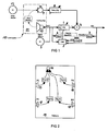
- FIG 1 is a schematic diagram of an adaptive finite impulse response (FIR) filter with an adaptation step size ⁇ [n].
- Said filter comprises a finite impulse response (FIR) filter core 1 which is controllable by a Least Mean Square (LMS) adaption unit 2.
- LMS unit 2 receives as an input signal a source signal x[n] from a signal source (e. g., a CD player, radio, etc.), an error signal e[n] from a subtraction unit 4, and an adaption step size ⁇ [n] from a step size calculation unit 5.
- a signal source e. g., a CD player, radio, etc.
- an error signal e[n] from a subtraction unit 4
- ⁇ [n] from a step size calculation unit 5.
- the step size calculation unit 5 may be supplied with a mean source signal Mean X[n], an estimated system distance Dist[n] supplied by the FIR filter core 1, and a mean error signal Mean E[n].
- the signals Mean X[n] and Mean E[n] are provided each by a averaging unit 6 or 7, respectively.
- the substraction unit 4 further receives via a delay unit 8 a signal from a microphone 9 which is part of a loud-speaker-room-microphone (LRM) system 10.
- Said LRM system further comprises a room 11 having a transfer function H Room (Z), in which the microphone 9 and a loudspeaker 12 supplied with source signal x[n] are arranged.
- the microphone 9 receives acoustic signals from the loudspeaker 12 filtered by the transfer function H Room (z) and noise signals from at least one noise source 13 outside (as shown) and/or inside (not shown) the room 11.
- both the source signal, x[n], and the resulting output signal of the adaptive filter - i.e., the error signal e[n], are recursively determined using a simple 1st order Infinite Impulse Response (IIR) low-pass filter.
- IIR Infinite Impulse Response
- the use of the DVC system is usually restricted solely to the lower spectral range, but even this range is generally not emitted from just one, but from a number of loudspeakers located in different positions within the listening room.
- the source signal played through the considered loudspeaker representing the reference signal by x x [ n ] , which is folded with the room impulse response between the source signal and the microphone, affects the composite signal recorded by the microphone.
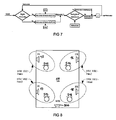
- FIG 2 is an example of a four-speaker/one-microphone arrangement.
- the arrangement comprises a microphone 14 and four loudspeakers 15,16,17,18 arranged in the front left (FL), front right (FR), rear left (RL), and the rear right (RR) of a room 19 which is in the present exemplary case the interior of a vehicle.
- a room transfer function H 1 (2), H 2 (2), H 3 (2), H 4 (2) respectively.
- This system functions quite well on average, but that it still appears to be inadequate in terms of a broader range of applications.
- the system of FIG 2 consisting of four different loudspeakers and a microphone is considered.
- the composition of the resulting composite reference signal, x[n] can be improved by considering in the calculation of the additive reference signal at least the different signal delay times and amplitudes resulting from the different distances of the loudspeakers from the microphone.
- the nearest loudspeaker in the present case loudspeaker 15
- the additional (acoustic) signal delays and attenuations in relation to the reference point are determined.
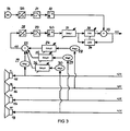
- FIG 3 illustrates a system using an improved composition of the composite reference signal.
- the system of FIG 3 comprises the microphone 14 (as in FIG 2 ) connected to an analog-to-digital (AD) converter 20 for converting an analog signal from the microphone 14 into a digital signal which is fed into a low pass (LP) filter 21 serving as an anti-aliasing filter for the subsequent sample rate conversion unit 22 which changes the sample rate by, e.g., 16.
- AD analog-to-digital
- LP low pass
- the composite reference signal x[n] which is the sum of individual source (reference) signals x 1 [n], x 2 [n], x 3 [n], x 4 [n] each supplied to the loudspeaker 15, 16, 17, 18 respectively, is provided by an adder unit 23 wherein the source signals x 2 [n], x 3 [n], and x 4 [n] each are supplied to the adder unit 23 via a delay unit 24 ('Delay 2'), 25 ('Delay 3'), and 26 ('Delay 4') respectively and an attenuation unit 28 (Mag2), 29 (Mag3), and 30 (Mag4).
- the source signal x 1 [n] is supplied to the adder unit 23 via an attenuation unit 27 only.
- An analog-to-digital (AD) converter 28 is connected to the adder unit 28 for converting the analog additive reference signal x[n] into a digital signal which is fed into low pass (LP) filter 29 serving as an anti-aliasing filter for a subsequent sample rate conversion unit 30.
- the output signal of sample rate conversion unit 30 is fed via a delay unit 31 into a finite impulse response (FIR) filter core 32 and a least mean square (LMS) filter control unit 34 for controlling the FIR filter core 32.
- FIR finite impulse response
- LMS least mean square
- the output of FIR filter core 32 is connected to one input of a subtraction unit 33 wherein a second input of subtraction 33 is connected to the output of sampling rate conversion unit 22.
- Subtraction unit 33 outputs the error signal e[n] which is fed back to the filter control unit 34 for a comparison with the delayed reference signal x[n].
- Error signal e[n] may also be supplied to other units as, for example, a predictive error filter as shown in FIG 6 .
- each component of the reference signal is considered as delay or amplification or attenuation factor in the composition of the reference signal.
- the basic delay inherent in the path from the reference loudspeaker 15 the microphone 14, which is referred to as 'Delayl' or ('bulk delay') can be considered within the undersampled signal processing range in order to increase the effective length of the adaptive filter. In doing so, an attempt is made to move the long delays into the undersampled range as much as possible to reduce memory consumption and to equalize only the differences in delay at the full sampling frequency using delay lines.
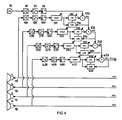
- FIG 4 is a schematic diagram of a DVC system to include all room transfer functions.
- the system of FIG 4 comprises a signal path (microphone path) established by the microphone 14, the AD converter 20, the low-pas filter 21, and the sampling rate conversion unit 22.
- a path (reference path 1) comprising an AD converter 128, a low-pass filter 129, a sampling rate conversion unit 130, a delay unit 131, a FIR filter core 132, a filter control unit 134, and a subtraction unit 133, wherein the AD converter 128 receives the reference signal x 1 [n] (instead of signal x[n] of FIG 3 ) and the subtraction unit 133 provides an error signal e 1 [n] from the processed microphone signal and the processed reference signal x 1 [n].
- the system of FIG 4 comprises three further reference paths (reference paths 2, 3, 4) established each by AD converters 228, 328, 428; low pass filters 229, 329, 429; sampling rate conversion units 230, 330, 430; delay units 231, 331, 431; FIR filter cores 232, 332, 432; filter control units 234, 334, 434; and subtraction units 233, 333, 433 wherein each AD converter 28 receives the respective reference signal x 2 [n], x 3 [n], x 4 [n] and the subtraction units 233, 333, 433, provide error signals e 2 [n], e 3 [n], and e 4 [n] from the error signals e 1 [n], e 2 [n], and e 3 [n] and the processed reference signals x 2 [n], x 3 [n], and x 4 [n] respectively.
- the reference paths 1, 2, 3, and 4 are identical at least in structure.
- the second adaptive filter in reference path 2) can adapt only if there are components in e 1 [n] that are correlated with x 2 [n]. Otherwise, the filter transfers the signal that is also not correlated with x 2 [n] as its output signal, and so forth.
- a signal is correspondingly output that is correlated with neither x 1 [n], x 2 [n], x 3 [n] nor x 4 [n] - i.e., all that remains is a signal mixture comprising the speech signal and background noise, represented in FIG 4 as 'Noise[n]'.
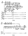
- FIG 5 illustrates such a mixture of the two systems shown in FIGs 3 and 4 .
- the system of FIG 5 has a microphone path and the reference paths 1, 2 as shown in the system of FIG 4 .
- path 2 i.e. AD converter 2278 is not supplied with reference signal x 2 [n] as in FIG 4 but is supplied with a mean reference signal similar to the one of FIG 3 .
- said mean reference signal is provided by an adder unit 123 receiving the processed reference signals x 2 [n], x 3 [n], x 4 [n].
- reference signal x 2 [n] is provided to the adder unit 123 via an attenuation unit 127 and reference signals x 3 [n], x 4 [n] via attenuation units 29, 30 and delay units 25, 26 respectively.
- the additive error signal Noise[n] is output by subtraction unit 233.
- One of the DVC alternative models known has, at least optionally, a high-pass filter arranged after the adaptive filter.
- the function of the high-pass filter is to smooth the noise spectrum - which is known to have very low frequencies in vehicles - to such an extent that the DVC system can respond not only to the predominant engine and movement noises but also to high-frequency wind noise, which has much weaker signal levels. Even though wind noise has considerably weaker levels than those of the low-frequency components, it is found in a spectral region in which human hearing is particularly sensitive, and therefore even a low noise signal level requires a control mechanism.
- a high-pass filter was used to smooth the noise spectrum as much as possible so that the system can respond practically equally well to both low-frequency noise and the high-frequency wind noise signals just described.
- the high-pass filter was set to a fixed value and then left unchanged. This setting is adequate for the majority of cases, as demonstrated in many tests, but there are certain noise situations in which the high-pass filter may act poorly - in other words, the filter does not appreciably smooth the spectrum of the noise signal, with the effect that there are different responses to noise signals with differing spectral distribution.
- the spectral smoothing filter may be set adaptively in response to the currently applicable noise situation, wherein linear predictive coding (LPC) analysis is utilized by feeding a predictor error filter (also known as a pre-whitening filter) with the iteratively calculated reflection coefficient.
- LPC linear predictive coding
- the system is also able to configure the equalizing filter according to the pertaining noise situation in such a way that the output signal of the predictor error filter is distributed across the spectrum as white noise as much as possible.
- FIG 6 illustrates the use of a whitening filter in place of a simple high-pass filter for spectral smoothing of a noise signal, wherein only just one reference path (reference path 1 of FIG 5 ) is used for explanation purposes in FIG 6 but can easily adapted for the other paths.
- high-pass filters 35 and 135 are included into the microphone path and the reference path (reference path 1) after the sample rate conversion units respectively.
- the error signal e[n] provided by the subtraction unit 133 is fed into a predictive error filter 36 which is controlled by a linear predictive coding (LPC) unit 37 receiving the error signal e[n], too.
- LPC linear predictive coding
- AEC acoustic echo cancellation
- the voice component in the microphone signal on which the LPC analysis was based is spectrally smoothed after the predictor error filter - i.e., it is whitened (thus giving rise to the term "pre-whitening filter").
- LPC linear predictive coding
- the analysis/synthesis method known as linear predictive coding (LPC) is an efficient and effective mean, for example, to achieve synthetic speech and speech signal communication.
- the efficiency of the method is due to the speed of the analysis algorithm and to the low bandwidth required for the encoded signals.
- the effectiveness is related to the intelligibility of the decoded vocal signal.
- LPC implements a type of vocoder which is an analysis/synthesis scheme where the spectrum of a source signal is weighted by the spectral components of the target signal that is being analyzed.
- the phase vocoder is, for example, a special kind of vocoder where amplitude and phase information of the analysis channels is retained and can be used as coefficients for an error filter.
- the source signals are either white noise or a pulse train, thus resembling voiced or unvoiced excitations of the vocal tract, respectively.
- the basic assumption behind LPC is the correlation between the n-th sample and the p previous samples of the target signal. Namely, the n-th signal sample is represented as a linear combination of the previous P samples, plus a residual representing the prediction error.
- the analysis problem is equivalent to the identification of the coefficients a of an all-pole filter.
- the filter 1/A(z) is called the all-pole formant filter because, if the proper order p is chosen, its magnitude frequency response follows the envelope of the signal spectrum, with its broad resonances called formants.
- the filter A(z) is called the inverse formant filter because it extracts from the voice signal a residual resembling the vocal tract excitation.
- A(z) is also called a whitening filter because it produces a residual having a flat spectrum.
- the pulse train and the white noise there are two kinds of residuals, both having a flat spectrum: the pulse train and the white noise, the first being the idealized vocal-fold excitation for voiced speech, the second being the idealized excitation for unvoiced speech.
- the residual is neither one of the two idealized excitations.
- the choice is either to use an encoded residual or to choose one of the two idealized excitations according to a voiced/unvoiced decision made by the analysis stage.
- a pitch detector can be added to the analysis stage, so that the re-synthesis can be driven by periodic replicas of a basic pulse, with the correct inter-pulse period.
- Several techniques are available for pitch detection, either using the residual or the target signal.
- the information extracted by the analysis stage are the prediction coefficients a 1 ,...,a p ; the residual e; pitch of the excitation residual; voiced/unvoiced information; and signal energy (RMS amplitude).
- These parameters, possibly modified, are used in the re-synthesis stage, for example, by means of the well-known Levinson-Durbin recursion, which provides the reflection coefficients of the lattice realization of the filter 1/A(z).
- An effective means of doing this is to compute the linear predictive coding (LPC) coefficients using LPC analysis, and to input the coefficients into a predictor filter with which the music signal is weighted.
- LPC linear predictive coding
- Known DVC systems always use a simple voice activity detection (VAD) function that makes use of the long-term steady state of the background noise signal and the short-term steady state of the human voice with the aid of two mean value calculation units.
- VAD voice activity detection
- This VAD variant is nonetheless extremely difficult to control, and for this reason a new VAD model that is easier to control and also even simpler to implement is preferred.
- FIG 7 shows the signal flow diagram for a new voice activity detection (VAD) model.
- VAD voice activity detection
- the new VAD model simply examines whether the current noise value (Noise[n]) is greater than the previous noise level (NoiseLevel[n]). If this is the case, the new noise level (NoiseLevel[n+1]) is calculated from the previous noise level in such a manner that this noise level increases by a permanently defined increment, regardless of how much the current noise signal value is greater than the previous noise level.
- the new noise level value is reduced by a fixed decrement.
- the increment is generally defined to be less than the decrement in order that there is no agitated response to brief energy spikes in the noise signal.
- the noise level is restricted to a low limit value using the low threshold value of the noise level, 'MinNoiseLevel'. The noise level is prevented from falling below a specific level in this way. Without a low threshold value of this kind, the system would at times respond much too slowly to a rising noise signal because the rising speed (which is governed by the increment) is slower than the falling speed.
- the DVC systems previously described were always operated with just one microphone. The noise situation was only recorded at the mounting point of the microphone. This information was then used to develop a global controlled variable for the entire vehicle. However, a number of aspects were not considered, which can lead to errors. For example, if the microphone is positioned where standing waves are located in the interior of the vehicle, the system can respond only inadequately or not at all to noise signals at exactly the same frequencies. Ideally, the microphones should always be positioned where the passenger's head currently is, because this noise situation at every position affects the passenger's auditory perception, which is intended to be enhanced using DVC and DEC systems.
- FIG 8 is an example of an arrangement of a multi-channel DVC/DEC system in a room 19.
- the simplest method of obtaining an individually adapted control system is to deploy the loudspeakers 15, 16, 17, 18 located nearest to associated microphones 515, 516, 517, 518 for control of the amplitude through the DVC system and control of the equalization through the DEC system. Only the spectral range of a subwoofer 500 would then need to be controlled globally. This is however readily acceptable as the range cannot generally be localized, and the human ear is in any case quite insensitive in this frequency range to variations in signal level.
- LPC linear predictive coding
- GAL gradient adaptive lattice
- the reflection coefficients deriving from the analysis are set in such a way that when included in a predictor filter (all-pole filter), whose transfer function more or less exactly matches the characteristics of the noise signal's power spectrum density (PSD), depending on the predictor order selected.
- the LPC analysis returns reflection coefficients whose values are based exclusively on the PSD development of the analyzed noise signal, but that do not provide any information on the signal's amplitude relationships. Furthermore, the amplitude of the predictor filter is much too high to be ever directly used.
- Equation 4 is a formula for calculating the scaling factor according to the L1 standard.
- an infinite number of values of the filter's impulse response is required in theory to calculate the scaling factor exactly according to the L1 standard, which is however impossible in practical terms.
- restriction was made to the assumption of a limited impulse response, which is then used to calculate the scaling factor ('scale') according to the L1 standard.
- the length of the impulse response is defined on the basis of both the error that is made when calculating the scaling factor and of the update time with which is wanted (or needed) to generate a scaling factor applicable to the next impulse response interval.
- the predictor filter's maximum value is 0 dB (i.e., it is scaled to 0 dB)
- This decision is mainly dependent on the current noise level that we have already determined using the DVC system. This implies that it is practical to couple the DEC and DVC systems together.
- the question is still posed as to how the equalizing filter can be controlled on the basis of the existing noise level or in what structure it can be applied.
- FIG 9 illustrates the structure of the equalizing filter.
- the equalizing (EQ) filter it is referred back to that of peaking filters.
- a gain control can be used to set how far the implemented EQ filter is to extend beyond the reference amplitude, which is also normally at 0 dB.
- This structure is chosen for the EQ filter - i.e., the gain from the DVC system indicates how much the maximum spectral share of the EQ filter scaled (by 'Scale') to 0 dB should be higher than the reference amplitude. In this way, only the spectral components that are particularly strongly concealed by background noise are amplified along with the DVC gain.
- the filter illustrated in FIG 9 comprises a source 40 connected to a subsequent adder unit 41 as well as a scaling unit 42.
- a equalizing (EQ) filter 43 and a subsequent gain adjusting unit 44 are connected downstream to the scaling unit 42.
- the output signal provided by the gain adjusting unit 44 is fed into the adder unit 41, whose output signal is (via units not shown) to a loudspeaker 45.
- FIG 10 is an example of a simple DVC/DEC system.
- the new gain value can be calculated together with the previously determined scaling factor to produce a further version of the DVC/DEC system.
- the filter of FIG 9 is applied to system of FIG 10 such that the filter is not connected directly to the source but through a gain adjusting unit 46 which is controlled by a DVC unit 47.
- the DVC unit 47 is supplied with signals from the loudspeaker 45 and a microphone 48 and further controls an LPC unit 49 and a gain calculation unit 50.
- the DVC unit 47 and the gain calculation unit 50 are further controlled by a volume control 51.
- the EQ filter 43 is controlled by the LPC unit 49 which further controls via a Dirac pulsed filter 52 and scaling calculation unit 53 the scaling unit 42, wherein gain adjusting unit 44 is controlled by gain calculation unit 50.
- FIG 11 is a another simple DVC/DEC system.
- the system of FIG 11 differs from the system of FIG 10 in that in the system of FIG 11 the scaling unit 42 is not connected between gain adjusting unit 46 and EQ filter 43 (as in FIG 10 ) but between the output of gain calculation unit 50 and the control input of gain adjusting unit 44.
- FIG 12 is an example for an complex DVC/DEC system according to the invention.
- the system of FIG 12 has a microphone path and a reference path.
- the microphone path is established by a microphone 614, an AD converter 620, a low-pas filter 621, and a sampling rate conversion unit 622, and an A-weighting high-pass filter 623.
- the reference path is established by an AD converter 628, a low-pass filter 629, a sampling rate conversion unit 630, an A-weighting high-pass filter 624, a delay unit 631, wherein the AD converter 628 receives a reference signal from an adder unit 615 connected to two delay units 616, 617.
- Said delay units 616, 617 are each supplied with a signal provided to two loudspeakers 6 via an amplifying unit 618, 619 respectively.
- the reference path further comprises an adaptive filter having a finite impulse response (FIR) filter core 641 which is controllable by a Least Mean Square (LMS) adaption unit 642.
- the LMS unit 642 receives as an input signal a signal from the delay unit 641, an error signal e[n] from a subtraction unit 6444, and an adaption step size ⁇ [n] from a step size calculation unit 645.
- the step size calculation unit 645 is supplied with a mean source signal Mean X[n] tapped from the (down-) sampling conversion unit 631 via an average unit 650, an estimated system distance Dist[n] supplied by the FIR filter core 641, and a mean error signal Mean E[n] tapped from the subtraction unit 644 via an average unit 651.
- the substraction unit 644 further receives via the microphone path a signal from the microphone 614 which is part of a loudspeaker-room-microphone (LRM) system (not shown in FIG 12 ).
- LRM loudspeaker-room-microphone
- Said LRM system further comprises a room having a transfer function H Room (Z), and the two loudspeakers 612, 613.
- the error signal e[n] is supplied via a scaling unit 659 to a prediction error filter core 660 serving as a whitening filter. Downstream the filter core 660 there is an averaging unit 661, a voice activity detector 662, a gain correction unit 663, a maximum gain unit 664, and a compare unit 665 evaluating whether gain below 1 or not. If so, the gain of an amplifying unit 666 is set to 1, and if not, the gain is left unchanged.
- the amplifying unit 666 is supplied with an electrical sound signal from a sound source (e. g.
- a prediction filter core 667 which is controlled by a linear predictive coding unit 658 supplied with the error signal e[n].
- a scaling unit 668 and an adder unit 669 which also receives the signal from the amplifying unit 666 input into the filter core 667.
- the output signal of adder unit 669 is processed by a sound signal processing unit 670 in a common way and supplied to loudspeakers 612 and 613.
- the gain settings from the compare unit 665 as well as mean volume settings 671 by the listener are used to set a gain control unit 672 for controlling the gain correction unit 665.
- the mean volume settings 671 are further used to control a gain control unit 673 for controlling a scaling unit 674.
- the scaling unit 674 which controls the scaling unit 668 further receives signals from a Dirac pulsed prediction filter 675 and the VAD 662.
- the Dirac pulsed prediction filter 675 controls the prediction error filter 660 by copying its filter coefficients into the prediction error filter 660.
- the reference signal should be tapped as much as possible at the end of the signal processing chain to prevent negative effects of the equalizing and dynamic modifications (limiters, compressors, etc.) on the performance of the adaptive filter.
- One way of improving the performance is to use a single, broadband output signal for which no addition is performed. This is also permissible provided all output signals are strongly correlated with each other, which is usually the case with audio signals.
- broadband output signals of this nature are rarely found in signal flow diagrams since the output signals are generally adapted to the bandwidths of the connected loudspeakers using crossover filters before they are output, and are consequently limited in bandwidth.
- the optimum solution is then that using the reference signal generation as illustrated in FIG 13 because it makes use of all correlations when generating the reference signal and dispenses with all signal addition operations.
- Yet another method likewise embodies an alternative method for reference signal generation.
- the reference signal is generated from one or more input signals.
- the output signal of the mixer which mixes all source signals together, represents a good input signal for said purpose.
- the signal amplitude is still a problem though in that it is likewise modified by the mixer.
- the maximum value of the sum of all loudness values (volumes) of the source signals is determined, and its difference to the fully driven signal is calculated - which is actually the equivalent of the scaling factor.
- FIG 13 illustrates a model for generating the reference signal and reference volume.
- a mono signal is generated from the stereo music input signals 'MusicLeft' and 'MusicRight' before being fed into a mixing matrix 60. This is not absolutely necessary, but it simplifies the mixing matrix 60.
- the problem associated with impure phase addition normally does not occur, or only to a minor degree, in this system as no signal processing has yet been performed using the two music signals, thereby rendering the risk of reference signal distortion minimal.
- a gain correction (scaling unit 62 in connection with Maximum volume search 61 and Difference-to-full-scale calculation unit 63) function may be integrated to modify the noise level value ('NoiseLevel' in FIG 15 ) weighted with the correction factor (Corr) deriving from the anti-gain chase function.
- the weighted level is referred to as the ratio.
- FIG 14 shows the characteristic of the gain correction function.
- FIG 15 illustrates the implementation of a gain correction function.
- the gain correction function is controlled by two parameters, namely noise threshold (NoiseTH) and NoiseSlope which is the slope of the righthand line of FIG 14 .
- NoiseTH is used to control how a measured increase in the background noise level results in a volume increase. Below NoiseTH the ratio is about 1:1 and above it is as NoiseSlope indicates below 1:1. A reason for this may be that, as an outcome of undersampling, lower frequency components being used basically only for the calculation of the gain factors increase more than higher frequency components do with an increase of the background noise.
- the system as to be adapted by introducing a gain correction function to address the issue outlined above.
- the gain correction function may be incorrect for lower frequencies but this incorrectness may be overcome by arranging the DVC gain units downstream a loudness processing unit.
- the DEC may be adapted to compensate for the incorrectness.
- the period is quite long until the genuine end noise level value is reached so that appropriate countermeasures can be taken.
- the waiting time is due to the low slew rate (C_INC) with which the system responds to increasing noise levels.
- C_INC low slew rate
- the threshold value, 'MinNoiseLevel' is used to prevent the noise level from falling below a specific level, which in effect is identical to the activation threshold of the system. However, care must be taken to avoid setting the threshold too high as otherwise the control function could be activated although the noise level is not high enough.
- MaxGain the maximum permissible control dynamics
- MinNoiseLevel the activation threshold
- t_MNTH the maximum gain
- Scale the noise scaling factor
- m_MNTH the slope of the anti-gain chase function
- FIG 17 illustrates an implementation of the MinNoiseTH (activation threshold) function.
- the use of an adaptation step ⁇ [n] size has shown itself to be very helpful in practice.
- the negative effects of strong, brief noise signals - for example, the human voice - were able to be reduced to a minimum using the appropriate step size, especially in the case of transmission of loud, bass source signals since these contribute little or nothing in the calculation of the noise level.
- the energy of the error signal MeanE[n](see FIG1 ) must be scaled according to the amplitude of the reference signal when tuning the adaptation step size (the reference signal should be driven as much as possible, as described earlier). The greater the effect of the reference signal in the calculation of the adaptation step size, the more the energy of the error signal must be scaled upwards. The converse applies equally.
- ⁇ Max [n] the maximum permissible adaptation step size
Landscapes
- Physics & Mathematics (AREA)
- Engineering & Computer Science (AREA)
- Acoustics & Sound (AREA)
- Signal Processing (AREA)
- Soundproofing, Sound Blocking, And Sound Damping (AREA)
- Circuit For Audible Band Transducer (AREA)
- Tone Control, Compression And Expansion, Limiting Amplitude (AREA)
- Fittings On The Vehicle Exterior For Carrying Loads, And Devices For Holding Or Mounting Articles (AREA)
- Details Of Audible-Bandwidth Transducers (AREA)
Claims (58)
- Anordnung zur Verbesserung eines Audiosignals zur Kompensation von Umgebungsgeräusch in einer Hörumgebung, die aufweist
Audiosignalmittel (12, 45) zur Erzeugung eines elektrischen Schallsignals erzeugen und zur Bildung einer Schallausgabe aus dem elektrisches Schallsignal;
Sensormittel (9, 48) zur Erzielung eines Gesamtschallsignals das kennzeichnend ist für einen Gesamtschallpegel in der Umgebung (11), wobei der Gesamtschallpegel sowohl die Schallausgabe des Audiosignalmittels wie auch das Umgebungsgeräusch (13) in der Umgebung aufweist;
Extrahierungsmittel (1, 2, 4, 5, 6, 7, 8, 47), die auf das Gesamtschallsignal und auf ein von dem elektrischen Schallsignal abgeleitetes Referenzsignal (Y[n]) ansprechen, um aus dem Gesamtschallsignal ein Umgebungsgeräusch- (Noise) Signal zu extrahieren das kennzeichnend ist für das Umgebungsgeräusch in der Umgebung; wobei das Extrahierungsmittel (1, 2, 4, 5, 6, 7, 8, 47) ein adaptives Filter (1) mit einer adaptiven Adaptionsschrittweite aufweist;
Steuerungsmittel (49, 50), die auf das extrahierte Umgebungsgeräuschsignal ansprechen um in Abhängigkeit von dem extrahierten Umgebungsgeräuschsignal ein Steuerungssignal zu erzeugen; und
Entzerrmittel (41, 42, 43, 44, 52, 53), die auf das Steuerungssignal ansprechen um die Schallausgabe des Audiosignalmittels (12, 45) abzugleichen um das Umgebungsgeräusch zu kompensieren; und gekennzeichnet durch
eine Schrittweitenberechnungseinheit (5) zur Steuerung der adaptiven Adaptionsschrittweite des adaptiven Filters,
wobei der Schrittweitenberechnungseinheit (5) ein gemitteltes Referenzsignal (Mean X[n]), das einen Mittelwert des Referenzsignal repräsentiert, ein geschätzter Systemabstand (Dist[n]), und ein mittleres Fehlersignal (Mean E[n]), das einen Mittelwert des Umgebungsgeräusches repräsentiert, zur Verfügung gestellt wird. - Anordnung zur Verbesserung eines Audiosignals nach Anspruch 1, wobei die Schrittweite gleich ist dem Produkt aus dem gemittelten Referenzsignal und dem geschätzten Systemabstand geteilt durch das gemittelte Fehlersignal.
- Anordnung zur Verbesserung eines Audiosignals nach Anspruch 1 oder 2,
wobei das adaptive Filter einen Filterkern und eine Least Mean Square (LMS) Adaptionseinheit zur Steuerung des Filterkerns aufweist; wobei die LMS Adaptionseinheit durch die Schrittweitenberechnungseinheit gesteuert wird. - Anordnung zur Verbesserung eines Audiosignals nach einem der Ansprüche 1 bis 3, die weiterhin Verzögerungsmittel zur Verzögerung von entweder dem Gesamtschallsignal oder dem elektrische Schallsignal aufweist, die dem Extrahierungsmittel zur Verfügung gestellt werden.
- Anordnung zur Verbesserung eines Audiosignals nach einem der Ansprüche 1 bis 4, wobei das Extrahierungsmittel einen Gesamtschallsignalpfad aufweist der ein Tiefpassfilter und eine Abtastratenumsetzungseinheit zur Verarbeitung des Gesamtschallsignals des Sensormittels aufweist.
- Anordnung zur Verbesserung eines Audiosignals nach einem der Ansprüche 1 bis 5, wobei das Extrahierungsmittel einen Referenzsignalpfad aufweist der ein Tiefpassfilter und eine Abtastratenumsetzungseinheit zur Verarbeitung des Referenzsignals aufweist.
- Anordnung zur Verbesserung eines Audiosignals nach einem der Ansprüche 1 bis 6, wobei das Audiosignalmittel zumindest zwei elektrische Schallsignale erzeugt und zumindest zwei Schallausgaben aus den elektrischen Schallsignalen bildet;
wobei die zumindest zwei elektrischen Schallsignale in einer Referenzsignalberechnungsanordnung verarbeitet werden, um ein einzelnes Referenzsignal zu bilden. - Anordnung zur Verbesserung eines Audiosignals nach Anspruch 7, wobei die Verarbeitung der elektrischen Schallsignale das Bedämpfen und/oder das Verzögern von jedem elektrischen Schallsignal und das Summieren der bedämpften und/oder der verzögerten elektrischen Schallsignale umfasst.
- Anordnung zur Verbesserung eines Audiosignals nach einem der Ansprüche 1 bis 8, wobei das Audiosignalmittel zumindest zwei elektrische Schallsignale erzeugt und zumindest zwei Schallausgaben aus den elektrischen Schallsignalen bildet;
wobei die zumindest zwei elektrischen Schallsignale jedes ein Referenzsignal ausformen, das dem Extrahierungsmittel zur Verfügung gestellt wird. - Anordnung zur Verbesserung eines Audiosignals nach Anspruch 9, wobei das Extrahierungsmittel für jedes Referenzsignal einen Referenzsignalpfad aufweist der ein Tiefpassfilter und eine Abtastratenumsetzungseinheit zur Verarbeitung des Referenzsignals aufweist.
- Anordnung zur Verbesserung eines Audiosignals nach Anspruch 10, wobei das Extrahierungsmittel für jeden Referenzsignalpfad ein adaptives Filter aufweist und die Ausgangssignale von jedem adaptiven Filter dem nachfolgenden adaptiven Filter als Gesamtschallsignal zur Verfügung gestellt werden.
- Anordnung zur Verbesserung eines Audiosignals nach einem der Ansprüche 1 bis 6, wobei das Audiosignalmittel zumindest drei elektrische Schallsignale erzeugt und zumindest drei Schallausgaben aus den elektrischen Schallsignalen bildet;
wobei eines der zumindest drei elektrischen Schallsignale ein Referenzsignal ausformt das dem Extrahierungsmittel zur Verfügung gestellt wird und die anderen der zumindest drei elektrischen Schallsignale verarbeitet werden, um ein weiteres Referenzsignal auszuformen. - Anordnung zur Verbesserung eines Audiosignals nach Anspruch 12, wobei die anderen elektrischen Schallsignale in einer Referenzsignalberechnungsanordnung verarbeitet werden um ein einzelnes Referenzsignal zu bilden.
- Anordnung zur Verbesserung eines Audiosignals nach Anspruch 13, wobei
die Verarbeitung der elektrischen Schallsignale das Bedämpfen und/oder das Verzögern von jedem elektrischen Schallsignal und das Summieren der bedämpften und/oder der verzögerten elektrischen Schallsignale umfasst. - Anordnung zur Verbesserung eines Audiosignals nach einem der Ansprüche 1 bis 14, die weiterhin ein prädiktives Fehlerfilter aufweist, das dem Extrahierungsmittel nachgeschaltet verbunden ist.
- Anordnung zur Verbesserung eines Audiosignals nach Anspruch 15, das weiterhin eine Linear Predictive Coding (LPC) Einheit zur Steuerung des prädiktiven Fehlerfilters aufweist.
- Anordnung zur Verbesserung eines Audiosignals nach Anspruch 1 bis 16, wobei jedes Referenzsignal durch das Verzögerungsmittel verzögert wird.
- Anordnung zur Verbesserung eines Audiosignals nach Anspruch 17, die weiterhin einen Stimmenaktivitätsdetektor (VAD) aufweist.
- Anordnung zur Verbesserung eines Audiosignals nach Anspruch 18, wobei das VAD Modell prüft ob der aktuelle Geräuschwert größer ist als der vorherige Geräuschpegel und, wenn dies der Fall ist, ein neuer Geräuschpegel aus dem vorherigen Geräuschpegel errechnet wird auf solch eine Weise, dass sich dieser Geräuschpegel um ein fest definiertes Inkrement erhöht, ohne Rücksicht darauf um wie viel der aktuelle Geräuschsignalwert größer ist als der vorherige Geräuschpegel.
- Anordnung zur Verbesserung eines Audiosignals nach einem der Ansprüche 1 bis 19, die weiterhin zusätzliche Sensormittel aufweist, wobei die gesamte Anzahl an Sensormitteln gleich ist der Anzahl der Schallausgaben, die aus den entsprechenden elektrischen Schallsignalen gebildet werden; wobei jedes der Sensormittel Referenzsignale zur Verfügung stellt.
- Anordnung zur Verbesserung eines Audiosignals nach Anspruch 20, wobei die Schallausgaben durch Lautsprecher ausgebildet werden und jedes Sensormittel nahe an dem entsprechenden Lautsprecher angeordnet ist.
- Anordnung zur Verbesserung eines Audiosignals nach einem der Ansprüche 1 bis 21, die weiterhin ein nachgeschaltet zu dem Entzerrmittel verbundenes Verstärkungsmittel zur Verstärkung des Ausgangssignals des Entzerrmittels aufweist.
- Anordnung zur Verbesserung eines Audiosignals nach Anspruch 22, wobei das Verstärkungsmittel durch ein Verstärkungsregelungsmittel gesteuert wird.
- Anordnung zur Verbesserung eines Audiosignals nach einem der Ansprüche 1 bis 23, die weiterhin ein Skalierungsmittel zum Skalieren des dem Entzerrmittel zur Verfügung gestellten elektrischen Schallsignals aufweist.
- Anordnung zur Verbesserung eines Audiosignals nach einem der Ansprüche 1 bis 23, die weiterhin ein Skalierungsmittel aufweist, das zwischen dem Verstärkungsregelungsmittel und dem Verstärkungsmittel verbunden ist.
- Anordnung zur Verbesserung eines Audiosignals nach Anspruch 24 oder 25, wobei das Skalierungsmittel durch ein Skalierungssteuerungsmittel gesteuert wird.
- Anordnung zur Verbesserung eines Audiosignals nach Anspruch 26, wobei das Skalierungssteuerungsmittel ein Dirac Filter und eine Skalierungsberechnungseinheit aufweist.
- Anordnung zur Verbesserung eines Audiosignals nach einem der Ansprüche 22 bis 27, wobei das Verstärkungsregelungsmittel einen minimalen Geräuschschwellenwert aufweist um zu verhindern, dass der Geräuschpegel unter einen bestimmten Pegel abfällt.
- Anordnung zur Verbesserung eines Audiosignals nach Anspruch 28, wobei der minimale Geräuschschwellenwert von einer Lautstärkeeinstellung abhängt.
- Verfahren zur Verbesserung des von einem Audiosystem in einer Hörumgebung erzeugten Schallsignals durch Kompensieren von Umgebungsgeräusch in einer Hörumgebung, das die Schritte aufweist
Erzeugen eines elektrischen Schallsignals und Bilden einer Schallausgabe (12, 45) aus dem elektrischen Schallsignal;
Erzielen eines Gesamtschallsignals (9, 48) das kennzeichnend ist für einen Gesamtschallpegel in der Umgebung (11), wobei der Gesamtschallpegel sowohl die Schallausgabe des Audiosignalmittels als auch das Umgebungsgeräusch in der Umgebung aufweist,
Extrahieren (1, 2, 4, 5, 6, 7, 8, 47) eines Umgebungsgeräuschsignals (Noise) das kennzeichnend ist für das Umgebungsgeräusch in der Umgebung aus dem Gesamtschallsignal und aus einem Referenzsignal (X[n]), das abgeleitet ist von dem elektrischen Schallsignal; wobei der Extrahierungsschritt eine adaptive Filterung (1) mit einer adaptiven Adaptionsschrittweite (µ[n]) aufweist,
Bilden (48, 50) eines von dem extrahierten Umgebungsgeräuschsignal (Noise) abhängigen Steuerungssignals als Reaktion auf das Umgebungsgeräuschsignal;
Abgleichen (41, 42, 43, 44) der Schallausgabe des Audiosignalmittels, um als Reaktion auf das Steuerungssignal den Umgebungsgeräuschpegel zu kompensieren; und
einen Schritt zur Schrittweitenberechnung (5) zur Steuerung der adaptiven Adaptionsschrittweite (µ[n]) der adaptiven Filterung,
wobei der Schritt zur Schrittweitenberechnung ein gemitteltes Referenzsignal (Mean X[n]), das einen Mittelwert des Referenzsignals darstellt, einen geschätzten Systemabstand (Dist[n]), und ein gemitteltes Fehlersignal (Mean E[n]), das einen Mittelwert des Umgebungsgeräusches darstellt, verarbeitet. - Verfahren nach Anspruch 30, wobei die Schrittweite gleich ist dem Produkt aus dem gemittelten Referenzsignal und aus dem geschätzten Systemabstand geteilt durch das gemittelte Fehlersignal.
- Verfahren nach einem der Ansprüche 30 bis 31, wobei das adaptive Filter eine durch einen Least Mean Square (LMS) Adaptionsschritt gesteuerte Filterung aufweist; wobei der LMS Adaptionsschritt durch einen Schrittweitenberechnungsschritt gesteuert wird.
- Verfahren nach einem der Ansprüche 31 bis 32, das weiterhin einen Verzögerungsschritt zum Verzögern entweder des Gesamtschallsignals oder des elektrischen Schallsignals aufweist, die dem Extrahierungsschritt zur Verfügung gestellt werden.
- Verfahren nach einem der Ansprüche 30 bis 33, wobei der Extrahierungsschritt zur Verarbeitung des Gesamtschallsignals eine Tiefpassfilterung und eine Abtastratenumsetzung aufweist.
- Verfahren nach einem der Ansprüche 30 bis 34, wobei der Extrahierungsschritt zur Verarbeitung des Referenzsignals eine Tiefpassfilterung und eine Abtastratenumsetzung aufweist.
- Verfahren nach einem der Ansprüche 30 bis 35, wobei zumindest zwei elektrische Schallsignale erzeugt werden und zumindest zwei Schallausgaben aus den elektrischen Schallsignalen gebildet werden; wobei die zumindest zwei elektrischen Schallsignale verarbeitet werden um ein einzelnes Referenzsignal zu bilden.
- Verfahren nach Anspruch 36, wobei die Verarbeitung der elektrischen Schallsignale das Bedämpfen und/oder das Verzögern von jedem elektrischen Schallsignal und das Summieren der bedämpften und/oder der verzögerten elektrischen Schallsignale umfasst.
- Verfahren nach einem der Ansprüche 30 bis 35, wobei das Audiosignalmittel zumindest zwei elektrische Schallsignale erzeugt und zumindest zwei Schallausgaben aus den elektrischen Schallsignalen bildet; wobei die zumindest zwei elektrischen Schallsignale jedes ein dem Extrahierungsmittel zur Verfügung gestelltes Referenzsignal ausformen.
- Verfahren nach Anspruch 38, wobei der Extrahierungsschritt für jedes Referenzsignal eine Tiefpassfilterung und eine Abtastratenumsetzung aufweist, um die Referenzsignale zu verarbeiten.
- Verfahren nach Anspruch 39, wobei der Extrahierungsschritt für jedes Referenzsignal eine adaptive Filterung und das Bereitstellen der Ausgangssignale von jedem adaptiven Filter als Gesamtschallsignal an das nachfolgende adaptive Filter aufweist.
- Verfahren nach einem der Ansprüche 30 bis 35, wobei zumindest drei elektrische Schallsignale erzeugt werden und zumindest drei Schallausgaben aus den elektrischen Schallsignalen gebildet werden; wobei eines der zumindest drei elektrischen Schallsignale ein Referenzsignal ausformt und die anderen der zumindest drei elektrischen Schallsignale ein weiteres Referenzsignal ausformen.
- Verfahren nach Anspruch 41, wobei die anderen elektrischen Schallsignale in einer Referenzsignalberechnungsanordnung verarbeitet werden, um ein einzelnes Referenzsignal zu bilden.
- Verfahren nach Anspruch 42, wobei die Verarbeitung der elektrischen Schallsignale das Bedämpfen und/oder das Verzögern jedes elektrischen Schallsignals und das Summieren der bedämpften und/oder der verzögerten elektrischen Schallsignale umfasst.
- Verfahren nach einem der Ansprüche 30 bis 43, das weiterhin eine prädiktive Fehlerfilterung aufweist.
- Verfahren nach Anspruch 44, das weiterhin Linear Predictive Coding (LPC) zur Steuerung der prädiktiven Fehlerfilterung aufweist.
- Verfahren nach Anspruch 30 bis 45, wobei jedes Referenzsignal verzögert wird.
- Verfahren nach Anspruch 30 bis 46, das weiterhin eine Stimmaktivitätserkennung (VAD) aufweist.
- Verfahren nach Anspruch 47, das den Schritt der Bestimmung aufweist ob der aktuelle Geräuschwert größer ist als der vorherige Geräuschpegel und wenn dies der Fall ist ein neuer Geräuschpegel aus dem vorherigen Geräuschpegel berechnet wird auf solch eine Weise dass sich dieser Geräuschpegel um ein fest definiertes Inkrement erhöht, ohne Rücksicht darauf um wie viel der aktuelle Geräuschsignalwert größer ist als der vorherige Geräuschpegel.
- Verfahren nach einem der Ansprüche 30 bis 48, das weiterhin das Bilden einer Vielzahl von Gesamtschallsignalen aufweist, wobei die gesamte Anzahl der Gesamtschallsignale gleich ist der Anzahl von Schallausgaben, die aus den entsprechenden elektrischen Schallsignalen gebildet werden; wobei jedes der Gesamtschallsignale Referenzsignale ausformt.
- Verfahren nach Anspruch 49, wobei jedes der Gesamtschallsignale Referenzsignale ausformt.
- Verfahren nach einem der Ansprüche 30 bis 50, das weiterhin einen Verstärkungsschritt zur Verstärkung des durch den Entzerrungsschritt gebildeten Signals aufweist.
- Verfahren nach Anspruch 51, wobei der Verstärkungsschritt durch einen Verstärkungsregelungsschritt gesteuert wird.
- Verfahren nach einem der Ansprüche 30 bis 52, das weiterhin einen Skalierungsschritt zur Skalierung des elektrischen Schallsignals aufweist, das dem Entzerrungsschritt zur Verfügung gestellt wird.
- Verfahren nach einem der Ansprüche 30 bis 53, das weiterhin einen Skalierungsschritt zwischen dem Verstärkungsregelungsschritt und dem Verstärkungsschritt aufweist.
- Verfahren nach Anspruch 53 oder 54, wobei der Skalierungsschritt durch einen Skalierungssteuerungsschritt gesteuert wird.
- Verfahren nach Anspruch 55, wobei der Skalierungssteuerungsschritt eine Dirac Filterung und eine Skalierungsberechnung aufweist.
- Verfahren nach einem der Ansprüche 51 bis 56, wobei der Verstärkungsregelungsschritt einen minimalen Geräuschschwellenwert aufweist um zu verhindern, dass der Geräuschpegel unter einen bestimmten Pegel abfällt.
- Verfahren nach Anspruch 57, wobei der minimale Geräuschschwellenwert von einer Lautstärkeeinstellung abhängig ist.
Priority Applications (5)
| Application Number | Priority Date | Filing Date | Title |
|---|---|---|---|
| EP05009835A EP1720249B1 (de) | 2005-05-04 | 2005-05-04 | System und Verfahren zur Intensivierung von Audiosignalen |
| DE602005015426T DE602005015426D1 (de) | 2005-05-04 | 2005-05-04 | System und Verfahren zur Intensivierung von Audiosignalen |
| JP2006053925A JP4755506B2 (ja) | 2005-05-04 | 2006-02-28 | オーディオ強化システムおよび方法 |
| US11/410,538 US8116481B2 (en) | 2005-05-04 | 2006-04-25 | Audio enhancement system |
| US13/372,097 US9014386B2 (en) | 2005-05-04 | 2012-02-13 | Audio enhancement system |
Applications Claiming Priority (1)
| Application Number | Priority Date | Filing Date | Title |
|---|---|---|---|
| EP05009835A EP1720249B1 (de) | 2005-05-04 | 2005-05-04 | System und Verfahren zur Intensivierung von Audiosignalen |
Publications (2)
| Publication Number | Publication Date |
|---|---|
| EP1720249A1 EP1720249A1 (de) | 2006-11-08 |
| EP1720249B1 true EP1720249B1 (de) | 2009-07-15 |
Family
ID=34982484
Family Applications (1)
| Application Number | Title | Priority Date | Filing Date |
|---|---|---|---|
| EP05009835A Expired - Lifetime EP1720249B1 (de) | 2005-05-04 | 2005-05-04 | System und Verfahren zur Intensivierung von Audiosignalen |
Country Status (4)
| Country | Link |
|---|---|
| US (2) | US8116481B2 (de) |
| EP (1) | EP1720249B1 (de) |
| JP (1) | JP4755506B2 (de) |
| DE (1) | DE602005015426D1 (de) |
Families Citing this family (56)
| Publication number | Priority date | Publication date | Assignee | Title |
|---|---|---|---|---|
| US7545849B1 (en) | 2003-03-28 | 2009-06-09 | Google Inc. | Signal spectrum spreading and combining system and method |
| US8374218B2 (en) | 2000-12-05 | 2013-02-12 | Google Inc. | Combining signals with a shuffled-hadamard function |
| US8385470B2 (en) | 2000-12-05 | 2013-02-26 | Google Inc. | Coding a signal with a shuffled-Hadamard function |
| US7453921B1 (en) * | 2001-12-11 | 2008-11-18 | Google Inc. | LPC filter for removing periodic and quasi-periodic interference from spread spectrum signals |
| US7352833B2 (en) | 2002-11-18 | 2008-04-01 | Google Inc. | Method and system for temporal autocorrelation filtering |
| US8964997B2 (en) | 2005-05-18 | 2015-02-24 | Bose Corporation | Adapted audio masking |
| EP1879181B1 (de) * | 2006-07-11 | 2014-05-21 | Nuance Communications, Inc. | Verfahren zur Kompensation von Audiosignalkomponenten in einem Fahrzeugkommunikationssystem und Vorrichtung dafür |
| WO2008081403A1 (en) * | 2006-12-29 | 2008-07-10 | Grundig Elektronik Anonim Sirketi | A method for reducing noise |
| US8953776B2 (en) * | 2007-08-27 | 2015-02-10 | Nec Corporation | Particular signal cancel method, particular signal cancel device, adaptive filter coefficient update method, adaptive filter coefficient update device, and computer program |
| EP2192694B1 (de) * | 2007-09-20 | 2015-04-29 | NEC Corporation | Systemidentifikationsvorrichtung und systemidentifikationsverfahren |
| EP2045620B1 (de) | 2007-09-26 | 2015-08-12 | Harman Becker Automotive Systems GmbH | Messung der akustischen Laufzeit |
| JP5003419B2 (ja) * | 2007-11-09 | 2012-08-15 | ヤマハ株式会社 | 音処理装置およびプログラム |
| WO2009104252A1 (ja) * | 2008-02-20 | 2009-08-27 | 富士通株式会社 | 音処理装置、音処理方法及び音処理プログラム |
| DE102008026232B4 (de) | 2008-05-29 | 2023-11-23 | Volkswagen Ag | Verfahren und Vorrichtung zur Steuerung eines Batterie-Lüfters in einem Kraftfahrzeug |
| JP5241921B2 (ja) * | 2008-07-29 | 2013-07-17 | ドルビー ラボラトリーズ ライセンシング コーポレイション | 電子音響チャンネルの適応制御とイコライゼーションの方法 |
| US8218783B2 (en) | 2008-12-23 | 2012-07-10 | Bose Corporation | Masking based gain control |
| EP2374211B1 (de) | 2008-12-24 | 2012-04-04 | Dolby Laboratories Licensing Corporation | Audiosignallautheitbestimmung und modifikation im frequenzbereich |
| US8229125B2 (en) | 2009-02-06 | 2012-07-24 | Bose Corporation | Adjusting dynamic range of an audio system |
| JP5355690B2 (ja) * | 2009-06-01 | 2013-11-27 | 三菱電機株式会社 | 信号処理装置 |
| US9299362B2 (en) * | 2009-06-29 | 2016-03-29 | Mitsubishi Electric Corporation | Audio signal processing device |
| US8634569B2 (en) * | 2010-01-08 | 2014-01-21 | Conexant Systems, Inc. | Systems and methods for echo cancellation and echo suppression |
| WO2011121782A1 (ja) * | 2010-03-31 | 2011-10-06 | 富士通株式会社 | 帯域拡張装置および帯域拡張方法 |
| KR20130038857A (ko) * | 2010-04-09 | 2013-04-18 | 디티에스, 인코포레이티드 | 오디오 재생을 위한 적응적 주변 소음 보상 |
| JP2012014106A (ja) * | 2010-07-05 | 2012-01-19 | Alpine Electronics Inc | 騒音補正装置 |
| US8868432B2 (en) * | 2010-10-15 | 2014-10-21 | Motorola Mobility Llc | Audio signal bandwidth extension in CELP-based speech coder |
| US8744091B2 (en) * | 2010-11-12 | 2014-06-03 | Apple Inc. | Intelligibility control using ambient noise detection |
| DE102011012573B4 (de) * | 2011-02-26 | 2021-09-16 | Paragon Ag | Sprachbedienvorrichtung für Kraftfahrzeuge und Verfahren zur Auswahl eines Mikrofons für den Betrieb einer Sprachbedienvorrichtung |
| JP5032682B1 (ja) | 2011-03-31 | 2012-09-26 | 株式会社東芝 | 特性補正装置および特性補正方法 |
| CN103620676B (zh) | 2011-04-21 | 2016-03-09 | 三星电子株式会社 | 对线性预测编码系数进行量化的方法、声音编码方法、对线性预测编码系数进行反量化的方法、声音解码方法以及记录介质 |
| CN103620675B (zh) | 2011-04-21 | 2015-12-23 | 三星电子株式会社 | 对线性预测编码系数进行量化的设备、声音编码设备、对线性预测编码系数进行反量化的设备、声音解码设备及其电子装置 |
| US9060237B2 (en) * | 2011-06-29 | 2015-06-16 | Harman International Industries, Incorporated | Musical measurement stimuli |
| KR101620248B1 (ko) | 2011-11-04 | 2016-05-12 | 인텔 코포레이션 | 협력 멀티포인트(comp) 시스템들에서의 다운링크(dl) 전송들을 위한 타이밍 동기화 |
| TWI449438B (zh) * | 2012-04-09 | 2014-08-11 | Quanta Comp Inc | 具有迴音消除機制之通訊系統及方法 |
| US8749312B2 (en) * | 2012-04-18 | 2014-06-10 | Qualcomm Incorporated | Optimizing cascade gain stages in a communication system |
| US8831935B2 (en) * | 2012-06-20 | 2014-09-09 | Broadcom Corporation | Noise feedback coding for delta modulation and other codecs |
| EP2864983B1 (de) * | 2012-06-20 | 2018-02-21 | Widex A/S | Verfahren für schallverarbeitung in einem hörgerät und hörgerät |
| US10414337B2 (en) | 2013-11-19 | 2019-09-17 | Harman International Industries, Inc. | Apparatus for providing environmental noise compensation for a synthesized vehicle sound |
| US9615185B2 (en) * | 2014-03-25 | 2017-04-04 | Bose Corporation | Dynamic sound adjustment |
| GB2532041B (en) * | 2014-11-06 | 2019-05-29 | Imagination Tech Ltd | Comfort noise generation |
| EP3156998B1 (de) * | 2015-10-16 | 2024-04-10 | Harman Becker Automotive Systems GmbH | Fahrbahn- und motorgeräuschsteuerung |
| EP3157001B1 (de) * | 2015-10-16 | 2023-05-10 | Harman Becker Automotive Systems GmbH | Motordrehzahl- und fahrbahn-geräuschkontrolle |
| US10026405B2 (en) * | 2016-05-03 | 2018-07-17 | SESTEK Ses velletisim Bilgisayar Tekn. San. Ve Tic A.S. | Method for speaker diarization |
| DE102016220365B4 (de) * | 2016-10-18 | 2022-02-17 | Audi Ag | Verfahren zum Betreiben einer Audioausgabevorrichtung, Audioausgabevorrichtung für ein Kraftfahrzeug und Kraftfahrzeug |
| CN107346658B (zh) * | 2017-07-14 | 2020-07-28 | 深圳永顺智信息科技有限公司 | 混响抑制方法及装置 |
| US10140089B1 (en) * | 2017-08-09 | 2018-11-27 | 2236008 Ontario Inc. | Synthetic speech for in vehicle communication |
| SE541331C2 (en) * | 2017-11-30 | 2019-07-09 | Creo Dynamics Ab | Active noise control method and system |
| SE1850077A1 (en) | 2018-01-24 | 2019-07-25 | Creo Dynamics Ab | Active noise control method and system using variable actuator and sensor participation |
| US11295718B2 (en) | 2018-11-02 | 2022-04-05 | Bose Corporation | Ambient volume control in open audio device |
| CN111147976B (zh) * | 2018-11-05 | 2024-08-06 | 上海中兴软件有限责任公司 | 调节音响音量平衡度的方法及装置、终端、存储介质 |
| DE102019102941A1 (de) * | 2019-02-06 | 2020-08-06 | Bayerische Motoren Werke Aktiengesellschaft | Verfahren, Vorrichtung und Computerprogramm zum Betreiben eines Audiosystems in einem Fahrzeug |
| US11095981B2 (en) * | 2019-06-06 | 2021-08-17 | Mitek Corp., Inc. | Root mean square adaptive filtering for ambient noise compensation systems |
| US12273692B2 (en) * | 2020-07-09 | 2025-04-08 | Toa Corporation | Public address device, howling suppression device, and howling suppression method |
| CN112233644B (zh) * | 2020-11-04 | 2024-05-31 | 华北电力大学 | 一种基于四元数自适应滤波器的滤波-x最小均方有源噪声控制方法 |
| GB2614064A (en) * | 2021-12-21 | 2023-06-28 | Nokia Technologies Oy | Apparatus, methods and computer programs for reducing echo |
| JP7709808B2 (ja) * | 2022-02-14 | 2025-07-17 | パナソニックオートモーティブシステムズ株式会社 | 音響処理装置、及び、音響処理方法 |
| CN116528101A (zh) * | 2023-04-17 | 2023-08-01 | 中国人民解放军海军潜艇学院 | 一种强环境噪声下船用耳罩语音增强方法 |
Family Cites Families (136)
| Publication number | Priority date | Publication date | Assignee | Title |
|---|---|---|---|---|
| US3714622A (en) | 1969-12-12 | 1973-01-30 | Us Navy | Adaptive agc system |
| US3934084A (en) | 1974-03-27 | 1976-01-20 | Television Research Limited | Variable gain amplifier controlled by ambient noise level |
| US3934085A (en) | 1973-03-28 | 1976-01-20 | Television Research Limited | Audio amplifier systems |
| US4025723A (en) | 1975-07-07 | 1977-05-24 | Hearing Health Group, Inc. | Real time amplitude control of electrical waves |
| FR2400279A1 (fr) | 1977-08-09 | 1979-03-09 | Simeau Bernard | Dispositifs d'analyse et de traitement de signaux |
| GB2013051A (en) | 1978-01-20 | 1979-08-01 | Secr Defence | Gain control in telecommunications systems |
| GB2029141A (en) | 1978-08-26 | 1980-03-12 | Viva Co | Gain control arrangements |
| CH644974A5 (de) | 1979-02-09 | 1984-08-31 | Blaupunkt Werke Gmbh | Schaltungsanordnung zum selbsttaetigen anpassen der lautstaerke mindestens eines lautsprechers an einen am lautsprecherort herrschenden stoergeraeuschpegel fuer rundfunkempfaenger. |
| DE3068929D1 (en) | 1979-03-05 | 1984-09-20 | Auguste Begarie | Dry vacuum cleaning machine for floors |
| US4297527A (en) | 1979-05-01 | 1981-10-27 | E-Systems, Inc. | Input gain adjusting apparatus and method |
| US4306115A (en) | 1980-03-19 | 1981-12-15 | Humphrey Francis S | Automatic volume control system |
| JPS56147525A (en) | 1980-04-18 | 1981-11-16 | Hitachi Ltd | Reception playback system |
| US4409435A (en) | 1980-10-03 | 1983-10-11 | Gen Engineering Co., Ltd. | Hearing aid suitable for use under noisy circumstance |
| JPS57136811A (en) | 1981-02-18 | 1982-08-24 | Nissan Motor Co Ltd | Automatic controller of sound volume |
| US4476571A (en) | 1981-06-15 | 1984-10-09 | Pioneer Electronic Corporation | Automatic sound volume control device |
| US4406923A (en) | 1981-10-28 | 1983-09-27 | Cbs Inc. | Automatic loudness controller |
| DE3374514D1 (en) | 1982-01-27 | 1987-12-17 | Racal Acoustics Ltd | Improvements in and relating to communications systems |
| US4438526A (en) | 1982-04-26 | 1984-03-20 | Conwed Corporation | Automatic volume and frequency controlled sound masking system |
| DE3220758A1 (de) | 1982-06-02 | 1983-12-08 | Hans-Christian 2872 Hude Persson | Verfahren zur selbsttaetigen anpassung der lautstaerke und der dynamik elektroakustischer signale an den am hoerort auftretenden stoerschallpegel |
| US4461025A (en) | 1982-06-22 | 1984-07-17 | Audiological Engineering Corporation | Automatic background noise suppressor |
| US5034984A (en) | 1983-02-14 | 1991-07-23 | Bose Corporation | Speed-controlled amplifying |
| DE3320751A1 (de) | 1983-06-09 | 1984-12-13 | Blaupunkt-Werke Gmbh, 3200 Hildesheim | Schaltungsanordnung zum selbsttaetigen anpassen der lautstaerke eines lautsprechers an einen am lautsprecherort herrschenden stoergeraeuschpegel |
| DE3322055A1 (de) | 1983-06-18 | 1984-12-20 | Blaupunkt-Werke Gmbh, 3200 Hildesheim | Schaltungsanordnung zum selbsttaetigen anpassen der lautstaerke eines lautsprechers an einen am lautsprecherort herrschenden stoergeraeuschpegel |
| US4590593A (en) | 1983-06-30 | 1986-05-20 | Nl Industries, Inc. | Electronic noise filtering system |
| DE3426068A1 (de) | 1983-09-22 | 1985-04-11 | Blaupunkt-Werke Gmbh, 3200 Hildesheim | Verfahren zum anpassen der lautstaerke eines lautsprechers an einen am lautsprecherort herrschenden stoergeraeuschpegel |
| JPS6072651A (ja) | 1983-09-30 | 1985-04-24 | Nippon Mining Co Ltd | 銅の連続鋳造装置 |
| JPH0669742B2 (ja) | 1983-10-13 | 1994-09-07 | 住友化学工業株式会社 | 加工性にすぐれた制振材料 |
| DE3338413A1 (de) | 1983-10-22 | 1985-05-02 | Blaupunkt-Werke Gmbh, 3200 Hildesheim | Schaltungsanordnung zum selbsttaetigen anpassen der lautstaerke eines lautsprechers an einen am lautsprecherort herrschenden stoergeraeuschpegel |
| US4553258A (en) | 1983-12-30 | 1985-11-12 | International Business Machines Corporation | Segmentation algorithm for signature vertification |
| US4641344A (en) | 1984-01-06 | 1987-02-03 | Nissan Motor Company, Limited | Audio equipment |
| US4649505A (en) | 1984-07-02 | 1987-03-10 | General Electric Company | Two-input crosstalk-resistant adaptive noise canceller |
| US4598417A (en) | 1984-08-15 | 1986-07-01 | Research Corporation | Electronic stethoscope |
| JPH0447705Y2 (de) | 1984-09-03 | 1992-11-11 | ||
| NL8403200A (nl) | 1984-10-22 | 1986-05-16 | Philips Nv | Lawaaiafhankelijke- en spraakonafhankelijke volumeregeling. |
| JPS61108212U (de) | 1984-12-18 | 1986-07-09 | ||
| US4636586A (en) | 1985-09-20 | 1987-01-13 | Rca Corporation | Speakerphone with adaptive cancellation of room echoes |
| JPH0720310B2 (ja) | 1985-10-23 | 1995-03-06 | 松下電器産業株式会社 | 音質調整装置 |
| CA1293693C (en) | 1985-10-30 | 1991-12-31 | Tetsu Taguchi | Noise canceling apparatus |
| JPS6292607U (de) | 1985-12-02 | 1987-06-13 | ||
| JPS62135020A (ja) | 1985-12-06 | 1987-06-18 | Nec Corp | 雑音消去装置 |
| US4696030A (en) | 1985-12-16 | 1987-09-22 | Elscint Ltd. | Patient operator intercom arrangements for magnetic resonance imaging systems |
| US4718099A (en) | 1986-01-29 | 1988-01-05 | Telex Communications, Inc. | Automatic gain control for hearing aid |
| US4731850A (en) | 1986-06-26 | 1988-03-15 | Audimax, Inc. | Programmable digital hearing aid system |
| US4823391A (en) | 1986-07-22 | 1989-04-18 | Schwartz David M | Sound reproduction system |
| WO1988001453A1 (en) | 1986-08-13 | 1988-02-25 | Aranda Applied Research & Tech | Adaptive gain control amplifier |
| US4696044A (en) | 1986-09-29 | 1987-09-22 | Waller Jr James K | Dynamic noise reduction with logarithmic control |
| JPH0537270Y2 (de) | 1987-03-24 | 1993-09-21 | ||
| BE1000522A4 (fr) | 1987-05-08 | 1989-01-17 | Staar Sa | Procede et dispositif d'avertissement influencant la transmission d'informations provenant d'une source sonore a destination d'ecouteurs en fonction d'elements exterieurs. |
| US4887299A (en) | 1987-11-12 | 1989-12-12 | Nicolet Instrument Corporation | Adaptive, programmable signal processing hearing aid |
| DE3830423A1 (de) | 1987-11-25 | 1989-06-08 | Pioneer Electronic Corp | Mobiles geraet mit automatischer lautstaerkeregelung |
| DE3741253A1 (de) | 1987-12-05 | 1989-06-15 | Blaupunkt Werke Gmbh | Verfahren und schaltungsanordnung zur selbsttaetigen stoergeraeuschabhaengigen lautstaerkeregelung |
| US4852175A (en) | 1988-02-03 | 1989-07-25 | Siemens Hearing Instr Inc | Hearing aid signal-processing system |
| DE3837538C2 (de) | 1988-02-03 | 1996-10-17 | Pioneer Electronic Corp | Lautstärkesteuerschaltung mit Frequenzgangkompensation für ein Audiowiedergabegerät eines Kraftfahrzeugs |
| US4837834A (en) | 1988-05-04 | 1989-06-06 | Nelson Industries, Inc. | Active acoustic attenuation system with differential filtering |
| JP2656306B2 (ja) | 1988-07-05 | 1997-09-24 | 株式会社東芝 | 電話機 |
| GB2222053B (en) | 1988-08-17 | 1993-03-31 | Topexpress Ltd | Signal processing means for sensing a periodic signal in the presence of another interfering periodic noise |
| JP2598483B2 (ja) | 1988-09-05 | 1997-04-09 | 日立プラント建設株式会社 | 電子消音システム |
| US5077799A (en) | 1989-01-13 | 1991-12-31 | Brian Cotton | Automatic volume control circuit |
| US5146507A (en) | 1989-02-23 | 1992-09-08 | Yamaha Corporation | Audio reproduction characteristics control device |
| US4965834A (en) | 1989-03-20 | 1990-10-23 | The United States Of America As Represented By The Secretary Of The Navy | Multi-stage noise-reducing system |
| US4956867A (en) | 1989-04-20 | 1990-09-11 | Massachusetts Institute Of Technology | Adaptive beamforming for noise reduction |
| JPH034611A (ja) | 1989-06-01 | 1991-01-10 | Pioneer Electron Corp | 車載用自動音量調整装置 |
| FR2647909B1 (fr) | 1989-06-02 | 1992-04-30 | Thomson Csf | Procede et dispositif de correction des signaux fournis par les hydrophones d'une antenne et antenne de sonar utilisant un tel dispositif |
| US4953221A (en) | 1989-06-15 | 1990-08-28 | Walkaway Technologies, Inc. | Constant power ratio automatic gain control |
| JPH0389706A (ja) | 1989-09-01 | 1991-04-15 | Pioneer Electron Corp | 自動音量調整装置 |
| US5126681A (en) | 1989-10-16 | 1992-06-30 | Noise Cancellation Technologies, Inc. | In-wire selective active cancellation system |
| JP3193032B2 (ja) | 1989-12-05 | 2001-07-30 | パイオニア株式会社 | 車載用自動音量調整装置 |
| US5243661A (en) | 1990-04-09 | 1993-09-07 | Sony Corporation | Microphone apparatus |
| JPH0834647B2 (ja) | 1990-06-11 | 1996-03-29 | 松下電器産業株式会社 | 消音装置 |
| US5117401A (en) | 1990-08-16 | 1992-05-26 | Hughes Aircraft Company | Active adaptive noise canceller without training mode |
| US6370254B1 (en) | 1990-09-11 | 2002-04-09 | Concourse Communications Limited | Audio-visual reproduction |
| US5146505A (en) | 1990-10-04 | 1992-09-08 | General Motors Corporation | Method for actively attenuating engine generated noise |
| JP2569868Y2 (ja) | 1990-10-05 | 1998-04-28 | アルパイン 株式会社 | 車載用音響機器 |
| US5089997A (en) | 1990-11-02 | 1992-02-18 | Pasar, Inc. | Ultrasonic energy detector with frequency and amplitude indications and background noise reduction |
| US5255324A (en) | 1990-12-26 | 1993-10-19 | Ford Motor Company | Digitally controlled audio amplifier with voltage limiting |
| JP3286981B2 (ja) | 1991-03-29 | 2002-05-27 | ソニー株式会社 | 音声出力装置 |
| JPH04365210A (ja) | 1991-06-13 | 1992-12-17 | Matsushita Electric Ind Co Ltd | 車載音響再生装置 |
| GB2257317A (en) | 1991-06-26 | 1993-01-06 | Damian Rupert Lindley | Automatic volume control for car stereo |
| JP3471370B2 (ja) * | 1991-07-05 | 2003-12-02 | 本田技研工業株式会社 | 能動振動制御装置 |
| US5293425A (en) | 1991-12-03 | 1994-03-08 | Massachusetts Institute Of Technology | Active noise reducing |
| US5267322A (en) | 1991-12-13 | 1993-11-30 | Digital Sound Corporation | Digital automatic gain control with lookahead, adaptive noise floor sensing, and decay boost initialization |
| JP2921232B2 (ja) | 1991-12-27 | 1999-07-19 | 日産自動車株式会社 | 能動型不快波制御装置 |
| DE4204385A1 (de) | 1992-02-14 | 1993-08-19 | Blaupunkt Werke Gmbh | Verfahren und anordnung zur ermittlung des fahrgeraeusches |
| JP3134465B2 (ja) | 1992-02-14 | 2001-02-13 | エヌオーケー株式会社 | 多孔質ポリスルホン中空糸膜の製造法 |
| JP3056866B2 (ja) | 1992-02-17 | 2000-06-26 | アルパイン株式会社 | 自動音量制御方式 |
| JPH05259779A (ja) | 1992-03-12 | 1993-10-08 | Mitsubishi Electric Corp | 自動音量調整装置 |
| GB2265277B (en) | 1992-03-17 | 1996-07-24 | Fuji Heavy Ind Ltd | Noise reduction system for automobile compartment |
| US5291558A (en) | 1992-04-09 | 1994-03-01 | Rane Corporation | Automatic level control of multiple audio signal sources |
| IL101556A (en) | 1992-04-10 | 1996-08-04 | Univ Ramot | Multi-channel signal separation using cross-polyspectra |
| US5226016A (en) | 1992-04-16 | 1993-07-06 | The United States Of America As Represented By The Secretary Of The Navy | Adaptively formed signal-free reference system |
| JP3306600B2 (ja) * | 1992-08-05 | 2002-07-24 | 三菱電機株式会社 | 自動音量調整装置 |
| CA2107316C (en) | 1992-11-02 | 1996-12-17 | Roger David Benning | Electronic cancellation of ambient noise in telephone receivers |
| US5434922A (en) | 1993-04-08 | 1995-07-18 | Miller; Thomas E. | Method and apparatus for dynamic sound optimization |
| DE4314451A1 (de) | 1993-05-03 | 1994-11-10 | Blaupunkt Werke Gmbh | Anordnung zur geräuschabhängigen Regelung der Lautstärke eines Autoradios |
| JPH06332474A (ja) | 1993-05-25 | 1994-12-02 | Matsushita Electric Ind Co Ltd | 騒音消去装置 |
| BE1007188A3 (fr) | 1993-06-30 | 1995-04-18 | Staar Sa | Procede automatique de reglage du volume de reproduction sonore. |
| DE4339464C2 (de) | 1993-11-19 | 1995-11-16 | Litef Gmbh | Verfahren zur Sprachverschleierung und -entschleierung bei der Sprachübertragung und Einrichtung zur Durchführung des Verfahrens |
| JPH07182587A (ja) | 1993-12-21 | 1995-07-21 | Honda Motor Co Ltd | 電気車両用擬似音発生装置 |
| US5796847A (en) | 1994-09-06 | 1998-08-18 | Matsushita Electric Industrial Co. Ltd. | Sound reproduction apparatus |
| JP2947093B2 (ja) * | 1994-11-02 | 1999-09-13 | 日本電気株式会社 | 適応フィルタによるシステム同定の方法および装置 |
| US5872852A (en) | 1995-09-21 | 1999-02-16 | Dougherty; A. Michael | Noise estimating system for use with audio reproduction equipment |
| JP2861888B2 (ja) * | 1995-10-17 | 1999-02-24 | 日本電気株式会社 | エコー・ノイズキャンセラおよびエコー・ノイズ消去方法 |
| JPH09212196A (ja) | 1996-01-31 | 1997-08-15 | Nippon Telegr & Teleph Corp <Ntt> | 雑音抑圧装置 |
| GB2314476A (en) | 1996-06-21 | 1997-12-24 | Ford Motor Co | Limiter for audio system in which the limiting threshold is altered by the volume control |
| US6072881A (en) | 1996-07-08 | 2000-06-06 | Chiefs Voice Incorporated | Microphone noise rejection system |
| US5884992A (en) | 1996-09-19 | 1999-03-23 | James F. Taylor | Modular individual lighting arrangement for sports activities |
| DE19734969B4 (de) | 1996-09-28 | 2006-08-24 | Volkswagen Ag | Verfahren und Vorrichtung zur Wiedergabe von Audiosignalen |
| US5666426A (en) | 1996-10-17 | 1997-09-09 | Advanced Micro Devices, Inc. | Automatic volume control to compensate for ambient noise variations |
| JPH10206180A (ja) * | 1997-01-22 | 1998-08-07 | Alpine Electron Inc | ナビゲーション音声出力装置 |
| DE19736699A1 (de) | 1997-08-17 | 1999-02-18 | Gruetzmann Peter | Verfahren zur automatischen Regelung der Lautstärke eines Lautsprechers abhängig vom Störpegel der Umgebung (Quotientenverfahren) |
| US6163608A (en) | 1998-01-09 | 2000-12-19 | Ericsson Inc. | Methods and apparatus for providing comfort noise in communications systems |
| JPH11225030A (ja) | 1998-02-06 | 1999-08-17 | Matsushita Electric Ind Co Ltd | 自動音量調整機能付き携帯ラジオ |
| US6415253B1 (en) | 1998-02-20 | 2002-07-02 | Meta-C Corporation | Method and apparatus for enhancing noise-corrupted speech |
| DE19826389A1 (de) | 1998-06-12 | 1999-12-16 | Sgs Thomson Microelectronics | Signalkomprimierer für Audiogerät |
| US6098036A (en) | 1998-07-13 | 2000-08-01 | Lockheed Martin Corp. | Speech coding system and method including spectral formant enhancer |
| DE19832472A1 (de) | 1998-07-20 | 2000-01-27 | Bosch Gmbh Robert | Vorrichtung und Verfahren zur Beeinflussung eines Audiosignals in Abhängigkeit von Umgebungsgeräuschen |
| US6351731B1 (en) | 1998-08-21 | 2002-02-26 | Polycom, Inc. | Adaptive filter featuring spectral gain smoothing and variable noise multiplier for noise reduction, and method therefor |
| EP0998166A1 (de) | 1998-10-30 | 2000-05-03 | Koninklijke Philips Electronics N.V. | Anordnung zur Verarbeitung von Audiosignalen, Empfänger und Verfahren zum Filtern und Wiedergabe eines Nutzsignals in Gegenwart von Umgebungsgeräusche |
| JP3877271B2 (ja) * | 1999-11-05 | 2007-02-07 | アルパイン株式会社 | 音声認識用オーディオキャンセル装置 |
| JP4094204B2 (ja) | 2000-04-03 | 2008-06-04 | シャープ株式会社 | 画像形成装置および画像形成方法 |
| US20040125962A1 (en) * | 2000-04-14 | 2004-07-01 | Markus Christoph | Method and apparatus for dynamic sound optimization |
| DE10018666A1 (de) | 2000-04-14 | 2001-10-18 | Harman Audio Electronic Sys | Vorrichtung und Verfahren zum geräuschabhängigen Anpassen eines akustischen Nutzsignals |
| US20040057586A1 (en) * | 2000-07-27 | 2004-03-25 | Zvi Licht | Voice enhancement system |
| US6868162B1 (en) | 2000-11-17 | 2005-03-15 | Mackie Designs Inc. | Method and apparatus for automatic volume control in an audio system |
| DE10107385A1 (de) * | 2001-02-16 | 2002-09-05 | Harman Audio Electronic Sys | Vorrichtung zum geräuschabhängigen Einstellen der Lautstärken |
| JP3457293B2 (ja) | 2001-06-06 | 2003-10-14 | 三菱電機株式会社 | 雑音抑圧装置及び雑音抑圧方法 |
| GB2379148A (en) | 2001-08-21 | 2003-02-26 | Mitel Knowledge Corp | Voice activity detection |
| US20030215013A1 (en) | 2002-04-10 | 2003-11-20 | Budnikov Dmitry N. | Audio encoder with adaptive short window grouping |
| GB0217066D0 (en) | 2002-07-23 | 2002-08-28 | Terahertz Photonics Ltd | Optical backplane connectivity |
| EP1475996B1 (de) * | 2003-05-06 | 2009-04-08 | Harman Becker Automotive Systems GmbH | Verarbeitungssystem für Stereo Audiosignale |
| JP4583781B2 (ja) * | 2003-06-12 | 2010-11-17 | アルパイン株式会社 | 音声補正装置 |
| JP4226395B2 (ja) * | 2003-06-16 | 2009-02-18 | アルパイン株式会社 | 音声補正装置 |
| JP4187615B2 (ja) * | 2003-09-05 | 2008-11-26 | アルパイン株式会社 | 出力音補正装置 |
| US7224810B2 (en) | 2003-09-12 | 2007-05-29 | Spatializer Audio Laboratories, Inc. | Noise reduction system |
| US7526428B2 (en) | 2003-10-06 | 2009-04-28 | Harris Corporation | System and method for noise cancellation with noise ramp tracking |
| EP1580882B1 (de) | 2004-03-19 | 2007-01-10 | Harman Becker Automotive Systems GmbH | System und Verfahren zur Verbesserung eines Audiosignals |
-
2005
- 2005-05-04 DE DE602005015426T patent/DE602005015426D1/de not_active Expired - Lifetime
- 2005-05-04 EP EP05009835A patent/EP1720249B1/de not_active Expired - Lifetime
-
2006
- 2006-02-28 JP JP2006053925A patent/JP4755506B2/ja not_active Expired - Lifetime
- 2006-04-25 US US11/410,538 patent/US8116481B2/en active Active
-
2012
- 2012-02-13 US US13/372,097 patent/US9014386B2/en active Active
Also Published As
| Publication number | Publication date |
|---|---|
| JP2006314080A (ja) | 2006-11-16 |
| US20060251261A1 (en) | 2006-11-09 |
| JP4755506B2 (ja) | 2011-08-24 |
| US8116481B2 (en) | 2012-02-14 |
| EP1720249A1 (de) | 2006-11-08 |
| US9014386B2 (en) | 2015-04-21 |
| US20120177221A1 (en) | 2012-07-12 |
| DE602005015426D1 (de) | 2009-08-27 |
Similar Documents
| Publication | Publication Date | Title |
|---|---|---|
| EP1720249B1 (de) | System und Verfahren zur Intensivierung von Audiosignalen | |
| EP1580882B1 (de) | System und Verfahren zur Verbesserung eines Audiosignals | |
| US8170221B2 (en) | Audio enhancement system and method | |
| EP1833163B1 (de) | Audioverbesserungssystem und -verfahren | |
| US10389321B2 (en) | Methods and apparatus for adjusting a level of an audio signal | |
| EP2002429B1 (de) | Steuerung von einer charakteristik der wahrgenommenen lautstärke eines audiosignals | |
| US8199933B2 (en) | Calculating and adjusting the perceived loudness and/or the perceived spectral balance of an audio signal | |
| US9735746B2 (en) | Automatic loudness control | |
| US10319389B2 (en) | Automatic timbre control | |
| EP2693635A1 (de) | Automatische Lautheitsregelung | |
| EP2693636A1 (de) | Automatische Lautheitsregelung | |
| EP2693637A1 (de) | Automatische Lautheitsregelung | |
| US10135413B2 (en) | Automatic timbre control | |
| HK1103936B (en) | Calculating and adjusting the perceived loudness and/or the perceived spectral balance of an audio signal |
Legal Events
| Date | Code | Title | Description |
|---|---|---|---|
| PUAI | Public reference made under article 153(3) epc to a published international application that has entered the european phase |
Free format text: ORIGINAL CODE: 0009012 |
|
| AK | Designated contracting states |
Kind code of ref document: A1 Designated state(s): AT BE BG CH CY CZ DE DK EE ES FI FR GB GR HU IE IS IT LI LT LU MC NL PL PT RO SE SI SK TR |
|
| AX | Request for extension of the european patent |
Extension state: AL BA HR LV MK YU |
|
| 17P | Request for examination filed |
Effective date: 20070413 |
|
| AKX | Designation fees paid |
Designated state(s): AT BE BG CH CY CZ DE DK EE ES FI FR GB GR HU IE IS IT LI LT LU MC NL PL PT RO SE SI SK TR |
|
| 17Q | First examination report despatched |
Effective date: 20071116 |
|
| GRAP | Despatch of communication of intention to grant a patent |
Free format text: ORIGINAL CODE: EPIDOSNIGR1 |
|
| GRAS | Grant fee paid |
Free format text: ORIGINAL CODE: EPIDOSNIGR3 |
|
| GRAA | (expected) grant |
Free format text: ORIGINAL CODE: 0009210 |
|
| AK | Designated contracting states |
Kind code of ref document: B1 Designated state(s): AT BE BG CH CY CZ DE DK EE ES FI FR GB GR HU IE IS IT LI LT LU MC NL PL PT RO SE SI SK TR |
|
| REG | Reference to a national code |
Ref country code: CH Ref legal event code: EP Ref country code: GB Ref legal event code: FG4D |
|
| REG | Reference to a national code |
Ref country code: IE Ref legal event code: FG4D |
|
| REF | Corresponds to: |
Ref document number: 602005015426 Country of ref document: DE Date of ref document: 20090827 Kind code of ref document: P |
|
| NLV1 | Nl: lapsed or annulled due to failure to fulfill the requirements of art. 29p and 29m of the patents act | ||
| PG25 | Lapsed in a contracting state [announced via postgrant information from national office to epo] |
Ref country code: FI Free format text: LAPSE BECAUSE OF FAILURE TO SUBMIT A TRANSLATION OF THE DESCRIPTION OR TO PAY THE FEE WITHIN THE PRESCRIBED TIME-LIMIT Effective date: 20090715 Ref country code: SE Free format text: LAPSE BECAUSE OF FAILURE TO SUBMIT A TRANSLATION OF THE DESCRIPTION OR TO PAY THE FEE WITHIN THE PRESCRIBED TIME-LIMIT Effective date: 20090715 Ref country code: LT Free format text: LAPSE BECAUSE OF FAILURE TO SUBMIT A TRANSLATION OF THE DESCRIPTION OR TO PAY THE FEE WITHIN THE PRESCRIBED TIME-LIMIT Effective date: 20090715 Ref country code: AT Free format text: LAPSE BECAUSE OF FAILURE TO SUBMIT A TRANSLATION OF THE DESCRIPTION OR TO PAY THE FEE WITHIN THE PRESCRIBED TIME-LIMIT Effective date: 20090715 Ref country code: ES Free format text: LAPSE BECAUSE OF FAILURE TO SUBMIT A TRANSLATION OF THE DESCRIPTION OR TO PAY THE FEE WITHIN THE PRESCRIBED TIME-LIMIT Effective date: 20091026 Ref country code: IS Free format text: LAPSE BECAUSE OF FAILURE TO SUBMIT A TRANSLATION OF THE DESCRIPTION OR TO PAY THE FEE WITHIN THE PRESCRIBED TIME-LIMIT Effective date: 20091115 |
|
| PG25 | Lapsed in a contracting state [announced via postgrant information from national office to epo] |
Ref country code: NL Free format text: LAPSE BECAUSE OF FAILURE TO SUBMIT A TRANSLATION OF THE DESCRIPTION OR TO PAY THE FEE WITHIN THE PRESCRIBED TIME-LIMIT Effective date: 20090715 Ref country code: SI Free format text: LAPSE BECAUSE OF FAILURE TO SUBMIT A TRANSLATION OF THE DESCRIPTION OR TO PAY THE FEE WITHIN THE PRESCRIBED TIME-LIMIT Effective date: 20090715 Ref country code: PL Free format text: LAPSE BECAUSE OF FAILURE TO SUBMIT A TRANSLATION OF THE DESCRIPTION OR TO PAY THE FEE WITHIN THE PRESCRIBED TIME-LIMIT Effective date: 20090715 |
|
| PG25 | Lapsed in a contracting state [announced via postgrant information from national office to epo] |
Ref country code: PT Free format text: LAPSE BECAUSE OF FAILURE TO SUBMIT A TRANSLATION OF THE DESCRIPTION OR TO PAY THE FEE WITHIN THE PRESCRIBED TIME-LIMIT Effective date: 20091115 Ref country code: BG Free format text: LAPSE BECAUSE OF FAILURE TO SUBMIT A TRANSLATION OF THE DESCRIPTION OR TO PAY THE FEE WITHIN THE PRESCRIBED TIME-LIMIT Effective date: 20091015 |
|
| PG25 | Lapsed in a contracting state [announced via postgrant information from national office to epo] |
Ref country code: RO Free format text: LAPSE BECAUSE OF FAILURE TO SUBMIT A TRANSLATION OF THE DESCRIPTION OR TO PAY THE FEE WITHIN THE PRESCRIBED TIME-LIMIT Effective date: 20090715 Ref country code: DK Free format text: LAPSE BECAUSE OF FAILURE TO SUBMIT A TRANSLATION OF THE DESCRIPTION OR TO PAY THE FEE WITHIN THE PRESCRIBED TIME-LIMIT Effective date: 20090715 Ref country code: EE Free format text: LAPSE BECAUSE OF FAILURE TO SUBMIT A TRANSLATION OF THE DESCRIPTION OR TO PAY THE FEE WITHIN THE PRESCRIBED TIME-LIMIT Effective date: 20090715 Ref country code: CZ Free format text: LAPSE BECAUSE OF FAILURE TO SUBMIT A TRANSLATION OF THE DESCRIPTION OR TO PAY THE FEE WITHIN THE PRESCRIBED TIME-LIMIT Effective date: 20090715 |
|
| PLBE | No opposition filed within time limit |
Free format text: ORIGINAL CODE: 0009261 |
|
| STAA | Information on the status of an ep patent application or granted ep patent |
Free format text: STATUS: NO OPPOSITION FILED WITHIN TIME LIMIT |
|
| PG25 | Lapsed in a contracting state [announced via postgrant information from national office to epo] |
Ref country code: SK Free format text: LAPSE BECAUSE OF FAILURE TO SUBMIT A TRANSLATION OF THE DESCRIPTION OR TO PAY THE FEE WITHIN THE PRESCRIBED TIME-LIMIT Effective date: 20090715 Ref country code: BE Free format text: LAPSE BECAUSE OF FAILURE TO SUBMIT A TRANSLATION OF THE DESCRIPTION OR TO PAY THE FEE WITHIN THE PRESCRIBED TIME-LIMIT Effective date: 20090715 |
|
| 26N | No opposition filed |
Effective date: 20100416 |
|
| PG25 | Lapsed in a contracting state [announced via postgrant information from national office to epo] |
Ref country code: GR Free format text: LAPSE BECAUSE OF FAILURE TO SUBMIT A TRANSLATION OF THE DESCRIPTION OR TO PAY THE FEE WITHIN THE PRESCRIBED TIME-LIMIT Effective date: 20091016 |
|
| PG25 | Lapsed in a contracting state [announced via postgrant information from national office to epo] |
Ref country code: MC Free format text: LAPSE BECAUSE OF NON-PAYMENT OF DUE FEES Effective date: 20100531 |
|
| REG | Reference to a national code |
Ref country code: CH Ref legal event code: PL |
|
| PG25 | Lapsed in a contracting state [announced via postgrant information from national office to epo] |
Ref country code: CH Free format text: LAPSE BECAUSE OF NON-PAYMENT OF DUE FEES Effective date: 20100531 Ref country code: LI Free format text: LAPSE BECAUSE OF NON-PAYMENT OF DUE FEES Effective date: 20100531 |
|
| PG25 | Lapsed in a contracting state [announced via postgrant information from national office to epo] |
Ref country code: IT Free format text: LAPSE BECAUSE OF FAILURE TO SUBMIT A TRANSLATION OF THE DESCRIPTION OR TO PAY THE FEE WITHIN THE PRESCRIBED TIME-LIMIT Effective date: 20090715 |
|
| PG25 | Lapsed in a contracting state [announced via postgrant information from national office to epo] |
Ref country code: IE Free format text: LAPSE BECAUSE OF NON-PAYMENT OF DUE FEES Effective date: 20100504 |
|
| PG25 | Lapsed in a contracting state [announced via postgrant information from national office to epo] |
Ref country code: CY Free format text: LAPSE BECAUSE OF FAILURE TO SUBMIT A TRANSLATION OF THE DESCRIPTION OR TO PAY THE FEE WITHIN THE PRESCRIBED TIME-LIMIT Effective date: 20090715 |
|
| PG25 | Lapsed in a contracting state [announced via postgrant information from national office to epo] |
Ref country code: LU Free format text: LAPSE BECAUSE OF NON-PAYMENT OF DUE FEES Effective date: 20100504 Ref country code: HU Free format text: LAPSE BECAUSE OF FAILURE TO SUBMIT A TRANSLATION OF THE DESCRIPTION OR TO PAY THE FEE WITHIN THE PRESCRIBED TIME-LIMIT Effective date: 20100116 |
|
| PG25 | Lapsed in a contracting state [announced via postgrant information from national office to epo] |
Ref country code: TR Free format text: LAPSE BECAUSE OF FAILURE TO SUBMIT A TRANSLATION OF THE DESCRIPTION OR TO PAY THE FEE WITHIN THE PRESCRIBED TIME-LIMIT Effective date: 20090715 |
|
| REG | Reference to a national code |
Ref country code: FR Ref legal event code: PLFP Year of fee payment: 12 |
|
| REG | Reference to a national code |
Ref country code: FR Ref legal event code: PLFP Year of fee payment: 13 |
|
| REG | Reference to a national code |
Ref country code: FR Ref legal event code: PLFP Year of fee payment: 14 |
|
| PGFP | Annual fee paid to national office [announced via postgrant information from national office to epo] |
Ref country code: FR Payment date: 20220421 Year of fee payment: 18 |
|
| P01 | Opt-out of the competence of the unified patent court (upc) registered |
Effective date: 20230526 |
|
| PGFP | Annual fee paid to national office [announced via postgrant information from national office to epo] |
Ref country code: DE Payment date: 20230419 Year of fee payment: 19 |
|
| PGFP | Annual fee paid to national office [announced via postgrant information from national office to epo] |
Ref country code: GB Payment date: 20230420 Year of fee payment: 19 |
|
| PG25 | Lapsed in a contracting state [announced via postgrant information from national office to epo] |
Ref country code: FR Free format text: LAPSE BECAUSE OF NON-PAYMENT OF DUE FEES Effective date: 20230531 |
|
| REG | Reference to a national code |
Ref country code: DE Ref legal event code: R119 Ref document number: 602005015426 Country of ref document: DE |
|
| GBPC | Gb: european patent ceased through non-payment of renewal fee |
Effective date: 20240504 |
|
| PG25 | Lapsed in a contracting state [announced via postgrant information from national office to epo] |
Ref country code: DE Free format text: LAPSE BECAUSE OF NON-PAYMENT OF DUE FEES Effective date: 20241203 |
|
| PG25 | Lapsed in a contracting state [announced via postgrant information from national office to epo] |
Ref country code: GB Free format text: LAPSE BECAUSE OF NON-PAYMENT OF DUE FEES Effective date: 20240504 |