EP1718552B1 - Dispositif de transport de rouleaux de matiere - Google Patents
Dispositif de transport de rouleaux de matiere Download PDFInfo
- Publication number
- EP1718552B1 EP1718552B1 EP05716652A EP05716652A EP1718552B1 EP 1718552 B1 EP1718552 B1 EP 1718552B1 EP 05716652 A EP05716652 A EP 05716652A EP 05716652 A EP05716652 A EP 05716652A EP 1718552 B1 EP1718552 B1 EP 1718552B1
- Authority
- EP
- European Patent Office
- Prior art keywords
- store
- transport
- web
- places
- store places
- Prior art date
- Legal status (The legal status is an assumption and is not a legal conclusion. Google has not performed a legal analysis and makes no representation as to the accuracy of the status listed.)
- Expired - Lifetime
Links
- 239000000463 material Substances 0.000 title claims abstract description 120
- 238000012545 processing Methods 0.000 claims abstract description 41
- 238000007639 printing Methods 0.000 claims description 30
- 238000002360 preparation method Methods 0.000 claims description 17
- 239000000853 adhesive Substances 0.000 claims description 7
- 230000001070 adhesive effect Effects 0.000 claims description 7
- 230000008859 change Effects 0.000 claims description 6
- 230000004888 barrier function Effects 0.000 claims description 4
- 238000002604 ultrasonography Methods 0.000 claims 2
- 238000007599 discharging Methods 0.000 claims 1
- 238000003860 storage Methods 0.000 abstract description 43
- 230000032258 transport Effects 0.000 description 84
- 238000000034 method Methods 0.000 description 5
- 238000012546 transfer Methods 0.000 description 5
- 238000012432 intermediate storage Methods 0.000 description 4
- 230000008569 process Effects 0.000 description 4
- 238000011143 downstream manufacturing Methods 0.000 description 3
- 238000007726 management method Methods 0.000 description 3
- 238000011156 evaluation Methods 0.000 description 2
- 238000004519 manufacturing process Methods 0.000 description 2
- 239000000758 substrate Substances 0.000 description 2
- 238000004026 adhesive bonding Methods 0.000 description 1
- 230000008901 benefit Effects 0.000 description 1
- 238000013523 data management Methods 0.000 description 1
- 238000013506 data mapping Methods 0.000 description 1
- 238000007646 gravure printing Methods 0.000 description 1
- 238000012423 maintenance Methods 0.000 description 1
- 238000007645 offset printing Methods 0.000 description 1
- 238000005457 optimization Methods 0.000 description 1
- 230000002093 peripheral effect Effects 0.000 description 1
- 230000001960 triggered effect Effects 0.000 description 1
- 238000011144 upstream manufacturing Methods 0.000 description 1
Images

Classifications
-
- B—PERFORMING OPERATIONS; TRANSPORTING
- B65—CONVEYING; PACKING; STORING; HANDLING THIN OR FILAMENTARY MATERIAL
- B65H—HANDLING THIN OR FILAMENTARY MATERIAL, e.g. SHEETS, WEBS, CABLES
- B65H19/00—Changing the web roll
- B65H19/10—Changing the web roll in unwinding mechanisms or in connection with unwinding operations
- B65H19/12—Lifting, transporting, or inserting the web roll; Removing empty core
- B65H19/126—Lifting, transporting, or inserting the web roll; Removing empty core with both-ends supporting arrangements
-
- B—PERFORMING OPERATIONS; TRANSPORTING
- B65—CONVEYING; PACKING; STORING; HANDLING THIN OR FILAMENTARY MATERIAL
- B65H—HANDLING THIN OR FILAMENTARY MATERIAL, e.g. SHEETS, WEBS, CABLES
- B65H2301/00—Handling processes for sheets or webs
- B65H2301/40—Type of handling process
- B65H2301/41—Winding, unwinding
- B65H2301/417—Handling or changing web rolls
- B65H2301/41702—Handling or changing web rolls management and organisation of stock and production
-
- B—PERFORMING OPERATIONS; TRANSPORTING
- B65—CONVEYING; PACKING; STORING; HANDLING THIN OR FILAMENTARY MATERIAL
- B65H—HANDLING THIN OR FILAMENTARY MATERIAL, e.g. SHEETS, WEBS, CABLES
- B65H2405/00—Parts for holding the handled material
- B65H2405/40—Holders, supports for rolls
- B65H2405/42—Supports for rolls fully removable from the handling machine
- B65H2405/422—Trolley, cart, i.e. support movable on floor
- B65H2405/4223—Cart holding roll placed onto another cart
-
- B—PERFORMING OPERATIONS; TRANSPORTING
- B65—CONVEYING; PACKING; STORING; HANDLING THIN OR FILAMENTARY MATERIAL
- B65H—HANDLING THIN OR FILAMENTARY MATERIAL, e.g. SHEETS, WEBS, CABLES
- B65H2407/00—Means not provided for in groups B65H2220/00 – B65H2406/00 specially adapted for particular purposes
- B65H2407/10—Safety means, e.g. for preventing injuries or illegal operations
-
- B—PERFORMING OPERATIONS; TRANSPORTING
- B65—CONVEYING; PACKING; STORING; HANDLING THIN OR FILAMENTARY MATERIAL
- B65H—HANDLING THIN OR FILAMENTARY MATERIAL, e.g. SHEETS, WEBS, CABLES
- B65H2553/00—Sensing or detecting means
- B65H2553/40—Sensing or detecting means using optical, e.g. photographic, elements
- B65H2553/41—Photoelectric detectors
- B65H2553/416—Array arrangement, i.e. row of emitters or detectors
-
- Y—GENERAL TAGGING OF NEW TECHNOLOGICAL DEVELOPMENTS; GENERAL TAGGING OF CROSS-SECTIONAL TECHNOLOGIES SPANNING OVER SEVERAL SECTIONS OF THE IPC; TECHNICAL SUBJECTS COVERED BY FORMER USPC CROSS-REFERENCE ART COLLECTIONS [XRACs] AND DIGESTS
- Y10—TECHNICAL SUBJECTS COVERED BY FORMER USPC
- Y10S—TECHNICAL SUBJECTS COVERED BY FORMER USPC CROSS-REFERENCE ART COLLECTIONS [XRACs] AND DIGESTS
- Y10S414/00—Material or article handling
- Y10S414/124—Roll handlers
Definitions
- the invention relates to a device for transporting material rolls according to the preamble of claim 1.
- roll changers which serve to supply the material to the machine, for example with a printing material web.
- a roll change the expired roll of material is removed from the roll changer and replaced by a new roll of material.
- transport systems from the prior art are known for transporting the new rolls of material to the roll changer or for removing the expired rolls of material from the roll changer.
- EP 0 925 246 B1 and the EP 0 925 248 A is a complex system for the supply and disposal of material rolls on reel changer of a printing press described.
- the rolls of material are stored on so-called first trolley with its peripheral surface.
- the actual promotion of material rolls is then carried out by charging the first dolly on so-called second dolly.
- this means that the first transport vehicles are piggyback-loaded onto the second transport vehicles.
- a total of four different sections are provided for the second trolley, with none of the second trolley can leave the respective associated conveyor section.
- a section for a second transport carriage is provided, which is movable in a Aufachsposition and an unloading position on the reel changer.
- the JP 63-074852A shows a railless trolley with a lifting device for rolls of material. This trolley removes the rolls of material from intermediate storage stations and transports the rolls of material into a roll changer.
- the US 5,076,751 A , the DE 37 39 222 A1 , the US 6,007,017 A and the DE 203 07 581 U1 disclose drives of paper roll transport systems.
- the DE 41 35 001 A1 , the US 4,537,368 A1 and the JP62-157160 A show devices for transporting rolls of material from a warehouse to a web-processing machine with a plurality of processing stations arranged one behind the other.
- the WO 03/080484 A1 describes a freight transport system with a network of tracks and transportable transport vehicles.
- the DE 39 10 444 A1 discloses a storage for paper rolls wherein the paper rolls are fed by a trolley system to a centrally located unpacking and splice preparation station and are loaded onto the trolley system after preparation.
- the invention has for its object to provide a device for transporting rolls of material.
- An advantage of the device according to the invention is, in particular, that the second transport carriage can be moved on at least one transport path into a warehouse in which new and / or completely or partially expired material rolls can be stored on several storage locations.
- the existing second trolley for Aufachsung the rolls of material in the roll changer can be used in this way also for transporting the material rolls from a warehouse or in a warehouse inside.
- the second trolley promotes new material rolls either directly to the reel changer or the new material rolls are first placed in the warehouse and stored until retrieval for later use. In particular, a cumbersome reloading between the individual sections for different second transport vehicles can be avoided by the new device.
- the bearing is designed as an intermediate storage, in particular in the manner of a daily storage. Ie. the camp, that with the second
- Transport carriage is approachable, not used for storage of the entire inventory of rolls of material, but is only intended for temporary storage of a certain, preferably smaller proportion of rolls of material in the vicinity of the roll changer.
- the rolls of material in the intermediate storage should preferably already be unpacked and prepared for the roll change with splices. If the bearing is designed in the manner of a daily storage, about as many material rolls are temporarily stored in the day store as are approximately necessary for the daily requirements of the web-processing machine.
- the storage bins in the warehouse should therefore preferably be designed such that at least one first transport carriage can be arranged in each storage bin. It can also be unladen first trolley parked at the various storage bins, thereby creating a relatively close to the machine storage space for the first dolly.
- the range of functions for using the second trolley can be significantly increased by the fact that the first trolley on a transport path in a unpacking for unpacking the roll of material is movable. In this way, new material rolls can be picked up after unpacking in the unpacking and transported to downstream processing stations.
- Transport path can also be moved in a splice preparation station.
- the unpacked rolls of material can be picked up after the attachment of the splices at the beginning of the web from the splice preparation station and transported to downstream processing stations.
- the splice preparation station also serves as an unpacking station, so that the first transport carriage picks up the material rolls from this combination station and transports them to downstream processing stations.
- the unpacking station and / or the splice preparation station should be arranged upstream of the storage locations in the warehouse with respect to the transport direction of the material rolls. In this way, only very short transport routes are required in the transport of unwrapped or splices prepared material roles in the camp.
- the unpacked or splice-prepared rolls of material can then be retrieved from the warehouse later by means of the second trolley and transported on to the roll changer.
- the transport path in the bearing can also extend parallel to the extension of the web running direction of the web-processing machine, whereby in particular very compact system configurations can be realized.
- the way in which the storage bins are configured in the warehouse is basically arbitrary.
- the transport path in the bearing extends through the strands through which the storage bins can be approached. This makes it conceivable, for example, that the second trolley loaded piggyback transported first transport trolley to the stitch line and there the first trolley deposits by moving into the stitch line the roll of material to the appropriate storage space. In this way, the first trolley remains with the appropriate roll of material at the storage place until the roll of material is retrieved again from the storage space and transported by charging the first trolley on the second trolley.
- storage bins may be provided on both sides of the transport path or only on one side of the transport path.
- the exact positioning of the second trolley is of great importance. If, for example, the second transport trolley is to be positioned in front of a stub line when unloading a first transport trolley, the exact positioning is essential, since otherwise the first transport trolley can not be run into the stub line. It should therefore be provided along at least certain sections of the transport path a Wegmesssystem with which the second trolley can be accurately positioned.
- the area security can be formed by attaching a fence at the boundaries of the camp.
- a lock may be provided in the area protection.
- the area protection should preferably work non-contact, for example by use of light barriers or ultrasonic sensors. By arranging the sensors at different heights, complex interrogation routines can be realized, so that, for example, material rolls can easily pass through the sheath, whereas an alarm is triggered by an unauthorized exceeding of the sensor signals.
- the warehouse should be operated according to the FIFO principle (first in, first out). This means that material rolls that were first fed to the warehouse are also first transported to the roll changer.
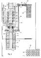
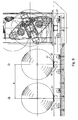
- Fig. 1 is a printing system with a device for transporting rolls of material 01 shown in a schematic view from above.
- the packaged material rolls 01 are transported by means of a suitable means of transport, for example a nip stacker, into the region of an unpacking station 03 and stored there on a roll former 04.
- the material rolls 01 are manually rolled onto a first transport carriage 27.
- the first transport carriage 27 has for this purpose at the top of a suitable trough, which is suitable for the secure storage of the rolls of material 01.
- the roll of material 01 is transported to the middle of the unpacking station 03, positioned centrally and then unpacked manually.
- the necessary splices 15 are also attached to the web start of the roll of material 01 by the operator so that the Auspackstation 03 also serves as a splice preparation station 03 at the same time.
- the web-processing machine 06 is designed in the manner of a web-fed rotary printing press 06, in which four printing couples 07 are consecutively traversed by a printing material web.
- the printing substrate can be printed, for example, four-color and two-sided and is then dried in a dryer 08.
- the web-processing machine 06 is preceded by a reel changer 09, in which two material rolls 01 can be clamped. With the roll changer 09 a flying roll change can be realized without machine downtime.
- the web-fed rotary printing press is gravure printing or
- Offset printing machine eg commercial web press
- z. Hall floor, bearings and / or roll changers and / or printing units e.g. arranged one behind the other in a plane 20 (based on the web running direction).
- a bearing 11 is provided, which is designed as an intermediate storage for storing the daily requirement of rolls of material 01.
- a first transport carriage 27 can be parked with a material roll 01 mounted thereon.
- a second trolley 27 After preparing the splices 15 on the roll of material 01 takes on the Auspackstation 03 in the raised state of the Materialrolle01, a second trolley 27, the roll of material 01 and travels with this to the transfer position to the trolley 32. There, the trolley 27 is piggybacked on the trolley 32 , By moving the second transport carriage 32, the splice-prepared material roll 01 can optionally be conveyed via a transport path 14 directly to the roll changer 09 or via the transport path 12 into the bearing 11. The decision as to whether the material roll 01 is conveyed from the unpacking station 03 directly to the reel changer 09 or into the bearing 11 falls under the control of a material supply system.
- the second transport carriage 32 with the first transport carriage 27 charged thereon and the material roll 01 loaded thereon travel via the transport path 12 into the storage 11 until an empty storage space 13 is reached.
- the first trolley 27 can be inserted into the branch path 16 of the storage bin 13.
- the second trolley 32 leaves the bearing 11 again via the transport path 12, optionally also another first trolley 27 from the Camp 11 can be taken.
- the bearing 11 is protected against unauthorized entry. On three sides of the bearing 11, the protection of a secured area, in particular a fencing formed. On the side facing the reel changer 09 of the bearing 11, a lock 18 is provided in the area safeguard 37 of the reel changer 09. In the area of the lock 18, the area protection 37 by light barriers or sensors, for. B. laser sensors that operate without contact implemented.
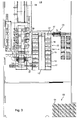
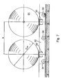
- a second system variant is shown schematically.
- This variant is different from the one in Fig. 1 illustrated variant in that between the unpacking 03 and the reel changer 09 and the bearing 11, an additional transport path 19 is provided, via which the second trolley 32 the piggyback loaded first trolley 27 and the material roll 01 mounted thereon to the reel changer 09 and the camp 11 transported.
- transport path 19 two turntables 21 are installed to the direction changes of the first transport carriage 27th between the unpacking 03 and the bearing 11 and the reel changer 09 to realize.
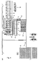
- a transport path 23 extends through the bearing 22 and thereby runs at right angles to the web running direction of the web-processing machine 06.
- the first trolley 27 along the transport path 23 passes through the entire camp 22.
- splice prepared material roll 01 either temporarily stored in the warehouse 22 or directly promoted to reel changer 09.
- the storage bins 13 of the bearing 22 are located on both sides of the transport path 12, and thus parallel to the web-processing machine 06, resulting in a very compact system configuration.
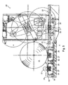
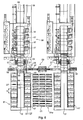
- Fig. 4 is presented a fourth variation, which is largely the in Fig. 3 corresponds to the system shown. Unlike the in Fig. 3 However, in the case of the bearing 24, only storage bins 13 are provided on the left side of the transport path 12, so that an overall even more compact system configuration is made possible. The control of the system via a control station 26th
- first transport carriages 27 are used for transporting and removing new or expired material rolls 01.
- first transport carriages 27 are, for example, rail-guided.
- the trolley 27 has four rollers 28 which roll on rails.
- To drive the trolley 27 may be provided, for example, a running under floor drag conveyor, the z. B. is designed as a circulating chain. With this necklace is the Dolly 27 connected at least temporarily.
- On a frame of the trolley 27, a trough-like shell 29 is mounted for receiving the rolls of material 01. This serving as a receptacle shell 29 protrudes from the bottom 31 of the storage room, while the first transport carriage 27 extends sunk below the bottom 31 of the storage room.
- each track sections are provided, in which the first transport carts 27 can enter with their rollers 28.
- a separate chain drive is provided in each storage place 13 to a separate chain drive.
- at least the majority of storage bins 13 have separate chain drives.
- the storage bins 13 or stitch cords 16 each receive a roll of material 01 or a transport carriage 27. But these can also record exactly 2 or more rolls of material 01.
- each second transport carriage 32 For conveying the first transport carriage 27 along the transport paths 12 and 14 are second transport carts 32.
- the frame of each second transport carriage 32 has a short track section 33, in each of which a first transport carriage 27 can enter with its rollers 28.
- the second trolleys 32 are also arranged below the floor and provided with four guided on rails rollers 34. To drive the second trolleys 32 also chain conveyor can be used.
- the second trolley 32 may in an alternative embodiment, two track sections 33; 33 'had.
- a distance a of the two track sections 33; 33 ' is greater than a maximum diameter D max of the material rolls 01 to be transported.
- the distance a of the two track sections 33; 33 'of the trolley 32 equal to the distance a of the track sections 33; 33 'of the stitch cords 16 of the storage bins 13.
- At least one of the transport carriage 27 may carry an adapter for receiving residual roles.
- the longitudinal direction and web running direction of the web-processing machine are substantially in the same direction.
- At least one printing unit 07, the reel changer 09 and the storage bins 13 are arranged approximately in a common plane 20. An arrangement of all printing units 07 in a common plane 20 is advantageous.
- the processing machine furthermore has a single reel changer.
- the transport path of the second transport carriage 32 and the longitudinal axis 10 of a dryer 08 of the processing machine are arranged so that they lie in alignment, or are arranged to extend parallel offset.
- the reference point is used in the printing units 07 and the reel changer 09, the lower edge of the respective side frame and, at the storage bins 13 receiving the transport carriage 27.
- the common plane 20 is the building floor.
- the device for transporting material rolls works taking into account the specific roll data recorded in the transport or preparation process, such as, for example, Barcode and / or roll width and / or roll status and / or weights (gross, net weight 1, net weight 2) and / or gluing time and / or run length, etc.
- the data is maintained and managed in the respective process steps.
- the evaluation and storage for further exploitation of this data via a suitable management system. It is also possible to make use of the role data acquired during and after the unwinding process via the reel splicer (s) for transfer to the specific data record of the reel and its allocation.
- the device is suitable to act in the transport, preparation and data management processes partial or mulchen of the production process and to manage accordingly.
- An expression of this are the with the transports of sub-roles z. B. associated with adapters operations. Also, for example, the management of the adapter (with and without roles) and all necessary operations for this purpose can be integrated.
- Another characteristic feature of such a device is the use of multiple trolleys per storage position and all operations required for this purpose.
- a variant is also the use of a transfer table with several rail tracks, which allows further optimizations of said device.
- Another possible expression is the transport of the sleeve container and its data content to certain, for example, freely selectable positions in the warehouse or to transport other possible positions in said device. Also included here can be other data transfers to the management system or to further evaluation units of the machine or the production preparation.
Landscapes
- Replacement Of Web Rolls (AREA)
- Warehouses Or Storage Devices (AREA)
- Winding, Rewinding, Material Storage Devices (AREA)
Abstract
Claims (78)
- Dispositif de transport de rouleaux de matière (01), les rouleaux de matière (01) étant disposés sur un premier chariot de transport (27) et ce chariot de transport (27) étant disposé sur un deuxième chariot de transport (32), le deuxième chariot de transport (32) se déplaçant entre un magasin de stockage (11 ; 22 ; 24) comprenant plusieurs emplacements de stockage (13) et un changeur de rouleau (09) d'une machine (06) travaillant une bande, le deuxième chariot de transport (32), avec le premier chariot de transport (27) et le rouleau de matière (01) monté dessus, se déplaçant jusqu'à une position de mise en rayonnage et/ou de déchargement du changeur de rouleau (09), caractérisé en ce qu'au moins deux des emplacements de stockage (13), disposés directement les uns derrière les autres dans la direction longitudinale de la machine (06) travaillant une bande, et/ou des tronçons de prélèvement (16) appartenant aux emplacements de stockage (13), présentent un espacement (a) de valeur telle que deux rouleaux de matière (01) neufs sont susceptibles d'être stockés ou emmagasinés.
- Dispositif selon la revendication 1, caractérisé en ce que les rouleaux de matière (01) situés dans les emplacements de stockage (13) sont montés sur des premiers chariots de transport (27).
- Dispositif selon la revendication 1, caractérisé en ce que, en se référant à la direction de transport des rouleaux de matière (01), les emplacements de stockage (13) sont disposés en aval d'un poste de préparation (03) pour l'application manuelle ou mécanisée d'éléments adhésifs.
- Dispositif selon la revendication 1, caractérisé en ce que plusieurs emplacements de stockage (13) pour des rouleaux de matière (01) sont chaque fois disposés sur les deux côtés du chemin de transport (12).
- Dispositif selon la revendication 1, caractérisé en ce que le magasin de stockage (11, 22, 24) est réalisé à la manière d'un magasin de stockage intermédiaire, en particulier à la manière d'un magasin journalier.
- Dispositif selon la revendication 1, caractérisé en ce qu'au moins deux rouleaux de matière (01), déjà déballés et préparés pour le changement de rouleau avec des emplacements adhésifs (15), sont montés aux emplacements de stockage (13) du magasin de stockage (11, 22, 24).
- Dispositif selon la revendication 6, caractérisé en ce que tous les rouleaux de matière (01) neufs sont préparés avec des emplacements adhésifs (15).
- Dispositif selon la revendication 1, caractérisé en ce que les premiers chariots de transport (27) sont susceptibles d'être au choix stationnés en chaque emplacement de stockage (13) du magasin (11, 22, 24).
- Dispositif selon la revendication 1 ou 2, caractérisé en ce qu'au moins un premier chariot de transport (27) situé sur un chemin de transport (19) est également déplaçable dans un poste de déballage (03), pour déballer les rouleaux de matière (01).
- Dispositif selon la revendication 9, caractérisé en ce qu'au moins un premier chariot de transport (27) situé sur un chemin de transport (19) est également déplaçable dans un poste de préparation d'emplacements adhésifs (03), pour préparer les emplacements adhésifs (15) sur le rouleau de matière (01).
- Dispositif selon la revendication 10, caractérisé en ce que le poste de préparation d'emplacements adhésifs (03) est en même temps utilisable comme poste de déballage (03).
- Dispositif selon la revendication 1, caractérisé en ce qu'un chemin de transport (12), sur lequel le deuxième chariot de transport (32) est déplaçable, est prévu dans le magasin de stockage (11), dans le prolongement virtuel de la direction de défilement de bande de la machine (06) travaillant une bande.
- Dispositif selon la revendication 1, caractérisé en ce qu'un chemin de transport (12), sur lequel le deuxième chariot de transport (32) est déplaçable, est prévu dans le magasin de stockage (11), parallèlement au prolongement de la direction de défilement de bande de la machine (06) travaillant une bande.
- Dispositif selon la revendication 1, caractérisé en ce que les emplacements de stockage (13) sont susceptibles d'être approchés par des tronçons de prélèvement (16), s'étendant en particulier perpendiculairement au chemin de transport (11).
- Dispositif selon la revendication 1, caractérisé en ce que des emplacements de stockage (13) sont prévus sur un seul côté d'un chemin de transport (12).
- Dispositif selon la revendication 1, caractérisé en ce qu'un système de mesure de course de déplacement, servant au positionnement exact du deuxième chariot de transport (32), est prévu le long d'au moins des tronçons déterminés d'un chemin de transport (12).
- Dispositif selon la revendication 1, caractérisé en ce que le magasin de stockage (11, 22, 24) est sécurisé contre toute intrusion non autorisée au moyen d'une zone (17 ; 37) sécurisée placée aux limites du magasin de stockage (11, 22, 24).
- Dispositif selon la revendication 17, caractérisé en ce que la zone (17) sécurisée du magasin de stockage (11, 24) est formée, par tronçons, par mise en place d'une clôture.
- Dispositif selon la revendication 17 ou 18, caractérisé en ce que la zone (17) sécurisée du magasin de stockage (11) est formée, par tronçons, par la sécurisation de zone (37) du changeur de rouleau (09).
- Dispositif selon la revendication 17, 18 ou 19, caractérisé en ce qu'au moins un sas (18), pour l'infiltration et/ou l'exfiltration de rouleaux de matière (01), est prévu dans la sécurisation de zone (37).
- Dispositif selon la revendication 20, caractérisé en ce que, dans la zone du sas (18), le magasin de stockage (11) est sécurisé contre toute intrusion non autorisée par des barrières photoélectriques ou des capteurs à ultra-sons.
- Dispositif selon la revendication 21, caractérisé en ce que plusieurs barrières photoélectriques ou capteurs à ultra-sons, disposés à des hauteurs différentes, sont prévus.
- Dispositif selon l'une des revendications 1 à 22, caractérisé en ce que plusieurs postes d'usinage (07), disposés les uns derrière les autres en direction longitudinale, sont prévus dans la machine (06) travaillant une bande.
- Dispositif selon l'une des revendications 1 à 23, caractérisé en ce qu'au moins un poste d'usinage (07) est réalisé sous forme de groupe d'impression (07) d'une machine (06) travaillant une bande, dans la machine (06) travaillant une bande.
- Dispositif selon la revendication 24, caractérisé en ce que la machine (06) travaillant une bande présente une allure de bande horizontale à travers les groupes d'impression (07).
- Dispositif selon la revendication 1, caractérisé en ce que le magasin de stockage (11, 22, 24) est réalisé sous forme de magasin de stockage FIFO (premier entré - premier sorti).
- Dispositif selon la revendication 1, caractérisé en ce qu'un pupitre de commande est prévu pour la manoeuvre de la machine travaillant une bande, et le magasin de stockage (11, 22, 24) est disposé à côté du pupitre de commande.
- Dispositif selon la revendication 1, caractérisé en ce que le premier chariot de transport (27) présente des galets déroulement (28) et se déplace sur des rails.
- Dispositif selon la revendication 1, caractérisé en ce que le deuxième chariot de transport (32) présente des galets déroulement (34) et se déplace sur des rails.
- Dispositif selon la revendication 29, caractérisé en ce qu'un bâti du deuxième chariot de transport (32) présente un tronçon de voie ferrée (33) court, dans lequel pénètre le premier chariot de transport (27).
- Dispositif selon la revendication 28 ou 29, caractérisé en ce que l'entraînement des chariots de transport (27 ; 32) s'effectue par transporteur à chaîne.
- Dispositif selon la revendication 30, caractérisé en ce que le deuxième chariot de transport (32) présente deux tronçons de voie ferrée (33 ; 33') écartés d'une distance d'espacement (a).
- Dispositif selon la revendication 32, caractérisé en ce que la distance d'espacement (a) des deux tronçons de voie ferrée (33 ; 33') est plus grande qu'un diamètre maximal (Dmax) d'un rouleau de matière (01) à transporter.
- Dispositif selon la revendication 1, caractérisé en ce qu'au moins une partie des emplacements de stockage (13) et/ou des tronçons de prélèvement (16) appartenant aux emplacements de stockage (13) reçoivent un chariot de transport (27) unique.
- Dispositif selon la revendication 1 , caractérisé en ce que la pluralité des emplacements de stockage (13) et/ou des tronçons de prélèvement (16) appartenant aux emplacements de stockage (13) reçoivent un chariot de transport (27) unique.
- Dispositif selon la revendication 1, caractérisé en ce que tous les emplacements de stockage (13) et/ou les tronçons de prélèvement (16) appartenant aux emplacements de stockage (13) reçoivent un chariot de transport (27) unique.
- Dispositif selon la revendication 36, caractérisé en ce qu'au moins une partie des emplacements de stockage (13) et/ou des tronçons de prélèvement (16) appartenant aux emplacements de stockage (13) reçoivent deux chariots de transport (27).
- Dispositif selon la revendication 37, caractérisé en ce que la pluralité des emplacements de stockage (13) et/ou des tronçons de prélèvement (16) appartenant aux emplacements de stockage (13) reçoivent deux chariots de transport (27).
- Dispositif selon la revendication 38, caractérisé en ce que tous les emplacements de stockage (13) et/ou les tronçons de prélèvement (16) appartenant aux emplacements de stockage (13) reçoivent deux chariots de transport (27).
- Dispositif selon la revendication 39, caractérisé en ce qu'au moins une partie des emplacements de stockage (13) et/ou des tronçons de prélèvement (16) appartenant aux emplacements de stockage (13) reçoivent plus de deux chariots de transport (27).
- Dispositif selon la revendication 40, caractérisé en ce que la pluralité des emplacements de stockage (13) et/ou des tronçons de prélèvement (16) appartenant aux emplacements de stockage (13) reçoivent plus de deux chariots de transport (27).
- Dispositif selon la revendication 41, caractérisé en ce que tous les emplacements de stockage (13) et/ou les tronçons de prélèvement (16) appartenant aux emplacements de stockage (13) reçoivent plus de deux chariots de transport (27).
- Dispositif selon la revendication 1 ou 2, caractérisé en ce qu'au moins un chariot de transport (27) porte un adaptateur pour recevoir un rouleau partiel.
- Dispositif selon la revendication 1, caractérisé en ce que deux magasins de stockage (11 ; 11') sont disposés avec chaque fois un deuxième chariot de transporteur (32).
- Dispositif selon la revendication 44, caractérisé en ce que les chemins de transport (14) des deux chariots de transport (32) sont disposés en s'étendant parallèlement.
- Dispositif selon la revendication 44, caractérisé en ce que les deux magasins de stockage (11 ; 11') sont reliés au moyen d'une voie ferrée.
- Dispositif selon la revendication 44, caractérisé en ce qu'un poste de préparation (03) pour l'application d'éléments adhésifs est disposé entre les deux magasins de stockage (11 ; 11').
- Dispositif selon la revendication 1, 3 ou 44, caractérisé en ce que le deuxième chariot de transport (32) est disposé en transportant les rouleaux de matière (01), dont l'adhésif a été préparé, dans le magasin de stockage (11 ; 11').
- Dispositif selon la revendication 1, caractérisé en ce qu'au moins deux des emplacements de stockage (13), disposés directement les uns derrière les autres dans la direction longitudinale de la machine (06) travaillant une bande, et/ou des tronçons de prélèvement (16) appartenant aux emplacements de stockage (13) présentent une distance d'espacement (a) plus grande qu'un diamètre maximal (Dmax) du rouleau de matière (01) à transporter.
- Dispositif selon la revendication 1, caractérisé en ce que la pluralité des emplacements de stockage (13), disposés directement les uns derrière les autres dans la direction longitudinale de la machine travaillant une bande, et/ou des tronçons de prélèvement (16) appartenant aux emplacements de stockage (13) présentent une distance d'espacement (a) plus grande qu'un diamètre maximal (Dmax) du rouleau de matière (01) à transporter.
- Dispositif selon la revendication 1, caractérisé en ce que la pluralité des emplacements de stockage (13), disposés directement les uns derrière les autres dans la direction longitudinale de la machine (06) travaillant une bande, et/ou des tronçons de prélèvement (16) appartenant aux emplacements de stockage (13) présentent une distance d'espacement (a) de valeur telle que deux rouleaux de matière (01) neufs sont susceptibles d'être stockés ou emmagasinés.
- Dispositif selon la revendication 1 , caractérisé en ce que la totalité des emplacements de stockage (13), disposés directement les uns derrière les autres dans la direction longitudinale de la machine (06) travaillant une bande, et/ou des tronçons de prélèvement (16) appartenant aux emplacements de stockage (13) présentent une distance d'espacement (a) plus grande qu'un diamètre maximal (Dmax) du rouleau de matière (01) à transporter.
- Dispositif selon la revendication 1, caractérisé en ce que la totalité des emplacements de stockage (13), disposés directement les uns derrière les autres dans la direction longitudinale de la machine (06) travaillant une bande, et/ou des tronçons de prélèvement (16) appartenant aux emplacements de stockage (13) présentent une distance d'espacement (a) de valeur telle que deux rouleaux de matière (01) neufs sont susceptibles d'être stockés ou sont emmagasinés.
- Dispositif selon la revendication 4, caractérisé en ce qu'au moins trois emplacements de stockage (13) pour des rouleaux de matière (01) sont chaque fois disposés sur les deux côtés du chemin de transport (12).
- Dispositif selon la revendication 1, caractérisé en ce que des rouleaux de matière (01) neufs sont susceptibles d'être stockés ou sont emmagasinés sur au moins deux des emplacements de stockage (13), disposés directement les uns derrière les autres dans la direction longitudinale de la machine (06) travaillant une bande.
- Dispositif selon la revendication 1, caractérisé en ce que des rouleaux de matière (01) neufs sont susceptibles d'être stockés ou sont emmagasinés sur la pluralité des emplacements de stockage (13), disposés directement les uns derrière les autres dans la direction longitudinale de la machine (06) travaillant une bande.
- Dispositif selon la revendication 1, caractérisé en ce que des rouleaux de matière (01) neufs sont susceptibles d'être stockés ou sont emmagasinés sur tous les emplacements de stockage (13), disposés directement les uns derrière les autres dans la direction longitudinale de la machine (06) travaillant une bande.
- Dispositif selon la revendication 1, caractérisé en ce que des rouleaux de matière (01) à diamètre maximal (Dmax) sont susceptibles d'être stockés sur au moins deux des emplacements de stockage (13), disposés directement les uns derrière les autres dans la direction longitudinale de la machine (06) travaillant une bande.
- Dispositif selon la revendication 1, caractérisé en ce que des rouleaux de matière (01) à diamètre maximal (Dmax) sont susceptibles d'être stockés sur la pluralité des emplacements de stockage (13), disposés directement les uns derrière les autres dans la direction longitudinale de la machine (06) travaillant une bande.
- Dispositif selon la revendication 1, caractérisé en ce que des rouleaux de matière (01) à diamètre maximal (Dmax) sont susceptibles d'être stockés sur la totalité des emplacements de stockage (13), disposés directement les uns derrière les autres dans la direction longitudinale de la machine (06) travaillant une bande.
- Dispositif selon la revendication 51, 53 ou 55 à 57, caractérisé en ce que les rouleaux de matière (01) neufs sont munis d'adhésifs (15).
- Dispositif selon la revendication 23, caractérisé en ce que la direction longitudinale et la direction de défilement de bande de la machine (06) travaillant une bande s'étendent sensiblement dans la même direction.
- Dispositif selon la revendication 1, caractérisé en ce qu'aucun plateau tournant pour les chariots de transports (27) n'est disposé entre les emplacements de stockage (13) et le changeur de rouleau (09).
- Dispositif selon la revendication 3, caractérisé en ce qu'aucun plateau tournant pour les chariots de transports (27) n'est disposé entre les emplacements de stockage (13) et le poste de préparation (03) pour l'application d'éléments adhésifs.
- Dispositif selon la revendication 24, caractérisé en ce qu'au moins un groupe d'impression (07), le changeur de rouleau (09) et les emplacements de stockage (13) sont disposés à peu près dans un plan (20) commun.
- Dispositif selon la revendication 65, caractérisé en ce que tous les groupes d'impression (07) sont disposés dans un plan (20) commun.
- Dispositif selon la revendication 1, caractérisé en ce que la machine (06) travaillant une bande présente un changeur de rouleau (09) unique.
- Dispositif selon la revendication 1 ou 3, caractérisé en ce que le chemin de transport (12) du deuxième chariot de transport (32) et l'axe longitudinal (10) d'un sécheur (08) de la machine (06) travaillant une bande sont alignés.
- Dispositif selon la revendication 1 ou 3, caractérisé en ce que le chemin de transport (12) du deuxième chariot de transport (32) et l'axe longitudinal (10) d'un sécheur (08) de la machine (06) travaillant une bande sont disposés parallèlement décalés.
- Dispositif selon la revendication 1, caractérisé en ce que, concernant la pluralité des emplacements de stockage (13), chaque emplacement de stockage (13) présente un entraînement propre pour le transport des rouleaux de matière (01).
- Dispositif selon la revendication 1 ou 2, caractérisé en ce que, concernant la pluralité des emplacements de stockage (13), chaque emplacement de stockage (13) présente un système de transport en sous-sol propre pour les chariots de transport (27).
- Dispositif selon la revendication 71, caractérisé en ce que le système de transport en sous-sol présente un moyen de propulsion circulant.
- Dispositif selon la revendication 72, caractérisé en ce que le moyen de propulsion est réalisé sous forme de chaîne.
- Dispositif selon la revendication 1 ou 2, caractérisé en ce que chaque premier chariot de transport (27) présente un entraînement propre.
- Dispositif selon la revendication 70, caractérisé en ce que tous les emplacements de stockage (13) présentent un entraînement propre.
- Dispositif selon la revendication 71, caractérisé en ce que tous les emplacements de stockage (13) présentent un système de transport en sous-sol.
- Dispositif selon la revendication 1, caractérisé en ce que le deuxième chariot de transport (32) présente un entraînement propre.
- Dispositif selon la revendication 77, caractérisé en ce que l'entraînement du deuxième chariot de transport (32) est actionnable indépendamment des entraînements des premiers chariots de transport (27).
Priority Applications (2)
| Application Number | Priority Date | Filing Date | Title |
|---|---|---|---|
| EP07104342A EP1801057A1 (fr) | 2004-02-23 | 2005-02-09 | Construction de cadre pour un composant composé de barres de cadres |
| EP09168172A EP2113478A1 (fr) | 2004-02-23 | 2005-02-09 | Dispositif pour le transport de rouleaux de matériau |
Applications Claiming Priority (3)
| Application Number | Priority Date | Filing Date | Title |
|---|---|---|---|
| DE102004008771 | 2004-02-23 | ||
| DE102004021605A DE102004021605B4 (de) | 2004-02-23 | 2004-05-03 | Vorrichtung zum Transport von Materialrollen |
| PCT/EP2005/050569 WO2005080241A2 (fr) | 2004-02-23 | 2005-02-09 | Dispositifs de transport de rouleaux de matiere |
Related Child Applications (4)
| Application Number | Title | Priority Date | Filing Date |
|---|---|---|---|
| EP07104342A Division EP1801057A1 (fr) | 2004-02-23 | 2005-02-09 | Construction de cadre pour un composant composé de barres de cadres |
| EP09168172A Division EP2113478A1 (fr) | 2004-02-23 | 2005-02-09 | Dispositif pour le transport de rouleaux de matériau |
| EP07104342.6 Division-Into | 2007-03-16 | ||
| EP09168172.6 Division-Into | 2009-08-19 |
Publications (2)
| Publication Number | Publication Date |
|---|---|
| EP1718552A2 EP1718552A2 (fr) | 2006-11-08 |
| EP1718552B1 true EP1718552B1 (fr) | 2011-02-02 |
Family
ID=34888809
Family Applications (1)
| Application Number | Title | Priority Date | Filing Date |
|---|---|---|---|
| EP05716652A Expired - Lifetime EP1718552B1 (fr) | 2004-02-23 | 2005-02-09 | Dispositif de transport de rouleaux de matiere |
Country Status (5)
| Country | Link |
|---|---|
| US (1) | US8011871B2 (fr) |
| EP (1) | EP1718552B1 (fr) |
| JP (1) | JP2007533565A (fr) |
| BR (1) | BRPI0507951A (fr) |
| WO (1) | WO2005080241A2 (fr) |
Families Citing this family (20)
| Publication number | Priority date | Publication date | Assignee | Title |
|---|---|---|---|---|
| DE102006008104A1 (de) * | 2006-02-20 | 2007-10-18 | Koenig & Bauer Aktiengesellschaft | Vorrichtung zur Abedeckung eines Gefahrenbereiches an einem Rollenwechsler und ein Vefahren zur Steuerung einer Vorrichtung |
| DE102006019595B3 (de) * | 2006-04-27 | 2007-12-13 | Koenig & Bauer Aktiengesellschaft | Gefahrenbereichsabsicherung an einem Rollenwechsler mit einer Trittmatte |
| DE102006048675B3 (de) * | 2006-10-14 | 2007-12-27 | Koenig & Bauer Aktiengesellschaft | Zwischenlager für einer bahnverarbeitenden Maschine zuzuführende Materialrollen |
| DE102007025800B4 (de) | 2007-06-02 | 2013-10-17 | Koenig & Bauer Aktiengesellschaft | Gefahrenbereichsabsicherung für den Bereich der automatischen Rollenbestückung an einem Rollenwechsler |
| DE102007028683A1 (de) * | 2007-06-21 | 2008-12-24 | Maschinenfabrik Wifag | Rollenwechselvorrichtung mit Transportwagensystem |
| DE102008042813A1 (de) * | 2008-10-14 | 2010-04-22 | Koenig & Bauer Aktiengesellschaft | Gefahrenbereichsabsicherung für den Bereich der automatischen Rollenbestückung an einem Rollenwechsler |
| DE102009046069A1 (de) * | 2009-10-28 | 2011-05-12 | Manroland Ag | Fördersystem für eine Rotationsdruckmaschine |
| PL2335910T3 (pl) * | 2009-12-18 | 2018-09-28 | Lm Wind Power International Technology Ii Aps | Urządzenie załadunkowe i sposób załadunku rolek materiału arkuszowego na bazie włókien do jednostki nakładającej |
| DE102010001014A1 (de) | 2010-01-19 | 2011-09-08 | Koenig & Bauer Aktiengesellschaft | Rollenwechsler mit einer Absicherung eines Sicherheitsbereiches |
| CN102858666B (zh) | 2010-04-28 | 2015-11-25 | 柯尼格及包尔公开股份有限公司 | 具有安全装置的换卷器以及用于使用具有安全装置的换卷器的方法 |
| DE102010031650A1 (de) | 2010-07-22 | 2012-01-26 | Koenig & Bauer Aktiengesellschaft | Rollenwechsler mit Sicherheitseinrichtung |
| DE102010028289B4 (de) | 2010-04-28 | 2013-11-28 | Koenig & Bauer Aktiengesellschaft | Rollenwechsler mit Sicherheitseinrichtung |
| EP2563701B1 (fr) | 2010-04-28 | 2016-06-29 | Koenig & Bauer AG | Changeur de bobines pourvu d'un dispositif de sécurité et procédé d'utilisation d'un changeur de bobines pourvu d'un dispositif de sécurité |
| DE102010028292B4 (de) | 2010-04-28 | 2013-09-05 | Koenig & Bauer Aktiengesellschaft | Verfahren zur Korrektur einer Ausrichtung einer ersten Rolle relativ zu einem Rollenwechsler und ein Rollenwechsler mit Schutzeinrichtung |
| FI126344B (en) * | 2012-05-22 | 2016-10-14 | Upm Raflatac Oy | Method and arrangement for handling narrow rolls |
| DE102012211708B4 (de) | 2012-07-05 | 2015-07-09 | Koenig & Bauer Aktiengesellschaft | Rollenversorgungssystem einer Rollendruckmaschine, Rollendruckmaschine sowie Verfahren zur Bedienung eines Rollenversorgungssystems einer Rollendruckmaschine |
| JP5926403B2 (ja) * | 2012-12-25 | 2016-05-25 | 平田機工株式会社 | 搬送システム |
| DE102013226022B4 (de) * | 2013-12-16 | 2017-06-14 | Koenig & Bauer Ag | Verfahren zum Befördern eines Bedruckstoffgebindes, Bearbeitungsaggregat eines Bedruckstoffversorgungssystems sowie Bedruckstoffversorgungssystem |
| DE102017211828A1 (de) * | 2017-07-11 | 2019-01-17 | Koenig & Bauer Ag | Druckmaschine mit einem Rollenabwickler sowie Verfahren zur Handhabung von Rollen bahnförmigen Material |
| KR102658024B1 (ko) * | 2021-05-07 | 2024-04-15 | 삼성에스디에스 주식회사 | 원통형 자재 보관 장치 및 그 장치에서 수행되는 방법 |
Family Cites Families (22)
| Publication number | Priority date | Publication date | Assignee | Title |
|---|---|---|---|---|
| DE2944265A1 (de) * | 1979-11-02 | 1982-03-25 | Jagenberg-Werke AG, 4000 Düsseldorf | Vorrichtung zum mehrfachabrollen von warenbahnen |
| US4537368A (en) * | 1984-05-01 | 1985-08-27 | Carborundum Abrasives Company | Pendulum roll loader |
| JPH0768000B2 (ja) | 1985-12-28 | 1995-07-26 | 大日本印刷株式会社 | 印刷機の給紙部 |
| FI80862C (fi) * | 1986-11-18 | 1990-08-10 | Kone Oy | Anordning foer hantering av pappersrullar i en anlaeggning, saosom tryckeri. |
| JPH0786058B2 (ja) | 1987-03-28 | 1995-09-20 | 大日本印刷株式会社 | 印刷機の給紙部への搬送装置 |
| DE3910444C3 (de) * | 1989-03-31 | 1998-10-22 | Wifag Maschf | Automatische Anlage zum Einbringen von Papierrollen in die Rollenständer einer Rollenrotationsdruckmaschine |
| US5076751A (en) * | 1990-03-23 | 1991-12-31 | Jervis B. Webb Company | Reelroom newsprint roll handling apparatus and method |
| JPH04197903A (ja) * | 1990-11-28 | 1992-07-17 | Mitsubishi Heavy Ind Ltd | リールの自動払い出し方法 |
| DE29516155U1 (de) | 1995-10-11 | 1995-12-07 | Hörmann Logistik GmbH, 80992 München | Regalsystem |
| DE29519942U1 (de) | 1995-12-18 | 1996-04-25 | Bruckbauer, Siegfried, 93138 Lappersdorf | Hochregal-Lager sowie Sicherheits-Rolladen für ein solches Hochregal-Lager |
| DE19637771C2 (de) * | 1996-09-16 | 2002-01-24 | Koenig & Bauer Ag | Transportwagen |
| DE19637772A1 (de) * | 1996-09-16 | 1998-03-26 | Koenig & Bauer Albert Ag | Verfahren zum Transport von Rollen zu einem Rollenwechsler |
| DE19637770A1 (de) * | 1996-09-16 | 1998-03-19 | Koenig & Bauer Albert Ag | Verfahren und Anlage zum automatischen Zu- und Abführen von Rollen |
| DE59706549D1 (de) * | 1996-12-21 | 2002-04-11 | Koenig & Bauer Ag | Verfahren zum Lageerfassen und Positionieren einer Vorratsbahnrolle |
| DE10035788C1 (de) * | 2000-07-22 | 2002-03-14 | Koenig & Bauer Ag | Verfahren und Vorrichtung zur Regelung einer Bahnspannung in einer Rotationsdruckmaschine |
| DE10150810B4 (de) * | 2001-10-15 | 2011-01-13 | Wifag Maschinenfabrik Ag | Rollenwechsler und Verfahren zum Ausachsen einer Restrolle |
| GB2382340B (en) | 2001-11-26 | 2003-11-19 | Sca Hygiene Prod Gmbh | Method and transportation device for transporting a product from a remote place to a converting machine |
| EP1329397A1 (fr) | 2002-01-18 | 2003-07-23 | Westfalia WST Systemtechnik GmbH & Co. KG | Dispositif de transport |
| DE10213459A1 (de) | 2002-03-26 | 2003-10-30 | Koenig & Bauer Ag | Gütertransportsystem mit einem Schienennetz und ein Verfahren zum Betreiben dieses Gütertransportsystems |
| US6948901B2 (en) * | 2002-11-12 | 2005-09-27 | Metso Paper Ag | Paper roll storage and handling installation and method for storing and handling paper rolls |
| DE20307581U1 (de) | 2003-05-15 | 2003-09-25 | Voith Paper Patent GmbH, 89522 Heidenheim | Wickelmaschine zum kontinuierlichen Aufwickeln einer laufenden Materialbahn |
| ATE385981T1 (de) * | 2004-07-02 | 2008-03-15 | Metso Paper Ag | Anlage zur zuführung von papierrollen zu einem rollenständer und verfahren zu ihrem betrieb |
-
2005
- 2005-02-09 WO PCT/EP2005/050569 patent/WO2005080241A2/fr not_active Ceased
- 2005-02-09 BR BRPI0507951-9A patent/BRPI0507951A/pt not_active IP Right Cessation
- 2005-02-09 JP JP2006523022A patent/JP2007533565A/ja active Pending
- 2005-02-09 US US10/590,390 patent/US8011871B2/en not_active Expired - Fee Related
- 2005-02-09 EP EP05716652A patent/EP1718552B1/fr not_active Expired - Lifetime
Also Published As
| Publication number | Publication date |
|---|---|
| BRPI0507951A (pt) | 2007-07-24 |
| WO2005080241A3 (fr) | 2006-02-02 |
| JP2007533565A (ja) | 2007-11-22 |
| EP1718552A2 (fr) | 2006-11-08 |
| US20070170298A1 (en) | 2007-07-26 |
| US8011871B2 (en) | 2011-09-06 |
| WO2005080241A2 (fr) | 2005-09-01 |
Similar Documents
| Publication | Publication Date | Title |
|---|---|---|
| EP1718552B1 (fr) | Dispositif de transport de rouleaux de matiere | |
| EP0925246B2 (fr) | Procede pour le transport de rouleaux vers un changeur de rouleaux | |
| EP0925247B2 (fr) | Chariot transporteur pour rouleaux de papier | |
| EP0261508B1 (fr) | Dispositif pour le transport de bobines de papier d'emballage vers les machines d'emballage | |
| EP0925248B1 (fr) | Installation pour l'insertion et l'enlevement automatiques de rouleaux | |
| WO2013004695A1 (fr) | Système et procédé d'entrée d'un produit à stocker dans un rayon et de sortie hors du rayon | |
| DE102017205133A1 (de) | Verfahren und Vorrichtung zur Entnahme einer Materialbahnrolle von einem Rollenträger einer materialbahnverarbeitenden Maschine | |
| DE19606554C1 (de) | Bodenverfahrbare Vorrichtung für den Transport von zylindrischen Körpern, insbesondere von Papier- und Papierollen wie sie in Zeitungs-, Magazin- und Buchdruckereien verwendet werden | |
| EP1892207A2 (fr) | Dispositif destiné à la répartition et/ou le trie de rouleaux de matériau et leur transmission et un procédé de transport de rouleaux de matériau | |
| EP1586522B1 (fr) | Procédé de fonctionnement d'un système de transport | |
| EP1801057A1 (fr) | Construction de cadre pour un composant composé de barres de cadres | |
| EP1632447B9 (fr) | Appareil de commande d'entrepôt et installation pour préparer et entreposer des bobines de papier et amener celles-ci à au moins un porte-bobine et procédé pour son fonctionnement. | |
| EP1733980B1 (fr) | Dispositif de transport d'au moins une bobine de matériau | |
| DE4416213A1 (de) | Anlage zum Lagern und Einbringen von Papierrollen in mit fliegendem Rollenwechsel arbeitende Rollenwechsler einer Rollendruckmaschine | |
| EP1612169B1 (fr) | Installation d'alimentation d'un porte-bobine en bobines de papier et procédé pour son fonctionnement | |
| DE102016218108B4 (de) | Verfahren und Vorrichtung zur Entnahme einer in einer Rollendruckmaschine bedruckten und ausgangsseitig der Rollendruckmaschine an einem Aufwickler aufgewickelten Produktrolle | |
| DE602004006202T2 (de) | Verfahren und Vorrichtung zum Handhaben von Lasten | |
| DE102017206036B4 (de) | Verfahren zum Betrieb eines Bahnaufwicklers, Bahnaufwickler sowie Maschine mit einem derartigen Bahnaufwickler | |
| DE102016218107B4 (de) | Vorrichtung zur Überwachung des Ladezustandes eines auf einer Transportstrecke eines Rollentransportsystems bewegbaren Transportmittels | |
| DE19611494A1 (de) | Abwickelsystem für Wickelrollen, insbesondere aus Papier oder Karton | |
| DE102016218106B4 (de) | Verfahren und Vorrichtung zur Entnahme einer Materialbahnrolle von einem Rollenträger einer materialbahnverarbeitenden Maschine | |
| EP1491476A2 (fr) | Installation de transport pour l'alimentation des rouleaux de papier à des porte-bobines et procédé pour le fonctionnement | |
| EP1491475A1 (fr) | Installation de transport pour l'alimentation de bobines à de portes bobines et chariot de bobines | |
| DE102008029965A1 (de) | Rollenwechsleranordnung für eine Rollenrotationsdruckmaschine | |
| DE102021116550A1 (de) | Vorrichtung und Verfahren zum Transport von Rollen |
Legal Events
| Date | Code | Title | Description |
|---|---|---|---|
| PUAI | Public reference made under article 153(3) epc to a published international application that has entered the european phase |
Free format text: ORIGINAL CODE: 0009012 |
|
| 17P | Request for examination filed |
Effective date: 20060331 |
|
| AK | Designated contracting states |
Kind code of ref document: A2 Designated state(s): AT BE BG CH CY CZ DE DK EE ES FI FR GB GR HU IE IS IT LI LT LU MC NL PL PT RO SE SI SK TR |
|
| 17Q | First examination report despatched |
Effective date: 20070308 |
|
| DAX | Request for extension of the european patent (deleted) | ||
| GRAP | Despatch of communication of intention to grant a patent |
Free format text: ORIGINAL CODE: EPIDOSNIGR1 |
|
| GRAS | Grant fee paid |
Free format text: ORIGINAL CODE: EPIDOSNIGR3 |
|
| GRAA | (expected) grant |
Free format text: ORIGINAL CODE: 0009210 |
|
| RTI1 | Title (correction) |
Free format text: DEVICE FOR TRANSPORTING REELS OF MATERIAL |
|
| AK | Designated contracting states |
Kind code of ref document: B1 Designated state(s): AT BE BG CH CY CZ DE DK EE ES FI FR GB GR HU IE IS IT LI LT LU MC NL PL PT RO SE SI SK TR |
|
| REG | Reference to a national code |
Ref country code: GB Ref legal event code: FG4D Free format text: NOT ENGLISH |
|
| REG | Reference to a national code |
Ref country code: CH Ref legal event code: EP |
|
| REG | Reference to a national code |
Ref country code: IE Ref legal event code: FG4D Free format text: LANGUAGE OF EP DOCUMENT: GERMAN |
|
| REF | Corresponds to: |
Ref document number: 502005010931 Country of ref document: DE Date of ref document: 20110317 Kind code of ref document: P |
|
| REG | Reference to a national code |
Ref country code: DE Ref legal event code: R096 Ref document number: 502005010931 Country of ref document: DE Effective date: 20110317 |
|
| REG | Reference to a national code |
Ref country code: ES Ref legal event code: FG2A Ref document number: 2356742 Country of ref document: ES Kind code of ref document: T3 Effective date: 20110412 |
|
| REG | Reference to a national code |
Ref country code: NL Ref legal event code: VDEP Effective date: 20110202 |
|
| LTIE | Lt: invalidation of european patent or patent extension |
Effective date: 20110202 |
|
| PG25 | Lapsed in a contracting state [announced via postgrant information from national office to epo] |
Ref country code: GR Free format text: LAPSE BECAUSE OF FAILURE TO SUBMIT A TRANSLATION OF THE DESCRIPTION OR TO PAY THE FEE WITHIN THE PRESCRIBED TIME-LIMIT Effective date: 20110503 Ref country code: PT Free format text: LAPSE BECAUSE OF FAILURE TO SUBMIT A TRANSLATION OF THE DESCRIPTION OR TO PAY THE FEE WITHIN THE PRESCRIBED TIME-LIMIT Effective date: 20110602 Ref country code: SE Free format text: LAPSE BECAUSE OF FAILURE TO SUBMIT A TRANSLATION OF THE DESCRIPTION OR TO PAY THE FEE WITHIN THE PRESCRIBED TIME-LIMIT Effective date: 20110202 Ref country code: LT Free format text: LAPSE BECAUSE OF FAILURE TO SUBMIT A TRANSLATION OF THE DESCRIPTION OR TO PAY THE FEE WITHIN THE PRESCRIBED TIME-LIMIT Effective date: 20110202 |
|
| BERE | Be: lapsed |
Owner name: KOENIG & BAUER A.G. Effective date: 20110228 |
|
| PG25 | Lapsed in a contracting state [announced via postgrant information from national office to epo] |
Ref country code: PL Free format text: LAPSE BECAUSE OF FAILURE TO SUBMIT A TRANSLATION OF THE DESCRIPTION OR TO PAY THE FEE WITHIN THE PRESCRIBED TIME-LIMIT Effective date: 20110202 Ref country code: SI Free format text: LAPSE BECAUSE OF FAILURE TO SUBMIT A TRANSLATION OF THE DESCRIPTION OR TO PAY THE FEE WITHIN THE PRESCRIBED TIME-LIMIT Effective date: 20110202 Ref country code: FI Free format text: LAPSE BECAUSE OF FAILURE TO SUBMIT A TRANSLATION OF THE DESCRIPTION OR TO PAY THE FEE WITHIN THE PRESCRIBED TIME-LIMIT Effective date: 20110202 Ref country code: BG Free format text: LAPSE BECAUSE OF FAILURE TO SUBMIT A TRANSLATION OF THE DESCRIPTION OR TO PAY THE FEE WITHIN THE PRESCRIBED TIME-LIMIT Effective date: 20110502 Ref country code: NL Free format text: LAPSE BECAUSE OF FAILURE TO SUBMIT A TRANSLATION OF THE DESCRIPTION OR TO PAY THE FEE WITHIN THE PRESCRIBED TIME-LIMIT Effective date: 20110202 Ref country code: CY Free format text: LAPSE BECAUSE OF FAILURE TO SUBMIT A TRANSLATION OF THE DESCRIPTION OR TO PAY THE FEE WITHIN THE PRESCRIBED TIME-LIMIT Effective date: 20110202 |
|
| REG | Reference to a national code |
Ref country code: IE Ref legal event code: FD4D |
|
| PG25 | Lapsed in a contracting state [announced via postgrant information from national office to epo] |
Ref country code: MC Free format text: LAPSE BECAUSE OF NON-PAYMENT OF DUE FEES Effective date: 20110228 |
|
| PLBI | Opposition filed |
Free format text: ORIGINAL CODE: 0009260 |
|
| PG25 | Lapsed in a contracting state [announced via postgrant information from national office to epo] |
Ref country code: IE Free format text: LAPSE BECAUSE OF FAILURE TO SUBMIT A TRANSLATION OF THE DESCRIPTION OR TO PAY THE FEE WITHIN THE PRESCRIBED TIME-LIMIT Effective date: 20110202 Ref country code: DK Free format text: LAPSE BECAUSE OF FAILURE TO SUBMIT A TRANSLATION OF THE DESCRIPTION OR TO PAY THE FEE WITHIN THE PRESCRIBED TIME-LIMIT Effective date: 20110202 Ref country code: EE Free format text: LAPSE BECAUSE OF FAILURE TO SUBMIT A TRANSLATION OF THE DESCRIPTION OR TO PAY THE FEE WITHIN THE PRESCRIBED TIME-LIMIT Effective date: 20110202 |
|
| 26 | Opposition filed |
Opponent name: MANROLAND AG Effective date: 20111025 |
|
| PG25 | Lapsed in a contracting state [announced via postgrant information from national office to epo] |
Ref country code: BE Free format text: LAPSE BECAUSE OF NON-PAYMENT OF DUE FEES Effective date: 20110228 Ref country code: CZ Free format text: LAPSE BECAUSE OF FAILURE TO SUBMIT A TRANSLATION OF THE DESCRIPTION OR TO PAY THE FEE WITHIN THE PRESCRIBED TIME-LIMIT Effective date: 20110202 Ref country code: RO Free format text: LAPSE BECAUSE OF FAILURE TO SUBMIT A TRANSLATION OF THE DESCRIPTION OR TO PAY THE FEE WITHIN THE PRESCRIBED TIME-LIMIT Effective date: 20110202 Ref country code: SK Free format text: LAPSE BECAUSE OF FAILURE TO SUBMIT A TRANSLATION OF THE DESCRIPTION OR TO PAY THE FEE WITHIN THE PRESCRIBED TIME-LIMIT Effective date: 20110202 |
|
| PLAX | Notice of opposition and request to file observation + time limit sent |
Free format text: ORIGINAL CODE: EPIDOSNOBS2 |
|
| REG | Reference to a national code |
Ref country code: DE Ref legal event code: R026 Ref document number: 502005010931 Country of ref document: DE Effective date: 20111025 |
|
| PLBB | Reply of patent proprietor to notice(s) of opposition received |
Free format text: ORIGINAL CODE: EPIDOSNOBS3 |
|
| PGFP | Annual fee paid to national office [announced via postgrant information from national office to epo] |
Ref country code: CH Payment date: 20120227 Year of fee payment: 8 |
|
| PGFP | Annual fee paid to national office [announced via postgrant information from national office to epo] |
Ref country code: IT Payment date: 20120222 Year of fee payment: 8 |
|
| PLAB | Opposition data, opponent's data or that of the opponent's representative modified |
Free format text: ORIGINAL CODE: 0009299OPPO |
|
| R26 | Opposition filed (corrected) |
Opponent name: MANROLAND WEB SYSTEMS GMBH Effective date: 20111025 |
|
| PGFP | Annual fee paid to national office [announced via postgrant information from national office to epo] |
Ref country code: AT Payment date: 20120220 Year of fee payment: 8 |
|
| PGFP | Annual fee paid to national office [announced via postgrant information from national office to epo] |
Ref country code: FR Payment date: 20130314 Year of fee payment: 9 Ref country code: GB Payment date: 20130221 Year of fee payment: 9 Ref country code: DE Payment date: 20130322 Year of fee payment: 9 |
|
| PG25 | Lapsed in a contracting state [announced via postgrant information from national office to epo] |
Ref country code: LU Free format text: LAPSE BECAUSE OF NON-PAYMENT OF DUE FEES Effective date: 20110209 |
|
| PGFP | Annual fee paid to national office [announced via postgrant information from national office to epo] |
Ref country code: ES Payment date: 20120213 Year of fee payment: 8 |
|
| PLAB | Opposition data, opponent's data or that of the opponent's representative modified |
Free format text: ORIGINAL CODE: 0009299OPPO |
|
| PG25 | Lapsed in a contracting state [announced via postgrant information from national office to epo] |
Ref country code: IS Free format text: LAPSE BECAUSE OF FAILURE TO SUBMIT A TRANSLATION OF THE DESCRIPTION OR TO PAY THE FEE WITHIN THE PRESCRIBED TIME-LIMIT Effective date: 20110202 |
|
| R26 | Opposition filed (corrected) |
Opponent name: MANROLAND AG Effective date: 20111025 |
|
| PG25 | Lapsed in a contracting state [announced via postgrant information from national office to epo] |
Ref country code: TR Free format text: LAPSE BECAUSE OF FAILURE TO SUBMIT A TRANSLATION OF THE DESCRIPTION OR TO PAY THE FEE WITHIN THE PRESCRIBED TIME-LIMIT Effective date: 20110202 |
|
| REG | Reference to a national code |
Ref country code: CH Ref legal event code: PL |
|
| PLBP | Opposition withdrawn |
Free format text: ORIGINAL CODE: 0009264 |
|
| REG | Reference to a national code |
Ref country code: AT Ref legal event code: MM01 Ref document number: 497472 Country of ref document: AT Kind code of ref document: T Effective date: 20130228 |
|
| PLBD | Termination of opposition procedure: decision despatched |
Free format text: ORIGINAL CODE: EPIDOSNOPC1 |
|
| PG25 | Lapsed in a contracting state [announced via postgrant information from national office to epo] |
Ref country code: LI Free format text: LAPSE BECAUSE OF NON-PAYMENT OF DUE FEES Effective date: 20130228 Ref country code: AT Free format text: LAPSE BECAUSE OF NON-PAYMENT OF DUE FEES Effective date: 20130228 Ref country code: CH Free format text: LAPSE BECAUSE OF NON-PAYMENT OF DUE FEES Effective date: 20130228 Ref country code: HU Free format text: LAPSE BECAUSE OF FAILURE TO SUBMIT A TRANSLATION OF THE DESCRIPTION OR TO PAY THE FEE WITHIN THE PRESCRIBED TIME-LIMIT Effective date: 20110202 |
|
| PG25 | Lapsed in a contracting state [announced via postgrant information from national office to epo] |
Ref country code: IT Free format text: LAPSE BECAUSE OF NON-PAYMENT OF DUE FEES Effective date: 20130209 |
|
| PLBM | Termination of opposition procedure: date of legal effect published |
Free format text: ORIGINAL CODE: 0009276 |
|
| STAA | Information on the status of an ep patent application or granted ep patent |
Free format text: STATUS: OPPOSITION PROCEDURE CLOSED |
|
| 27C | Opposition proceedings terminated |
Effective date: 20131108 |
|
| REG | Reference to a national code |
Ref country code: ES Ref legal event code: FD2A Effective date: 20140409 |
|
| PG25 | Lapsed in a contracting state [announced via postgrant information from national office to epo] |
Ref country code: ES Free format text: LAPSE BECAUSE OF NON-PAYMENT OF DUE FEES Effective date: 20130210 |
|
| REG | Reference to a national code |
Ref country code: DE Ref legal event code: R119 Ref document number: 502005010931 Country of ref document: DE |
|
| GBPC | Gb: european patent ceased through non-payment of renewal fee |
Effective date: 20140209 |
|
| REG | Reference to a national code |
Ref country code: FR Ref legal event code: ST Effective date: 20141031 |
|
| REG | Reference to a national code |
Ref country code: DE Ref legal event code: R119 Ref document number: 502005010931 Country of ref document: DE Effective date: 20140902 |
|
| PG25 | Lapsed in a contracting state [announced via postgrant information from national office to epo] |
Ref country code: DE Free format text: LAPSE BECAUSE OF NON-PAYMENT OF DUE FEES Effective date: 20140902 Ref country code: FR Free format text: LAPSE BECAUSE OF NON-PAYMENT OF DUE FEES Effective date: 20140228 Ref country code: GB Free format text: LAPSE BECAUSE OF NON-PAYMENT OF DUE FEES Effective date: 20140209 |