EP1718552B1 - Device for transporting reels of material - Google Patents
Device for transporting reels of material Download PDFInfo
- Publication number
- EP1718552B1 EP1718552B1 EP05716652A EP05716652A EP1718552B1 EP 1718552 B1 EP1718552 B1 EP 1718552B1 EP 05716652 A EP05716652 A EP 05716652A EP 05716652 A EP05716652 A EP 05716652A EP 1718552 B1 EP1718552 B1 EP 1718552B1
- Authority
- EP
- European Patent Office
- Prior art keywords
- store
- transport
- web
- places
- store places
- Prior art date
- Legal status (The legal status is an assumption and is not a legal conclusion. Google has not performed a legal analysis and makes no representation as to the accuracy of the status listed.)
- Expired - Lifetime
Links
- 239000000463 material Substances 0.000 title claims abstract description 120
- 238000012545 processing Methods 0.000 claims abstract description 41
- 238000007639 printing Methods 0.000 claims description 30
- 238000002360 preparation method Methods 0.000 claims description 17
- 239000000853 adhesive Substances 0.000 claims description 7
- 230000001070 adhesive effect Effects 0.000 claims description 7
- 230000008859 change Effects 0.000 claims description 6
- 230000004888 barrier function Effects 0.000 claims description 4
- 238000002604 ultrasonography Methods 0.000 claims 2
- 238000007599 discharging Methods 0.000 claims 1
- 238000003860 storage Methods 0.000 abstract description 43
- 230000032258 transport Effects 0.000 description 84
- 238000000034 method Methods 0.000 description 5
- 238000012546 transfer Methods 0.000 description 5
- 238000012432 intermediate storage Methods 0.000 description 4
- 230000008569 process Effects 0.000 description 4
- 238000011143 downstream manufacturing Methods 0.000 description 3
- 238000007726 management method Methods 0.000 description 3
- 238000011156 evaluation Methods 0.000 description 2
- 238000004519 manufacturing process Methods 0.000 description 2
- 239000000758 substrate Substances 0.000 description 2
- 238000004026 adhesive bonding Methods 0.000 description 1
- 230000008901 benefit Effects 0.000 description 1
- 238000013523 data management Methods 0.000 description 1
- 238000013506 data mapping Methods 0.000 description 1
- 238000007646 gravure printing Methods 0.000 description 1
- 238000012423 maintenance Methods 0.000 description 1
- 238000007645 offset printing Methods 0.000 description 1
- 238000005457 optimization Methods 0.000 description 1
- 230000002093 peripheral effect Effects 0.000 description 1
- 230000001960 triggered effect Effects 0.000 description 1
- 238000011144 upstream manufacturing Methods 0.000 description 1
Images

Classifications
-
- B—PERFORMING OPERATIONS; TRANSPORTING
- B65—CONVEYING; PACKING; STORING; HANDLING THIN OR FILAMENTARY MATERIAL
- B65H—HANDLING THIN OR FILAMENTARY MATERIAL, e.g. SHEETS, WEBS, CABLES
- B65H19/00—Changing the web roll
- B65H19/10—Changing the web roll in unwinding mechanisms or in connection with unwinding operations
- B65H19/12—Lifting, transporting, or inserting the web roll; Removing empty core
- B65H19/126—Lifting, transporting, or inserting the web roll; Removing empty core with both-ends supporting arrangements
-
- B—PERFORMING OPERATIONS; TRANSPORTING
- B65—CONVEYING; PACKING; STORING; HANDLING THIN OR FILAMENTARY MATERIAL
- B65H—HANDLING THIN OR FILAMENTARY MATERIAL, e.g. SHEETS, WEBS, CABLES
- B65H2301/00—Handling processes for sheets or webs
- B65H2301/40—Type of handling process
- B65H2301/41—Winding, unwinding
- B65H2301/417—Handling or changing web rolls
- B65H2301/41702—Handling or changing web rolls management and organisation of stock and production
-
- B—PERFORMING OPERATIONS; TRANSPORTING
- B65—CONVEYING; PACKING; STORING; HANDLING THIN OR FILAMENTARY MATERIAL
- B65H—HANDLING THIN OR FILAMENTARY MATERIAL, e.g. SHEETS, WEBS, CABLES
- B65H2405/00—Parts for holding the handled material
- B65H2405/40—Holders, supports for rolls
- B65H2405/42—Supports for rolls fully removable from the handling machine
- B65H2405/422—Trolley, cart, i.e. support movable on floor
- B65H2405/4223—Cart holding roll placed onto another cart
-
- B—PERFORMING OPERATIONS; TRANSPORTING
- B65—CONVEYING; PACKING; STORING; HANDLING THIN OR FILAMENTARY MATERIAL
- B65H—HANDLING THIN OR FILAMENTARY MATERIAL, e.g. SHEETS, WEBS, CABLES
- B65H2407/00—Means not provided for in groups B65H2220/00 – B65H2406/00 specially adapted for particular purposes
- B65H2407/10—Safety means, e.g. for preventing injuries or illegal operations
-
- B—PERFORMING OPERATIONS; TRANSPORTING
- B65—CONVEYING; PACKING; STORING; HANDLING THIN OR FILAMENTARY MATERIAL
- B65H—HANDLING THIN OR FILAMENTARY MATERIAL, e.g. SHEETS, WEBS, CABLES
- B65H2553/00—Sensing or detecting means
- B65H2553/40—Sensing or detecting means using optical, e.g. photographic, elements
- B65H2553/41—Photoelectric detectors
- B65H2553/416—Array arrangement, i.e. row of emitters or detectors
-
- Y—GENERAL TAGGING OF NEW TECHNOLOGICAL DEVELOPMENTS; GENERAL TAGGING OF CROSS-SECTIONAL TECHNOLOGIES SPANNING OVER SEVERAL SECTIONS OF THE IPC; TECHNICAL SUBJECTS COVERED BY FORMER USPC CROSS-REFERENCE ART COLLECTIONS [XRACs] AND DIGESTS
- Y10—TECHNICAL SUBJECTS COVERED BY FORMER USPC
- Y10S—TECHNICAL SUBJECTS COVERED BY FORMER USPC CROSS-REFERENCE ART COLLECTIONS [XRACs] AND DIGESTS
- Y10S414/00—Material or article handling
- Y10S414/124—Roll handlers
Definitions
- the invention relates to a device for transporting material rolls according to the preamble of claim 1.
- roll changers which serve to supply the material to the machine, for example with a printing material web.
- a roll change the expired roll of material is removed from the roll changer and replaced by a new roll of material.
- transport systems from the prior art are known for transporting the new rolls of material to the roll changer or for removing the expired rolls of material from the roll changer.
- EP 0 925 246 B1 and the EP 0 925 248 A is a complex system for the supply and disposal of material rolls on reel changer of a printing press described.
- the rolls of material are stored on so-called first trolley with its peripheral surface.
- the actual promotion of material rolls is then carried out by charging the first dolly on so-called second dolly.
- this means that the first transport vehicles are piggyback-loaded onto the second transport vehicles.
- a total of four different sections are provided for the second trolley, with none of the second trolley can leave the respective associated conveyor section.
- a section for a second transport carriage is provided, which is movable in a Aufachsposition and an unloading position on the reel changer.
- the JP 63-074852A shows a railless trolley with a lifting device for rolls of material. This trolley removes the rolls of material from intermediate storage stations and transports the rolls of material into a roll changer.
- the US 5,076,751 A , the DE 37 39 222 A1 , the US 6,007,017 A and the DE 203 07 581 U1 disclose drives of paper roll transport systems.
- the DE 41 35 001 A1 , the US 4,537,368 A1 and the JP62-157160 A show devices for transporting rolls of material from a warehouse to a web-processing machine with a plurality of processing stations arranged one behind the other.
- the WO 03/080484 A1 describes a freight transport system with a network of tracks and transportable transport vehicles.
- the DE 39 10 444 A1 discloses a storage for paper rolls wherein the paper rolls are fed by a trolley system to a centrally located unpacking and splice preparation station and are loaded onto the trolley system after preparation.
- the invention has for its object to provide a device for transporting rolls of material.
- An advantage of the device according to the invention is, in particular, that the second transport carriage can be moved on at least one transport path into a warehouse in which new and / or completely or partially expired material rolls can be stored on several storage locations.
- the existing second trolley for Aufachsung the rolls of material in the roll changer can be used in this way also for transporting the material rolls from a warehouse or in a warehouse inside.
- the second trolley promotes new material rolls either directly to the reel changer or the new material rolls are first placed in the warehouse and stored until retrieval for later use. In particular, a cumbersome reloading between the individual sections for different second transport vehicles can be avoided by the new device.
- the bearing is designed as an intermediate storage, in particular in the manner of a daily storage. Ie. the camp, that with the second
- Transport carriage is approachable, not used for storage of the entire inventory of rolls of material, but is only intended for temporary storage of a certain, preferably smaller proportion of rolls of material in the vicinity of the roll changer.
- the rolls of material in the intermediate storage should preferably already be unpacked and prepared for the roll change with splices. If the bearing is designed in the manner of a daily storage, about as many material rolls are temporarily stored in the day store as are approximately necessary for the daily requirements of the web-processing machine.
- the storage bins in the warehouse should therefore preferably be designed such that at least one first transport carriage can be arranged in each storage bin. It can also be unladen first trolley parked at the various storage bins, thereby creating a relatively close to the machine storage space for the first dolly.
- the range of functions for using the second trolley can be significantly increased by the fact that the first trolley on a transport path in a unpacking for unpacking the roll of material is movable. In this way, new material rolls can be picked up after unpacking in the unpacking and transported to downstream processing stations.
- Transport path can also be moved in a splice preparation station.
- the unpacked rolls of material can be picked up after the attachment of the splices at the beginning of the web from the splice preparation station and transported to downstream processing stations.
- the splice preparation station also serves as an unpacking station, so that the first transport carriage picks up the material rolls from this combination station and transports them to downstream processing stations.
- the unpacking station and / or the splice preparation station should be arranged upstream of the storage locations in the warehouse with respect to the transport direction of the material rolls. In this way, only very short transport routes are required in the transport of unwrapped or splices prepared material roles in the camp.
- the unpacked or splice-prepared rolls of material can then be retrieved from the warehouse later by means of the second trolley and transported on to the roll changer.
- the transport path in the bearing can also extend parallel to the extension of the web running direction of the web-processing machine, whereby in particular very compact system configurations can be realized.
- the way in which the storage bins are configured in the warehouse is basically arbitrary.
- the transport path in the bearing extends through the strands through which the storage bins can be approached. This makes it conceivable, for example, that the second trolley loaded piggyback transported first transport trolley to the stitch line and there the first trolley deposits by moving into the stitch line the roll of material to the appropriate storage space. In this way, the first trolley remains with the appropriate roll of material at the storage place until the roll of material is retrieved again from the storage space and transported by charging the first trolley on the second trolley.
- storage bins may be provided on both sides of the transport path or only on one side of the transport path.
- the exact positioning of the second trolley is of great importance. If, for example, the second transport trolley is to be positioned in front of a stub line when unloading a first transport trolley, the exact positioning is essential, since otherwise the first transport trolley can not be run into the stub line. It should therefore be provided along at least certain sections of the transport path a Wegmesssystem with which the second trolley can be accurately positioned.
- the area security can be formed by attaching a fence at the boundaries of the camp.
- a lock may be provided in the area protection.
- the area protection should preferably work non-contact, for example by use of light barriers or ultrasonic sensors. By arranging the sensors at different heights, complex interrogation routines can be realized, so that, for example, material rolls can easily pass through the sheath, whereas an alarm is triggered by an unauthorized exceeding of the sensor signals.
- the warehouse should be operated according to the FIFO principle (first in, first out). This means that material rolls that were first fed to the warehouse are also first transported to the roll changer.
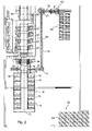
- Fig. 1 is a printing system with a device for transporting rolls of material 01 shown in a schematic view from above.
- the packaged material rolls 01 are transported by means of a suitable means of transport, for example a nip stacker, into the region of an unpacking station 03 and stored there on a roll former 04.
- the material rolls 01 are manually rolled onto a first transport carriage 27.
- the first transport carriage 27 has for this purpose at the top of a suitable trough, which is suitable for the secure storage of the rolls of material 01.
- the roll of material 01 is transported to the middle of the unpacking station 03, positioned centrally and then unpacked manually.
- the necessary splices 15 are also attached to the web start of the roll of material 01 by the operator so that the Auspackstation 03 also serves as a splice preparation station 03 at the same time.
- the web-processing machine 06 is designed in the manner of a web-fed rotary printing press 06, in which four printing couples 07 are consecutively traversed by a printing material web.
- the printing substrate can be printed, for example, four-color and two-sided and is then dried in a dryer 08.
- the web-processing machine 06 is preceded by a reel changer 09, in which two material rolls 01 can be clamped. With the roll changer 09 a flying roll change can be realized without machine downtime.
- the web-fed rotary printing press is gravure printing or
- Offset printing machine eg commercial web press
- z. Hall floor, bearings and / or roll changers and / or printing units e.g. arranged one behind the other in a plane 20 (based on the web running direction).
- a bearing 11 is provided, which is designed as an intermediate storage for storing the daily requirement of rolls of material 01.
- a first transport carriage 27 can be parked with a material roll 01 mounted thereon.
- a second trolley 27 After preparing the splices 15 on the roll of material 01 takes on the Auspackstation 03 in the raised state of the Materialrolle01, a second trolley 27, the roll of material 01 and travels with this to the transfer position to the trolley 32. There, the trolley 27 is piggybacked on the trolley 32 , By moving the second transport carriage 32, the splice-prepared material roll 01 can optionally be conveyed via a transport path 14 directly to the roll changer 09 or via the transport path 12 into the bearing 11. The decision as to whether the material roll 01 is conveyed from the unpacking station 03 directly to the reel changer 09 or into the bearing 11 falls under the control of a material supply system.
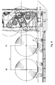
- the second transport carriage 32 with the first transport carriage 27 charged thereon and the material roll 01 loaded thereon travel via the transport path 12 into the storage 11 until an empty storage space 13 is reached.
- the first trolley 27 can be inserted into the branch path 16 of the storage bin 13.
- the second trolley 32 leaves the bearing 11 again via the transport path 12, optionally also another first trolley 27 from the Camp 11 can be taken.
- the bearing 11 is protected against unauthorized entry. On three sides of the bearing 11, the protection of a secured area, in particular a fencing formed. On the side facing the reel changer 09 of the bearing 11, a lock 18 is provided in the area safeguard 37 of the reel changer 09. In the area of the lock 18, the area protection 37 by light barriers or sensors, for. B. laser sensors that operate without contact implemented.
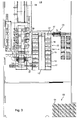
- a second system variant is shown schematically.
- This variant is different from the one in Fig. 1 illustrated variant in that between the unpacking 03 and the reel changer 09 and the bearing 11, an additional transport path 19 is provided, via which the second trolley 32 the piggyback loaded first trolley 27 and the material roll 01 mounted thereon to the reel changer 09 and the camp 11 transported.
- transport path 19 two turntables 21 are installed to the direction changes of the first transport carriage 27th between the unpacking 03 and the bearing 11 and the reel changer 09 to realize.
- a transport path 23 extends through the bearing 22 and thereby runs at right angles to the web running direction of the web-processing machine 06.
- the first trolley 27 along the transport path 23 passes through the entire camp 22.
- splice prepared material roll 01 either temporarily stored in the warehouse 22 or directly promoted to reel changer 09.
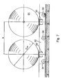
- the storage bins 13 of the bearing 22 are located on both sides of the transport path 12, and thus parallel to the web-processing machine 06, resulting in a very compact system configuration.
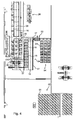
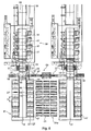
- Fig. 4 is presented a fourth variation, which is largely the in Fig. 3 corresponds to the system shown. Unlike the in Fig. 3 However, in the case of the bearing 24, only storage bins 13 are provided on the left side of the transport path 12, so that an overall even more compact system configuration is made possible. The control of the system via a control station 26th
- first transport carriages 27 are used for transporting and removing new or expired material rolls 01.
- first transport carriages 27 are, for example, rail-guided.
- the trolley 27 has four rollers 28 which roll on rails.
- To drive the trolley 27 may be provided, for example, a running under floor drag conveyor, the z. B. is designed as a circulating chain. With this necklace is the Dolly 27 connected at least temporarily.
- On a frame of the trolley 27, a trough-like shell 29 is mounted for receiving the rolls of material 01. This serving as a receptacle shell 29 protrudes from the bottom 31 of the storage room, while the first transport carriage 27 extends sunk below the bottom 31 of the storage room.
- each track sections are provided, in which the first transport carts 27 can enter with their rollers 28.
- a separate chain drive is provided in each storage place 13 to a separate chain drive.
- at least the majority of storage bins 13 have separate chain drives.
- the storage bins 13 or stitch cords 16 each receive a roll of material 01 or a transport carriage 27. But these can also record exactly 2 or more rolls of material 01.
- each second transport carriage 32 For conveying the first transport carriage 27 along the transport paths 12 and 14 are second transport carts 32.
- the frame of each second transport carriage 32 has a short track section 33, in each of which a first transport carriage 27 can enter with its rollers 28.
- the second trolleys 32 are also arranged below the floor and provided with four guided on rails rollers 34. To drive the second trolleys 32 also chain conveyor can be used.
- the second trolley 32 may in an alternative embodiment, two track sections 33; 33 'had.
- a distance a of the two track sections 33; 33 ' is greater than a maximum diameter D max of the material rolls 01 to be transported.
- the distance a of the two track sections 33; 33 'of the trolley 32 equal to the distance a of the track sections 33; 33 'of the stitch cords 16 of the storage bins 13.
- At least one of the transport carriage 27 may carry an adapter for receiving residual roles.
- the longitudinal direction and web running direction of the web-processing machine are substantially in the same direction.
- At least one printing unit 07, the reel changer 09 and the storage bins 13 are arranged approximately in a common plane 20. An arrangement of all printing units 07 in a common plane 20 is advantageous.
- the processing machine furthermore has a single reel changer.
- the transport path of the second transport carriage 32 and the longitudinal axis 10 of a dryer 08 of the processing machine are arranged so that they lie in alignment, or are arranged to extend parallel offset.
- the reference point is used in the printing units 07 and the reel changer 09, the lower edge of the respective side frame and, at the storage bins 13 receiving the transport carriage 27.
- the common plane 20 is the building floor.
- the device for transporting material rolls works taking into account the specific roll data recorded in the transport or preparation process, such as, for example, Barcode and / or roll width and / or roll status and / or weights (gross, net weight 1, net weight 2) and / or gluing time and / or run length, etc.
- the data is maintained and managed in the respective process steps.
- the evaluation and storage for further exploitation of this data via a suitable management system. It is also possible to make use of the role data acquired during and after the unwinding process via the reel splicer (s) for transfer to the specific data record of the reel and its allocation.
- the device is suitable to act in the transport, preparation and data management processes partial or mulchen of the production process and to manage accordingly.
- An expression of this are the with the transports of sub-roles z. B. associated with adapters operations. Also, for example, the management of the adapter (with and without roles) and all necessary operations for this purpose can be integrated.
- Another characteristic feature of such a device is the use of multiple trolleys per storage position and all operations required for this purpose.
- a variant is also the use of a transfer table with several rail tracks, which allows further optimizations of said device.
- Another possible expression is the transport of the sleeve container and its data content to certain, for example, freely selectable positions in the warehouse or to transport other possible positions in said device. Also included here can be other data transfers to the management system or to further evaluation units of the machine or the production preparation.
Landscapes
- Replacement Of Web Rolls (AREA)
- Warehouses Or Storage Devices (AREA)
- Winding, Rewinding, Material Storage Devices (AREA)
Abstract
Description
Die Erfindung betrifft eine Vorrichtung zum Transport von Materialrollen gemäß dem Oberbegriff des Anspruchs 1.The invention relates to a device for transporting material rolls according to the preamble of
An bahnverarbeitenden Maschinen, beispielsweise Rollenrotationsdruckmaschinen, sind sogenannte Rollenwechsler vorhanden, die der Materialversorgung der Maschine, beispielsweise mit einer Druckstoffbahn, dienen. Bei einem Rollenwechsel wird die abgelaufene Materialrolle aus dem Rollenwechsler entnommen und durch eine neue Materialrolle ersetzt. Zum Transport der neuen Materialrollen zum Rollenwechsler bzw. zum Abtransport der abgelaufenen Materialrollen vom Rollenwechsler sind verschiedene Transportsysteme aus dem Stand der Technik bekannt.On web-processing machines, such as web-fed rotary printing presses, there are so-called roll changers which serve to supply the material to the machine, for example with a printing material web. When a roll change the expired roll of material is removed from the roll changer and replaced by a new roll of material. Various transport systems from the prior art are known for transporting the new rolls of material to the roll changer or for removing the expired rolls of material from the roll changer.
In der
Die
Die
Die
Die
Die
Die
Der Erfindung liegt die Aufgabe zugrunde, eine Vorrichtung zum Transport von Materialrollen zu schaffen.The invention has for its object to provide a device for transporting rolls of material.
Die Aufgabe wird erfindungsgemäß durch die Merkmale des Anspruchs 1 gelöst.The object is achieved by the features of
Ein Vorteil der erfindungsgemäßen Vorrichtung liegt insbesondere darin, dass der zweite Transportwagen auf zumindest einem Transportweg auch in ein Lager verfahrbar ist, in dem auf mehreren Lagerplätzen neue und/oder vollständig bzw. teilweise abgelaufene Materialrollen gelagert werden können. Der vorhandene zweite Transportwagen zur Aufachsung der Materialrollen im Rollenwechsler kann auf diese Weise auch zum Transport der Materialrollen aus einem Lager bzw. in ein Lager hinein genutzt werden. Außerdem ist es denkbar, dass der zweite Transportwagen neue Materialrollen entweder direkt zum Rollenwechsler fördert oder die neuen Materialrollen zunächst im Lager abgestellt und bis zum Abruf für eine spätere Verwendung zwischengelagert werden. Insbesondere kann durch die neue Vorrichtung ein umständliches Umladen zwischen den einzelnen Abschnitten für verschiedene zweite Transportwagen vermieden werden.An advantage of the device according to the invention is, in particular, that the second transport carriage can be moved on at least one transport path into a warehouse in which new and / or completely or partially expired material rolls can be stored on several storage locations. The existing second trolley for Aufachsung the rolls of material in the roll changer can be used in this way also for transporting the material rolls from a warehouse or in a warehouse inside. In addition, it is conceivable that the second trolley promotes new material rolls either directly to the reel changer or the new material rolls are first placed in the warehouse and stored until retrieval for later use. In particular, a cumbersome reloading between the individual sections for different second transport vehicles can be avoided by the new device.
Nach einer bevorzugten Ausführungsform ist das Lager als Zwischenlager, insbesondere in der Art eines Tageslagers, ausgebildet. D. h. das Lager, das mit dem zweitenAccording to a preferred embodiment, the bearing is designed as an intermediate storage, in particular in the manner of a daily storage. Ie. the camp, that with the second
Transportwagen anfahrbar ist, dient nicht zur Lagerung des gesamten Bestandes an Materialrollen, sondern ist lediglich zur Zwischenlagerung eines bestimmten, vorzugsweise kleineren Anteils an Materialrollen in der Nähe des Rollenwechslers vorgesehen. Die Materialrollen im Zwischenlager sollten dabei vorzugsweise bereits ausgepackt und für den Rollenwechsel mit Klebestellen vorbereitet sein. Ist das Lager in der Art eines Tageslagers ausgebildet, werden im Tageslager ungefähr soviel Materialrollen zwischengelagert, wie für den Tagesbedarf der bahnverarbeitenden Maschine ungefähr erforderlich sind.Transport carriage is approachable, not used for storage of the entire inventory of rolls of material, but is only intended for temporary storage of a certain, preferably smaller proportion of rolls of material in the vicinity of the roll changer. The rolls of material in the intermediate storage should preferably already be unpacked and prepared for the roll change with splices. If the bearing is designed in the manner of a daily storage, about as many material rolls are temporarily stored in the day store as are approximately necessary for the daily requirements of the web-processing machine.
Prinzipiell ist es denkbar, dass die Materialrollen in den Lagerplätzen des Lagers wiederum vom ersten Transportwagen abgeladen werden. Dadurch können jedoch Beschädigungen an den Materialrollen auftreten. Die Lagerplätze im Lager sollten deshalb vorzugsweise derart ausgebildet sein, dass in jedem Lagerplatz zumindest ein erster Transportwagen anordenbar ist. Es können auch unbeladene erste Transportwagen an den verschiedenen Lagerplätzen abgestellt werden, um dadurch einen relativ maschinennahen Lagerplatz für die ersten Transportwagen zu schaffen.In principle, it is conceivable that the rolls of material in the storage bins of the warehouse are in turn unloaded by the first transport carriage. As a result, however, damage to the rolls of material can occur. The storage bins in the warehouse should therefore preferably be designed such that at least one first transport carriage can be arranged in each storage bin. It can also be unladen first trolley parked at the various storage bins, thereby creating a relatively close to the machine storage space for the first dolly.
Bei der Anordnung der Transportwagen in den verschiedenen Lagerplätzen des Lagers sollte vorzugweise Wahlfreiheit bestehen, so dass im Ergebnis letztendlich jeder erste Transportwagen an jedem Lagerplatz des Lagers abstellbar ist. Dadurch wird eine sehr große Flexibilität und Variabilität bei der Nutzung des Lagers realisiert.In the arrangement of the trolley in the different storage bins of the camp should preferably freedom of choice exist, so that ultimately every first dolly at each storage space of the camp is turned off. As a result, a very large flexibility and variability in the use of the warehouse is realized.
Der Funktionsumfang zur Nutzung des zweiten Transportwagens kann erheblich dadurch gesteigert werden, dass der erste Transportwagen auf einem Transportweg auch in eine Auspackstation zum Auspacken der Materialrolle verfahrbar ist. Auf diese Weise können neue Materialrollen nach dem Auspacken in der Auspackstation abgeholt und zu nachgeordneten Bearbeitungsstationen transportiert werden.The range of functions for using the second trolley can be significantly increased by the fact that the first trolley on a transport path in a unpacking for unpacking the roll of material is movable. In this way, new material rolls can be picked up after unpacking in the unpacking and transported to downstream processing stations.
Weiterhin ist es besonders vorteilhaft, wenn der erste Transportwagen auf einemFurthermore, it is particularly advantageous if the first dolly on a
Transportweg auch in eine Klebestellenvorbereitungsstation verfahrbar ist. Auf diese Weise könne die ausgepackten Materialrollen nach der Anbringung der Klebestellen am Bahnanfang aus der Klebestellenvorbereitungsstation abgeholt und zu nachgeordneten Bearbeitungsstationen weitertransportiert werden. Dabei sind insbesondere auch Anlagekonfigurationen denkbar, bei denen die Klebestellenvorbereitungsstation zugleich als Auspackstation dient, so dass der erste Transportwagen die Materialrollen aus dieser Kombistation abholt und zu nachgeordneten Bearbeitungsstationen weitertransportiert.Transport path can also be moved in a splice preparation station. In this way, the unpacked rolls of material can be picked up after the attachment of the splices at the beginning of the web from the splice preparation station and transported to downstream processing stations. In particular, system configurations are also conceivable in which the splice preparation station also serves as an unpacking station, so that the first transport carriage picks up the material rolls from this combination station and transports them to downstream processing stations.
Im Sinne eines rationellen Materialtransports sollte die Auspackstation und/oder die Klebestellenvorbereitungsstation bezogen auf die Transportrichtung der Materialrollen den Lagerplätzen im Lager vorgeordnet sein. Auf diese Weise werden beim Transport von ausgepackten bzw. Klebestellen vorbereiteten Materialrollen in das Lager nur sehr kurze Transportwege benötigt. Die ausgepackten bzw. klebestellenvorbereiteten Materialrollen können dann später mittels des zweiten Transportwagens aus dem Lager abgeholt und zum Rollenwechsler weitertransportiert werden.For the purposes of rational material transport, the unpacking station and / or the splice preparation station should be arranged upstream of the storage locations in the warehouse with respect to the transport direction of the material rolls. In this way, only very short transport routes are required in the transport of unwrapped or splices prepared material roles in the camp. The unpacked or splice-prepared rolls of material can then be retrieved from the warehouse later by means of the second trolley and transported on to the roll changer.
Um möglichst wenig Richtungswechsel beim Transport der Materialrollen zum Rollenwechsler erforderlich zu machen, ist es besonders vorteilhaft, wenn der Transportweg im Lager, auf dem der zweite Transportwagen verfahrbar ist, sich in virtueller Verlängerung der Bahnlaufrichtung der bahnverarbeitenden Maschine erstreckt.In order to make as little change of direction when transporting the material rolls required for reel changer, it is particularly advantageous if the transport in the camp on which the second trolley is movable, extending in virtual extension of the web running direction of the web-processing machine.
Alternativ bzw. additiv dazu kann sich der Transportweg im Lager auch parallel zur Verlängerung der Bahnlaufrichtung der bahnverarbeitenden Maschine erstrecken, wodurch insbesondere sehr kompakte Anlagenkonfigurationen realisierbar sind.Alternatively or in addition thereto, the transport path in the bearing can also extend parallel to the extension of the web running direction of the web-processing machine, whereby in particular very compact system configurations can be realized.
In welcher Weise die Lagerplätze im Lager konfiguriert werden, ist grundsätzlich beliebig. Nach einer bevorzugten Ausführungsform erstrecken sich vom Transportweg im Lager Stichstränge, über die die Lagerplätze angefahren werden können. Dadurch ist es beispielsweise denkbar, dass der zweite Transportwagen den huckepack beladenen ersten Transportwagen bis zum Stichstrang transportiert und dort der erste Transportwagen durch Einfahren in den Stichstrang die Materialrolle an den entsprechenden Lagerplatz ablagert. Auf diese Weise bleibt der erste Transportwagen zusammen mit der entsprechenden Materialrolle an dem Lagerplatz, bis die Materialrolle wieder von dem Lagerplatz abgerufen und durch Aufladen des ersten Transportwagens auf den zweiten Transportwagen weitertransportiert wird.The way in which the storage bins are configured in the warehouse is basically arbitrary. According to a preferred embodiment, the transport path in the bearing extends through the strands through which the storage bins can be approached. This makes it conceivable, for example, that the second trolley loaded piggyback transported first transport trolley to the stitch line and there the first trolley deposits by moving into the stitch line the roll of material to the appropriate storage space. In this way, the first trolley remains with the appropriate roll of material at the storage place until the roll of material is retrieved again from the storage space and transported by charging the first trolley on the second trolley.
Je nach Anlagenkonfiguration können Lagerplätze auf beiden Seiten des Transportweges oder nur auf einer Seite des Transportweges vorgesehen sein.Depending on the system configuration, storage bins may be provided on both sides of the transport path or only on one side of the transport path.
Für die Funktion der Vorrichtung ist eine möglichst exakte Positionierung des zweiten Transportwagens von großer Bedeutung. Soll beispielsweise der zweite Transportwagen beim Abladen eines ersten Transportwagens vor einem Stichstrang positioniert werden, ist die exakte Positionierung unerlässlich, da ansonsten der erste Transportwagen nicht in den Stichstrang eingefahren werden kann. Es sollte deshalb entlang zumindest bestimmter Abschnitte des Transportweges ein Wegmesssystem vorgesehen sein, mit dem der zweite Transportwagen exakt positioniert werden kann.For the function of the device as exact as possible positioning of the second trolley is of great importance. If, for example, the second transport trolley is to be positioned in front of a stub line when unloading a first transport trolley, the exact positioning is essential, since otherwise the first transport trolley can not be run into the stub line. It should therefore be provided along at least certain sections of the transport path a Wegmesssystem with which the second trolley can be accurately positioned.
Für die Betriebssicherheit sollte weiterhin eine Bereichsabsicherung vorgesehen sein, durch die die Grenzen des Lagers gegen unbefugtes Betreten abgesichert werden.For operational safety, area coverage should continue to be provided to protect the boundaries of the warehouse against unauthorized entry.
Auf besonders einfache Weise kann die Bereichsabsicherung durch Anbringung einer Umzäunung an den Grenzen des Lagers ausgebildet sein. Durch Nutzung der Bereichsabsicherung am Rollenwechsler als gleichzeitige Bereichsabsicherung des Lagers kann der Aufwand zur Realisation der Bereichsabsicherung abgesenkt werden.In a particularly simple manner, the area security can be formed by attaching a fence at the boundaries of the camp. By using the area security on the reel changer as simultaneous area security of the warehouse, the effort for realizing the area security can be reduced.
Zum Ein- bzw. Ausfördern von Materialrollen in das Lager kann eine Schleuse in der Bereichsabsicherung vorgesehen sein. Im Schleusenbereich sollte die Bereichsabsicherung vorzugsweise berührungslos arbeiten, beispielsweise durch Einsatz von Lichtschranken oder Ultraschallsensoren. Durch Anordnung der Sensoren in unterschiedlichen Höhen können komplexe Abfrageroutinen realisiert werden, so dass beispielsweise Materialrollen problemlos die Schleuse passieren können, wohingegen durch ein unbefugtes Übersteigen der Sensorsignale ein Alarm ausgelöst wird.For introducing or removing material rolls into the bearing, a lock may be provided in the area protection. In the lock area, the area protection should preferably work non-contact, for example by use of light barriers or ultrasonic sensors. By arranging the sensors at different heights, complex interrogation routines can be realized, so that, for example, material rolls can easily pass through the sheath, whereas an alarm is triggered by an unauthorized exceeding of the sensor signals.
Um zu vermeiden, dass Materialrollen im Lager zu lange gelagert werden, sollte das Lager nach dem FIFO-Prinzip (first in, first out) betrieben werden. Dies bedeutet, dass Materialrollen die zuerst dem Lager zugeführt wurden, auch als erstes an den Rollenwechsler weitertransportiert werden.To prevent material rolls in the warehouse from being stored too long, the warehouse should be operated according to the FIFO principle (first in, first out). This means that material rolls that were first fed to the warehouse are also first transported to the roll changer.
Ausführungsbeispiele der Erfindung sind in den Zeichnungen dargestellt und werden im Folgenden näher beschrieben.Embodiments of the invention are illustrated in the drawings and will be described in more detail below.
Es zeigen:
- Fig. 1
- eine erste Variante einer Druckanlage mit einer Vorrichtung zum Transport von Materialrollen;
- Fig. 2
- eine zweite Variante einer Druckanlage mit einer Vorrichtung zum Transport von Materialrollen;
- Fig. 3
- eine dritte Variante einer Druckanlage mit einer Vorrichtung zum Transport von Materialrolle;
- Fig. 4
- eine vierte Variante einer Druckanlage mit einer Vorrichtung zum Transport von Materialrollen;
- Fig. 5
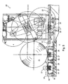
- den Rollenwechsler der Druckanlagen gemäß
Fig. 1 bis Fig. 4 im Querschnitt; - Fig. 6
- die Vorrichtung zum Transport von Materialrollen mit einem Transportwagen in verschieden Positionen;
- Fig. 7
- eine Variante des Transportwagens zur Aufnahme von zwei Materialrollen;
- Fig. 8
- eine weitere Variante einer Druckanlage mit zwei Tageslagern.
- Fig. 1
- a first variant of a printing system with a device for transporting rolls of material;
- Fig. 2
- a second variant of a printing system with a device for transporting rolls of material;
- Fig. 3
- a third variant of a printing system with a device for transporting roll of material;
- Fig. 4
- a fourth variant of a printing system with a device for transporting rolls of material;
- Fig. 5
- according to the roll changer of the printing systems
Fig. 1 to Fig. 4 in cross-section; - Fig. 6
- the device for transporting rolls of material with a trolley in different positions;
- Fig. 7
- a variant of the trolley for receiving two rolls of material;
- Fig. 8
- Another variant of a printing system with two day warehouses.
In
Die bahnverarbeitende Maschine 06 ist in der Art einer Rollenrotationsdruckanlage 06 ausgebildet, in der vier Druckwerke 07 hintereinander von einer Bedruckstoffbahn durchlaufen werden. Die Bedruckstoffbahn kann dabei beispielsweise vierfarbig und beidseitig bedruckt werden und wird anschließend in einem Trockner 08 getrocknet. Zur Versorgung der Druckwerke 07 mit der Bedruckstoffbahn ist der bahnverarbeitenden Maschine 06 ein Rollenwechsler 09 vorgeordnet, in dem zwei Materialrollen 01 aufgespannt werden können. Mit dem Rollenwechsler 09 kann ein fliegender Rollenwechsel ohne Maschinenstillstand realisiert werden.The web-processing
Insbesondere ist die Rollenrotationsdruckmaschine als Tiefdruck- oderIn particular, the web-fed rotary printing press is gravure printing or
Offsetdruckmaschine (z. B. Akzidenzdruckmaschine) ausgebildet. Vorzugsweise sind z. B. Hallenboden, Lager und/oder Rollenwechsler und/oder Druckwerke z.B. hintereinander in einer Ebene 20 (bezogen auf die Bahnlaufrichtung) angeordnet.Offset printing machine (eg commercial web press) is formed. Preferably z. Hall floor, bearings and / or roll changers and / or printing units e.g. arranged one behind the other in a plane 20 (based on the web running direction).
In unmittelbarer Nähe des Rollenwechslers 09 ist ein Lager 11 vorgesehen, das als Zwischenlager zur Lagerung des Tagesbedarfs an Materialrollen 01 ausgebildet ist. Beidseitig eines Transportweges 12 sind jeweils acht Lagerplätze 13 im Lager 11 vorgesehen. In jedem Lagerplatz 13 kann ein erster Transportwagen 27 mit einer darauf gelagerten Materialrolle 01 abgestellt werden.In the immediate vicinity of the
Nach dem Vorbereiten der Klebestellen 15 an der Materialrolle 01 übernimmt an der Auspackstation 03 im angehobenen Zustand der Materialrolle01, ein zweiter Transportwagen 27 die Materialrolle 01 und fährt mit dieser zur Übergabeposition an den Transportwagen 32. Dort wird der Transportwagen 27 huckepack auf den Transportwagen 32 aufgeladen. Durch Verfahren des zweiten Transportwagens 32 kann die klebestellenvorbereitete Materialrolle 01 wahlweise über einen Transportwege 14 direkt zum Rollenwechsler 09 oder über den Transportweg 12 ins Lager 11 gefördert werden. Die Entscheidung darüber, ob die Materialrolle 01 von der Auspackstation 03 direkt zum Rollenwechsler 09 oder ins Lager 11 gefördert wird, fällt die Steuerung eines Materialversorgungssystems.After preparing the
Soll die klebestellenvorbereitete Materialrolle 01 ins Lager 11 gefördert werden, so fährt der zweite Transportwagen 32 mit dem darauf huckepack aufgeladenen ersten Transportwagen 27 und der darauf aufgeladenen Materialrolle 01 über den Transportweg 12 ins Lager 11 ein bis ein leerer Lagerplatz 13 erreicht ist. Vor dem leeren Lagerplatz 13 wird der zweite Transportwagen 32 dann derart positioniert, dass der erste Transportwagen 27 in den Stichweg 16 des Lagerplatzes 13 eingeschoben werden kann. Anschließend verlässt der zweite Transportwagen 32 das Lager 11 wieder über den Transportweg 12, wobei wahlweise auch ein anderer erster Transportwagen 27 aus dem Lager 11 mitgenommen werden kann. Sobald am Rollenwechsler 09 eine neue Materialrolle 01 angefordert wird, wird entweder eine soeben ausgepackte Materialrolle 01 aus der Auspackstation 03 über den Transportweg 14 zum Rollenwechsler 09 gefördert oder eine bereits mit Klebestellen 15 versehene Materialrolle 01 aus dem Lager 11 zum Rollenwechsler 09 gefördert.If the splice-
Da sich der Transportweg 12 durch das Lager 11 in virtueller Verlängerung der Bahnlaufrichtung durch die bahnverarbeitende Maschine 06 erstreckt, ist bei Transport einer Materialrolle 01 aus dem Lager 11 zum Rollenwechsler 09 kein Richtungswechsel des zweiten Transportwagens 32 erforderlich.Since the
Das Lager 11 ist gegen unbefugtes Betreten geschützt. An drei Seiten des Lagers 11 wird die Absicherung von einem abgesicherten Bereich, insbesondere einer Umzäunung, gebildet. An der zum Rollenwechsler 09 gerichteten Seite des Lagers 11 ist eine Schleuse 18 in der Bereichsabsicherung 37 des Rollenwechslers 09 vorgesehen. Im Bereich der Schleuse 18 wird die Bereichsabsicherung 37 durch Lichtschranken oder Sensoren, z. B. Lasersensoren, die berührungslos arbeiten, realisiert.The
Beim Ein- bzw. Auslagern der Materialrollen 01 ins Lager 11 wird nach dem FIFO-Prinzip gearbeitet, um zu verhindern, dass die Materialrollen 01 zu lang im Lager 11 zwischengelagert werden, wodurch die Klebestellen 15 unbrauchbar werden.When loading or unloading the rolls of
In
Bei der in
In
In
In den Stichsträngen 16 sind jeweils Gleisabschnitte vorgesehen, in die die ersten Transportwägen 27 mit ihren Laufrollen 28 einfahren können. In jedem Lagerplatz 13 ist dazu ein separater Kettenantrieb vorgesehen. Vorzugsweise weisen zumindest die Mehrzahl der Lagerplätze 13 separate Kettenantriebe auf.In the stitch strings 16 each track sections are provided, in which the
Die Lagerplätze 13 bzw. Stichstränge 16 nehmen jeweils eine Materialrolle 01 bzw. einen Transportwagen 27 auf. Auch können diese aber auch genau 2 oder mehr Materialrollen 01 aufnehmen.The
Zur Förderung der ersten Transportwagen 27 entlang der Transportwege 12 und 14 dienen zweite Transportwägen 32. Das Gestell jedes zweiten Transportwagens 32 weist einen kurzen Gleisabschnitt 33 auf, in den jeweils ein erster Transportwagen 27 mit seinen Laufrollen 28 einfahren kann. Die zweiten Transportwägen 32 sind ebenfalls unter Flur angeordnet und mit vier auf Schienen geführten Laufrollen 34 versehen. Zum Antrieb der zweiten Transportwägen 32 können ebenfalls Kettenförderer eingesetzt werden.For conveying the
Der zweite Transportwagen 32 kann in einer alternativen Ausführung auch zwei Gleisabschnitte 33; 33' aufwiesen. Ein Abstand a der beiden Gleisabschnitte 33; 33' ist dabei größer als ein maximaler Durchmesser Dmax der zu transportierenden Materialrollen 01. Vorzugsweise ist der Abstand a der beiden Gleisabschnitte 33; 33' des Transportwagens 32 gleich dem Abstand a der Gleisabschnitte 33; 33' der Stichstränge 16 der Lagerplätze 13.The
Mindestens einer der Transportwagen 27 kann einen Adapter zur Aufnahme von Restrollen tragen.At least one of the
Die Längsrichtung und Bahnlaufrichtung der bahnverarbeitenden Maschine verlaufen im wesentlichen in der gleichen Richtung.The longitudinal direction and web running direction of the web-processing machine are substantially in the same direction.
Zwischen den Lagerplätzen 13 und dem Rollenwechsler 09 sind keine Drehscheiben für die Transportwägen 27 angeordnet. Ebenso sind keine Drehscheiben zwischen den Lagerplätzen 13 und der Klebevorbereitungsstation 03 für die Transportwägen 27 angeordnet.Between the
Mindestens ein Druckwerk 07, der Rollenwechsler 09 und die Lagerplätze 13 sind annähernd in einer gemeinsamen Ebene 20 angeordnet. Vorteilhaft ist eine Anordnung aller Druckwerke 07 in einer gemeinsamen Ebene 20. Die Bearbeitungsmaschine weist weiterhin einen einzigen Rollenwechsler auf. Der Transportweg des zweiten Transportwagens 32 und die Längsachse 10 eines Trockners 08 der Bearbeitungsmaschine sind so angeordnet, dass sie in einer Flucht liegen, bzw. parallel versetzt verlaufend angeordnet sind.At least one
Als Bezugspunkt dient dabei bei den Druckwerken 07 und den Rollenwechsler 09 die Unterkante des jeweiligen Seitengestell und, bei den Lagerplätzen 13 die Aufnahme der Transportwagen 27. Die gemeinsame Ebene 20 ist dabei der Gebäudeboden.The reference point is used in the
Die Vorrichtung zum Transport von Materialrollen arbeitet unter Berücksichtigung der spezifischen, im Transport- bzw. Vorbereitungsprozess erfassten Rollendaten, wie z. B. Barcode und/oder Rollenbreite und/oder Rollenstatus und/oder Gewichte (Brutto-, Nettogewicht 1, Nettogewicht 2) und/oder Klebezeit und/oder Lauflänge usw.. Dies umfasst beispielsweise die Datenerfassung und/oder Datenpflege und/oder Datenzuordnung im Gesamtprozess, d. h. vom Wareneingang bis zur Hülsenentsorgung. Somit werden die Daten in den jeweiligen Prozessschritten gehalten und verwaltet. Verbunden hiermit kann beispielsweise auch die Auswertung und Abspeicherung zur weiteren Verwertung dieser Daten über ein geeignetes Verwaltungssystem sein. Weiter besteht die Möglichkeit, unter Nutzung der über den/die Rollenwechsler während und nach dem Abwickelprozess erfassten Rollendaten zur Übernahme in den spezifischen Datensatz der Rolle und deren Zuordnung vorzunehmen.The device for transporting material rolls works taking into account the specific roll data recorded in the transport or preparation process, such as, for example, Barcode and / or roll width and / or roll status and / or weights (gross,
Weiterhin ist die Vorrichtung geeignet, sowohl in den Transport-, Vorbereitungs- und Datenverwaltungsprozessen Teil- bzw. Rücklieferrollen vom Produktionsprozess zu handeln und entsprechend zu verwalten. Dies schließt sämtliche damit verbundene Prozesse ein. Eine Ausprägung hiervon sind die mit den Transporten von Teilrollen z. B. mit Adaptern verbundenen Vorgängen. Ebenfalls integriert werden können beispielsweise auch die Verwaltung der Adapter (mit und ohne Rollen) und sämtliche hierfür erforderlichen Vorgänge.Furthermore, the device is suitable to act in the transport, preparation and data management processes partial or Rücklieferrollen of the production process and to manage accordingly. This includes all related processes. An expression of this are the with the transports of sub-roles z. B. associated with adapters operations. Also, for example, the management of the adapter (with and without roles) and all necessary operations for this purpose can be integrated.
Ein weiteres Ausprägungsmerkmal einer derartigen Vorrichtung entsteht bei der Verwendung von mehreren Rollwägen pro Lagerposition und sämtliche hierzu erforderlichen Vorgängen.Another characteristic feature of such a device is the use of multiple trolleys per storage position and all operations required for this purpose.
Eine Variante ist ebenfalls die Verwendung eines Transfertisches mit mehreren Schienensträngen, welche weitere Optimierungen der genannten Vorrichtung ermöglicht.A variant is also the use of a transfer table with several rail tracks, which allows further optimizations of said device.
Weitere mögliche Ausprägung ist der Transport des Hülsenbehälters und dessen Dateninhaltes auf bestimmte, beispielsweise frei wählbare Positionen im Lager bzw. zu weiteren möglichen Positionen in der genannten Vorrichtung zu transportieren. Beinhaltet können hier ebenfalls weitere Datenübergaben zum Verwaltungssystem bzw. zu weiteren Auswerte-Einheiten der Maschine bzw. der Produktionsvorbereitung sein.Another possible expression is the transport of the sleeve container and its data content to certain, for example, freely selectable positions in the warehouse or to transport other possible positions in said device. Also included here can be other data transfers to the management system or to further evaluation units of the machine or the production preparation.
- 0101
- Materialrollematerial roll
- 0202
- Hauptlagermain bearing
- 0303
- Auspackstation, KlebestellenvorbereitungsstationUnpacking station, splice preparation station
- 0404
- Rollenvorlagerole template
- 0505
- --
- 0606
- bahnverarbeitende Maschine, Bearbeitungsmaschine, Rollenrotationsdruckanlage, Rollenrotationsdruckmaschineweb-processing machine, processing machine, web-fed rotary printing press, web-fed rotary printing machine
- 0707
- Druckwerk, BahnbearbeitungsstationPrinting unit, web processing station
- 0808
- Trocknerdryer
- 0909
- Rollenwechslerreelstands
- 1010
- Längsachselongitudinal axis
- 1111
- Lager, TageslagerWarehouse, day camp
- 11'11 '
- Gleisabschnitttrack section
- 1212
- Transportwegtransport
- 1313
- Lagerplatzcampsite
- 1414
- Transportwegtransport
- 1515
- Klebestellensplices
- 1616
- Stichstrang, StichwegStingstring, Stichweg
- 1717
- abgesicherter Bereichsecured area
- 1818
- Schleuselock
- 1919
- Transportwegtransport
- 2020
- Ebenelevel
- 2121
- Drehscheibeturntable
- 2222
- Lager, TageslagerWarehouse, day camp
- 2323
- Transportwegtransport
- 2424
- Lager, TageslagerWarehouse, day camp
- 2525
- --
- 2626
- Leitstandcontrol station
- 2727
- Transportwagen, ersterDolly, first
- 2828
- Laufrollecaster
- 2929
- SchaleBowl
- 3030
- --
- 3131
- Bodenground
- 3232
- Transportwagen, zweiterDolly, second
- 3333
- Gleisabschnitttrack section
- 33'33 '
- Gleisabschnitttrack section
- 3434
- Laufrollecaster
- 3535
- --
- 3636
- ÜbergabepositionTransfer position
- 3737
- Bereichsabsicherung, abgesicherter BereichArea protection, secured area
- aa
- Abstand der Gleisabschnitte bzw. der StichsträngeDistance of the track sections or the stitch cords
- Dmax D max
- Maximaler Durchmesser einer zu transportierenden MaterialrolleMaximum diameter of a material roll to be transported
Claims (78)
- Apparatus for transporting material reels (01), the material reels (01) being arranged on a first transport carriage (27) and the said transport carriage (27) being arranged on a second transport carriage (32), the second transport carriage (32) moving between a store (11; 22; 24) having a plurality of store places (13) and a reel changer (09) of a web-processing machine (06), the second transport carriage (32) moving with the first transport carriage (27) and the material reel (01) which is mounted on it until an on-axis and/or unloading position of the reel changer (09), characterized in that at least two of the store places (13) which are arranged directly behind one another in the longitudinal direction of the web-processing machine (06) and/or spur lines (16) which belong to the store places (13) are at a spacing (a) which is dimensioned in such a way that two new material reels (01) can be stored or are stored.
- Apparatus according to Claim 1, characterized in that the material reels (01) are stored on first transport carriages (27) in the store places (13).
- Apparatus according to Claim 1, characterized in that, in relation to the transport direction of the material reels (01), the store places (13) are arranged behind a preparation station (03) for the manual or machine application of adhesive elements.
- Apparatus according to Claim 1, characterized in that each time a plurality of store places (13) for material reels (01) are arranged on both sides of the transport path (12).
- Apparatus according to Claim 1, characterized in that the store (11; 22; 24) is configured in the manner of a buffer store, in particular in the manner of a daily store.
- Apparatus according to Claim 1, characterized in that at least two material reels (01) which have already been unpacked and prepared with adhesive points (15) for the reel change are stored in the store places (13) of the store (11; 22; 24).
- Apparatus according to Claim 6, characterized in that all the new material reels (01) are prepared with adhesive points (15).
- Apparatus according to Claim 1, characterized in that the first transport carriages (27) can optionally be parked in each store place (13) of the store (11; 22; 24).
- Apparatus according to Claim 1 or 2, characterized in that at least one first transport carriage (27) can also be moved on a transport path (19) into an unpacking station (03) for unpacking the material reels (01).
- Apparatus according to Claim 9, characterized in that at least one first transport carriage (27) can also be moved on a transport path (19) into an adhesive-point preparation station (03) for preparing the adhesive points (15) on the material reel (01).
- Apparatus according to Claim 10, characterized in that the adhesive-point preparation station (03) can be used at the same time as an unpacking station (03).
- Apparatus according to Claim 1, characterized in that, in a virtual extension of the web running direction of the web-processing machine (06), a transport path (12) is provided in the store (11), on which transport path (12) the second transport carriage (32) can be moved.
- Apparatus according to Claim 1, characterized in that a transport path (12), on which the second transport carriage (32) can be moved, is provided in the store (11) parallel to the extension of the web running direction of the web-processing machine (06).
- Apparatus according to Claim 1, characterized in that the store places (13) can be approached via spur lines (16) which extend, in particular, at right angles from the transport path (11).
- Apparatus according to Claim 1, characterized in that store places (13) are provided only on one side of a transport path (12).
- Apparatus according to Claim 1, characterized in that a distance measuring system for the exact positioning of the second transport carriage (32) is provided along at least certain sections of a transport path (12).
- Apparatus according to Claim 1, characterized in that the store (11; 22; 24) is secured against unauthorized access by a secured region (17; 37) which is placed at the boundaries of the store (11; 22; 24).
- Apparatus according to Claim 17, characterized in that the secured region (17) of the store (11, 24) is formed in sections by a boundary fence.
- Apparatus according to Claim 17 or 18, characterized in that the secured region (17) of the store (11) is formed in sections by the region securing means (37) of the reel changer (09).
- Apparatus according to one of Claims 17, 18 or 19, characterized in that at least one lock (18) for introducing and/or discharging material reels (01) is provided in the region securing means (37).
- Apparatus according to Claim 20, characterized in that the store (11) is secured against unauthorized access in the region of the lock (18) by light barriers or ultrasound sensors.
- Apparatus according to Claim 21, characterized in that there are a plurality of light barriers or ultrasound sensors which are arranged at different heights.
- Apparatus according to one of Claims 1 to 22, characterized in that a plurality of processing stations (07) are provided behind one another in the longitudinal direction in the web-processing machine (06).
- Apparatus according to one of Claims 1 to 23, characterized in that at least one processing station (07) is configured as a printing unit (07) of a web-fed printing press (06) in the web-processing machine (06).
- Apparatus according to Claim 24, characterized in that the web-fed printing press (06) has a horizontal web course through the printing units (07).
- Apparatus according to Claim 1, characterized in that the store (11; 22; 24) is configured as a FIFO store.
- Apparatus according to Claim 1, characterized in that a control desk is provided for operating the web-processing machine and the store (11; 22; 24) is arranged next to the control desk.
- Apparatus according to Claim 1, characterized in that the first transport carriage (27) has running rollers (28) and runs on rails.
- Apparatus according to Claim 1, characterized in that the second transport carriage (32) has running rollers (34) and runs on rails.
- Apparatus according to Claim 29, characterized in that a frame of the second transport carriage (32) has a short rail section (33), into which the first transport carriage (27) runs.
- Apparatus according to Claim 28 or 29, characterized in that the drive of the transport carriages (27; 32) takes place by chain conveyors.
- Apparatus according to Claim 30, characterized in that the second transport carriage (32) has two rail sections (33; 33') which are arranged at a spacing (a).
- Apparatus according to Claim 32, characterized in that the spacing (a) of the two rail sections (33; 33') is greater than a maximum diameter (Dmax) of a material reel (01) to be transported.
- Apparatus according to Claim 1, characterized in that at least part of the store places (13) and/or spur lines (16) which belong to the store places (13) receive a single transport carriage (27).
- Apparatus according to Claim 1, characterized in that the majority of the store places (13) and/or spur lines (16) which belong to the store places (13) receive a single transport carriage (27).
- Apparatus according to Claim 1, characterized in that all the store places (13) and/or spur lines (16) which belong to the store places (13) receive a single transport carriage (27).
- Apparatus according to Claim 36, characterized in that at least part of the store places (13) and/or spur lines (16) which belong to the store places (13) receive two transport carriages (27).
- Apparatus according to Claim 37, characterized in that the majority of the store places (13) and/or spur lines (16) which belong to the store places (13) receive two transport carriages (27).
- Apparatus according to Claim 38, characterized in that all the store places (13) and/or spur lines (16) which belong to the store places (13) receive two transport carriages (27).
- Apparatus according to Claim 39, characterized in that at least part of the store places (13) and/or spur lines (16) which belong to the store places (13) receive more than two transport carriages (27).
- Apparatus according to Claim 40, characterized in that the majority of the store places (13) and/or spur lines (16) which belong to the store places (13) receive more than two transport carriages (27).
- Apparatus according to Claim 41, characterized in that all the store places (13) and/or spur lines (16) which belong to the store places (13) receive more than two transport carriages (27).
- Apparatus according to Claim 1 or 2, characterized in that at least one transport carriage (27) carries an adapter for receiving a part reel.
- Apparatus according to Claim 1, characterized in that two stores (11; 11') are arranged with in each case one second transport carriage (32).
- Apparatus according to Claim 44, characterized in that the transport paths (14) of the two transport carriages (32) are arranged so as to extend in parallel.
- Apparatus according to Claim 44, characterized in that the two stores (11; 11') are connected by means of a rail.
- Apparatus according to Claim 44, characterized in that an adhesive-point preparation station (03) is arranged between the two stores (11; 11').
- Apparatus according to Claim 1, 3 or 44, characterized in that the second transport carriage (32) is arranged so as to transport the adhesively prepared material reels (01) into the store (11; 11').
- Apparatus according to Claim 1, characterized in that at least two of the store places (13) which are arranged directly behind one another in the longitudinal direction of the web-processing machine (06) and/or spur lines (16) which belong to the store places (13) are at a spacing (a) which is greater than a maximum diameter (Dmax) of the material reel (01) to be transported.
- Apparatus according to Claim 1, characterized in that the majority of the store places (13) which are arranged directly behind one another in the longitudinal direction of the web-processing machine and/or spur lines (16) which belong to the store places (13) are at a spacing (a) which is greater than a maximum diameter (Dmax) of the material reel (01) to be transported.
- Apparatus according to Claim 1, characterized in that the majority of the store places (13) which are arranged directly behind one another in the longitudinal direction of the web-processing machine (06) and/or spur lines (16) which belong to the store places (13) are at a spacing (a) which is dimensioned in such a way that two new material reels (01) can be stored or are stored.
- Apparatus according to Claim 1, characterized in that all the store places (13) which are arranged directly behind one another in the longitudinal direction of the web-processing machine (06) and/or spur lines (16) which belong to the store places (13) are at a spacing (a) which is greater than a maximum diameter (Dmax) of the material reel (01) to be transported.
- Apparatus according to Claim 1, characterized in that all the store places (13) which are arranged directly behind one another in the longitudinal direction of the web-processing machine (06) and/or spur lines (16) which belong to the store places (13) are at a spacing (a) which is dimensioned in such a way that two new material reels (01) can be stored or are stored.
- Apparatus according to Claim 4, characterized in that at least three store places (13) for material reels (01) are arranged each time on both sides of the transport path (12).
- Apparatus according to Claim 1, characterized in that new material reels (01) can be stored or are stored in at least two of the store places (13) which are arranged directly behind one another in the longitudinal direction of the web-processing machine (06).
- Apparatus according to Claim 1, characterized in that new material reels (01) can be stored or are stored in the majority of the store places (13) which are arranged directly behind one another in the longitudinal direction of the web-processing machine (06).
- Apparatus according to Claim 1, characterized in that new material reels (01) can be stored or are stored in all the store places (13) which are arranged directly behind one another in the longitudinal direction of the web-processing machine (06).
- Apparatus according to Claim 1, characterized in that material reels (01) with a maximum diameter (Dmax) can be stored in at least two of the store places (13) which are arranged directly behind one another in the longitudinal direction of the web-processing machine (06).
- Apparatus according to Claim 1, characterized in that material reels (01) with a maximum diameter (Dmax) can be stored in the majority of the store places (13) which are arranged directly behind one another in the longitudinal direction of the web-processing machine (06).
- Apparatus according to Claim 1, characterized in that material reels (01) with a maximum diameter (Dmax) can be stored in all the store places (13) which are arranged directly behind one another in the longitudinal direction of the web-processing machine (06).
- Apparatus according to Claim 51, 53 or 55 to 57, characterized in that the new material reels (01) are provided with adhesives (15).
- Apparatus according to Claim 23, characterized in that the longitudinal direction and web running direction of the web-processing machine (06) extend substantially in the same direction.
- Apparatus according to Claim 1, characterized in that no turntable for the transport carriages (27) is arranged between the store places (13) and the reel changer (09).
- Apparatus according to Claim 3, characterized in that no turntable for the transport carriages (27) is arranged between the store places (13) and the adhesive preparation station (03).
- Apparatus according to Claim 24, characterized in that at least one printing unit (07), the reel changer (09) and the store places (13) are arranged approximately in a common plane (20).
- Apparatus according to Claim 65, characterized in that all the printing units (07) are arranged in a common plane (20).
- Apparatus according to Claim 1, characterized in that the web-running machine (06) has a single reel changer (09).
- Apparatus according to Claim 1 or 3, characterized in that the transport path (12) of the second transport carriage (32) and the longitudinal axis (10) of a dryer (08) of the web-processing machine (06) lie in alignment.
- Apparatus according to Claim 1 or 3, characterized in that the transport path (12) of the second transport carriage (32) and the longitudinal axis (10) of a dryer (08) of the web-processing machine (06) are arranged so as to extend offset in parallel.
- Apparatus according to Claim 1, characterized in that, in the majority of the store places (13), each store place (13) has a dedicated drive for transporting the material reels (01).
- Apparatus according to Claim 1 or 2, characterized in that, in the majority of the store places (13), each store place (13) is assigned in each case a dedicated underfloor conveying system for the transport carriages (27).
- Apparatus according to Claim 71, characterized in that the underfloor conveying system has a circulating driving means.
- Apparatus according to Claim 72, characterized in that the driving means is configured as a chain.
- Apparatus according to Claim 1 or 2, characterized in that each first transport carriage (27) has a dedicated drive.
- Apparatus according to Claim 70, characterized in that all the store places (13) have a dedicated drive.
- Apparatus according to Claim 71, characterized in that all the store places (13) have in each case a dedicated underfloor conveying system.
- Apparatus according to Claim 1, characterized in that the second transport carriage (32) has a dedicated drive.
- Apparatus according to Claim 77, characterized in that the drive of the second transport carriage (32) can be actuated independently of the drives of the first transport carriages (27).
Priority Applications (2)
| Application Number | Priority Date | Filing Date | Title |
|---|---|---|---|
| EP07104342A EP1801057A1 (en) | 2004-02-23 | 2005-02-09 | Device for transporting reels of material |
| EP09168172A EP2113478A1 (en) | 2004-02-23 | 2005-02-09 | Device for transporting reels of material |
Applications Claiming Priority (3)
| Application Number | Priority Date | Filing Date | Title |
|---|---|---|---|
| DE102004008771 | 2004-02-23 | ||
| DE102004021605A DE102004021605B4 (en) | 2004-02-23 | 2004-05-03 | Device for transporting rolls of material |
| PCT/EP2005/050569 WO2005080241A2 (en) | 2004-02-23 | 2005-02-09 | Devices for transporting reels of material |
Related Child Applications (4)
| Application Number | Title | Priority Date | Filing Date |
|---|---|---|---|
| EP07104342A Division EP1801057A1 (en) | 2004-02-23 | 2005-02-09 | Device for transporting reels of material |
| EP09168172A Division EP2113478A1 (en) | 2004-02-23 | 2005-02-09 | Device for transporting reels of material |
| EP07104342.6 Division-Into | 2007-03-16 | ||
| EP09168172.6 Division-Into | 2009-08-19 |
Publications (2)
| Publication Number | Publication Date |
|---|---|
| EP1718552A2 EP1718552A2 (en) | 2006-11-08 |
| EP1718552B1 true EP1718552B1 (en) | 2011-02-02 |
Family
ID=34888809
Family Applications (1)
| Application Number | Title | Priority Date | Filing Date |
|---|---|---|---|
| EP05716652A Expired - Lifetime EP1718552B1 (en) | 2004-02-23 | 2005-02-09 | Device for transporting reels of material |
Country Status (5)
| Country | Link |
|---|---|
| US (1) | US8011871B2 (en) |
| EP (1) | EP1718552B1 (en) |
| JP (1) | JP2007533565A (en) |
| BR (1) | BRPI0507951A (en) |
| WO (1) | WO2005080241A2 (en) |
Families Citing this family (20)
| Publication number | Priority date | Publication date | Assignee | Title |
|---|---|---|---|---|
| DE102006008104A1 (en) * | 2006-02-20 | 2007-10-18 | Koenig & Bauer Aktiengesellschaft | Device for covering a danger zone on a reel changer and a method for controlling a device |
| DE102006019595B3 (en) * | 2006-04-27 | 2007-12-13 | Koenig & Bauer Aktiengesellschaft | Safety device for making dangerous areas safe on a reel- changer has tread matting in a dangerous area for a swiveling range of a reel-arm on a reel-changer |
| DE102006048675B3 (en) * | 2006-10-14 | 2007-12-27 | Koenig & Bauer Aktiengesellschaft | Temporary storage facility for e.g. rotary printing press, has transportation lift with trolley that receives roll feeding devices in piggyback manner and is movable on guide rails of intermediate storage facility positions |
| DE102007025800B4 (en) | 2007-06-02 | 2013-10-17 | Koenig & Bauer Aktiengesellschaft | Dangerous area protection for the area of automatic roll loading on a roll changer |
| DE102007028683A1 (en) * | 2007-06-21 | 2008-12-24 | Maschinenfabrik Wifag | Roller changing device with trolley system |
| DE102008042813A1 (en) * | 2008-10-14 | 2010-04-22 | Koenig & Bauer Aktiengesellschaft | Dangerous area protection for the area of automatic roll loading on a roll changer |
| DE102009046069A1 (en) * | 2009-10-28 | 2011-05-12 | Manroland Ag | Conveyor system for a rotary printing machine |
| PL2335910T3 (en) * | 2009-12-18 | 2018-09-28 | Lm Wind Power International Technology Ii Aps | Loading apparatus and method of loading rolls of fibre based sheet material to an application unit |
| DE102010001014A1 (en) | 2010-01-19 | 2011-09-08 | Koenig & Bauer Aktiengesellschaft | Reel changer with protection of a security area |
| CN102858666B (en) | 2010-04-28 | 2015-11-25 | 柯尼格及包尔公开股份有限公司 | Roll changer with safety device and method for using the roll changer with safety device |
| DE102010031650A1 (en) | 2010-07-22 | 2012-01-26 | Koenig & Bauer Aktiengesellschaft | Roll changer for use in roller-rotary printing machine, has protection cover partially closing off opening of safety zone from safety area, where opening extends parallel to rotation axis of retaining device for retaining material rolls |
| DE102010028289B4 (en) | 2010-04-28 | 2013-11-28 | Koenig & Bauer Aktiengesellschaft | Reel changer with safety device |
| EP2563701B1 (en) | 2010-04-28 | 2016-06-29 | Koenig & Bauer AG | Roll changer having a safety device and method for using a roll changer having a safety device |
| DE102010028292B4 (en) | 2010-04-28 | 2013-09-05 | Koenig & Bauer Aktiengesellschaft | Method for correcting alignment of a first roll relative to a roll changer and a roll changer with guard |
| FI126344B (en) * | 2012-05-22 | 2016-10-14 | Upm Raflatac Oy | Method and apparatus for handling narrow rollers |
| DE102012211708B4 (en) | 2012-07-05 | 2015-07-09 | Koenig & Bauer Aktiengesellschaft | Roll supply system of a web-fed printing press, web-fed printing press and method for operating a web-fed reel feeding system |
| JP5926403B2 (en) * | 2012-12-25 | 2016-05-25 | 平田機工株式会社 | Transport system |
| DE102013226022B4 (en) * | 2013-12-16 | 2017-06-14 | Koenig & Bauer Ag | Method for conveying a printing substrate, processing unit of a printing material supply system and printing material supply system |
| DE102017211828A1 (en) * | 2017-07-11 | 2019-01-17 | Koenig & Bauer Ag | Printing machine with a roll unwinder and method of handling rolls of sheet material |
| KR102658024B1 (en) * | 2021-05-07 | 2024-04-15 | 삼성에스디에스 주식회사 | Cylindrical material storing device and method thereof |
Family Cites Families (22)
| Publication number | Priority date | Publication date | Assignee | Title |
|---|---|---|---|---|
| DE2944265A1 (en) * | 1979-11-02 | 1982-03-25 | Jagenberg-Werke AG, 4000 Düsseldorf | DEVICE FOR THE MULTIPLE ROLLING OF RAILWAYS |
| US4537368A (en) * | 1984-05-01 | 1985-08-27 | Carborundum Abrasives Company | Pendulum roll loader |
| JPH0768000B2 (en) | 1985-12-28 | 1995-07-26 | 大日本印刷株式会社 | Paper feeder of printing machine |
| FI80862C (en) * | 1986-11-18 | 1990-08-10 | Kone Oy | Apparatus for handling paper rolls in a plant, such as printing |
| JPH0786058B2 (en) | 1987-03-28 | 1995-09-20 | 大日本印刷株式会社 | Conveying device to the paper feed section of the printing machine |
| DE3910444C3 (en) * | 1989-03-31 | 1998-10-22 | Wifag Maschf | Automatic system for feeding paper rolls into the roll stands of a web-fed rotary printing press |
| US5076751A (en) * | 1990-03-23 | 1991-12-31 | Jervis B. Webb Company | Reelroom newsprint roll handling apparatus and method |
| JPH04197903A (en) * | 1990-11-28 | 1992-07-17 | Mitsubishi Heavy Ind Ltd | Automatic reel delivery method |
| DE29516155U1 (en) | 1995-10-11 | 1995-12-07 | Hörmann Logistik GmbH, 80992 München | Shelving system |
| DE29519942U1 (en) | 1995-12-18 | 1996-04-25 | Bruckbauer, Siegfried, 93138 Lappersdorf | High-bay warehouse and security shutters for such a high-bay warehouse |
| DE19637771C2 (en) * | 1996-09-16 | 2002-01-24 | Koenig & Bauer Ag | Dolly |
| DE19637772A1 (en) * | 1996-09-16 | 1998-03-26 | Koenig & Bauer Albert Ag | Procedure for transporting rolls to a roll changer |
| DE19637770A1 (en) * | 1996-09-16 | 1998-03-19 | Koenig & Bauer Albert Ag | Process and system for the automatic feeding and removal of rolls |
| DE59706549D1 (en) * | 1996-12-21 | 2002-04-11 | Koenig & Bauer Ag | Method for registering and positioning a supply web roll |
| DE10035788C1 (en) * | 2000-07-22 | 2002-03-14 | Koenig & Bauer Ag | Method and device for controlling web tension in a rotary printing press |
| DE10150810B4 (en) * | 2001-10-15 | 2011-01-13 | Wifag Maschinenfabrik Ag | Reel changer and method for removing a residual roll |
| GB2382340B (en) | 2001-11-26 | 2003-11-19 | Sca Hygiene Prod Gmbh | Method and transportation device for transporting a product from a remote place to a converting machine |
| EP1329397A1 (en) | 2002-01-18 | 2003-07-23 | Westfalia WST Systemtechnik GmbH & Co. KG | Transport device |
| DE10213459A1 (en) | 2002-03-26 | 2003-10-30 | Koenig & Bauer Ag | Goods transport system with a rail network and a method for operating this goods transport system |
| US6948901B2 (en) * | 2002-11-12 | 2005-09-27 | Metso Paper Ag | Paper roll storage and handling installation and method for storing and handling paper rolls |
| DE20307581U1 (en) | 2003-05-15 | 2003-09-25 | Voith Paper Patent GmbH, 89522 Heidenheim | Machine with traction drum winding paper onto core, moves carriage supporting core into change-over position when replacement is necessary |
| ATE385981T1 (en) * | 2004-07-02 | 2008-03-15 | Metso Paper Ag | SYSTEM FOR FEEDING PAPER ROLLS TO A ROLL STAND AND METHOD FOR OPERATING SAME |
-
2005
- 2005-02-09 WO PCT/EP2005/050569 patent/WO2005080241A2/en not_active Ceased
- 2005-02-09 BR BRPI0507951-9A patent/BRPI0507951A/en not_active IP Right Cessation
- 2005-02-09 JP JP2006523022A patent/JP2007533565A/en active Pending
- 2005-02-09 US US10/590,390 patent/US8011871B2/en not_active Expired - Fee Related
- 2005-02-09 EP EP05716652A patent/EP1718552B1/en not_active Expired - Lifetime
Also Published As
| Publication number | Publication date |
|---|---|
| BRPI0507951A (en) | 2007-07-24 |
| WO2005080241A3 (en) | 2006-02-02 |
| JP2007533565A (en) | 2007-11-22 |
| EP1718552A2 (en) | 2006-11-08 |
| US20070170298A1 (en) | 2007-07-26 |
| US8011871B2 (en) | 2011-09-06 |
| WO2005080241A2 (en) | 2005-09-01 |
Similar Documents
| Publication | Publication Date | Title |
|---|---|---|
| EP1718552B1 (en) | Device for transporting reels of material | |
| EP0925246B2 (en) | Method for transporting rolls to a roll changer | |
| EP0925247B2 (en) | Haulage car for paper rolls | |
| EP0261508B1 (en) | Device for transporting paper rolls to packaging machines | |
| EP0925248B1 (en) | Installation for loading and unloading rolls automatically | |
| WO2013004695A1 (en) | System and method for placing a storage good into a rack and removing a storage good from a rack | |
| DE102017205133A1 (en) | Method and device for removing a web roll from a roll carrier of a web-processing machine | |
| DE19606554C1 (en) | Mobile self-driven vehicle for transporting cylindrical rolls, especially paper | |
| EP1892207A2 (en) | Device for distribution and/or sorting of rolls of material and their transfer and a method for transporting rolls of material | |
| EP1586522B1 (en) | Method of operating a conveying system | |
| EP1801057A1 (en) | Device for transporting reels of material | |
| EP1632447B9 (en) | Store control device and system for the preparation and intermediate storage of paper reels and feeding thereof to at least one reel stand and method for its operation. | |
| EP1733980B1 (en) | Device for transporting of at least a roll of material | |
| DE4416213A1 (en) | Installation for storage and insertion of paper reels into web=fed printing press | |
| EP1612169B1 (en) | Installation for feeding paper reels to a reel stand and method for its operation | |
| DE102016218108B4 (en) | Method and device for removing a printed in a web-fed printing press and the output side of the web press on a rewinder wound product roll | |
| DE602004006202T2 (en) | Method and device for handling loads | |
| DE102017206036B4 (en) | Method for operating a web winder, web winder and machine with such a web winder | |
| DE102016218107B4 (en) | Device for monitoring the state of charge of a movable on a transport path of a roller transport system transport | |
| DE19611494A1 (en) | Decoiling system for coil roller | |
| DE102016218106B4 (en) | Method and device for removing a web roll from a roll carrier of a web-processing machine | |
| EP1491476A2 (en) | Transport installation for feeding paper rolls to rollstands and method for operation | |
| EP1491475A1 (en) | Transport installation for feeding paper rolls to roll stands and bobbin carriage | |
| DE102008029965A1 (en) | Roller changing arrangement for a web-fed printing machine comprises a roller feeding system configured so that at least two of the roller changers are charged with paper rolls via transport carriages running on a common delivery path | |
| DE102021116550A1 (en) | Device and method for transporting rolls |
Legal Events
| Date | Code | Title | Description |
|---|---|---|---|
| PUAI | Public reference made under article 153(3) epc to a published international application that has entered the european phase |
Free format text: ORIGINAL CODE: 0009012 |
|
| 17P | Request for examination filed |
Effective date: 20060331 |
|
| AK | Designated contracting states |
Kind code of ref document: A2 Designated state(s): AT BE BG CH CY CZ DE DK EE ES FI FR GB GR HU IE IS IT LI LT LU MC NL PL PT RO SE SI SK TR |
|
| 17Q | First examination report despatched |
Effective date: 20070308 |
|
| DAX | Request for extension of the european patent (deleted) | ||
| GRAP | Despatch of communication of intention to grant a patent |
Free format text: ORIGINAL CODE: EPIDOSNIGR1 |
|
| GRAS | Grant fee paid |
Free format text: ORIGINAL CODE: EPIDOSNIGR3 |
|
| GRAA | (expected) grant |
Free format text: ORIGINAL CODE: 0009210 |
|
| RTI1 | Title (correction) |
Free format text: DEVICE FOR TRANSPORTING REELS OF MATERIAL |
|
| AK | Designated contracting states |
Kind code of ref document: B1 Designated state(s): AT BE BG CH CY CZ DE DK EE ES FI FR GB GR HU IE IS IT LI LT LU MC NL PL PT RO SE SI SK TR |
|
| REG | Reference to a national code |
Ref country code: GB Ref legal event code: FG4D Free format text: NOT ENGLISH |
|
| REG | Reference to a national code |
Ref country code: CH Ref legal event code: EP |
|
| REG | Reference to a national code |
Ref country code: IE Ref legal event code: FG4D Free format text: LANGUAGE OF EP DOCUMENT: GERMAN |
|
| REF | Corresponds to: |
Ref document number: 502005010931 Country of ref document: DE Date of ref document: 20110317 Kind code of ref document: P |
|
| REG | Reference to a national code |
Ref country code: DE Ref legal event code: R096 Ref document number: 502005010931 Country of ref document: DE Effective date: 20110317 |
|
| REG | Reference to a national code |
Ref country code: ES Ref legal event code: FG2A Ref document number: 2356742 Country of ref document: ES Kind code of ref document: T3 Effective date: 20110412 |
|
| REG | Reference to a national code |
Ref country code: NL Ref legal event code: VDEP Effective date: 20110202 |
|
| LTIE | Lt: invalidation of european patent or patent extension |
Effective date: 20110202 |
|
| PG25 | Lapsed in a contracting state [announced via postgrant information from national office to epo] |
Ref country code: GR Free format text: LAPSE BECAUSE OF FAILURE TO SUBMIT A TRANSLATION OF THE DESCRIPTION OR TO PAY THE FEE WITHIN THE PRESCRIBED TIME-LIMIT Effective date: 20110503 Ref country code: PT Free format text: LAPSE BECAUSE OF FAILURE TO SUBMIT A TRANSLATION OF THE DESCRIPTION OR TO PAY THE FEE WITHIN THE PRESCRIBED TIME-LIMIT Effective date: 20110602 Ref country code: SE Free format text: LAPSE BECAUSE OF FAILURE TO SUBMIT A TRANSLATION OF THE DESCRIPTION OR TO PAY THE FEE WITHIN THE PRESCRIBED TIME-LIMIT Effective date: 20110202 Ref country code: LT Free format text: LAPSE BECAUSE OF FAILURE TO SUBMIT A TRANSLATION OF THE DESCRIPTION OR TO PAY THE FEE WITHIN THE PRESCRIBED TIME-LIMIT Effective date: 20110202 |
|
| BERE | Be: lapsed |
Owner name: KOENIG & BAUER A.G. Effective date: 20110228 |
|
| PG25 | Lapsed in a contracting state [announced via postgrant information from national office to epo] |
Ref country code: PL Free format text: LAPSE BECAUSE OF FAILURE TO SUBMIT A TRANSLATION OF THE DESCRIPTION OR TO PAY THE FEE WITHIN THE PRESCRIBED TIME-LIMIT Effective date: 20110202 Ref country code: SI Free format text: LAPSE BECAUSE OF FAILURE TO SUBMIT A TRANSLATION OF THE DESCRIPTION OR TO PAY THE FEE WITHIN THE PRESCRIBED TIME-LIMIT Effective date: 20110202 Ref country code: FI Free format text: LAPSE BECAUSE OF FAILURE TO SUBMIT A TRANSLATION OF THE DESCRIPTION OR TO PAY THE FEE WITHIN THE PRESCRIBED TIME-LIMIT Effective date: 20110202 Ref country code: BG Free format text: LAPSE BECAUSE OF FAILURE TO SUBMIT A TRANSLATION OF THE DESCRIPTION OR TO PAY THE FEE WITHIN THE PRESCRIBED TIME-LIMIT Effective date: 20110502 Ref country code: NL Free format text: LAPSE BECAUSE OF FAILURE TO SUBMIT A TRANSLATION OF THE DESCRIPTION OR TO PAY THE FEE WITHIN THE PRESCRIBED TIME-LIMIT Effective date: 20110202 Ref country code: CY Free format text: LAPSE BECAUSE OF FAILURE TO SUBMIT A TRANSLATION OF THE DESCRIPTION OR TO PAY THE FEE WITHIN THE PRESCRIBED TIME-LIMIT Effective date: 20110202 |
|
| REG | Reference to a national code |
Ref country code: IE Ref legal event code: FD4D |
|
| PG25 | Lapsed in a contracting state [announced via postgrant information from national office to epo] |
Ref country code: MC Free format text: LAPSE BECAUSE OF NON-PAYMENT OF DUE FEES Effective date: 20110228 |
|
| PLBI | Opposition filed |
Free format text: ORIGINAL CODE: 0009260 |
|
| PG25 | Lapsed in a contracting state [announced via postgrant information from national office to epo] |
Ref country code: IE Free format text: LAPSE BECAUSE OF FAILURE TO SUBMIT A TRANSLATION OF THE DESCRIPTION OR TO PAY THE FEE WITHIN THE PRESCRIBED TIME-LIMIT Effective date: 20110202 Ref country code: DK Free format text: LAPSE BECAUSE OF FAILURE TO SUBMIT A TRANSLATION OF THE DESCRIPTION OR TO PAY THE FEE WITHIN THE PRESCRIBED TIME-LIMIT Effective date: 20110202 Ref country code: EE Free format text: LAPSE BECAUSE OF FAILURE TO SUBMIT A TRANSLATION OF THE DESCRIPTION OR TO PAY THE FEE WITHIN THE PRESCRIBED TIME-LIMIT Effective date: 20110202 |
|
| 26 | Opposition filed |
Opponent name: MANROLAND AG Effective date: 20111025 |
|
| PG25 | Lapsed in a contracting state [announced via postgrant information from national office to epo] |
Ref country code: BE Free format text: LAPSE BECAUSE OF NON-PAYMENT OF DUE FEES Effective date: 20110228 Ref country code: CZ Free format text: LAPSE BECAUSE OF FAILURE TO SUBMIT A TRANSLATION OF THE DESCRIPTION OR TO PAY THE FEE WITHIN THE PRESCRIBED TIME-LIMIT Effective date: 20110202 Ref country code: RO Free format text: LAPSE BECAUSE OF FAILURE TO SUBMIT A TRANSLATION OF THE DESCRIPTION OR TO PAY THE FEE WITHIN THE PRESCRIBED TIME-LIMIT Effective date: 20110202 Ref country code: SK Free format text: LAPSE BECAUSE OF FAILURE TO SUBMIT A TRANSLATION OF THE DESCRIPTION OR TO PAY THE FEE WITHIN THE PRESCRIBED TIME-LIMIT Effective date: 20110202 |
|
| PLAX | Notice of opposition and request to file observation + time limit sent |
Free format text: ORIGINAL CODE: EPIDOSNOBS2 |
|
| REG | Reference to a national code |
Ref country code: DE Ref legal event code: R026 Ref document number: 502005010931 Country of ref document: DE Effective date: 20111025 |
|
| PLBB | Reply of patent proprietor to notice(s) of opposition received |
Free format text: ORIGINAL CODE: EPIDOSNOBS3 |
|
| PGFP | Annual fee paid to national office [announced via postgrant information from national office to epo] |
Ref country code: CH Payment date: 20120227 Year of fee payment: 8 |
|
| PGFP | Annual fee paid to national office [announced via postgrant information from national office to epo] |
Ref country code: IT Payment date: 20120222 Year of fee payment: 8 |
|
| PLAB | Opposition data, opponent's data or that of the opponent's representative modified |
Free format text: ORIGINAL CODE: 0009299OPPO |
|
| R26 | Opposition filed (corrected) |
Opponent name: MANROLAND WEB SYSTEMS GMBH Effective date: 20111025 |
|
| PGFP | Annual fee paid to national office [announced via postgrant information from national office to epo] |
Ref country code: AT Payment date: 20120220 Year of fee payment: 8 |
|
| PGFP | Annual fee paid to national office [announced via postgrant information from national office to epo] |
Ref country code: FR Payment date: 20130314 Year of fee payment: 9 Ref country code: GB Payment date: 20130221 Year of fee payment: 9 Ref country code: DE Payment date: 20130322 Year of fee payment: 9 |
|
| PG25 | Lapsed in a contracting state [announced via postgrant information from national office to epo] |
Ref country code: LU Free format text: LAPSE BECAUSE OF NON-PAYMENT OF DUE FEES Effective date: 20110209 |
|
| PGFP | Annual fee paid to national office [announced via postgrant information from national office to epo] |
Ref country code: ES Payment date: 20120213 Year of fee payment: 8 |
|
| PLAB | Opposition data, opponent's data or that of the opponent's representative modified |
Free format text: ORIGINAL CODE: 0009299OPPO |
|
| PG25 | Lapsed in a contracting state [announced via postgrant information from national office to epo] |
Ref country code: IS Free format text: LAPSE BECAUSE OF FAILURE TO SUBMIT A TRANSLATION OF THE DESCRIPTION OR TO PAY THE FEE WITHIN THE PRESCRIBED TIME-LIMIT Effective date: 20110202 |
|
| R26 | Opposition filed (corrected) |
Opponent name: MANROLAND AG Effective date: 20111025 |
|
| PG25 | Lapsed in a contracting state [announced via postgrant information from national office to epo] |
Ref country code: TR Free format text: LAPSE BECAUSE OF FAILURE TO SUBMIT A TRANSLATION OF THE DESCRIPTION OR TO PAY THE FEE WITHIN THE PRESCRIBED TIME-LIMIT Effective date: 20110202 |
|
| REG | Reference to a national code |
Ref country code: CH Ref legal event code: PL |
|
| PLBP | Opposition withdrawn |
Free format text: ORIGINAL CODE: 0009264 |
|
| REG | Reference to a national code |
Ref country code: AT Ref legal event code: MM01 Ref document number: 497472 Country of ref document: AT Kind code of ref document: T Effective date: 20130228 |
|
| PLBD | Termination of opposition procedure: decision despatched |
Free format text: ORIGINAL CODE: EPIDOSNOPC1 |
|
| PG25 | Lapsed in a contracting state [announced via postgrant information from national office to epo] |
Ref country code: LI Free format text: LAPSE BECAUSE OF NON-PAYMENT OF DUE FEES Effective date: 20130228 Ref country code: AT Free format text: LAPSE BECAUSE OF NON-PAYMENT OF DUE FEES Effective date: 20130228 Ref country code: CH Free format text: LAPSE BECAUSE OF NON-PAYMENT OF DUE FEES Effective date: 20130228 Ref country code: HU Free format text: LAPSE BECAUSE OF FAILURE TO SUBMIT A TRANSLATION OF THE DESCRIPTION OR TO PAY THE FEE WITHIN THE PRESCRIBED TIME-LIMIT Effective date: 20110202 |
|
| PG25 | Lapsed in a contracting state [announced via postgrant information from national office to epo] |
Ref country code: IT Free format text: LAPSE BECAUSE OF NON-PAYMENT OF DUE FEES Effective date: 20130209 |
|
| PLBM | Termination of opposition procedure: date of legal effect published |
Free format text: ORIGINAL CODE: 0009276 |
|
| STAA | Information on the status of an ep patent application or granted ep patent |
Free format text: STATUS: OPPOSITION PROCEDURE CLOSED |
|
| 27C | Opposition proceedings terminated |
Effective date: 20131108 |
|
| REG | Reference to a national code |
Ref country code: ES Ref legal event code: FD2A Effective date: 20140409 |
|
| PG25 | Lapsed in a contracting state [announced via postgrant information from national office to epo] |
Ref country code: ES Free format text: LAPSE BECAUSE OF NON-PAYMENT OF DUE FEES Effective date: 20130210 |
|
| REG | Reference to a national code |
Ref country code: DE Ref legal event code: R119 Ref document number: 502005010931 Country of ref document: DE |
|
| GBPC | Gb: european patent ceased through non-payment of renewal fee |
Effective date: 20140209 |
|
| REG | Reference to a national code |
Ref country code: FR Ref legal event code: ST Effective date: 20141031 |
|
| REG | Reference to a national code |
Ref country code: DE Ref legal event code: R119 Ref document number: 502005010931 Country of ref document: DE Effective date: 20140902 |
|
| PG25 | Lapsed in a contracting state [announced via postgrant information from national office to epo] |
Ref country code: DE Free format text: LAPSE BECAUSE OF NON-PAYMENT OF DUE FEES Effective date: 20140902 Ref country code: FR Free format text: LAPSE BECAUSE OF NON-PAYMENT OF DUE FEES Effective date: 20140228 Ref country code: GB Free format text: LAPSE BECAUSE OF NON-PAYMENT OF DUE FEES Effective date: 20140209 |