EP1708910B1 - Scheibenwischeranlage für fahrzeuge, insbesondere strassenfahrzeuge - Google Patents
Scheibenwischeranlage für fahrzeuge, insbesondere strassenfahrzeuge Download PDFInfo
- Publication number
- EP1708910B1 EP1708910B1 EP05701138A EP05701138A EP1708910B1 EP 1708910 B1 EP1708910 B1 EP 1708910B1 EP 05701138 A EP05701138 A EP 05701138A EP 05701138 A EP05701138 A EP 05701138A EP 1708910 B1 EP1708910 B1 EP 1708910B1
- Authority
- EP
- European Patent Office
- Prior art keywords
- wiper
- wiper blade
- articulation
- arm
- windscreen
- Prior art date
- Legal status (The legal status is an assumption and is not a legal conclusion. Google has not performed a legal analysis and makes no representation as to the accuracy of the status listed.)
- Expired - Lifetime
Links
- 230000008878 coupling Effects 0.000 description 13
- 238000010168 coupling process Methods 0.000 description 13
- 238000005859 coupling reaction Methods 0.000 description 13
- 239000000463 material Substances 0.000 description 2
- 230000007246 mechanism Effects 0.000 description 2
- 238000000034 method Methods 0.000 description 2
- 230000008569 process Effects 0.000 description 2
- 230000009467 reduction Effects 0.000 description 2
- 229910000639 Spring steel Inorganic materials 0.000 description 1
- 238000005452 bending Methods 0.000 description 1
- 230000001419 dependent effect Effects 0.000 description 1
- 238000011161 development Methods 0.000 description 1
- 230000018109 developmental process Effects 0.000 description 1
- 239000011521 glass Substances 0.000 description 1
- 238000009434 installation Methods 0.000 description 1
- 238000012423 maintenance Methods 0.000 description 1
- 238000004080 punching Methods 0.000 description 1
- 238000012549 training Methods 0.000 description 1
- 230000007704 transition Effects 0.000 description 1
Images

Classifications
-
- B—PERFORMING OPERATIONS; TRANSPORTING
- B60—VEHICLES IN GENERAL
- B60S—SERVICING, CLEANING, REPAIRING, SUPPORTING, LIFTING, OR MANOEUVRING OF VEHICLES, NOT OTHERWISE PROVIDED FOR
- B60S1/00—Cleaning of vehicles
- B60S1/02—Cleaning windscreens, windows or optical devices
- B60S1/04—Wipers or the like, e.g. scrapers
- B60S1/32—Wipers or the like, e.g. scrapers characterised by constructional features of wiper blade arms or blades
- B60S1/34—Wiper arms; Mountings therefor
- B60S1/3402—Wiper arms; Mountings therefor with means for obtaining particular wiping patterns
- B60S1/3409—Wiper arms; Mountings therefor with means for obtaining particular wiping patterns the wiper arms consisting of two or more articulated elements
-
- B—PERFORMING OPERATIONS; TRANSPORTING
- B60—VEHICLES IN GENERAL
- B60S—SERVICING, CLEANING, REPAIRING, SUPPORTING, LIFTING, OR MANOEUVRING OF VEHICLES, NOT OTHERWISE PROVIDED FOR
- B60S1/00—Cleaning of vehicles
- B60S1/02—Cleaning windscreens, windows or optical devices
- B60S1/04—Wipers or the like, e.g. scrapers
- B60S1/32—Wipers or the like, e.g. scrapers characterised by constructional features of wiper blade arms or blades
- B60S1/34—Wiper arms; Mountings therefor
- B60S1/3402—Wiper arms; Mountings therefor with means for obtaining particular wiping patterns
- B60S1/3406—Wiper arms; Mountings therefor with means for obtaining particular wiping patterns the wiper blades being rotated with respect to the wiper arms around an axis perpendicular to the wiped field
Definitions
- the invention relates to a windshield wiper system according to the preamble of claim 1.
- a windshield wiper system is known from EP 0 779 191 A known.
- a windshield wiper system of this type is known in various designs ( DE 37 34 201 A1 ; DE 195 01 211 A1 or DE 198 07 062 A1 ).
- a special feature of these known windshield wiper systems is that by a special kinematics or by the four-joint arrangement formed by the first and second articulated arms, the wiper arm and the first to fourth joints during operation of the windshield wiper in addition to the pivotal movement of the wiper arm or wiper blade between the parking position and turning position and a lifting movement takes place radially or substantially radially to the pivoting movement. This additional lifting movement not only optimizes the wiping field, but it is also possible with certain ratios of wheel height to wheel width to achieve the legally prescribed wiping field with only a single wiper arm.
- windscreen wiper systems ( US Pat. No. 3,600,739 and FR 1 280 274 ), in which the respective wiper blade is attached to a wiper blade carrier, which in turn is held about a hinge axis perpendicular to the plane of the vehicle window pivotally mounted on the wiper arm.
- An end of a coupling rod is articulated on the wiper blade carrier about an axis parallel to this joint axis, which is mounted at its other end pivotably on a vehicle-side stationary joint pin, ie on a joint pin provided on a board of the windshield wiper drive, which is located in the vicinity of the pivot axis or Wiper shaft of the wiper arm is opposite to this pivot axis but radially offset.
- the additional stroke movement to optimize the wiping field is not possible with the kinematics of these known windshield wiper systems.
- the object of the invention is to develop a wiper system of the type mentioned in such a way that while maintaining the advantageous, additional stroke movement in the end positions, i. in the parking position as well as in the reversing positions has an optimal position of the wiper blade with respect to adjacent edge regions of the vehicle window.
- a windshield wiper system according to the patent claim 1 is formed.
- the kinematics formed by the lever mechanism in turn has the additional lifting movement of the wiper arm or wiper blade and this the wiper arm associated four-bar linkage, with the first to fourth joint in the context of the invention, of which the second and fourth joint turn vehicle-side, ie stationary joints are.
- the coupling are provided in the invention pivotally mounted on the wiper arm wiper blade carrier and thus also attached to this carrier wiper blade when pivoting the wiper arm in its orientation so controllable that in particular in the park position or a parking position corresponding turning position and in the maximum swing kwinkel the Wischarmes corresponding turning position as parallel a position of the wiper blade - even at the required distance to the edge or to the border of the vehicle windshield - is achieved in compliance with the statutory wiping field.
- the invention further enables a harmonious wiping process.
- the coupling or a coupling lever forming this coupling act between the wiper blade carrier and the first lever arm, which is then preferably for the reciprocating or oscillating pivotal movement of the electric motor wiper drive lever arm and this example, on the output shaft a reversing drive is provided.
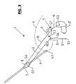
- the windshield wiper system designated in FIGS. 1 as being suitable, in particular, for use in a road vehicle consists, inter alia, of a kinematics 3 also comprising a wiper arm 2 and formed by further lever arms or designed as a Hegel gear.
- the kinematics 3 is designed in this way. that with her a provided on the wiper arm 2 wiper blade 4 via a vehicle windscreen 5 between a parking or starting position, in the Fig.
- the wiper blade 4 with its longitudinal extension (Wischblattlteilsachse WL) is arranged parallel or substantially parallel to a lower horizontal or substantially horizontal edge (line 5.1) of the windshield 5, and a maximum pivot position, ie a turning position is movable
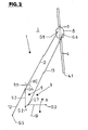
- the in the Fig. 2 is shown and in which the wiper blade 4 with its wiper blade longitudinal axis WL is parallel or substantially parallel to the so-called A-pillar of the vehicle body and the local edge (line 5.2) of the windshield 5, in each case at a predetermined distance from the relevant margin.
- the movement of the wiper blade 4 between these two end positions continues to be such that during the wiping process at least the entire legally prescribed field of view of the windshield 5 is detected, for example, when using the windshield wiper system 1 in a small car with a single wiper blade 4, the statutory field of view both the driver's side and the passenger's side.
- Lower wiper blade end 4.1 moves on a movement path or curve 6, which has a helical course, at its parking position of the wiper blade 4 corresponding end has a smaller radius of curvature than at the Turning position corresponding end and facing with its concave side in the intersection between the two lines 5.1 and 5.2.
- the wiper blade 4 which is a flat wiper blade in the illustrated embodiment, but may also be a wiper blade of another type, is connected fixedly in the middle with a wiper blade adapter 7 provided there with a joint or wiper blade carrier 8.
- the wiper arm 2 is articulated to the wiper blade carrier 8, specifically by means of the joint G1 about a pivot axis perpendicular to the plane of the front pane 5.
- the wiper arm 2 is fixed at its end remote from the joint G1 by means of an auxiliary joint HG pivotally mounted on a wiper arm 9, namely about an axis parallel to the plane of the windshield 5 and perpendicular to the axis of the joint G1, inter alia, a resilient concern of the wiper blade 4th to allow on the windshield 5 by a spring, not shown, and a replacement of the wiper blade 4.
- the wiper arm bearing element is designed as a double-armed lever with the helper arms or sections 9.1 and 9.2. When abutting against the windshield 5 wiper blade 4, the longitudinal extent of the wiper arm 2 is coaxially or approximately coaxially with the longitudinal extent of the section 9.1.
- the section 9.1 and the wiper arm 2 connected thereto via the joint HG thus form a common longer lever arm of a double-armed lever whose other, considerably shorter lever arm or section 9.2 forms an angle ⁇ with the lever arm consisting of the wiper arm 2 and the section 9.1 includes.
- This angle ⁇ is greater than 90 °, but less than 180 ° and opens to the wiper blade longitudinal axis WL and located in the parking position wiper blade 4 to the front glass 5 out.
- the angle ⁇ is in a range between 145 ° and 150 °.
- the free end of the section 9.2 is pivotally connected by means of a joint G2 to a drive lever 10 which, at its end remote from the joint G2, is fixed to a fixed, i.e. mounted on the vehicle body joint G3 and oscillating around the axis of this joint, i. is driven back and forth pivotally, as indicated in the figures with the double arrow A.
- the hinge G3 is formed by the bearing of an output shaft of a reversing electromotive wiper drive 11, i. the drive lever 10 is fixed at its end remote from the joint G2 on the shaft of this drive 11 such that the drive lever 10 extends radially away from this drive shaft.
- the wiper arm bearing element 9 is articulated with a hinge G4 at one end of a control lever 12 which is connected at its other end to a fixed, i. vehicle or body-side joint G5 is pivotally mounted.
- the two vehicle-side joints G3 and G5 are spatially spaced apart in such a way that both joints are outside the windscreen 5 and below the line 5.1 and the joint G3 both from the line 5.1, as well as from the line 5.2 a smaller distance than that Has joint G5.
- the wiper arm 2, the wiper arm bearing element 9 with its two sections 9.1 and 9.2, the drive lever 10, the control lever 12 and the joints G2, G3, G4 and G5 form a first four-bar linkage, with the wiper in addition to the pivoting movement of the wiper arm 2 and des Wiper blade 4 a lifting movement of the wiper arm 2 is achieved, as well as the curve 6 reflects.
- a coupling lever 13 is further articulated with one end, the other end is articulated by means of a joint G7 on the drive lever 10, between the two ends or joints G2 and G3, wherein the joint G7 the joint G2 is much closer than the joint G3.
- the joint G6 is located on the joint G1 facing away from the other side of the wiper blade longitudinal axis and has in the direction of this axis a slightly smaller distance from the wiper blade end 4.1 than the joint G1.
- the joint G7 is provided laterally on the drive lever 10 by a connecting line VL intersecting the axes of the joints G2 and G3, namely on the side of the line VL facing away from the wiper blade 4 when the wiper arm 2 is in the parking position and when the wiper blade 4 or wiper blade is in the reversing position Wiper arm 2 on the wiper blade 4 side facing the connecting line VL, so that in the parking position of the coupling lever 13 in the for the Figures 1 - 3 selected representation intersects the arranged in a different plane section 9.2 of the wiper arm bearing element 9 and when moving the wiper arm 2 from the parking position into the turning position, the axis of the joint G2 of the coupling lever 13 is cut once.
- the axes of all joints G1-G7 are oriented parallel to each other and perpendicular or approximately perpendicular to the plane of the windshield 5 and also perpendicular to the axis of the auxiliary joint HG.
- the coupling lever 11 is designed to be flexible at least for pivoting about the axis of the auxiliary joint HG, i. it consists for example of a flat material, e.g. made of plastic or spring steel and is then oriented with its surface sides parallel to the axis of the auxiliary joint HG and thus perpendicular to the axis of the joints G1 - G7.
- the training continues to be such that both in the parking position ( Fig. 1 ), as well as in the reversing position ( Fig. 2 )
- the longitudinal extent of the lever arm formed by the wiper arm 2 and the section 9.1 and the longitudinal extent of the coupling lever 13 are parallel or approximately parallel to each other.
- the kinematics is designed so that in both end positions, ie in the parking position ( Fig. 1 ) and in the maximum Pivoting position or reversing position ( Fig. 2 ) the connecting line VL between the joints G2 and G3 is approximately perpendicular to the wiper blade longitudinal axis WL.
- One unit is approximately 4 or 4.1 mm.
- the angle ⁇ is in the range between about 145 and 150 °
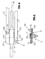
- FIGS. 4 and 5 still show in detail the wiper blade carrier 8 and the attachment of the wiper blade 4 on this wiper blade carrier.
- the example of a flat material by punching and Bending prepared wiper blade carrier 8 shaped so that it has a central, shaped as a U-section 8.1, which open to the front of the windshield 5 facing underside of the wiper blade carrier 8 and in which provided at the top of the wiper blade 4 wiper blade adapter 7 is picked up and attached.
- the section 8.1 or its legs are two lateral, wing-like sections 8.2 away, which lie in a common plane and where the wiper arm 2 are hinged to the joint G1 and the coupling arm 13 with the joint G6.
- the wiper arm bearing element 9 has two sections 9.1 and 9.2, and that the wiper arm 2 is connected to the section 9.1 via the auxiliary link HG.
- the wiper arm 2 it is also possible to attach the wiper arm 2 at its wiper blade carrier 8 remote end with a mounting portion releasably on Wischarmlagerelement 9, wherein the auxiliary joint HG is then provided between this attachment portion and the remaining wiper arm 2, so that, if necessary the wiper arm 2 can be easily assembled or disassembled.
- the joints G1 - G7 are designed so that they can be used wear-free over a long service life.
- Ball joints and / or sealed cylinder bearings are suitable for the joints, for example.
Landscapes
- Engineering & Computer Science (AREA)
- Mechanical Engineering (AREA)
- Pivots And Pivotal Connections (AREA)
- Transmission Devices (AREA)
- Window Of Vehicle (AREA)
- Vehicle Cleaning, Maintenance, Repair, Refitting, And Outriggers (AREA)
- Optical Head (AREA)
- Polishing Bodies And Polishing Tools (AREA)
Priority Applications (1)
| Application Number | Priority Date | Filing Date | Title |
|---|---|---|---|
| PL05701138T PL1708910T3 (pl) | 2004-01-26 | 2005-01-24 | Zespół wycieraczkowy do szyb pojazdów, w szczególności do pojazdów drogowych |
Applications Claiming Priority (2)
| Application Number | Priority Date | Filing Date | Title |
|---|---|---|---|
| DE102004003802A DE102004003802A1 (de) | 2004-01-26 | 2004-01-26 | Scheibenwischeranlage für Fahrzeuge, insbesondere Straßenfahrzeuge |
| PCT/EP2005/000647 WO2005070735A1 (de) | 2004-01-26 | 2005-01-24 | Scheibenwischeranlage für fahrzeuge, insbesondere strassenfahrzeuge |
Publications (2)
| Publication Number | Publication Date |
|---|---|
| EP1708910A1 EP1708910A1 (de) | 2006-10-11 |
| EP1708910B1 true EP1708910B1 (de) | 2008-11-19 |
Family
ID=34745110
Family Applications (1)
| Application Number | Title | Priority Date | Filing Date |
|---|---|---|---|
| EP05701138A Expired - Lifetime EP1708910B1 (de) | 2004-01-26 | 2005-01-24 | Scheibenwischeranlage für fahrzeuge, insbesondere strassenfahrzeuge |
Country Status (7)
| Country | Link |
|---|---|
| EP (1) | EP1708910B1 (pl) |
| JP (1) | JP2007518625A (pl) |
| CN (1) | CN1914074A (pl) |
| AT (1) | ATE414639T1 (pl) |
| DE (2) | DE102004003802A1 (pl) |
| PL (1) | PL1708910T3 (pl) |
| WO (1) | WO2005070735A1 (pl) |
Cited By (1)
| Publication number | Priority date | Publication date | Assignee | Title |
|---|---|---|---|---|
| WO2023107343A1 (en) * | 2021-12-06 | 2023-06-15 | Tesla, Inc. | Windshield wiper systems |
Families Citing this family (2)
| Publication number | Priority date | Publication date | Assignee | Title |
|---|---|---|---|---|
| FR2995853B1 (fr) * | 2012-09-27 | 2015-05-01 | Valeo Systemes Dessuyage | Dispositif de connexion pour systeme d'essuyage a deux bras d'actionnement et systeme d'essuyage comprenant un tel dispositif |
| CN108514373A (zh) * | 2018-03-29 | 2018-09-11 | 遂宁市长丰机械科技有限公司 | 玻璃窗的平行刮条雨刮器 |
Family Cites Families (16)
| Publication number | Priority date | Publication date | Assignee | Title |
|---|---|---|---|---|
| FR1280274A (fr) | 1961-02-07 | 1961-12-29 | Anderson Co | Ensemble d'essuie-glace |
| GB1234040A (pl) | 1968-03-13 | 1971-06-03 | ||
| US4245369A (en) * | 1979-07-02 | 1981-01-20 | Sprague Devices, Inc. | Straight sweep windshield wiper |
| JPS63212153A (ja) * | 1987-02-26 | 1988-09-05 | Nippon Soken Inc | 車両用ワイパ−装置 |
| DE3734201C2 (de) | 1987-10-09 | 1997-08-14 | Teves Gmbh Alfred | Scheibenwischeranlage, insbesondere für Kraftfahrzeuge |
| FR2625152B1 (fr) * | 1987-12-24 | 1990-06-08 | Marchal Equip Auto | Dispositif d'essuie-glace |
| JPH01229747A (ja) * | 1988-03-10 | 1989-09-13 | Nippon Soken Inc | 車両用ワイパー装置 |
| JPH06156201A (ja) * | 1992-11-21 | 1994-06-03 | Sohei Shiroshita | 全面ワイパー2 |
| JP2938339B2 (ja) * | 1994-03-16 | 1999-08-23 | 日野自動車工業株式会社 | ウインドシールドワイパ装置 |
| DE19501211A1 (de) | 1995-01-17 | 1996-07-18 | Teves Gmbh Alfred | Wischarm für eine hubgesteuerte Scheibenwischvorrichtung |
| DE19546862A1 (de) * | 1995-12-15 | 1997-06-19 | Bosch Gmbh Robert | Wischanlage von Scheiben von Kraftfahrzeugen |
| JPH10264772A (ja) * | 1997-03-25 | 1998-10-06 | Asmo Co Ltd | ワイパ装置 |
| JPH1199911A (ja) * | 1997-09-26 | 1999-04-13 | Mitsuba Corp | ワイパ装置 |
| JPH11180255A (ja) * | 1997-12-25 | 1999-07-06 | Asmo Co Ltd | 車両用ワイパ装置 |
| DE19807062A1 (de) | 1998-02-20 | 1999-08-26 | Itt Mfg Enterprises Inc | Viergelenkwischarm für eine Scheibenwischeranlage |
| JP2001315621A (ja) * | 2000-05-08 | 2001-11-13 | Masuhiro Kawano | スリットを設けたカムと伸縮式シャフトを用いた全面ワイパー |
-
2004
- 2004-01-26 DE DE102004003802A patent/DE102004003802A1/de not_active Withdrawn
-
2005
- 2005-01-24 CN CNA2005800032586A patent/CN1914074A/zh active Pending
- 2005-01-24 DE DE502005006000T patent/DE502005006000D1/de not_active Expired - Lifetime
- 2005-01-24 WO PCT/EP2005/000647 patent/WO2005070735A1/de not_active Ceased
- 2005-01-24 AT AT05701138T patent/ATE414639T1/de not_active IP Right Cessation
- 2005-01-24 JP JP2006550066A patent/JP2007518625A/ja active Pending
- 2005-01-24 PL PL05701138T patent/PL1708910T3/pl unknown
- 2005-01-24 EP EP05701138A patent/EP1708910B1/de not_active Expired - Lifetime
Cited By (1)
| Publication number | Priority date | Publication date | Assignee | Title |
|---|---|---|---|---|
| WO2023107343A1 (en) * | 2021-12-06 | 2023-06-15 | Tesla, Inc. | Windshield wiper systems |
Also Published As
| Publication number | Publication date |
|---|---|
| CN1914074A (zh) | 2007-02-14 |
| DE102004003802A1 (de) | 2005-08-11 |
| WO2005070735A1 (de) | 2005-08-04 |
| JP2007518625A (ja) | 2007-07-12 |
| PL1708910T3 (pl) | 2009-04-30 |
| DE502005006000D1 (de) | 2009-01-02 |
| EP1708910A1 (de) | 2006-10-11 |
| ATE414639T1 (de) | 2008-12-15 |
Similar Documents
| Publication | Publication Date | Title |
|---|---|---|
| EP1940660B1 (de) | Scheibenwischerarm | |
| EP0351528A2 (de) | Wischvorrichtung für gekrümmte Scheiben von Kraftfahrzeugen | |
| EP1436178B1 (de) | Wischeranlage | |
| DE4444066B4 (de) | Scheibenwischvorrichtung für Fahrzeuge | |
| DE10048122B4 (de) | Luftleitvorrichtung für ein Kraftfahrzeug | |
| EP1708910B1 (de) | Scheibenwischeranlage für fahrzeuge, insbesondere strassenfahrzeuge | |
| DE102004061088A1 (de) | Wischeinrichtung | |
| EP1029758A2 (de) | Wischanlage | |
| DE3802360A1 (de) | Scheibenwischer | |
| DE19837021A1 (de) | Scheibenwischervorrichtung | |
| DE102004016251A1 (de) | Wischarmanordnung | |
| EP1586471B1 (de) | Anhängerkupplung | |
| DE102021205639B3 (de) | Scheibenwischer sowie Fahrzeug mit einem solchen Scheibenwischer | |
| EP1140583B1 (de) | Scheibenwischanlage für fahrzeug und verfahren zum betreiben eines wischhebelgestänges | |
| EP1824713B1 (de) | Scheibenwischanlage für fahrzeuge, insbesondere für kraftfahrzeuge | |
| EP0717688B1 (de) | Wischarm | |
| EP1844995A2 (de) | Scheibenwischer | |
| WO2003070532A1 (de) | Kraftfahrzeug-waschstrasse mit einer ausbalancierten dachrolle | |
| DE102004026552B4 (de) | Antriebsvorrichtung für einen Wischarm einer Scheibenwischeranlage | |
| DE4214679B4 (de) | Wischarm für eine Scheibenwischeranlage eines Kraftfahrzeugs | |
| DE19634718C1 (de) | Wischvorrichtung für Fahrzeugscheiben | |
| DE102005015038A1 (de) | Scheibenwischer | |
| DE102004056676B4 (de) | Wischanlage für Fahrzeugscheiben | |
| DE10326007A1 (de) | Einrichtung zum Anheben eines in eine Parkstellung verfahrbaren Scheibenwischers | |
| DE10301796A1 (de) | Sonnenblende für ein Kraftfahrzeug |
Legal Events
| Date | Code | Title | Description |
|---|---|---|---|
| PUAI | Public reference made under article 153(3) epc to a published international application that has entered the european phase |
Free format text: ORIGINAL CODE: 0009012 |
|
| 17P | Request for examination filed |
Effective date: 20060707 |
|
| AK | Designated contracting states |
Kind code of ref document: A1 Designated state(s): AT BE BG CH CY CZ DE DK EE ES FI FR GB GR HU IE IS IT LI LT LU MC NL PL PT RO SE SI SK TR |
|
| DAX | Request for extension of the european patent (deleted) | ||
| 17Q | First examination report despatched |
Effective date: 20070522 |
|
| GRAP | Despatch of communication of intention to grant a patent |
Free format text: ORIGINAL CODE: EPIDOSNIGR1 |
|
| GRAS | Grant fee paid |
Free format text: ORIGINAL CODE: EPIDOSNIGR3 |
|
| GRAA | (expected) grant |
Free format text: ORIGINAL CODE: 0009210 |
|
| AK | Designated contracting states |
Kind code of ref document: B1 Designated state(s): AT BE BG CH CY CZ DE DK EE ES FI FR GB GR HU IE IS IT LI LT LU MC NL PL PT RO SE SI SK TR |
|
| REG | Reference to a national code |
Ref country code: GB Ref legal event code: FG4D Free format text: NOT ENGLISH |
|
| REG | Reference to a national code |
Ref country code: CH Ref legal event code: EP |
|
| REG | Reference to a national code |
Ref country code: IE Ref legal event code: FG4D Free format text: LANGUAGE OF EP DOCUMENT: GERMAN |
|
| REF | Corresponds to: |
Ref document number: 502005006000 Country of ref document: DE Date of ref document: 20090102 Kind code of ref document: P |
|
| REG | Reference to a national code |
Ref country code: RO Ref legal event code: EPE |
|
| LTIE | Lt: invalidation of european patent or patent extension |
Effective date: 20081119 |
|
| PG25 | Lapsed in a contracting state [announced via postgrant information from national office to epo] |
Ref country code: LT Free format text: LAPSE BECAUSE OF FAILURE TO SUBMIT A TRANSLATION OF THE DESCRIPTION OR TO PAY THE FEE WITHIN THE PRESCRIBED TIME-LIMIT Effective date: 20081119 Ref country code: ES Free format text: LAPSE BECAUSE OF FAILURE TO SUBMIT A TRANSLATION OF THE DESCRIPTION OR TO PAY THE FEE WITHIN THE PRESCRIBED TIME-LIMIT Effective date: 20090301 |
|
| REG | Reference to a national code |
Ref country code: PL Ref legal event code: T3 |
|
| NLV1 | Nl: lapsed or annulled due to failure to fulfill the requirements of art. 29p and 29m of the patents act | ||
| PG25 | Lapsed in a contracting state [announced via postgrant information from national office to epo] |
Ref country code: SI Free format text: LAPSE BECAUSE OF FAILURE TO SUBMIT A TRANSLATION OF THE DESCRIPTION OR TO PAY THE FEE WITHIN THE PRESCRIBED TIME-LIMIT Effective date: 20081119 Ref country code: NL Free format text: LAPSE BECAUSE OF FAILURE TO SUBMIT A TRANSLATION OF THE DESCRIPTION OR TO PAY THE FEE WITHIN THE PRESCRIBED TIME-LIMIT Effective date: 20081119 Ref country code: FI Free format text: LAPSE BECAUSE OF FAILURE TO SUBMIT A TRANSLATION OF THE DESCRIPTION OR TO PAY THE FEE WITHIN THE PRESCRIBED TIME-LIMIT Effective date: 20081119 Ref country code: IS Free format text: LAPSE BECAUSE OF FAILURE TO SUBMIT A TRANSLATION OF THE DESCRIPTION OR TO PAY THE FEE WITHIN THE PRESCRIBED TIME-LIMIT Effective date: 20090319 |
|
| REG | Reference to a national code |
Ref country code: HU Ref legal event code: AG4A Ref document number: E005156 Country of ref document: HU |
|
| PGFP | Annual fee paid to national office [announced via postgrant information from national office to epo] |
Ref country code: GB Payment date: 20090109 Year of fee payment: 5 |
|
| REG | Reference to a national code |
Ref country code: IE Ref legal event code: FD4D |
|
| PG25 | Lapsed in a contracting state [announced via postgrant information from national office to epo] |
Ref country code: IE Free format text: LAPSE BECAUSE OF FAILURE TO SUBMIT A TRANSLATION OF THE DESCRIPTION OR TO PAY THE FEE WITHIN THE PRESCRIBED TIME-LIMIT Effective date: 20081119 Ref country code: EE Free format text: LAPSE BECAUSE OF FAILURE TO SUBMIT A TRANSLATION OF THE DESCRIPTION OR TO PAY THE FEE WITHIN THE PRESCRIBED TIME-LIMIT Effective date: 20081119 Ref country code: DK Free format text: LAPSE BECAUSE OF FAILURE TO SUBMIT A TRANSLATION OF THE DESCRIPTION OR TO PAY THE FEE WITHIN THE PRESCRIBED TIME-LIMIT Effective date: 20081119 Ref country code: BG Free format text: LAPSE BECAUSE OF FAILURE TO SUBMIT A TRANSLATION OF THE DESCRIPTION OR TO PAY THE FEE WITHIN THE PRESCRIBED TIME-LIMIT Effective date: 20090219 |
|
| PG25 | Lapsed in a contracting state [announced via postgrant information from national office to epo] |
Ref country code: SE Free format text: LAPSE BECAUSE OF FAILURE TO SUBMIT A TRANSLATION OF THE DESCRIPTION OR TO PAY THE FEE WITHIN THE PRESCRIBED TIME-LIMIT Effective date: 20090219 Ref country code: MC Free format text: LAPSE BECAUSE OF NON-PAYMENT OF DUE FEES Effective date: 20090131 Ref country code: PT Free format text: LAPSE BECAUSE OF FAILURE TO SUBMIT A TRANSLATION OF THE DESCRIPTION OR TO PAY THE FEE WITHIN THE PRESCRIBED TIME-LIMIT Effective date: 20090420 |
|
| REG | Reference to a national code |
Ref country code: CH Ref legal event code: PL |
|
| PLBE | No opposition filed within time limit |
Free format text: ORIGINAL CODE: 0009261 |
|
| STAA | Information on the status of an ep patent application or granted ep patent |
Free format text: STATUS: NO OPPOSITION FILED WITHIN TIME LIMIT |
|
| PG25 | Lapsed in a contracting state [announced via postgrant information from national office to epo] |
Ref country code: SK Free format text: LAPSE BECAUSE OF FAILURE TO SUBMIT A TRANSLATION OF THE DESCRIPTION OR TO PAY THE FEE WITHIN THE PRESCRIBED TIME-LIMIT Effective date: 20081119 |
|
| 26N | No opposition filed |
Effective date: 20090820 |
|
| PG25 | Lapsed in a contracting state [announced via postgrant information from national office to epo] |
Ref country code: LI Free format text: LAPSE BECAUSE OF NON-PAYMENT OF DUE FEES Effective date: 20090131 Ref country code: CH Free format text: LAPSE BECAUSE OF NON-PAYMENT OF DUE FEES Effective date: 20090131 |
|
| PG25 | Lapsed in a contracting state [announced via postgrant information from national office to epo] |
Ref country code: AT Free format text: LAPSE BECAUSE OF NON-PAYMENT OF DUE FEES Effective date: 20090124 |
|
| GBPC | Gb: european patent ceased through non-payment of renewal fee |
Effective date: 20100124 |
|
| PG25 | Lapsed in a contracting state [announced via postgrant information from national office to epo] |
Ref country code: GR Free format text: LAPSE BECAUSE OF FAILURE TO SUBMIT A TRANSLATION OF THE DESCRIPTION OR TO PAY THE FEE WITHIN THE PRESCRIBED TIME-LIMIT Effective date: 20090220 |
|
| PG25 | Lapsed in a contracting state [announced via postgrant information from national office to epo] |
Ref country code: GB Free format text: LAPSE BECAUSE OF NON-PAYMENT OF DUE FEES Effective date: 20100124 |
|
| PG25 | Lapsed in a contracting state [announced via postgrant information from national office to epo] |
Ref country code: IT Free format text: LAPSE BECAUSE OF FAILURE TO SUBMIT A TRANSLATION OF THE DESCRIPTION OR TO PAY THE FEE WITHIN THE PRESCRIBED TIME-LIMIT Effective date: 20081119 |
|
| PG25 | Lapsed in a contracting state [announced via postgrant information from national office to epo] |
Ref country code: LU Free format text: LAPSE BECAUSE OF NON-PAYMENT OF DUE FEES Effective date: 20090124 |
|
| PG25 | Lapsed in a contracting state [announced via postgrant information from national office to epo] |
Ref country code: CY Free format text: LAPSE BECAUSE OF FAILURE TO SUBMIT A TRANSLATION OF THE DESCRIPTION OR TO PAY THE FEE WITHIN THE PRESCRIBED TIME-LIMIT Effective date: 20081119 |
|
| REG | Reference to a national code |
Ref country code: FR Ref legal event code: PLFP Year of fee payment: 12 |
|
| PGFP | Annual fee paid to national office [announced via postgrant information from national office to epo] |
Ref country code: CZ Payment date: 20161219 Year of fee payment: 13 |
|
| REG | Reference to a national code |
Ref country code: FR Ref legal event code: PLFP Year of fee payment: 13 |
|
| PGFP | Annual fee paid to national office [announced via postgrant information from national office to epo] |
Ref country code: RO Payment date: 20170103 Year of fee payment: 13 |
|
| PGFP | Annual fee paid to national office [announced via postgrant information from national office to epo] |
Ref country code: HU Payment date: 20161220 Year of fee payment: 13 |
|
| REG | Reference to a national code |
Ref country code: FR Ref legal event code: PLFP Year of fee payment: 14 |
|
| PG25 | Lapsed in a contracting state [announced via postgrant information from national office to epo] |
Ref country code: RO Free format text: LAPSE BECAUSE OF NON-PAYMENT OF DUE FEES Effective date: 20180124 Ref country code: HU Free format text: LAPSE BECAUSE OF NON-PAYMENT OF DUE FEES Effective date: 20180125 |
|
| PG25 | Lapsed in a contracting state [announced via postgrant information from national office to epo] |
Ref country code: CZ Free format text: LAPSE BECAUSE OF NON-PAYMENT OF DUE FEES Effective date: 20180124 |
|
| PGFP | Annual fee paid to national office [announced via postgrant information from national office to epo] |
Ref country code: PL Payment date: 20191218 Year of fee payment: 16 |
|
| PGFP | Annual fee paid to national office [announced via postgrant information from national office to epo] |
Ref country code: BE Payment date: 20200127 Year of fee payment: 16 |
|
| PGFP | Annual fee paid to national office [announced via postgrant information from national office to epo] |
Ref country code: TR Payment date: 20200114 Year of fee payment: 16 |
|
| REG | Reference to a national code |
Ref country code: BE Ref legal event code: MM Effective date: 20210131 |
|
| PG25 | Lapsed in a contracting state [announced via postgrant information from national office to epo] |
Ref country code: BE Free format text: LAPSE BECAUSE OF NON-PAYMENT OF DUE FEES Effective date: 20210131 |
|
| PG25 | Lapsed in a contracting state [announced via postgrant information from national office to epo] |
Ref country code: PL Free format text: LAPSE BECAUSE OF NON-PAYMENT OF DUE FEES Effective date: 20210124 |
|
| PGFP | Annual fee paid to national office [announced via postgrant information from national office to epo] |
Ref country code: FR Payment date: 20230125 Year of fee payment: 19 |
|
| PGFP | Annual fee paid to national office [announced via postgrant information from national office to epo] |
Ref country code: DE Payment date: 20230112 Year of fee payment: 19 |
|
| P01 | Opt-out of the competence of the unified patent court (upc) registered |
Effective date: 20230603 |
|
| REG | Reference to a national code |
Ref country code: DE Ref legal event code: R119 Ref document number: 502005006000 Country of ref document: DE |
|
| PG25 | Lapsed in a contracting state [announced via postgrant information from national office to epo] |
Ref country code: DE Free format text: LAPSE BECAUSE OF NON-PAYMENT OF DUE FEES Effective date: 20240801 |
|
| PG25 | Lapsed in a contracting state [announced via postgrant information from national office to epo] |
Ref country code: FR Free format text: LAPSE BECAUSE OF NON-PAYMENT OF DUE FEES Effective date: 20240131 |
|
| PG25 | Lapsed in a contracting state [announced via postgrant information from national office to epo] |
Ref country code: FR Free format text: LAPSE BECAUSE OF NON-PAYMENT OF DUE FEES Effective date: 20240131 Ref country code: DE Free format text: LAPSE BECAUSE OF NON-PAYMENT OF DUE FEES Effective date: 20240801 |