EP1707996B1 - Herstellungsverfahren eines optischen Verzögerungsfilms durch Infiltrieren eines anisotropischen Flüssigkristallmaterials in einen Polymerfilm - Google Patents
Herstellungsverfahren eines optischen Verzögerungsfilms durch Infiltrieren eines anisotropischen Flüssigkristallmaterials in einen Polymerfilm Download PDFInfo
- Publication number
- EP1707996B1 EP1707996B1 EP05806934A EP05806934A EP1707996B1 EP 1707996 B1 EP1707996 B1 EP 1707996B1 EP 05806934 A EP05806934 A EP 05806934A EP 05806934 A EP05806934 A EP 05806934A EP 1707996 B1 EP1707996 B1 EP 1707996B1
- Authority
- EP
- European Patent Office
- Prior art keywords
- retardation
- film
- refractive index
- polymer film
- liquid crystal
- Prior art date
- Legal status (The legal status is an assumption and is not a legal conclusion. Google has not performed a legal analysis and makes no representation as to the accuracy of the status listed.)
- Expired - Fee Related
Links
Images


Classifications
-
- C—CHEMISTRY; METALLURGY
- C09—DYES; PAINTS; POLISHES; NATURAL RESINS; ADHESIVES; COMPOSITIONS NOT OTHERWISE PROVIDED FOR; APPLICATIONS OF MATERIALS NOT OTHERWISE PROVIDED FOR
- C09K—MATERIALS FOR MISCELLANEOUS APPLICATIONS, NOT PROVIDED FOR ELSEWHERE
- C09K19/00—Liquid crystal materials
- C09K19/04—Liquid crystal materials characterised by the chemical structure of the liquid crystal components, e.g. by a specific unit
- C09K19/38—Polymers
-
- G—PHYSICS
- G02—OPTICS
- G02F—OPTICAL DEVICES OR ARRANGEMENTS FOR THE CONTROL OF LIGHT BY MODIFICATION OF THE OPTICAL PROPERTIES OF THE MEDIA OF THE ELEMENTS INVOLVED THEREIN; NON-LINEAR OPTICS; FREQUENCY-CHANGING OF LIGHT; OPTICAL LOGIC ELEMENTS; OPTICAL ANALOGUE/DIGITAL CONVERTERS
- G02F1/00—Devices or arrangements for the control of the intensity, colour, phase, polarisation or direction of light arriving from an independent light source, e.g. switching, gating or modulating; Non-linear optics
- G02F1/01—Devices or arrangements for the control of the intensity, colour, phase, polarisation or direction of light arriving from an independent light source, e.g. switching, gating or modulating; Non-linear optics for the control of the intensity, phase, polarisation or colour
- G02F1/13—Devices or arrangements for the control of the intensity, colour, phase, polarisation or direction of light arriving from an independent light source, e.g. switching, gating or modulating; Non-linear optics for the control of the intensity, phase, polarisation or colour based on liquid crystals, e.g. single liquid crystal display cells
- G02F1/133—Constructional arrangements; Operation of liquid crystal cells; Circuit arrangements
- G02F1/1333—Constructional arrangements; Manufacturing methods
- G02F1/1335—Structural association of cells with optical devices, e.g. polarisers or reflectors
- G02F1/13363—Birefringent elements, e.g. for optical compensation
-
- C—CHEMISTRY; METALLURGY
- C09—DYES; PAINTS; POLISHES; NATURAL RESINS; ADHESIVES; COMPOSITIONS NOT OTHERWISE PROVIDED FOR; APPLICATIONS OF MATERIALS NOT OTHERWISE PROVIDED FOR
- C09K—MATERIALS FOR MISCELLANEOUS APPLICATIONS, NOT PROVIDED FOR ELSEWHERE
- C09K19/00—Liquid crystal materials
-
- G—PHYSICS
- G02—OPTICS
- G02B—OPTICAL ELEMENTS, SYSTEMS OR APPARATUS
- G02B5/00—Optical elements other than lenses
- G02B5/30—Polarising elements
-
- G—PHYSICS
- G02—OPTICS
- G02B—OPTICAL ELEMENTS, SYSTEMS OR APPARATUS
- G02B5/00—Optical elements other than lenses
- G02B5/30—Polarising elements
- G02B5/3016—Polarising elements involving passive liquid crystal elements
-
- C—CHEMISTRY; METALLURGY
- C09—DYES; PAINTS; POLISHES; NATURAL RESINS; ADHESIVES; COMPOSITIONS NOT OTHERWISE PROVIDED FOR; APPLICATIONS OF MATERIALS NOT OTHERWISE PROVIDED FOR
- C09K—MATERIALS FOR MISCELLANEOUS APPLICATIONS, NOT PROVIDED FOR ELSEWHERE
- C09K2219/00—Aspects relating to the form of the liquid crystal [LC] material, or by the technical area in which LC material are used
- C09K2219/03—Aspects relating to the form of the liquid crystal [LC] material, or by the technical area in which LC material are used in the form of films, e.g. films after polymerisation of LC precursor
-
- C—CHEMISTRY; METALLURGY
- C09—DYES; PAINTS; POLISHES; NATURAL RESINS; ADHESIVES; COMPOSITIONS NOT OTHERWISE PROVIDED FOR; APPLICATIONS OF MATERIALS NOT OTHERWISE PROVIDED FOR
- C09K—MATERIALS FOR MISCELLANEOUS APPLICATIONS, NOT PROVIDED FOR ELSEWHERE
- C09K2323/00—Functional layers of liquid crystal optical display excluding electroactive liquid crystal layer characterised by chemical composition
- C09K2323/03—Viewing layer characterised by chemical composition
- C09K2323/031—Polarizer or dye
Definitions
- the present invention relates to a method for producing a retardation film used in a state installed in a display device such as a liquid crystal display.
- FIG. 22 As a conventional common liquid crystal display, as shown in FIG. 22 , one comprising a polarizing plate 102A on an incident side, a polarizing plate 102B on an outgoing side and a liquid crystal cell 104 can be presented.
- the polarizing plates 102A and 102B are constructed so as to selectively transmit only the linear polarization having an oscillation surface in a predetermined oscillation direction (shown schematically by an arrow in the figure), and are disposed facing with each other in a cross nicol state such that the oscillation directions thereof have a relationship perpendicular with each other.
- the liquid crystal cell 104 including a large number of cells corresponding to pixels, is disposed in between the polarizing plate 102A and polarizing plate 102B.
- liquid crystal display 100 for example, in the case of the liquid crystal cell 104 adopting a VA (vertical alignment) system, in which a nematic liquid crystal having a negative dielectric anisotropy is sealed (the liquid crystal director is shown schematically by a dotted line in the figure), the linear polarization transmitted through the polarizing plate 102A on the incident side is transmitted without being its phase shifted, at the time of being transmitted through a non-driven state cell part among the liquid crystal cell 104, so as to be blocked by the polarizing plate 102B on the outgoing side.
- VA vertical alignment
- the phase of the linear polarization is shifted so that light of an amount according to the phase shift amount is transmitted through and outgoes from the polarizing plate 102B on the incident side. Accordingly, by optionally controlling the driving voltage of the liquid crystal cell 104 per each cell, a desired image can be displayed on the side of the polarizing plate 102B on the outgoing side.
- the liquid crystal display 100 is not limited to ones having the above-mentioned configuration of the light transmission and blockage.
- a liquid crystal display in which the outgoing light from the non-driven state cell part among the liquid crystal cell 104 is transmitted through and outgoes from the polarizing plate 102B on the outgoing side,-and in which the outgoing light from the driven state cell part is blocked by the polarizing plate 102B on the outgoing side, is also proposed.
- the phase of the incident light entering in an inclined direction to the normal line of the liquid crystal cell 104 is shifted when the light is transmitted through the liquid crystal cell 104 so as to be elliptically polarized.
- This phenomenon is derived from the liquid crystal molecules, aligned in the perpendicular direction in the liquid crystal cell 104, acting as a positive C plate.
- the magnitude of the retardation generated with respect to the light transmitted through the liquid crystal cell 104 (transmitted light) depends also on the double refractive value of the liquid crystal molecules sealed in the liquid crystal cell 104, the thickness of the liquid crystal cell 104, the wavelength of the transmitted light or the like.
- a liquid crystal display in which the optical compensation is carried out by using a retardation layer (retardation layer showing the property of double refraction) comprising a disc like compound and by disposing such retardation layer in between liquid crystal cells and a polarizing plate, is also known.
- a retardation layer retardation layer showing the property of double refraction
- the phase of the linear polarization incident entering in an inclined direction to the normal line of the retardation layer, is shifted when it is transmitted through the retardation layer so as to be elliptically polarized.
- This phenomenon is derived from the molecular alignment of the cholesteric regularity and the disc like compound itself acting as a negative C plate.
- the magnitude of the retardation generated with respect to the light transmitted through the retardation layer depends also on the double refractive value of the liquid crystal molecules in the retardation layer, the thickness of the retardation layer, the wavelength of the transmitted light or the like.
- the problem of the visual angle dependency of the liquid crystal display can dramatically be improved by optionally designing the retardation layer such that the retardation generated in the VA system liquid crystal cells, which act as the positive C plate, and the retardation generated in the retardation layer, which act as the negative C plate, offset with each other.
- the visual angle dependency of the polarizing plate can be improved, with the remaining positive plate C component and an A plate prepared separately, by making the sum of the retardation values in the thickness direction of the above-mentioned positive C plate and the above-mentioned negative C plate positive. That is, by making the absolute value of the retardation value in the thickness direction of the above-mentioned negative C plate smaller than the absolute value of the retardation value in the thickness direction of the above-mentioned positive C plate.
- the improvement of the visual angle dependency of the polarizing plate with the positive C plate and A plate is disclosed in, for example, J. Chen et al., SID98 Digest, p315 (1998 ) and T. Ishinabe et al., SID00 Digest, p1094 (2000 ).
- the retardation layer there is a problem of an adhesion between the retardation layer and the base material (for example, the TAC (cellulose triacetate film) as the protecting film for the polarizing layer).
- the base material for example, the TAC (cellulose triacetate film) as the protecting film for the polarizing layer.
- the retardation increasing agent in general is hydrophobic
- the front and rear surfaces of the cellulose acetate film become hydrophobic so that a problem is involved in that the adhering property at the time of laminating the retardation layer on a polarizing plate comprising a hydrophilic resin such as a polyvinyl alcohol.
- the mixable amount of the retardation increasing agent is substantially limited, and thereby the retardation value to be obtained is limited as a result.
- JP 2004 050516 describes a cellulose acrylate film containing 2 to 20 mass-% of water and at least one kind of additive selected from the group consisting of a plasticizer, an anti-deterioration agent, a retardation boosting agent, an ultraviolet absorbing agent and an aromatic compound.
- JP 2003 043250 describes an optical compensation sheet consisting of a polymer film containing an aromatic compound, wherein the aromatic compound does not concentrate on the film surface in the distribution of the aromatic compound in the film thickness direction and the aromatic compound hardly separates on the film surface even after the lapse of a long time.
- US 2006/0182896 describes an optical film, which includes a laminate of a base layer and a birefringent layer, and which is excellent in adhesiveness between the base layer and the birefringent layer.
- the present invention has been achieved in view of the above-mentioned problems, and an object thereof is to provide method for producing a highly reliable retardation film having a refractive index anisotropy without the problems of peeling off of the retardation layer from the base material or the like generated in the case of forming the retardation layer as above mentioned, capable of enlarging the range of the thickness direction and in-plane direction retardation values to be obtained, easily obtaining optional thickness direction and in-plane direction retardation values even for a small amount, and capable of improving the adhering property with a hydrophilic film such as a polarizing layer, among them in particular, a biaxial retardation film.
- a retardation film which is optically biaxial comprising a polymer film containing a material having refractive index anisotropy (hereinafter, it may be referred to also as a refractive index anisotropic material), wherein the material having refractive index anisotropy has a concentration gradient in a thickness direction of the polymer film.
- a material having refractive index anisotropy hereinafter, it may be referred to also as a refractive index anisotropic material
- a retardation film which is optically biaxial comprising a polymer film infiltrated with a material having refractive index anisotropy.
- a retardation film comprising a polymer film containing a material having refractive index anisotropy, and the material having refractive index anisotropy has a concentration gradient in a thickness direction of the polymer film, and the polymer film is oriented.
- a retardation film comprising a polymer film infiltrated with a material having refractive index anisotropy, and the polymer film is oriented.
- the present invention for example, by coating a coating solution in which a refractive index anisotropic material is dissolved in a solvent, on the surface of a polymer film so as to swell the polymer film for infiltrating with the refractive index anisotropic material, it is possible to easily fill the vicinity of the polymer film surface with the refractive index anisotropic material. Thereby, a retardation film having concentration gradient of the refractive index anisotropic material in a direction of the above-mentioned polymer film thickness, can be obtained.
- a retardation film which is optically biaxial can be obtained.
- the retardation value mainly in the thickness direction, and furthermore, in the in-plane direction as the retardation film can easily be changed.
- the retardation value mainly in the in-plane direction, and furthermore, in the thickness direction as the retardation film can easily be changed.
- the ranges of the thickness direction and in-plane direction retardation values to be obtained can be enlarged, the values of the thickness direction retardation and the in-plane direction retardation can desirably controlled independently with ease, and furthermore, a retardation film having the optional thickness direction and in-plane direction retardation values can easily be obtained in a small lot.
- the present invention since it is not a conventional retardation film produced by laminating a retardation layer as another layer on a base material so as to be laminated and formed, a problem of the peeling off of the retardation layer from the base material is not generated, and thus there is an advantage that the reliability such as the heat resistance and the water resistance (durability in term of the delamination with respect to repetition of the coldness and the heat in the use environment or contact with water), the alkaline resistance (saponification resistance), and the reworking property (repeated usability) can be improved.
- the above-mentioned polymer film is oriented.
- a retardation film having a concentration gradient of the refractive index anisotropic material in the thickness direction of the polymer film or by coating a coating solution in which a refractive index anisotropic material is dissolved in a solvent on the surface of the polymer film preliminarily oriented, a retardation film which is optically biaxial can easily be obtained.
- nx is a refractive index along a slow axis in the in-plane direction of the film
- ny is a refractive index along a fast axis in the in-plane direction of the film
- nz is a refractive index along a thickness direction of the film.
- a direction of a principal refractive index of the above-mentioned film may be inclined with respect to in-plane directions of the film and a thickness direction of the film.
- the view angle improving effect can be improved corresponding to further various applications and design demands so that the designing freedom can be widened as well.
- the above-mentioned polymer film has regularity in the refractive index.
- the refractive index regularity of the polymer film can be reinforced by the refractive index anisotropic material to be filled, so that a retardation film having various characteristics can be obtained.
- the refractive index anisotropic material is a material having liquid crystallinity.
- the material having the liquid crystallinity a liquid crystal structure may be provided when the material is filled in the polymer film, so that the effect can be imparted effectively to the polymer film.
- the molecular structure of the refractive index anisotropic material is in a shape of a rod.
- the refractive index anisotropic material having a structure in the shape of a rod the refractive index regularity of the above-mentioned polymer film can be reinforced.
- the refractive index anisotropic material has a polymerizable functional group.
- the material having refractive index anisotropy comprises a material having a polymerizable functional group and a material having no a polymerizable functional group.
- the retardation function can be further reinforced by the material having no polymerizable functional group, and the film reliability can be improved by the material having a polymerizable functional group.
- the concentration gradient of the material having refractive index anisotropy in a thickness direction of the polymer film has high concentration on one surface side of the polymer film and becomes low concentration toward the other surface side.
- contact angels of the retardation film to pure water are different between one surface and the other surface, in the case where the concentration gradient of the material having refractive index anisotropy in a thickness direction of the polymer film has high concentration on one surface side of the polymer film and becomes low concentration toward the other surface side.
- a polarizing film in the case of providing a polarizing film by for example directly laminating a hydrophilic resin based polarizing layer having a PVA base material on the retardation film, if the polarizing layer is laminated on the surface having a lower contact angle, a polarizing film can be obtained without inhibiting the adhesion even in the case a water based adhesive is used.
- the concentration gradient of the material having refractive index anisotropy in a thickness direction of the polymer film has high concentration on both surface sides of the polymer film and becomes low concentration toward a central part.
- the concentration gradient of the material having refractive index anisotropy in a thickness direction of the polymer film varies continuously.
- the peeling strength is strengthened so that the reliability such as the heat resistance and the water resistance, the alkaline resistance, the reworking property can be improved.
- the reliability can be improved while providing a desired retardation owing to reinforcement of the retardation and reinforcement of the peeling strength, the heat resistance and the water resistance.
- the retardation films of the first, second, third and fourth disclosures it is preferable to have a region which contains no material having refractive index anisotropy. Since the nature of the polymer film remains as it is in the region which contains no refractive index anisotropic material, for example the preferable adhesion of the polymer film itself can be utilized. Furthermore, although the retardation reinforcing region containing the refractive index anisotropic material may have the strength weakened, since the region which contains no refractive index anisotropic material is provided as mentioned above, the strength as the retardation film can be maintained, and thus it is advantageous.
- the ranges of the thickness direction and in-plane direction retardation values to be substantially obtained can be enlarged, and in this case the view
- the retardation films of the first, second, third and fourth disclosures it is preferable to show an in-plane direction retardation of 10 to 150 nm and has a haze value of 1% or less measured in accordance with JIS-K7136. In this case, the view angle improving effect can be improved without disturbing the polarizing state.
- the retardation value, in the visible light range, of the retardation film on the shorter wavelength side is larger than that of the longer wavelength side.
- the retardation value of a liquid crystal material used for a liquid crystal layer of a liquid crystal display, in the visible light range, on the shorter wavelength side is larger than that of the longer wavelength side. Therefore, in the case of using the retardation film of the present invention as, for example, an optical compensating plate, there is an advantage that the compensation can be carried out in the all wavelength range in the visible light range.
- the retardation value, in the visible light range, of the retardation film on the longer wavelength side may be larger than that of the shorter wavelength side.
- a retardation film when such a retardation film is used as, for example, a polarizing plate in a state laminated on a polarizing film, it is advantageous in that the excellent light leakage compensation can be provided, and thus it is preferable.
- the above-mentioned retardation films of the first, second, third and fourth disclosures are capable of being rolled into a cylindrical form having a minimum diameter of 6 inches or less. It is preferable that the retardation film is formed into a long continuous film (also referred to as a web) and is rolled on a cylinder so as to be in a form of roll at the time of storage, transportation and standby for a process, other than production, inspection and post process) in order to improve the mass productivity and the production yield.
- a long continuous film also referred to as a web
- the above-mentioned retardation films of the first, second, third and fourth disclosures may comprise two or more sheets of the single layer retardation film laminated together.
- a large retardation value (optical anisotropic value) not to be realized by only one film can be realized, or a complicated optical anisotropy not to be realized by only one film can be realized.
- an optical functional film comprising the above mentioned retardation film directly laminated to an optical functional layer other than a retardation film. Since such an optical functional film has both a function such as optical compensation included in the retardation film of the invention, and another function such as antireflection, there is an advantage that it is not necessary to separately provide the film having each function.
- a polarizing film comprising the above-mentioned retardation film directly laminated to a polarizing layer.
- a polarizing film is usually used with protecting films laminated on the both surfaces of the polarizing layer.
- one of the protecting films can be substituted by the above-mentioned retardation film, for example, when additional optical compensating plate is required for a display device or the like, there is an advantage that other optical compensating plate is not needed to be provided by using such a polarizing film.
- a display device wherein any of the retardation film, the optical functional film and the polarizing film as mentioned above is disposed in a light path of the display device. Since the retardation film having an appropriate retardation without the problem of peeling off or the like is disposed, a highly reliable display device having the excellent display quality can be obtained. Moreover, since such a optical functional film is disposed, a display device having the excellent display quality without the need of providing both the optical functional layer and the retardation layer can be obtained. Furthermore, since such a polarizing film is disposed, a highly reliable display device having the excellent display quality without the need of additionally providing an optical compensation plate can be obtained.
- the present invention provides a method for producing a retardation film (10) comprising:
- the above-mentioned infiltration process may be carried out during the above-mentioned drying process.
- the refractive index anisotropic material can be infiltrated in the polymer film during the drying operation.
- the infiltration degree of the refractive index anisotropic material, and furthermore, the refractive index anisotropy (retardation value) may be controlled.
- a fixing process of fixing the refractive index anisotropic material infiltrated into the polymer film is provided after the above-mentioned drying process.
- the above-mentioned orientation process of orienting the polymer film may be carried out after the above-mentioned fixing process.
- the refractive index anisotropic material in the polymer film is fixed so as to orient a highly stable film, there is an advantage that irregularity of the refractive index anisotropy realization degree due to irregularity of the orienting conditions can be made smaller so as to facilitate stabilization of the refractive index anisotropy.
- the above-mentioned orientation process of orienting polymer film may be carried out after the above-mentioned drying process.
- the retardation of the film mainly in the in-plane direction, and furthermore, in the thickness direction can be changed in a desired direction and by a desired amount.
- the above-mentioned orientation process of orienting the polymer film may be carried out after the above-mentioned drying process, and furthermore, a fixing process of fixing the refractive index anisotropic material infiltrated into the polymer film may be provided after the orientation process.
- a fixing process of fixing the refractive index anisotropic material infiltrated into the polymer film may be provided after the orientation process.
- the retardation value change of the retardation film can be made larger in the orientation process.
- the above-mentioned coating process of coating the retardation reinforcing region forming coating solution may be carried out after the above-mentioned orientation process of orienting the polymer film.
- the retardation values in both the in-plane direction and the thickness direction can be reinforced, and there is an advantage that the orientation reversion can be reduced in the high temperature high humidity test to be carried out later by coating and infiltrating the refractive index anisotropic material after the orientation process compared with those oriented after the coating process.
- the retardation film as mentioned above has the following advantageous effects: problems such as the peeling off of the retardation layer from the base material, occurred in forming the retardation layer, are not generated so that the reliability such as the heat resistance and the water resistance, the alkaline resistance and the reworking property can be improved; in comparison to the conventional retardation film which is optically biaxial, the ranges of the thickness direction and in-plane direction retardation values to be achieved can be enlarged, and the values of the thickness direction retardation and the in-plane direction retardation can be desirably controlled independently with ease; and a retardation film having a discretional optical thickness direction and in-plane direction retardation values can easily be obtained in a small lot. Moreover, since the retardation layer of the invention is capable of improving the adhering property with a hydrophilic film such as a polarizing layer while also excellent in the alkaline resistance, the layer is suitable for laminating directly to a polarizing layer.
- the retardation film according to the first disclosure is a retardation film which is optically biaxial, comprising a polymer film containing a material having refractive index anisotropy, wherein the material having refractive index anisotropy has a concentration gradient in a thickness direction of the polymer film.
- the retardation film according to the second disclosure is a retardation film which is optically biaxial, comprising a polymer film infiltrated with a material having refractive index anisotropy.
- the retardation film according to the third disclosure is a retardation film comprising a polymer film containing a material having refractive index anisotropy, and the material having refractive index anisotropy has a concentration gradient in a thickness direction of the polymer film, wherein the polymer film is oriented.
- the retardation film according to the fourth disclosure is a retardation film comprising a polymer film infiltrated with a material having refractive index anisotropy, wherein the polymer film is oriented.
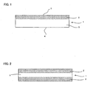
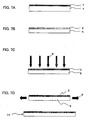
- FIG. 1 is a cross sectional view showing an example of a retardation film.
- a retardation reinforcing region 2 containing a refractive index anisotropic material is formed on one surface side of a polymer film 1.
- a concentration gradient of the refractive index anisotropic material in this case is high concentration on the surface 3 side, on which the retardation reinforcing region 2 is formed.
- the refractive index anisotropic material is not contained on the surface 4 side, on which the retardation reinforcing region 2 is not formed.
- the concentration gradient includes a case, as mentioned above, in which the refractive index anisotropic material is present in some region and is not present in other region as long as the concentrations are different in optional two points in the thickness direction.
- Such a retardation film preferably has the biaxial property and the retardation reinforcing region with the refractive index anisotropic material present is formed in the retardation film as mentioned above so that the retardation reinforcing region reinforces the function as the retardation layer, various optical functions can be provided based on the property of double refraction.
- TAC cellulose triacetate
- the above-mentioned retardation reinforcing region reinforces the function as the negative C plate and A plate. Therefore, such a retardation film has the functions as the negative C plate and A plate further reinforced with one film.
- the retardation reinforcing region can be formed easily, for example, only by coating the retardation reinforcing region forming coating solution, in which the above-mentioned refractive index anisotropic material is dissolved or dispersed, infiltrating the refractive index anisotropic material into the surface of the polymer film so as to be filled in the polymer film, and orienting the same at any point in time. Therefore, by changing the amount or the concentration of the above-mentioned coating solution, the retardation value of the retardation film mainly in the thickness direction and furthermore in the in-plane direction can be changed easily.
- the retardation value of the retardation film mainly in the in-plane direction and furthermore in the thickness direction can easily be changed. Therefore, the retardation value in the thickness direction and the in-plane direction can be realized in a range which has not conventionally been obtained, and even when a compensating plate having various kinds of retardation values is needed in a small lot, or the like, a retardation film can be obtained easily at a low cost, and thus it is advantageous.
- the retardation film unlike with the conventional ones produced by laminating a retardation layer as another layer on a base material so as to be laminated and formed, since the retardation reinforcing region filled with the refractive index anisotropic material and the base material region without being filled therewith are formed in the retardation film, the conventional problem of the peeling off of the retardation layer can be prevented, the reliability in terms of the heat resistance, the water resistance (durability in term of the delamination with respect to repetition of the coldness and the heat in the use environment or contact with water), or the like can be improved so as to be used stably.
- the alkaline resistance can be improved, it can endure the saponification process at the time of for example adhering to a polarizing layer. Moreover, since the excellent reworking property (repeated usability) is provided, a good yield is provided in the process, and thus it is advantageous.
- a polymer film used in the present invention is not particularly limited. In general, those made of a resin capable of transmitting a light in the visible light range is used preferably.
- an average light transmittance in the visible light range of 380 to 780 nm is 50% or more, preferably 70% or more, and particularly preferably 85% or more.
- an ultraviolet-visible spectrophotometer for example, UV-3100PC manufactured by Shimadzu Corporation
- the polymer film used in the present invention those having the refractive index regularity are preferable. That is, as the polymer film used in the present invention, those having the in-plane direction retardation and/or the thickness direction retardation are preferable.
- the retardation film in the present invention performs the function as an optical functional film such as an optical compensating plate, by obtaining a larger retardation value, for the following reasons. That is, it is assumed that, when the refractive index anisotropic material is filled in the polymer film, the filled refractive index anisotropic material reinforces the refractive index regularity, such as the property of double refraction, inherent to the polymer film, and thereby, a retardation film having various characteristics can be obtained.
- the polymer film used in the present invention those having some kind of refractive index regularity are used preferably.
- the refractive index regularity of the polymer film may be provided preliminarily before filling the polymer film with the refractive index anisotropic material, or it may be provided by orienting or the like after filling.
- the refractive index regularity in the present invention is that, for example, (1) the polymer film acts as the negative C plate, (2) the oriented polymer film has the characteristics of a negative C plate, a positive C plate, an A plate, or a biaxial plate, or the like.
- the polymer film has high swelling degree to predetermined solvents. That is because the above-mentioned refractive index anisotropic material is infiltrated and filled in the polymer film by coating the retardation reinforcing region forming coating solution, in which the refractive index anisotropic material is dissolved or dispersed in a solvent, onto the surface of the polymer film and swelling by the solvent. Specifically, it is preferable that the polymer film is swelled when the polymer film is soaked in a certain solvent. This phenomenon can be judged visually. For example, the swelling property to a solvent can be checked by forming a polymer film (film thickness: several ⁇ m), dropping a solvent thereon, and observing the infiltration condition of the solvent.
- the polymer film of the present invention may be a flexible material with the flexibility or a rigid material without the flexibility. It is preferable to use the flexible material since the material allows using the roll-to-roll process in the retardation film producing process, and thereby a retardation film excellent in productivity can be obtained.
- the cellulose based resin and the norbornene based polymer can be suitably used.
- cycloolefin polymer COP
- cycloolefin copolymer(COC) cycloolefin copolymer(COC)
- the cycloolefin polymer is preferably used since its low moisture absorbability and permeability enable the retardation film of the invention to be excellent in temporal stability of optical characteristics when the polymer film of the invention is constituted by the cycloolefin polymer.
- ARTON product name
- ZEONOR® product name manufactured by ZEON CORPORATION
- a cellulose ester is preferable.
- the cellulose esters the cellulose acylates are more preferable since they are commercially widely used and thus advantageous in its easy availability.
- lower fatty acid ester having 2 to 4 carbon atoms is preferable.
- a lower fatty acid ester such as a cellulose acetate which contains only a single lower fatty acid ester, or a lower fatty acid ester such as a cellulose acetate butilate or a cellulose acetate propionate which has a number of fatty acid esters may be exemplified.
- the cellulose acetate is particularly preferably used in the present invention.
- a cellulose triacetate with an average degree of acetification 57.5 to 62.5 % (degree of substitution: 2.6 to 3.0) is most preferably used.
- the degree of acetification denotes an amount of the bound acetic acid per cellulose unit mass. It can be measured and calculated from the degree of acetylization obtained by ASTM: D-817-91 (a testing method of the cellulose acetate or the like).
- the polymer film used in the present invention may be treated with the stretching process. This is because the stretching process may sometimes make the refractive index anisotropic material easy to be infiltrated in the polymer film.
- Such stretching process is not particularly limited to one kind and can be decided in accordance with the material constituting the polymer film or other members.
- a uniaxial stretching process and biaxial stretching process can be cited as examples of the stretching process.
- the configuration of the polymer film of the invention is not limited to a single layer configuration and may be a configuration with a number of layers laminated. In case it is the configuration with a number of layers laminated, the layers may be of the same composition or of different compositions.
- the film thickness of the polymer film used in the present invention is not particularly limited, and it can be selected optionally. Therefore, the film referred to in the present invention is not limited to the so-called film in a narrow sense but it includes also those having the film thickness in a range of the so-called sheets and plates. However, in general those having a relatively thin film thickness are used. As to the film thickness, those generally in a range of 10 ⁇ m to 200 ⁇ m, and in particular in a range of 20 ⁇ m to 100 ⁇ m can be used preferably.
- an oriented polymer film tends to be shrunk (orientation reversion) due to the heat applied at the time of the post process such as the lamination onto the polarizing layer during the retardation film producing process or before the producing process.
- the retardation value may be fluctuated according to the shrinkage.
- the temperature condition of the heating process is preferably a temperature from the glass transition temperature of the polymer film to the fusing temperature (or the melting point) thereof in general.
- the refractive index anisotropic material used in the present invention is not particularly limited as long as it is a material capable of filling the polymer film, and also, having a property of double refraction.
- a material having relatively small molecular weight is used because it is easily filled in the polymer film.
- a material having a molecular weight in a range of 200 to 1200, in particular, in a range of 400 to 800 is used.
- the molecular weight here refers to the molecular weight before polymerization for the below mentioned refractive index anisotropic material having a polymerizable functional group to be polymerized in the polymer film.
- the molecular structure of the material is in a shape of a rod. That is because the material in a shape of a rod can get into a gap in the polymer film relatively easily.
- the refractive index anisotropic material used in the present invention is a material having a liquid crystallinity (liquid crystalline molecules). If the refractive index anisotropic material is the liquid crystalline molecules, when the refractive index anisotropic material is filled in the polymer film, it can be in a liquid crystalline state in the polymer film so that the property of double refraction of the refractive index anisotropic material can be reflected to the retardation film more effectively.
- the refractive index anisotropic material a nematic liquid crystalline molecule material, a cholesteric liquid crystalline molecule material, a chiral nematic liquid crystalline molecular material, a smectic liquid crystalline molecule material, and a discotic liquid crystalline molecule material can be used.
- the refractive index anisotropic material is the nematic liquid crystalline molecule material.
- the refractive index anisotropic material is the nematic liquid crystalline molecule material.
- the refractive index anisotropy can be realized more certainly.
- the above-mentioned nematic liquid crystalline molecule is a molecule having spacers on both mesogen ends. Since the nematic liquid crystalline molecule having spacers on both mesogen ends has flexibility, white turbidity, when getting into the gap in the polymer film, can be prevented.
- the refractive index anisotropic material used in the present invention those having a polymerizable functional group in the molecule are used preferably.
- the refractive index anisotropic material can be polymerized (cross-linked) in the polymer film, after being filled in the polymer film, by the function of the radical generated from a photo-polymerization initiator due to a light irradiation, by the function of the electron beam or the like. Therefore, problems, such as exudation of the refractive index anisotropic material after being formed as the retardation film, can be prevented so that a retardation film which can be used stably can be provided.
- the "three-dimensionally cross-link” means a state that the liquid crystalline molecules are polymerized three dimensionally with each other so as to be a mesh (network) structure.
- the polymerizable functional group is not particularly limited, and various kinds of polymerizable functional groups to be polymerized by a function of the ionizing radiation such as the ultraviolet ray and the electron beam, or heat, can be used.
- a radical polymerizable functional group, a cationic functional group, or the like can be presented.
- a functional group having at least one ethylenically unsaturated double bond capable of addition polymerization can be presented.
- a vinyl group, an acrylate group (it is the general term including an acryloyl group, a methacryloyl group, an acryloyloxy group, and a methacryloyloxy group) or the like, with or without a substituent, can be presented.
- a cationic polymerizable functional group an epoxy group, or the like can be presented.
- an isocyanate group, an unsaturated triple bond, or the like can be presented.
- a functional group having an ethylenically unsaturated double bond can be used preferably.
- a liquid crystalline molecule whose molecular structure is in a shape of a rod, and having the above-mentioned polymerizable functional group on its end can be used particularly preferably.
- a nematic liquid crystalline molecule having polymerizable functional groups on both ends they can be polymerized with each other three-dimensionally so as to provide a mesh (network) structure state. Therefore, a stronger polymer film can be obtained.
- liquid crystalline molecule having an acrylate group on its end can be used preferably.
- the specific examples of the nematic liquid crystalline molecule having an acrylate group on its end will be shown by the below-mentioned chemical formulae (1) to (6).
- liquid crystalline molecules represented by the chemical formulae (1), (2), (5) and (6) can be prepared according to the methods disclosed in Makromol Chem. 190, 3201-3215 (1989) by D. J. Broer , et al. or Makromol Chem. 190, 2250 (1989) by D. J. Broer , et al., or a method similar thereto.
- preparation of the liquid crystalline molecules represented by the chemical formulae (3) and (4) is disclosed in DE 195,04,224 .
- nematic liquid crystalline molecules having an acrylate group on its end those represented by the below-mentioned chemical formulae (7) to (17) can also be presented.
- x is the inteaer of 2 to 5.
- the refractive index anistropic material may be used by two or more kinds.
- the refractive index anisotropic material includes a liquid crystalline molecule having one or more polymerizable functional group on the both ends with a molecular structure in a shape of a rod, and a liquid crystalline molecule having one or more polymerizable functional group on one end with a molecular structure in a shape of a rod
- the polymerization density (cross linking density) and the retardation function can be adjusted preferably according to the adjustment of the composition ratio thereof, and thus it is preferable.
- a rod like liquid crystalline molecule having one or more polymerizable functional group on one end can easily be infiltrated in the polymer film and/or oriented in the polymer film, the retardation function can easily be reinforced.
- the polymerization density can be made higher by the rod like liquid crystalline molecule having one or more polymerizable functional group on the both ends, the endurance such as the molecule exudation preventing property, the solvent resistance and the heat resistance can be provided.
- the refractive index anisotropic material used in the present invention in terms of further reinforcing the retardation function and improving the film reliability, it is preferable to use a liquid crystalline molecule having a rod like molecular structure and having the polymerizable functional group, and a liquid crystalline molecule having a rod like molecular structure and having no polymerizable functional group.
- a liquid crystalline molecule having a rod like molecular structure and having one or more of the polymerizable functional groups on the both ends a liquid crystalline molecule having a rod like molecular structure and having one or more of the above-mentioned polymerizable functional groups on one end and a liquid crystalline molecule having a rod like molecular structure and having no polymerizable functional groups on the both ends. Since the rod like liquid crystalline molecule having no polymerizable functional group can easily be infiltrated in the polymer film and/or oriented in the polymer film, the retardation function can further be reinforced.
- the endurance such as the molecule exudation preventing property, the solvent resistance and the heat resistance can be provided.
- the above-mentioned refractive index anisotropic material is characterized in that it has a concentration gradient in the thickness direction of the above-mentioned polymer film.
- the concentration gradient of the refractive index anisotropic material is high concentration on one surface side of the polymer film, and becomes low concentration toward the other surface side
- the concentration gradient of the refractive index anisotropic material may be high concentration on the both surface sides of the polymer film, and becomes low concentration toward the central part, or the concentration gradient of the refractive index anisotropic material may be low concentration on surface side and may have a high concentration region in the polymer film.
- the first embodiment of the present invention is an embodiment that the concentration gradient of the refractive index anisotropic material is high concentration on one surface side of the polymer film, and becomes low concentration toward the other surface side.
- the first embodiment is shown schematically in Fig. 1 .
- a retardation reinforcing region 2 containing the refractive index anisotropic material is formed on one surface side 3 of a polymer film 1.
- a base material region 5 is formed on the other surface side 4 of the opposite side.
- the retardation reinforcing region is produced by containing or infiltrating the refractive index anisotropic material in the polymer film.
- the state of the polymer film molecules and the refractive index anisotropic material molecules in the retardation reinforcing region is not yet revealed sufficiently, especially in the case of producing by infiltrating a refractive index anisotropic material made of rod like molecules having the electric dipole moment in the longer axis direction thereof from the surface of the polymer film made of a linear polymer, it is assumed to be in the following state.
- the linear polymers in the polymer film are disposed substantially in the plane parallel to the front and rear surfaces of the polymer film on the average (however, the distribution of the direction thereof in the parallel planes is in disorder).
- the rod like refractive index anisotropic material molecules infiltrated from the surface of the polymer film have the orientation forcibly aligned by the polymer film arrangement so as to be arranged in the plane parallel to the front and rear surfaced of the polymer film on the average (however, the distribution of the direction thereof in the parallel planes is in disorder).
- the refractive index in the normal direction orthogonal to the plane parallel to the front and rear surfaces of the polymer film becomes relatively lower than the refractive index in the plane direction.
- the retardation film in this state By further orienting the retardation film in this state in for example a specific direction in the plane parallel to the front and rear surfaces of the polymer film, since the electric dipole moment vectors of the rod like refractive index anisotropic material are oriented in the specific direction on the average, the refractive index in the specific direction is further made higher. Thereby, a positive A plate characteristic is provided in addition to the negative C plate characteristic.
- the refractive index anisotropic material has a plurality of polymerizable functional groups per one molecule and they are polymerized and fixed, in the retardation reinforcing region, the molecular chains of the polymer film are enveloped by the three-dimensionally cross-linked molecules of the refractive index anisotropic material so as to be in a state with the molecular chains of the polymer film inserted in the mesh of the three-dimensionally cross-linked molecules of the refractive index anisotropic material.
- the molecules of the polymer film and the molecules of the refractive index anisotropic material can be chemically bonded with each other, it comes into a composite polymer state with the molecules of the polymer film and the molecules of the refractive index anisotropic material cross-linked three-dimensionally.
- the retardation reinforcing region containing the refractive index anisotropic material is formed on one surface side of the polymer film as mentioned above.
- the concentration gradient of the refractive index anisotropic material in the retardation reinforcing region is generally made higher concentration on the surface side of the polymer film, and is made lower concentration toward the center side in the thickness direction of the polymer film.
- the base material region, which contains no refractive index anisotropic material is formed on the other surface side of the polymer film.
- the retardation reinforcing region is formed on one surface side of the polymer film as mentioned above, the following advantages can be obtained.
- the refractive index anisotropic material is not contained on the base material region side, the nature of the polymer film remains as it is. Since the base material region not containing the refractive index anisotropic material is provided, there are advantages such as, for example, when the adhesive property of the polymer film itself is good or the like, a polarizing film can easily be obtained by laminating a polarizing layer on the above-mentioned base material region side. Moreover, the strength of the retardation reinforcing region containing the refractive index anisotropic material may be deteriorated in some cases. However, since the base material region is provided, the strength as the retardation film can be maintained, and thus, it is advantageous.
- the thickness of the retardation reinforcing region in the present invention is generally in a range of 0.5 ⁇ m to 8 ⁇ m, and it is particularly preferably in a range of 1 ⁇ m to 4 ⁇ m. When it is smaller than the above-mentioned range, a sufficient retardation value cannot be obtained. Furthermore, it is difficult to increase the thickness more than the above-mentioned range.
- the concentration gradient of the refractive index anisotropic material is as this embodiment, can be judged by the composition analysis of the retardation reinforcing region and the base material region.
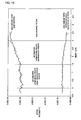
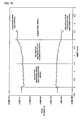
- composition analyzing method a method of measuring the concentration distribution of the material in the thickness direction by cutting a retardation film by the GSP (Gradient Shaving Preparation) so as to provide the cross section in the thickness direction, and carrying out the Time of Flight Secondary Ion Mass Spectrometry (TOF-SIMS), or the like can be presented.
- GSP Gradient Shaving Preparation
- the Time of Flight Secondary Ion Mass Spectrometry can be carried out, for example, by measuring the positive and/or negative secondary ions in the cross section in the retardation film thickness direction with TFS-2000 manufactured by Physical Electronics Corp. as the Time of Flight Secondary Ion Mass Spectrometer, Ga + as the primary ion species, 25 kV as the primary ion energy and 5 kV post acceleration.
- TFS-2000 manufactured by Physical Electronics Corp.
- Ga + as the primary ion species
- 25 kV the primary ion energy
- 5 kV post acceleration the thickness direction concentration distribution of the refractive index anisotropic material can be obtained by plotting the secondary ion intensity derived from the refractive index anisotropic material against the thickness direction.
- the relative concentration change of the refractive index anisotropic material and the base material film can be observed.
- the secondary ion derived from the refractive index anisotropic material for example, the total sum of the secondary ion observed relatively strongly at the surface or the part with the refractive index anisotropic material presumed to be filled by the analysis method such as the cross section TEM observation can be used.
- the secondary ion derived from the base material film for example, the total sum of the secondary ion observed relatively strongly at the surface or the part with the refractive index anisotropic material presumed not to be filled by the analysis method such as the cross section TEM observation can be used.
- the contact angles of the above-mentioned retardation film with respect to pure water are different between one surface and the other surface.
- a polarizing film by for example directly laminating a hydrophilic resin based polarizing layer having a PVA base material onto the retardation film, if the polarizing layer is laminated on the surface having a lower contact angle, a polarizing film can be obtained without inhibiting the adhesion even in the case a water based adhesive is used.
- the difference of the contact angles of one surface and the other surface of the retardation film with respect to pure water is preferably 2 degrees or more, more preferably 4 degrees or more and particularly preferably 5 degrees or more.
- the first embodiment includes also an embodiment with the refractive index anisotropic material contained by a high concentration on one surface side of the polymer film and the refractive index anisotropic material contained by a low concentration on the opposite surface side. Also in this case, there is an advantage that the low concentration side is close to the nature of the polymer film itself in terms of the surface adhesion property and the strength compared with the high concentration side.
- the concentration of the refractive index anisotropic material is preferably a low concentration within a range not to disturb the adhesion property of the polymer film itself, for example, a concentration to provide the difference of the contact angles between the high concentration surface and the low concentration surface of the retardation film with respect to pure water of 2 degrees or more, more preferably 4 degrees or more and particularly preferably 5 degrees or more.
- the concentration gradient of the material having refractive index anisotropy in a thickness direction of the polymer film varies continuously.
- the peeling strength can be made higher so that the reliability such as the heat resistance and the water resistance (durability in term of the delamination with respect to repetition of the coldness and the heat in the use environment or contact with water), the alkaline resistance, and the reworking property, or the like can be improved.
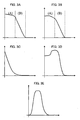
- the continuous change of the concentration gradient here denotes the case where the concentration change in the thickness direction is continuous in the case the concentration is plotted in the vertical axis and the thickness direction is plotted in the lateral axis as for example shown in FIGS. 3A to 3E .
- a region in which the concentration gradient of the material having refractive index anisotropy is gentle and a region in which the concentration gradient of the material having refractive index anisotropy is steep are provided.
- a sufficient retardation value can be ensured, and furthermore, by linking continuously the concentrations from the high concentration region to the low concentration region in the steep concentration gradient region, the stress concentration to a specific interface in the film can be prevented, and thus the reliability can be improved while providing a desired retardation.
- “gentle” or “steep” in the concentration gradient denotes the relative relationship in the concentration gradient in the thickness direction of the material having refractive index anisotropy.
- the region having a gentle concentration gradient and the region having a steep concentration gradient are relatively classified macroscopically as a region having the concentration gradient continuously in a small value and a region having the same continuously in a large value.
- the region having the gentle concentration gradient in this case includes a region having a constant concentration gradient.
- the region having a gentle concentration gradient includes the case having a relatively high concentration of the refractive index anisotropic material with the refractive index anisotropic material filled in the polymer film by a concentration close to the saturated state as shown in the region A of FIG.
- the region having a steep concentration gradient includes the region of the transition from a region containing the refractive index anisotropic material in a relatively high concentration to the base material region containing no refractive index anisotropic material as shown in the region B of FIG. 3A and the region B of FIG. 3B , or the like.
- the concentration gradient as shown in FIG. 3A and FIG. 3B is preferable.
- a high retardation value is not particularly required, as shown in FIG.
- an embodiment which a region having a steep concentration gradient transiting from a high concentration to a low concentration toward the central part formed in the vicinity of the polymer film surface with the refractive index anisotropic material filled in a high concentration, and a region having a gentle concentration gradient with the refractive index anisotropic material filled in a low concentration formed on the central part are provided continuously may be employed.
- the continuous change of the concentration gradient of the material having refractive index anisotropy in the thickness direction of the polymer film and the presence of the above-mentioned region having a gentle concentration gradient of the material having refractive index anisotropy and the above-mentioned region having steep concentration gradient of the material having refractive index anisotropy can be judged by the concentration distribution analysis of the cross section in the retardation film thickness direction explained above with use of the Time of Flight Secondary Ion Mass Spectrometry (TOF-SIMS) or the like.
- TOF-SIMS Time of Flight Secondary Ion Mass Spectrometry
- the biaxial property in the present invention denotes the optically biaxial property, which is n 1 ⁇ n 2 ⁇ n 3 with the premise that the principal refractive indices of the optically anisotropic medium are n 1 , n 2 , n 3 (the principal axes coordinate system of the index ellipsoid of the optically anisotropic medium are X 1 , X 2 , X 3 ). That is, those can be represented by n 1 > n 2 > n 3 in the case of representing the principal refractive indices of the optically anisotropic medium as n 1 , n 2 , n 3 in order of size.
- the principal refractive indices n 1 , n 2 , n 3 are the refractive indices in the principal axes direction (X 1 axis direction, X 2 axis direction, X 3 axis direction) in the index ellipsoid. In other words, they correspond to the radiuses in the principal axes direction of the index ellipsoid respectively.
- the biaxial retardation film has refractive indices satisfying the condition of n 1 > n 2 > n 3 , wherein the principal refractive indices of the index ellipsoid are n 1 , n 2 , n 3 in order of size when defining the index ellipsoid of the retardation film.
- those having the principal refractive indices directions of the retardation film coinciding with the in-plane direction of the retardation film (direction parallel to the front and rear surfaces of the retardation film) and the film thickness direction (normal direction of the front and rear surfaces of the retardation film) are representative.
- the principal axes directions of the index ellipsoid of the retardation film (X 1 axis direction, X 2 axis direction, and the X 3 axis direction) provide a three dimensional coordinate system including the X axis (this is in the slow axis direction) and the Y axis (this is the fast axis direction) provided in the plane of the retardation film and the Z direction provided in the direction orthogonal to the retardation film plane.
- nx > ny > nz, nz > nx > ny and nx > nz > ny can be presented, in which nx is the refractive index along the slow axis in the in-plane direction of the film, ny is the refractive index along the fast axis in the in-plane direction of the film, and nz is the refractive index along the thickness direction of the film.
- the slow axis direction denotes the direction to have the largest refractive index in the film plane and the fast axis direction denotes the direction to have the smallest refractive index in the film plane.
- nx > ny > nz is preferable, in which nx is the refractive index along the slow axis in the in-plane direction of the film, ny is the refractive index along the fast axis in the in-plane direction of the film, and nz is the refractive index along the thickness direction of the film.
- a retardation film having the optical characteristics of both a positive A plate and a negative C plate can be obtained.
- a positive A plate and a negative C plate need not be provided as the compensation layer so that it can be used preferably for a liquid crystal display having a liquid crystal layer of a VA mode, an OCB mode, or the like.
- the retardation layer is classified according to the optical axis direction and the size of the refractive index in the optical axis direction with respect to the refractive index in the direction orthogonal to the optical axis.
- One having the optical axis direction along the plane of the retardation layer is referred to as an A plate
- one having the optical axis direction oriented in the normal direction perpendicular to the retardation layer is referred to as a C plate
- one having the optical axis direction inclined with respect to the normal direction is referred to as an O plate.
- a positive plate those having a refractive index in the optical axis direction larger than the refractive index in the direction orthogonal to the optical axis are referred to as a positive plate
- those having a refractive index in the optical axis direction smaller than the refractive index in the direction orthogonal to the optical axis are referred to as a negative plate.
- the direction of the principal refractive indices of the retardation film may be inclined with respect to the in-plane direction and the thickness direction of the above-mentioned film.
- the inclination embodiment is not particularly limited.
- an embodiment having the n 2 direction in the Y axis in the retardation film plane, the n 1 direction in the direction of rotating X axis in the retardation film plane by ⁇ around the Y axis as the rotation axis, and the n 3 direction in the direction of rotating the Z axis provided in the direction orthogonal to the retardation film plane by ⁇ around the Y axis as the rotation axis can be presented.
- an embodiment having the n 1 direction in the X axis in the retardation film plane, the n 2 direction in the direction of rotating the Y axis in the retardation film plane by ⁇ around the X axis as the rotation axis, and the n 3 direction in the direction of rotating the Z axis provided in the direction orthogonal to the retardation film plane by ⁇ around the X axis as the rotation axis, or the like can be presented.
- the principal refractive indices direction of the retardation film is inclined with respect to the in-plane direction and the thickness direction of the film, the improvement of the visual angle can be obtained corresponding to various applications and design demands.
- the principal refractive indices of the retardation film may be provided preferably in the direction inclined with respect to the in-plane direction and the thickness direction of the retardation film.
- nx > ny > nz is preferable, in which nx is the refractive index along the slow axis in the in-plane direction of the film, ny is the refractive index along the fast axis in the in-plane direction of the film, and nz is the refractive index along the thickness direction of the film.
- a retardation film having the optical characteristics as a combination of those of the A plate and the negative C plate can be obtained.
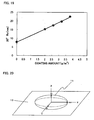
- the above-mentioned refractive indices nx, ny, nz can be found by the three-dimensional refractive indices measurement at a 589 nm wavelength under the 23°C, 55% RH environment using for example an automatic birefringence measuring apparatus (for example, product name: KOBRA-21ADH, produced by Oji Scientific Instruments), either in the case of the embodiment having the principal refraction indices direction of the retardation film coinciding with the in-plane direction and the thickness direction of the film or in the case of the embodiment having the same inclined.
- an automatic birefringence measuring apparatus for example, product name: KOBRA-21ADH, produced by Oji Scientific Instruments
- nx > ny > nz can be obtained by orienting in one direction in the in-plane direction of the polymer film or orienting in two directions orthogonal with each other in the in-plane direction of the polymer film by different magnifications.
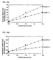
- the thickness direction and in-plane direction retardation values to be obtained are adjusted by changing the retardation reinforcing region, and the stretching direction, the stretching ratio, or the like, the range of the thickness direction and in-plane direction retardation values to be obtained can be enlarged.
- the thickness direction retardation is 100 to 300 nm, and the in-plane direction retardation is 10 to 150 nm. In this case, for example the visual angle improving effect can be improved.
- the thickness direction retardation is 150 to 300 mm and the in-plane direction retardation is 40 to 100 nm.
- the above-mentioned thickness direction and in-plane direction retardation values can be obtained by finding the refractive indices nx, ny, nz by the three-dimensional refractive indices measurement at a 589 nm wavelength under the 23°C, 55% RH environment using for example an automatic birefringence measuring apparatus (for example, product name: KOBRA-21ADH, produced by Oji Scientific Instruments).
- an automatic birefringence measuring apparatus for example, product name: KOBRA-21ADH, produced by Oji Scientific Instruments.
- the thickness direction and in-plane direction retardation values to be obtained are adjusted using the both means for the retardation reinforcing region and the orientation, a desired retardation value can be achieved even with a smaller stretching ratio than that of adjusting the retardation value only by the orientation.
- the retardation film is cloudy so that the retardation film has higher haze value and higher depolarization. That is, a problem is involved in that the polarization cannot be controlled due to the disturbance of the polarization state.
- the depolarization can be made extremely small.
- a retardation film with 10 to 150 nm in-plane direction retardation, a haze value of 1% or less measured in accordance with JIS-K7136 (established in 2000), or JIS-K7105 (established in 1981), and furthermore, with 40 to 100 nm in-plane direction retardation, a haze value of 0.8% or less measured in accordance with JIS-K7136 or JIS-K7105 can be achieved.
- the retardation value, in the visible light range, of the retardation film on the shorter wavelength side is larger than that of the longer wavelength side.
- the retardation value of a liquid crystal material used for a liquid crystal layer of a liquid crystal display, in the visible light range, on the shorter wavelength side is larger than that of the longer wavelength side. Therefore, in the case of using the above-mentioned retardation film as, for example, an optical compensating plate, there is an advantage that the compensation can be carried out in the all wavelength range in the visible light range.
- the retardation value in the visible light range of the retardation film In order to make the retardation value in the visible light range of the retardation film larger on the shorter wavelength side than that of the longer wavelength side, it is preferable to select, for the polymer film and the refractive index anisotropic material, those having larger retardation value, in the visible light range, on the shorter wavelength side than that of the longer wavelength side.
- the TAC film, used for the protecting film of the polarizing layer such as a polyvinyl alcohol (PVA)
- PVA polyvinyl alcohol
- the retardation value, in the visible light range, of the retardation film on the longer wavelength side may be larger than that of the shorter wavelength side.
- the retardation film of the present invention when used as, for example, a polarizing plate in a state laminated on a polarizing film, it is advantageous in that the excellent light leakage compensation can be provided, and thus it is preferable.
- such a retardation film containing at least the refractive index anisotropic material in the polymer film may contain another component as long as the desired effect is not deteriorated.
- a residual solvent, a photo polymerization initiating agent, a polymerization inhibiting agent, a leveling agent, a chiral agent, a silane coupling agent, or the like may be contained.
- said retardation film may further have other layers laminated directly.
- another retardation layer may further be laminated directly on the retardation film.
- other optical functional layers for example, a polarizing layer may be laminated directly.
- Said retardation film includes an embodiment in which the refractive index anisotropic material remains in a film state on the polymer film surface of the infiltration side in the case it is formed by coating the retardation reinforcing region forming coating solution prepared by dissolving or dispersing the refractive index anisotropic material in a solvent onto the surface of a polymer film for infiltrating the refractive index anisotropic material in the polymer film.
- the retardation film capable being rolled into a cylindrical form having minimum diameter of 6 inches or less is formed into a long continuous film (also referred to as a web) and is rolled on a cylinder so as to be in a form of roll at the time of storage other than production, inspection and post process, and standby for a process, in order to improve the mass productivity and the production yield at the time of the production, the storage, the transportation and the post process.
- the diameter of the tube to be the core of the roll is in general 6 inches or less, an in some cases 3 inches.
- the retardation film is capable of being rolled into a cylindrical form having a minimum diameter of 6 inches or less, more preferably a minimum diameter of 3 inches or less.
- a material having refractive index anisotropy in general tends to be hard and brittle. Particularly in the case of polymerization for fixation, the tendency is remarkable. Therefore, according to the conventional retardation film having a configuration of laminating a retardation layer as another layer onto a polymer film base material, due to the hard and brittle retardation layer, a problem is involved in that the retardation layer is cracked or the retardation layer is peeled off from the base material at the time of rolling up into a diameter of 6 inches or less. For the cracking prevention, a protection layer needs to be further provided on the retardation layer.
- the problem can be solved by producing, storing, or the like the retardation film in a sheet like state of for example a 30 cm square sheet, the production efficiency and the mass productivity are deteriorated.
- the retardation film obtained in the present invention has a retardation reinforcing region containing the refractive index anisotropic material formed in the polymer film, the retardation layer (retardation reinforcing region) is contained inside the polymer film, and a region not containing the retardation layer (or containing only little amount) is also provided. Therefore, without the need of providing a protection layer, or the like, cracking can hardly be generated by the stress concentration at the time of rolling into a cylindrical form so that a form of roll can be provided preferably.
- said retardation film may be used not only by one sheet of a single layer but also by an embodiment of sticking and laminating two or more sheets if necessary.
- laminating two or more sheets an embodiment of laminating two or more of the same retardation films with the principal refractive indices directions (optical anisotropy directions) aligned, an embodiment of laminating two or more of the same retardation films with the principal refractive indices directions differing with each other, an embodiment of laminating two or more of retardation films having different optical anisotropies with the principal refractive indices directions (optical anisotropy directions) aligned, an embodiment of laminating two or more of retardation films having different optical anisotropies with the principal refractive indices directions (optical anisotropy directions) differing with each other, or the like can be presented. In these cases, a large optical anisotropic value not to be realized by only one film can be realized, or a complicated optical anisotropy
- Adhesion and lamination of the retardation films can be executed by for example adhering via an appropriate transparent adhesion layer.
- the above-mentioned retardation film can be used for various applications as the optical functional film.
- an optical compensating plate for example, a visual angle compensating plate
- an elliptical polarization plate for example, a polarization plate
- a brightness improving plate and the like can be presented.
- the application as the optical compensating plate is particularly preferable. Specifically, it can be used for the application as a biaxial optical compensating plate having the functions of both a negative C plate and a positive A plate by using a TAC film as the polymer film, using a liquid crystalline compound, whose molecular structure is in a shape of a rod, as the refractive index anisotropic material and orienting the film at any point in time.
- said retardation film can be used as various optical functional films used for a display device.
- the retardation film when used as an optical compensating plate having the functions of a negative C plate and a positive A plate as mentioned above, it can be used preferably for a liquid crystal display having a VA mode, OCB mode or the like liquid crystal layer.
- a method for producing a retardation film in the present invention comprises:
- a fixing process of fixing the refractive index anisotropic material infiltrated in the polymer film is provided after the above-mentioned drying process.
- fixation By the fixation, exudation of the refractive index anisotropic material from the surface after the production can be prevented so that the retardation film stability can be improved.
- fixation can be carried out by the polymerization after infiltration of the refractive index anisotropic material into the polymer film so as to provide a polymer.
- “after the process” denotes a timing after the same without limitation, and includes not only "a timing immediately thereafter” but also "a timing after another process”.
- FIGS. 6A to 6D are process diagrams showing an example of the method for producing a retardation film of the present invention.
- a coating process of coating a retardation reinforcing region forming coating solution 7 onto a polymer film 1, is carried out.
- an infiltration process of infiltrating the refractive index anisotropic material in the retardation reinforcing region forming coating solution into the polymer film, and a drying process, of drying the solvent in retardation reinforcing region forming coating solution coated in the coating process, are carried out.
- the refractive index anisotropic material in the retardation reinforcing region forming coating solution is infiltrated from the polymer film surface so that a retardation reinforcing region 2, containing the refractive index anisotropic material on the polymer film surface side, is formed. Accordingly, the retardation reinforcing region 2, which contains the refractive index anisotropic material, and the base material region 5, which contains no refractive index anisotropic material, are formed in the polymer film. Then, as shown in FIG. 6C , an orientation process of orienting 8 the polymer film is carried out. Then, finally, as shown in FIG.
- a retardation film 10 is formed by carrying out a fixing process of polymerizing the refractive index anisotropic material contained in the polymer film by the function of the photo polymerization initiator by irradiating an ultraviolet ray 9 from the retardation reinforcing region 2 side.
- the in-plane direction retardation of the retardation film can be enlarged in the orientation process.
- FIGS. 7A to 7D are process diagrams showing another example of the method for producing a retardation film of the present invention.
- a coating process of coating a retardation reinforcing region forming coating solution 7 onto a polymer film 1, is carried out.
- an infiltration process of infiltrating the refractive index anisotropic material in the retardation reinforcing region forming coating solution into the polymer film surface, is carried out.
- a drying process of drying the solvent in the retardation reinforcing region forming coating solution coated in the coating process, is carried out.
- the refractive index anisotropic material in the retardation reinforcing region forming coating solution is infiltrated from the polymer film surface so that a retardation reinforcing region 2, containing the refractive index anisotropic material on the polymer film surface side, is formed. Accordingly, the retardation reinforcing region 2, which contains the refractive index anisotropic material, and the base material region 5, which contains no refractive index anisotropic material, are formed in the polymer film. Then, as shown in FIG.
- a fixing process of polymerizing the refractive index anisotropic material contained in the polymer film by the function of the photo polymerization initiator is carried out by irradiating an ultraviolet ray 9 from the retardation reinforcing region 2 side.
- a retardation film 10 is formed by carrying out an orientation process of orienting 8 the polymer film.
- FIGS. 8A to 8D are process diagrams showing a general example of a method for producing a retardation film.
- an orientation process of orienting 8 a polymer film 1 is carried out.
- a coating process of coating a retardation reinforcing region forming coating solution 7 onto the oriented polymer film 1, is carried out.
- an infiltration process of infiltrating the refractive index anisotropic material in the retardation reinforcing region forming coating solution into the polymer film surface, is carried out.
- a drying process of drying the solvent in the retardation reinforcing region forming coating solution coated in the coating process, is carried out.
- the refractive index anisotropic material in the retardation reinforcing region forming coating solution is infiltrated from the polymer film surface so that a retardation reinforcing region 2, containing the refractive index anisotropic material on the polymer film surface side, is formed.
- the retardation reinforcing region 2, which contains the refractive index anisotropic material, and the base material region 5, which contains no refractive index anisotropic material are formed in the polymer film.
- a retardation film 10 is formed by carrying out a fixing process of polymerizing the refractive index anisotropic material contained in the polymer film by the function of the photo polymerization initiator by irradiating an ultraviolet ray 9 from the retardation reinforcing region 2 side.
- a biaxial retardation film can be formed easily by coating the above-mentioned retardation reinforcing region forming coating solution and orienting the infiltrated polymer film at any point in time. Furthermore, only by changing the coating amount, or the like of the retardation reinforcing region forming coating solution, the retardation value mainly in the thickness direction and furthermore in the in-plane direction of the retardation film to be obtained can be changed, and only by changing the stretching direction, the stretching ratio, or the like, the retardation value mainly in the in-plane direction and furthermore in the thickness direction of the retardation film to be obtained can be changed.
- the range of the thickness direction and in-plane direction retardation values can be enlarged, and there is an advantage that a biaxial retardation film having optional thickness direction and in-plane direction retardation values can be obtained easily even for a small amount.
- Each process may be carried out two or more times. For example, first a coating process, of coating a first retardation reinforcing region forming coating solution on a polymer film is carried out. Then, an infiltration process, of infiltrating a first refractive index anisotropic material in the first retardation reinforcing region forming coating solution into the polymer film, and a drying process, of drying the solvent in the first retardation reinforcing region forming coating solution, are carried out.
- a retardation film may be formed by further carrying out a coating process, of coating a second retardation reinforcing region forming coating solution onto the surface on the side with the first retardation reinforcing region forming coating solution coated, and subsequently, an infiltration process, of infiltrating a second refractive index anisotropic material in the second retardation reinforcing region forming coating solution into the polymer film, and a drying process, of drying the solvent in the second retardation reinforcing region forming coating solution, a fixing process from the side with the second retardation reinforcing region forming coating solution coated, and furthermore, an orientation process.
- a rod like liquid crystalline molecule having no polymerizable functional group to be easily infiltrated into the polymer film is used as the first refractive index anisotropic material and a rod like liquid crystalline molecule having a polymerizable functional group is used as the second refractive index anisotropic material, a region containing a rod like liquid crystalline molecule having no polymerizable functional group capable of reinforcing the retardation and a region containing a rod like liquid crystalline molecule having the polymerizable functional group on the surface side are formed at the same time so that the effect of stabilizing can be obtained by the polymerization by the fixing process of the polymer film surface while having the further reinforced retardation.
- a process of further coating a coating solution prepared by dissolving or dispersing a material having a polymerizable functional group, other than the refractive index anisotropic material, in a solvent, a process of drying the coating solution, and furthermore a process of polymerizing the polymerizable functional group may be provided after the above-mentioned coating process of coating the retardation reinforcing region forming coating solution, the above-mentioned infiltrating process and the above-mentioned drying process of the present invention.
- the heating process temperature condition is preferably a temperature from the glass transition temperature of the polymer film to the fusing temperature (or the melting point) in general.
- the coating process in the present invention is a process of coating a retardation reinforcing region forming coating solution, in which a refractive index anisotropic material is dissolved or dispersed in a solvent, on at least one surface side of a polymer film.
- the retardation value of the obtained retardation film can be changed by the coating amount of the retardation reinforcing region forming coating solution in the coating process.
- the retardation reinforcing region forming coating solution used in the present invention contains at least a solvent and a refractive index anisotropic material dissolved or dispersed in the above-mentioned solvent. According to a needed, other additives may be added. As such additives, specifically, when the used refractive index anisotropic material is a photo-curing type, a photo-polymerization initiator or the like can be presented. Additionally, a polymerization inhibitor, a leveling agent, a chiral agent, a silane coupling agent or the like can be presented.
- the refractive index anisotropic material used for the retardation reinforcing region forming coating solution is same as those described in the above-mentioned column of "A. Retardation film", explanation is omitted here.
- the refractive index anisotropic material has a polymerizable functional group and the below-mentioned fixing process (process of polymerizing the refractive index anisotropic material) is carried out in the producing process for the retardation film, since the refractive index anisotropic material contained in the retardation film is polymerized by a predetermined polymerization degree, strictly speaking, it is different from that used for the retardation reinforcing region forming coating solution.
- the solvent used for the above-mentioned retardation reinforcing region forming coating solution is not particularly limited as long as it is a solvent capable of sufficiently swelling the polymer film and capable of dissolving or dispersing the refractive index anisotropic material.
- a cyclohexanone can be used preferably.
- the concentration of the refractive index anisotropic material in the solvent, in the retardation reinforcing region forming coating solution of the present invention is not particularly limited, it is generally in a range of 5% by mass to 40% by mass, and particularly preferably in a range of 15% by mass to 30% by mass.
- the coating amount onto the polymer film differs depending on the retardation value required for the obtained retardation film, it is preferable that the coating amount of the refractive index anisotropic material after the drying operation is in a range of 0.8 g/m 2 to 6 g/m 2 , and particularly preferably in a range of 1.6 g/m 2 to 5 g/m 2 .
- the coating method in this process is not particularly limited as long as it is a method capable of coating the retardation reinforcing region forming coating solution evenly onto the polymer film surface, and a method such as bar coating, blade coating, spin coating, die coating, slit reverse, roll coating, dip coating, ink jet method, micro gravure method and the like can be used.
- a method such as bar coating, blade coating, spin coating, die coating, slit reverse, roll coating, dip coating, ink jet method, micro gravure method and the like can be used.
- an infiltration process of infiltrating the refractive index anisotropic material, contained in the retardation reinforcing region forming coating solution coated in the coating process, into the polymer film; and a drying process of drying the solvent contained in the retardation reinforcing region forming coating solution coated in the coating process, are carried out.
- the infiltration process which is a process of leaving the polymer film after coating so that the refractive index anisotropic material is sufficiently infiltrated and taken into the polymer film, may be carried out simultaneously with the drying process depending on the kind of the solvent to be used or the like.
- the infiltration process it is preferable that 90% by mass or more, preferably 95% by mass or more, particularly preferably 100% by mass of the refractive index anisotropic material in the above-mentioned retardation reinforcing region forming coating solution is infiltrated and taken into the polymer film.
- 90% by mass or more, preferably 95% by mass or more, particularly preferably 100% by mass of the refractive index anisotropic material in the above-mentioned retardation reinforcing region forming coating solution is infiltrated and taken into the polymer film.
- the surface is cloudy so that the light transmittance of the film may be lowered.
- the polymer film after the infiltration and drying processes have the haze value measured in accordance with JIS-K7136 of the surface on the infiltration side of 10% or less, more preferably 2% or less, and particularly preferably 1% or less.
- the temperature and the time may differ drastically depending on the kind of the solvent to be used and whether or not it is carried out simultaneously with the infiltration process.
- the drying process is carried out at a temperature generally in a range of the room temperature to 120°C, preferably in a range of 70°C to 100°C, and for the time of about 30 seconds to 10 minutes, preferably about 1 minute to 5 minutes.
- an orientation process of orienting the polymer film is carried out at any point in time.
- the retardation value of the retardation film to be obtained can be changed.
- the orientation process in the present invention may be a process of preparing an oriented polymer film.
- either a uniaxial stretching process or a biaxial stretching process may be carried out depending on the polymer film to be used.
- an unbalance biaxial stretching process may be executed.
- a polymer film is stretched by a certain magnification in a direction and it is stretched by a magnification larger than that in the direction perpendicular thereto.
- the two direction stretching process may be carried out at the same time.
- a biaxial property can be obtained by further executing the uniaxial stretching process in the in-plane direction of the film.
- the biaxial property may be obtained also by executing the biaxial stretching process in the in-plane direction in the case of using an unstretched TAC film as the polymer film.
- the orientation process is not particularly limited. For example, it can be carried out by an optional stretching method such as the roll stretching method, the long spacing stretching method, the tenter stretching method and the tubular stretching method.
- an optional stretching method such as the roll stretching method, the long spacing stretching method, the tenter stretching method and the tubular stretching method.
- it is preferable to heat the polymer film for example, to the glass transition temperature of the polymer film or higher and the fusing temperature (or the melting point) or lower.
- the stretching ratio of the orientation process can be determined optionally according to the retardation value to be obtained, and thus it is not particularly limited. In terms of having the retardation values in each point in the film in-plane direction evenly, it is preferably in a range of 1.03 to 2 times, and it is further preferably in a range of 1.1 to 1.8 times.
- the thickness of the film after the orientation is not particularly limited, but it is in general 10 to 200 ⁇ m, and preferably 10 to 100 ⁇ m.
- the stretching direction is not particularly limited.
- the polarizing axis of the polarizing layer is in the direction parallel to the stretching direction of the polymer film comprising the polarizing layer. Since the orientation process can be executed easily in the longitudinal direction of the long continuous polarizing layer, the long continuous polarizing layer in general has the polarizing axis in the direction parallel to the longitudinal direction. In this case, it is preferable to provide a process of stretching the long continuous retardation film to be laminated directly in the width direction of the long continuous retardation film, such that the slow axis direction in the plane is in the width direction of the long continuous film.
- the refractive index anisotropic material used has a polymerizable functional group
- a fixing process is carried out for polymerizing the refractive index anisotropic material so as to be a polymer.
- the refractive index anisotropic material is a cross-linking compound
- a photo-polymerization initiator is contained and an ultraviolet ray or an electron beam is irradiated, and when it is a thermosetting compound, it is heated.
- Such an optical functional group may be formed by directly laminating an optical functional layer other than the retardation film, onto the retardation film explained in the above-mentioned column of the "A. Retardation film".
- optical functional group not particularly limited as long as the desired optical functions can be realized totally in cooperation with said retardation film in the various applications of using said retardation film.
- an optical functional layer for example, a reflection preventing layer, an ultraviolet ray absorbing layer, an infrared ray absorbing layer, or the like can be presented.
- said optical functional group is a film having the functions of the above-mentioned optical functional layer in addition to the functions of the retardation film explained in the above-mentioned column of the "A. Retardation film". Since such an optical functional group has both the functions of the above-mentioned retardation film such as the optical compensation and the other functions such as the reflection prevention by itself, it is advantageous in that films having each function need not be provided independently.
- the reflection preventing layer is not particularly limited, and for example, one having a low refractive index layer made of a material having a lower refractive index than that of the transparent base material formed on a transparent base material film, one having a high refractive index layer made of a material having a higher refractive index than that of the transparent base material and a low refractive index layer made of a material having a lower refractive index than that of the transparent base material formed in this order alternately by each one or more layers on a transparent base material film, or the like can be presented.
- the high refractive index layer and the low refractive index layer can be formed by vacuum deposition, coating, or the like such that the optical thickness represented by the multiple of the geometrical thickness of the layer and the refractive index is 1/4 of the wavelength of the light to prevent the reflection.
- a titanium oxide, a zinc sulfide, or the like and as the constituent material for the low refractive index layer, a magnesium fluoride, a cryolite, or the like can be used.
- the ultraviolet ray absorbing layer is not particularly limited, and for example, a film formed by adding an ultraviolet ray absorbing agent made from a benzotriazole based compound, a benzophenone based compound, a salicilate based compound, or the like in a film of a polyester resin, an acrylic resin, or the like can be used.
- the infrared ray absorbing layer is not particularly limited, and for example, one formed by coating, or the like an infrared ray absorbing layer on a film base material made of a polyester resin, or the like can be presented.
- the infrared ray absorbing layer for example, one formed by adding an infrared ray absorbing agent made from a diimmonium based compound, a phthalocyanine based compound, or the like in a binder resin made of an acrylic resin, a polyester resin, or the like can be used.
- the above-mentioned first embodiment of the retardation film that is, the retardation film of the embodiment that the concentration gradient of the refractive index anisotropic material is high concentration on one surface side of the polymer film, and becomes low concentration toward the other surface side, and the other surface side is the base material region can be used preferable.
- the surface on the side without the presence of the refractive index anisotropic material has a preferable adhesion property with respect to the optical functional layer in many cases.
- Such polarizing film is formed by directly laminating a polarizing layer onto the retardation film explained in the above-mentioned column of the "A. Retardation film” by a polyvinyl alcohol (PVA) based adhesive, or the like.
- PVA polyvinyl alcohol
- the polarizing film in general has a polarizing layer and protection layers formed on its both surfaces.
- a polarizing film having for example an optical compensation function can be provided.
- the polarizing layer although it is not particularly limited, for example, an iodine based polarizing layer, a dye based polarizing layer using a dichroic dye, a polyene based polarizing layer, or the like can be used.
- the iodine based polarizing layer and the dye based polarizing layer are manufactured using in general a polyvinyl alcohol.
- the above-mentioned first embodiment of the retardation film that is, the retardation film of the embodiment that the concentration gradient of the refractive index anisotropic material is high concentration on one surface side of the polymer film, and becomes low concentration toward the other surface side can be used preferable.
- the polarizing layer is in general made of a polyvinyl alcohol (PVA) in many cases. In this case, although it depends also on the kind of the polymer film used for the retardation film, the surface on the side without the presence of the refractive index anisotropic material has a preferable adhesion property.
- a display device for example, a liquid crystal display, an organic EL display device, or the like can be presented.
- a first example of the display device has the above-mentioned retardation film as mentioned above disposed in the light path.
- Such a display device has a high reliability and the excellent display quality, since the retardation film having an appropriate retardation without the problem of peeling off, or the like is disposed.
- FIG. 9 is a perspective view showing an example of a liquid crystal display as one of the display device.
- a liquid crystal display 20 comprises an incident side polarizing plate 102A, an output side polarizing plate 102B, and a liquid crystal cell 104.
- the polarizing plates 102A, 102B are provided so as to selectively transmit only the linear polarization having an oscillation plane in a predetermined oscillation direction, and disposed in a cross nicol state with the oscillating directions perpendicular with each other.
- the liquid crystal cell 104 including a large number of cells corresponding to the pixels, is disposed between the polarizing plates 102A and 102B.
- the liquid crystal cell 104 employs a VA (vertical alignment) system with nematic liquid crystals having a negative dielectric anisotropy sealed so that a linear polarization transmitted through the incident side polarizing plate 102A is transmitted without the phase shift at the time of being transmitted the non driven state cell part of the liquid crystal cell 104 so as to be blocked by the output side polarizing plate 102B.
- the linear polarization has the phase shift so that a light beam of the amount corresponding to the phase shift amount is transmitted and output from the output side polarizing plate 102B.
- the retardation film 10 as mentioned above is disposed in the light path between the liquid crystal cell 104 and the output side polarizing plate 102B (the polarizing plate for selectively transmitting a light beam in a predetermined polarizing state output from the liquid crystal cell 104) so that the polarizing state of the light beam output in a direction inclined with respect to the normal of the liquid crystal cell 104 among the light beam in the predetermined polarizing state output from the liquid crystal cell 104 can be compensated by the retardation film 10. Furthermore, according to said retardation film 10, the light leakage from the polarizing plate 102B can be prevented as well.
- the highly reliable retardation film 10 as mentioned above is disposed between the liquid crystal cell 104 and the output side polarizing plate 102B of the liquid crystal display 20 so that the polarizing state of the light beam output in a direction inclined with respect to the normal of the liquid crystal cell 104 among the light beam in the predetermined polarizing state output from the liquid crystal cell 104 can be compensated, the problem of the visual angle dependency in the liquid crystal display 20 can be improved effectively, and furthermore, since the light leakage from the polarizing plate can be prevented, the problem of the visual angle dependency in the polarizing plate can also be improved, and thus the excellent display quality and the high reliability can be achieved.
- the liquid crystal display 20 shown in FIG. 9 is of a transmission type to have the light beam transmitted from one side of the thickness direction to the other side
- the examples of the display device are not limited thereto, and the retardation film 10 as mentioned above can be assembled and used in the same manner in a reflection type liquid crystal display. Furthermore, it can be assembled and used in the same manner in the light path of another display device as mentioned above.
- the retardation film 10 as mentioned above is disposed between the liquid crystal cell 104 and the output side polarizing plate 102B in the liquid crystal display 20 shown in FIG. 9
- the retardation film 10 may be disposed between the liquid crystal cell 104 and the incident side polarizing plate 102A.
- the retardation film 10 may be disposed on the both sides of the liquid crystal cell 104 (between the liquid crystal cell 104 and the incident side polarizing plate 102A, and between the liquid crystal cell 104 and the output side polarizing plate 102B).
- the number of the retardation film to be disposed between the liquid crystal cell 104 and the incident side polarizing plate 102A, or between the liquid crystal cell 104 and the output side polarizing plate 102B is not limited to one, and a plurality of them may be disposed.
- a second example of the display device has the optical functional film as mentioned above disposed in the light path. Accordingly, a display device having a high reliability and the excellent display quality can be obtained without the need of additionally providing an optical functional plate having a function other than the above-mentioned retardation film.
- FIG. 10 is a perspective view showing an example of a liquid crystal display as one of the display device.
- the liquid crystal display 30 comprises an incident side polarizing plate 102A, an output side polarizing plate 102B, and a liquid crystal cell 104.
- the polarizing plates 102A, 102B and the liquid crystal cell 104 those same as the ones in FIG. 9 can be arranged the same as in FIG. 9 .
- the optical functional film 40 as mentioned above is disposed in the light path between the liquid crystal cell 104 and the output side polarizing plate 102B.
- the function of the optical functional film is not particularly limited, and in the case the ultraviolet ray absorbing function is provided in addition to the optical compensation function, the polarizing state of the light beam output in a direction inclined with respect to the normal of the liquid crystal cell 104 among the light beam in the predetermined polarizing state output from the liquid crystal cell 104 can be compensated by the optical functional film 40, the light leakage can be prevented, and the ultraviolet ray derived from the sun beam, or the like incident on the liquid crystal display from the outside can be absorbed so as to improve the light resistance of the liquid crystal display.
- the highly reliable optical functional film 40 as mentioned above is disposed between the liquid crystal cell 104 and the output side polarizing plate 102B of the liquid crystal display 30 so that the polarizing state of the light beam output in a direction inclined with respect to the normal of the liquid crystal cell 104 among the light beam in the predetermined polarizing state output from the liquid crystal cell 104 can be compensated, the problem of the visual angle dependency in the liquid crystal display 30 can be improved effectively, and, since the light leakage from the polarizing plate can be prevented, the problem of the visual angle dependency in the polarizing plate can also be improved, the light resistance can be improved by for example the ultraviolet ray absorbing function, and the excellent display quality can be achieved.
- the examples of said display device are not limited thereto, and the optical functional film 40 as mentioned above can be assembled and used in the same manner in a reflection type liquid crystal display. Furthermore, it can be assembled and used in the same manner in the light path of another display device as mentioned above.
- the optical functional film 40 as mentioned above is disposed between the liquid crystal cell 104 and the output side polarizing plate 102B in the liquid crystal display 30 shown in FIG. 10
- the optical functional film 40 may be disposed between the liquid crystal cell 104 and the incident side polarizing plate 102A.
- the optical functional film 40 may be disposed on the both sides of the liquid crystal cell 104 (between the liquid crystal cell 104 and the incident side polarizing plate 102A, and between the liquid crystal cell 104 and the output side polarizing plate 102B). Further, the optical functional film 40 may be disposed outside (surface side) of the output side polarizing plate 102B.
- the number of the film to be disposed between the liquid crystal cell 104 and the incident side polarizing plate 102A, or between the liquid crystal cell 104 and the output side polarizing plate 102B, or outside the output side polarizing plate 102B is not limited to one, and a plurality of them may be disposed.
- a third example of a display device has the polarizing film as mentioned above disposed in the light path. Accordingly, a display device having a high reliability and the excellent display quality can be obtained without the need of additionally providing an optical compensating plate.
- FIG. 11 is a perspective view showing an example of a liquid crystal display as one of the display device.
- said liquid crystal display 50 comprises an incident side polarizing plate 102A, the polarizing film 60 according to the present invention on the output side, and a liquid crystal cell 104.
- the polarizing plate 102A and the polarizing film 60 are provided so as to selectively transmit only the linear polarization having an oscillation plane in a predetermined oscillation direction, disposed in a cross nicol state with the oscillating directions perpendicular with each other.
- the liquid crystal cell 104 one same as that of FIG. 9 can be used, and it is disposed between the polarizing plate 102A and the polarizing film 60.
- the highly reliable polarizing film 60 as mentioned above is disposed on the output side of the liquid crystal cell 104 of the liquid crystal display 50 so that the polarizing state of the light beam output in a direction inclined with respect to the normal of the liquid crystal cell 104 among the light beam in the predetermined polarizing state output from the liquid crystal cell 104 can be compensated, the problem of the visual angle dependency in the liquid crystal display 50 can be improved effectively, and since the light leakage from the polarizing plate can be prevented, the excellent display quality and a high reliability can be achieved.
- the examples of the display device are not limited thereto, and the optical functional film 60 as mentioned above can be assembled and used in the same manner in a reflection type liquid crystal display. Furthermore, it can be assembled and used in the same manner in the light path of another display device as mentioned above.
- the polarizing film 60 as mentioned above is disposed on the output side of the liquid crystal cell 104 in the liquid crystal display 50 shown in FIG. 11 , depending on the optical compensation embodiment, it may be disposed on the incident side of the liquid crystal cell 104. Moreover, the polarizing films 60 and 60' may be disposed on the both sides of the liquid crystal cell 104. Further, a retardation film may be disposed additionally between the liquid crystal cell 104 and the incident side polarizing plate 102A, or between the liquid crystal cell 104 and the output side polarizing film 60.
- the above-mentioned retardation film and polarizing film may be used for the other display device.
- an organic EL display device with the retardation film to function as a circular polarizing plate disposed in the light path, an organic EL display device with the polarizing film disposed in the light path, or the like can be presented as well.
- a photo polymerizable liquid crystal compound (the below-mentioned compound (1)) was dissolved in cyclohexanone by 20% by mass. It was coated onto the surface of a base material film comprising TAC film (manufactured by Fuji Photo Film Co., Ltd., product name: TF80UL) by bar coating so as to have a 2.5 g/m 2 coating amount after drying. Then, it was heated at 90°C for 4 minutes so as to dry and remove the solvent as well as the photo polymerizable liquid crystal compound was infiltrated into the TAC film.
- TAC film manufactured by Fuji Photo Film Co., Ltd., product name: TF80UL
- the above-mentioned photo polymerizable liquid crystal compound was fixed to produce a retardation film before orientation.
- the obtained retardation film before orientation was used as a sample and evaluated for the below-mentioned items.
- the retardation of the sample was measured by an automatic birefringence measuring apparatus (manufactured by Oji Scientific Instruments, product name: KOBRA-21ADH).
- Oji Scientific Instruments product name: KOBRA-21ADH.
- FIG. 12 shows the retardation angle dependency before orientation.
- the three-dimensional refractive index was measured.
- a surface protection of the liquid crystal coated surface of the sample was carried out by coating with a metal oxide. After embedding the sample with an epoxy resin, it was bonded onto a cryo supporting platform. Then, it was trimmed and figured by a cryo system with a diamond knife installed ultra microtome. It was subjected to a vapor dying by the metal oxide, an ultra thin piece was produced, and then, the TEM observation was carried out. Results are shown in FIG. 14 . As it is apparent from FIG. 14 , it was found out that the refractive index anisotropic material infiltrated side of the sample was separated into three layers (a high concentration region out of the retardation reinforcing region, an intermediate region out of the retardation reinforcing region, and a base material region).
- the concentration distribution of the material in the thickness direction in the cut surface was measured using a Time of Flight Secondary Ion Mass Spectrometry (TOF-SIMS) (device: TFS-2000 manufactured by Physical electronics Corp.).
- TOF-SIMS Time of Flight Secondary Ion Mass Spectrometry
- the measurement conditions include the secondary ion polarity of positive and negative, the mass range (M/Z) of 0 to 1,000, the raster size of 180 ⁇ m ⁇ , the measurement time of 3 minutes, no energy filter, the contrast diaphragm of 0#, the post stage acceleration of 5 kV, the measurement vacuum degree of 4 ⁇ 10 -7 Pa (3 ⁇ 10 -9 Torr), the primary ion species of Ga + , the primary ion energy of 25 kV, the specimen potential of +3.2 kV, the pulse frequency of 8.3 kHz, the pulse width of 12 ns, no bunching, with charge neutralization and the time resolution of 1.1 ns/ch.
- FIG. 15 shows a profile obtained by plotting, in the vertical axis, the value of the each sum of the above-mentioned peak intensities normalized by the total secondary ion intensity, and in the lateral axis, the thickness direction with the coating surface of the refractive index anisotropic material provided as zero.
- the positive secondary ion with the peaks derived from the refractive index anisotropic material includes partially the contribution of the TAC film.
- FIG. 16 shows a profile obtained by plotting, in the vertical axis, the value of the each sum of the above-mentioned peak intensities normalized by the total secondary ion intensity, and in the lateral axis, the thickness direction with the coating surface of the refractive index anisotropic material provided as zero.
- the negative secondary ion with the peaks derived from the refractive index anisotropic material includes partially the contribution of the TAC film.
- the above-mentioned retardation film before orientation was heated at 120°C for 5 minutes on a hot plate so as to be oriented by a 1.20 times stretching ratio.
- the obtained retardation film after orientation was used as a sample and evaluated for the below-mentioned items.
- the retardation of the sample after orientation was measured by an automatic birefringence measuring apparatus (manufactured by Oji Scientific Instruments, product name: KOBRA-21ADH).
- Oji Scientific Instruments product name: KOBRA-21ADH.
- FIG. 12 shows also the retardation angle dependency after orientation.
- the three-dimensional refractive index was measured. Results thereof are shown in the Table 2.
- the sample after orientation has the functions of a positive A plate by the realization of the in-plane direction retardation in addition to a negative C plate so that with the premise that the refractive indices in the plane direction parallel to the surface of the base material film are Nx, Ny, and the refractive index in the thickness direction is Nz, Nx > ny > nz is satisfied.
- Table 2 nx 1.60 ny 1.58 nz 1.52
- the haze value was measured by a turbidimeter (manufactured by Nippon Denshoku Industries Co., Ltd., product name: NDH2000) in accordance with the JIS-K7136. The result was 0.35%, which is preferable.
- the optical characteristics and the adhesion were measured by the above-mentioned methods. As a result, comparing before and after the test, no change of the optical characteristics and the adhesion was observed.
- optical characteristics and the adhesion were measured by the above-mentioned methods. As a result, comparing before and after the test, no change of the optical characteristics and the adhesion was observed.
- the sample was soaked in an alkaline aqueous solution (sodium hydroxide aqueous solution of 1.5 N) under 55°C for 3 minutes, washed with water, and dried. Then, the optical characteristic and the adhesion property were measured by the above-mentioned methods. As a result, change of the optical characteristic and the adhesion property was not observed before and after the test. Moreover, no coloring was observed as well.
- alkaline aqueous solution sodium hydroxide aqueous solution of 1.5 N
- the contact angles of the retardation reinforcing region surface and the base material region surface of the retardation film were measured. Specifically, the contact angles of the retardation reinforcing region surface and the base material region surface (TAC surface) to pure water were measured by a contact angle measuring device (manufactured by Kyowa Interface Science Co., LTD., CA-Z type). The contact angle was measured 30 seconds after dropping 0.1 ml of pure water onto the measuring surface. As a result, the contact angle of the retardation reinforcing region surface was 62.6° and the contact angle of the base material region surface was 57.3°. The retardation reinforcing region surface has a higher value, leading to a result that the surface of the region other than the retardation reinforcing region has higher hydrophilic property.
- 9 samples of the retardation films before orientation were produced in the same manner as in the example 1 except that the coating operation was executed so as to have the coating amount after drying of 1.2, 1.5, 1.9, 2.5, 3.0, 3.5, 4.9, 5.4 and 5.9 g/m 2 . Thereafter, by orienting the retardation films before orientation in the in-plane direction so as to have the 1.1 times stretching ratio by the stretching experiment device, 9 retardation film samples were produced. The retardation values were measured, and the relationship between the coating amount and the retardation value at the time of having a constant stretching ratio was evaluated. Moreover, for each sample, the haze value was measured in the same manner as in the example 1.
- FIG. 17A shows the relationship between the coating amount and the in-plane direction retardation value
- FIG. 17B shows the relationship between the coating amount and the thickness direction retardation value. From the results, it was found out that the coating amount and the in-plane direction retardation, and the coating amount and the thickness direction retardation, respectively have the relationship nearly proportional as shown in FIGS. 17A and 17B so that the retardation can be controlled according to the coating amount. Moreover, as to the haze value, the all haze values in the example 2 were 0.6% or less so that the depolarization was extremely small.
- a photo polymerizable rod like liquid crystal mixture (a mixture of a rod like liquid crystal compound having a polymerizable functional group on the both ends, a rod like liquid crystal compound having a polymerizable functional group on one end, and a rod like liquid crystal compound having no polymerizable functional group) was dissolved in cyclohexanone by 20% by mass. It was coated onto the surface of a base material film comprising TAC film (manufactured by Fuji Photo Film Co., Ltd., product name: TF80UL) by bar coating so as to have a 2.5, 3.0, 3.5, 4.0 g/m 2 coating amount after drying.
- TAC film manufactured by Fuji Photo Film Co., Ltd., product name: TF80UL
- FIG. 17A shows the relationship between the coating amount and the in-plane direction retardation value
- FIG. 17B shows the relationship between the coating amount and the thickness direction retardation value together with those of the example 2. From the results, it was found out that the coating amount and the in-plane direction retardation, and the coating amount and the thickness direction retardation, respectively have the relationship nearly proportional as shown in FIGS. 17A and 17B so that the retardation can be controlled according to the coating amount. Moreover, as to the haze value, the all haze values in the example 3 were 0.4% or less so that the depolarization was extremely small.
- Retardation films before orientation were produced in the same manner as in the example 1 except that the coating amount after drying was 3.5 g/m 2 . Thereafter, by orienting the retardation films before orientation (1.00 time) so as to have the 1.10 times and 1.20 times stretching ratios by the stretching experiment machine, retardation film samples were produced. The retardation values were measured, and the relationship between the stretching ratio and the retardation value at the time of having a constant coating amount was evaluated. Moreover, for each sample, the haze value was measured in the same manner as in the example 1.
- FIG. 18A shows the relationship between the stretching ratio and the in-plane direction retardation value
- FIG. 18B shows the relationship between the stretching ratio and the thickness direction retardation value. From the results, it was found out that the coating amount and the in-plane direction retardation, and the coating amount and the thickness direction retardation, respectively have the relationship nearly proportional as shown in FIGS. 18A and 18B so that the retardation can be controlled according to the orientation. Moreover, as to the haze value, the all haze values in the example 4 were 0.8% or less so that the depolarization was extremely small.
- the same photo polymerizable liquid crystal compound as in the example 1 was dissolved in cyclohexanone by 20% by mass. It was coated onto the surface of a base material film comprising TAC film (manufactured by Fuji Photo Film Co., Ltd., product name: TF80UL) by bar coating so as to have a 3.5 g/m 2 coating amount after drying. Then, it was heated at 90°C for 4 minutes so as to dry and remove the solvent as well as the photo polymerizable liquid crystal compound was infiltrated into the TAC film.
- TAC film manufactured by Fuji Photo Film Co., Ltd., product name: TF80UL
- retardation film samples were produced. Furthermore, for each retardation film sample, by irradiating an ultraviolet ray to the coated surface in the same condition as in the example 4, the above-mentioned photo polymerizable liquid crystal compound was fixed so as to produce the retardation film samples. The retardation values were measured, and the relationship between the stretching ratio and the retardation value at the time of having a constant coating amount was evaluated. Moreover, for each sample, the haze value was measured in the same manner as in the example 1.
- FIG. 18A shows the relationship between the stretching ratio and the in-plane direction retardation value
- FIG. 18B shows the relationship between the stretching ratio and the thickness direction retardation value together with the example 4.
- the retardation value differs depending on the order of the orientation process and the fixing process even for the same coating amount and the same stretching ratio.
- the in-plane direction retardation of the retardation film can be made larger according to the orientation process.
- the same photo polymerizable liquid crystal compound as in the example 1 was dissolved in ayclohexanone by 20% by mass. It was coated onto the surface of a long base material film comprising TAC film having a 650 mm width and a 30 m length size (manufactured by Fuji Photo Film Co., Ltd., product name: TF80UL) so as to have a 3 g/m 2 coating amount after drying. Then, it was heated at 90°C for 4 minutes so as to dry and remove the solvent as well as the photo polymerizable liquid crystal compound was infiltrated into the TAC film.
- the photo polymerizable liquid crystal compound was fixed so as to produce the retardation films before orientation. Thereafter, by orienting the retardation films before orientation so as to have the 1.2 times lateral stretching ratio by the lateral stretching machine, retardation films of the present invention were produced.
- the long retardation film cut out by 3 m was stored for 1 month at 23°C in a form rolled into a cylindrical form with a 31 mm minimum diameter. As a result, no change was observed in the surface of the retardation films before and after the storage without crack generation or sticking between the rolled films.
- Retardation film before orientation samples were produced in the same manner as in the example 1 except that the coating amount after drying was changed to 2.0, 2.6, 3.2 and 3.8 g/m 2 so as to evaluate the relationship between the coating amount and the retardation.
- the coating amount after drying was changed to 2.0, 2.6, 3.2 and 3.8 g/m 2 so as to evaluate the relationship between the coating amount and the retardation.
- a linear relationship was found between the coating amount and the retardation (the retardation value measured by a 30° angle with respect to the normal direction: 30° Re) as shown in FIG. 19 , so that it was revealed that the retardation can be controlled by the coating amount.
- the above-mentioned retardation film can be used for various applications as an optical functional film.
- an optical compensating plate for example, a visual angle compensating plate, an elliptical polarization plate, a brightness improving plate and the like can be presented.
- the application as an optical compensating plate is particularly preferable.
- it can be used for the application as a biaxial optical compensating plate having the functions of both a negative C plate and a positive A plate by using a TAC film as the polymer film, using a liquid crystalline compound, whose molecular structure is in a shape of a rod, as the refractive index anisotropic material and orienting the film at any point in time.
Landscapes
- Chemical & Material Sciences (AREA)
- Physics & Mathematics (AREA)
- Crystallography & Structural Chemistry (AREA)
- General Physics & Mathematics (AREA)
- Optics & Photonics (AREA)
- Engineering & Computer Science (AREA)
- Materials Engineering (AREA)
- Organic Chemistry (AREA)
- Nonlinear Science (AREA)
- Mathematical Physics (AREA)
- Polarising Elements (AREA)
- Liquid Crystal (AREA)
Claims (6)
- Verfahren zur Herstellung eines Verzögerungsfilms (10), umfassend:einen Beschichtungsvorgang des Beschichtens einer Beschichtungslösung,die einen Verzögerungsverstärkungsbereich (2) bildet, in welcher ein Material, das eine Anisotropie des Brechungsindex aufweist, in einem Lösungsmittel gelöst oder dispergiert ist, auf mindestens eine Oberfläche (3) eines Polymerfilms (1);einen Infiltrationsvorgang des Infiltrierens des Materials, das eine Anisotropie des Brechungsindex aufweist, in der Beschichtungslösung, die den Verzögerungsverstärkungsbereich (2) bildet, beschichtet im Beschichtungsvorgang, in den Polymerfilm (1);einen Trocknungsvorgang des Trocknens des Lösungsmittels in der Beschichtungslösung, die den Verzögerungsverstärkungsbereich (2) bildet, beschichtet im Beschichtungsvorgang; undeinen Orientierungsvorgang des Orientierens (8) des infiltrierten Polymerfilms (1),wobei das Material, das eine Anisotropie des Brechungsindex aufweist, ein Material ist, das eine Flüssigkristallinität aufweist, und ein Molekulargewicht in einem Bereich von 200 bis 1200 aufweist, undwobei der Infiltrationsvorgang ein Schritt des Infiltrierens des Materials, das eine Anisotropie des Brechungsindex aufweist, derart ist, dass der Konzentrationsgradient des Materials, das eine Anisotropie des Brechungsindex aufweist, in eine Dickenrichtung des Polymerfilms (1) eine hohe Konzentration auf einer Oberflächenseite (3) des Polymerfilms (1) aufweist und zu geringer Konzentration in Richtung der anderen Oberflächenseite (4) wird.
- Verfahren zur Herstellung eines Verzögerungsfilms (10) nach Anspruch 1, wobei der Infiltrationsvorgang während des Trocknungsvorgangs durchgeführt wird.
- Verfahren zur Herstellung eines Verzögerungsfilms (10) nach Anspruch 1 oder 2, weiter umfassend, als einen Vorgang nach dem Trocknungsvorgang, einen Fixierungsvorgang des Fixierens des Materials mit anisotropem Brechungsindex, das in den Polymerfilm (1) infiltriert ist.
- Verfahren zur Herstellung eines Verzögerungsfilms (10) nach Anspruch 3, wobei der Orientierungsvorgang des Orientierens (8) des Polymerfilms (1) nach dem Fixierungsvorgang durchgeführt wird.
- Verfahren zur Herstellung eines Verzögerungsfilms (10) nach Anspruch 1 oder 2, wobei der Orientierungsvorgang des Orientierens (8) des Polymerfilms (1) nach dem Trocknungsvorgang durchgeführt wird.
- Verfahren zur Herstellung eines Verzögerungsfilms (10) nach Anspruch 5, weiter umfassend, als einen Vorgang nach dem Orientierungsvorgang, einen Fixierungsvorgang des Fixierens des Materials des Materials mit anisotropem Brechungsindex, das in den Polymerfilm (1) infiltriert ist..
Priority Applications (1)
| Application Number | Priority Date | Filing Date | Title |
|---|---|---|---|
| EP10003867A EP2211209B1 (de) | 2004-11-16 | 2005-11-16 | Herstellungsverfahren eines optischen Verzögerungsfilms durch Infiltrieren eines polymerisierbaren, anisotropischen Materials in einen Polymerfilm |
Applications Claiming Priority (3)
| Application Number | Priority Date | Filing Date | Title |
|---|---|---|---|
| JP2004332515 | 2004-11-16 | ||
| JP2005005118 | 2005-01-12 | ||
| PCT/JP2005/021045 WO2006054603A1 (ja) | 2004-11-16 | 2005-11-16 | 位相差フィルム及びその製造方法、光学機能フィルム、偏光フィルム、並びに表示装置 |
Related Child Applications (1)
| Application Number | Title | Priority Date | Filing Date |
|---|---|---|---|
| EP10003867.8 Division-Into | 2010-04-12 |
Publications (3)
| Publication Number | Publication Date |
|---|---|
| EP1707996A1 EP1707996A1 (de) | 2006-10-04 |
| EP1707996A4 EP1707996A4 (de) | 2009-08-26 |
| EP1707996B1 true EP1707996B1 (de) | 2013-03-13 |
Family
ID=36386669
Family Applications (2)
| Application Number | Title | Priority Date | Filing Date |
|---|---|---|---|
| EP10003867A Expired - Fee Related EP2211209B1 (de) | 2004-11-16 | 2005-11-16 | Herstellungsverfahren eines optischen Verzögerungsfilms durch Infiltrieren eines polymerisierbaren, anisotropischen Materials in einen Polymerfilm |
| EP05806934A Expired - Fee Related EP1707996B1 (de) | 2004-11-16 | 2005-11-16 | Herstellungsverfahren eines optischen Verzögerungsfilms durch Infiltrieren eines anisotropischen Flüssigkristallmaterials in einen Polymerfilm |
Family Applications Before (1)
| Application Number | Title | Priority Date | Filing Date |
|---|---|---|---|
| EP10003867A Expired - Fee Related EP2211209B1 (de) | 2004-11-16 | 2005-11-16 | Herstellungsverfahren eines optischen Verzögerungsfilms durch Infiltrieren eines polymerisierbaren, anisotropischen Materials in einen Polymerfilm |
Country Status (7)
| Country | Link |
|---|---|
| US (2) | US20060105115A1 (de) |
| EP (2) | EP2211209B1 (de) |
| JP (2) | JP4191724B2 (de) |
| KR (1) | KR101302334B1 (de) |
| CN (2) | CN101329421B (de) |
| TW (1) | TWI417580B (de) |
| WO (1) | WO2006054603A1 (de) |
Families Citing this family (31)
| Publication number | Priority date | Publication date | Assignee | Title |
|---|---|---|---|---|
| KR100618153B1 (ko) * | 2003-02-06 | 2006-08-29 | 주식회사 엘지화학 | 편광막의 보호필름, 편광판 및 이의 제조방법 |
| US20060105115A1 (en) * | 2004-11-16 | 2006-05-18 | Keiji Kashima | Retardation film and method for producing the same, optical functional film, polarizing film, and display device |
| WO2007026591A1 (ja) * | 2005-08-30 | 2007-03-08 | Konica Minolta Opto, Inc. | 光学フィルム及びその製造方法、並びにそれを用いた偏光板及び液晶表示装置 |
| JP2008268819A (ja) * | 2006-05-16 | 2008-11-06 | Dainippon Printing Co Ltd | 光学機能フィルムおよびその製造方法 |
| JP4940851B2 (ja) * | 2006-09-19 | 2012-05-30 | 大日本印刷株式会社 | 位相差フィルムの製造方法 |
| WO2008052376A1 (en) * | 2006-11-03 | 2008-05-08 | Rolic Ag | Birefringent layer of c-plate and o-plate type |
| JP2008134546A (ja) * | 2006-11-29 | 2008-06-12 | Nitto Denko Corp | 積層光学フィルム、積層光学フィルムを用いた液晶パネルおよび液晶表示装置 |
| JP5029043B2 (ja) * | 2007-02-01 | 2012-09-19 | 大日本印刷株式会社 | 位相差フィルム、および、位相差フィルムの製造方法 |
| US8767297B2 (en) * | 2007-08-14 | 2014-07-01 | Lg Chem, Ltd. | Optical film and method of adjusting wavelength dispersion characteristics of the same |
| KR101115075B1 (ko) * | 2007-12-26 | 2012-02-28 | 주식회사 엘지화학 | 위상차 필름, 이를 포함하는 편광판 및 액정 표시 장치 |
| WO2009085083A1 (en) * | 2007-12-28 | 2009-07-09 | Dow Global Technologies Inc. | Phase compensation film comprising polymer nanoparticles imbibed with liquid crystal material |
| JP2010026424A (ja) * | 2008-07-24 | 2010-02-04 | Fujifilm Corp | 高分子フィルム、偏光板、及び液晶表示装置 |
| JP2010250104A (ja) * | 2009-04-16 | 2010-11-04 | Dainippon Printing Co Ltd | 光学機能フィルム、光学機能フィルムの製造方法、および、偏光板 |
| JPWO2011114764A1 (ja) * | 2010-03-16 | 2013-06-27 | コニカミノルタ株式会社 | 位相差フィルム及びそれが備えられた偏光板 |
| CN102402066A (zh) * | 2011-12-02 | 2012-04-04 | 深圳市华星光电技术有限公司 | 一种液晶面板和液晶显示装置 |
| JP2014035440A (ja) * | 2012-08-08 | 2014-02-24 | Dainippon Printing Co Ltd | 光学シート、表示装置および光学シートの製造方法 |
| US9720155B2 (en) | 2014-05-02 | 2017-08-01 | Sabic Global Technologies | Multilayered articles with low optical retardation |
| JPWO2016002617A1 (ja) * | 2014-06-30 | 2017-04-27 | 住友化学株式会社 | 検出装置、検出方法、処理装置および処理方法 |
| CN106489073A (zh) * | 2014-06-30 | 2017-03-08 | 住友化学株式会社 | 检测装置、检测方法、处理装置以及处理方法 |
| KR102641042B1 (ko) * | 2015-07-24 | 2024-02-26 | 스미또모 가가꾸 가부시끼가이샤 | 적층체, 적층체를 포함하는 원 편광판 및 적층체를 구비하는 표시 장치 |
| KR102629982B1 (ko) * | 2015-10-27 | 2024-01-29 | 미쯔비시 케미컬 주식회사 | 편광막 제조용 폴리비닐 알코올계 필름 및 이를 사용한 편광막, 편광판, 및 편광막 제조용 폴리비닐 알코올계 필름의 제조 |
| TWI716479B (zh) * | 2015-10-27 | 2021-01-21 | 日商三菱化學股份有限公司 | 聚乙烯醇系膜及利用此聚乙烯醇系膜之偏光膜、偏光板與聚乙烯醇系膜之製造方法 |
| JP6619619B2 (ja) * | 2015-11-04 | 2019-12-11 | 日東電工株式会社 | 偏光子、偏光板および偏光子の製造方法 |
| WO2018003963A1 (ja) * | 2016-07-01 | 2018-01-04 | 大日本印刷株式会社 | 光学積層体及び表示装置 |
| JP2019124781A (ja) * | 2018-01-15 | 2019-07-25 | 東ソー株式会社 | 光学補償フィルムの製造方法 |
| KR102435573B1 (ko) * | 2018-06-20 | 2022-08-23 | 삼성에스디아이 주식회사 | 광학필름, 이를 포함하는 편광판 및 이를 포함하는 디스플레이 장치 |
| JP7166353B2 (ja) * | 2018-09-26 | 2022-11-07 | 富士フイルム株式会社 | 転写フィルム、偏光板、画像表示装置および偏光板の製造方法 |
| JP7323887B2 (ja) * | 2019-02-28 | 2023-08-09 | 国立大学法人北海道大学 | セルロースアセテートフィルム |
| CN111640373B (zh) * | 2020-06-09 | 2023-06-23 | 京东方科技集团股份有限公司 | 盖板和显示装置 |
| JPWO2022145238A1 (de) * | 2020-12-28 | 2022-07-07 | ||
| CN113467126B (zh) * | 2021-06-25 | 2023-02-21 | 云谷(固安)科技有限公司 | 偏光片及电子设备 |
Family Cites Families (29)
| Publication number | Priority date | Publication date | Assignee | Title |
|---|---|---|---|---|
| JP2972892B2 (ja) | 1989-05-15 | 1999-11-08 | 株式会社リコー | 液晶表示素子 |
| US5243451A (en) | 1989-05-15 | 1993-09-07 | Ricoh Company, Ltd. | DAP type liquid crystal device with cholesteric liquid crystal birefringent layer |
| JPH04322223A (ja) | 1991-04-23 | 1992-11-12 | Toshiba Corp | 液晶表示素子 |
| DE19504224A1 (de) | 1994-02-23 | 1995-08-24 | Merck Patent Gmbh | Flüssigkristallines Material |
| WO1996032664A1 (fr) * | 1995-04-11 | 1996-10-17 | Keisuke Sasaki | Dispositif optique et son procede de fabrication |
| US6642981B1 (en) | 1996-09-30 | 2003-11-04 | Fujitsu Display Technologies Corporation | Liquid crystal display device operating in a vertically aligned mode including at least one retardation film |
| JP3330574B2 (ja) | 1996-09-30 | 2002-09-30 | 富士通株式会社 | 液晶表示装置 |
| JP2866372B2 (ja) | 1997-03-10 | 1999-03-08 | 富士写真フイルム株式会社 | 液晶表示装置および光学補償シート |
| JP4234823B2 (ja) | 1998-09-30 | 2009-03-04 | 富士フイルム株式会社 | 光学補償シートおよび液晶表示装置 |
| JP4107741B2 (ja) * | 1998-12-28 | 2008-06-25 | 新日本石油株式会社 | 光学フィルムの製造法、光学フィルム及び液晶表示装置 |
| EP1074863B1 (de) * | 1999-08-04 | 2015-03-04 | Asulab S.A. | Optischer Bragg-Reflektor und Verfahren zu dessen Herstellung |
| JP2001249223A (ja) * | 2000-03-03 | 2001-09-14 | Fuji Photo Film Co Ltd | 光学補償シート、偏光板および液晶表示装置 |
| JP4462522B2 (ja) * | 2000-09-11 | 2010-05-12 | 日東電工株式会社 | 液晶表示装置 |
| TWI276861B (en) * | 2001-03-07 | 2007-03-21 | Nitto Denko Corp | Liquid crystal cell substrate, the method of producing the same and the liquid crystal display using the same |
| US6814914B2 (en) * | 2001-05-30 | 2004-11-09 | Konica Corporation | Cellulose ester film, its manufacturing method, optical retardation film, optical compensation sheet, elliptic polarizing plate, and image display |
| JP2003043250A (ja) * | 2001-07-26 | 2003-02-13 | Fuji Photo Film Co Ltd | 光学補償シート、偏光板、および液晶表示装置 |
| EP1421138A1 (de) * | 2001-08-29 | 2004-05-26 | Fuji Photo Film Co., Ltd. | Verfahren zur herstellung von optischem kompensationsfilm, optischer kompensationsfilm, zirkular polarisierende platte und flüssigkristallanzeige |
| JP2003207644A (ja) | 2001-11-09 | 2003-07-25 | Dainippon Printing Co Ltd | 光学素子の製造方法 |
| JP2003207642A (ja) * | 2001-11-09 | 2003-07-25 | Dainippon Printing Co Ltd | 光学素子 |
| KR100915480B1 (ko) * | 2001-12-12 | 2009-09-03 | 메르크 파텐트 게엠베하 | 이축 필름 |
| WO2003052471A1 (en) * | 2001-12-18 | 2003-06-26 | Fuji Photo Film Co., Ltd. | Polarizing plate, production method thereof and liquid crystal display |
| JP4195252B2 (ja) * | 2002-07-17 | 2008-12-10 | 富士フイルム株式会社 | セルロースアシレートフイルムの延伸方法および位相差板の製造方法 |
| JP2004269842A (ja) * | 2002-09-30 | 2004-09-30 | Tosoh Corp | 透明耐熱樹脂光学材料及びフィルム |
| KR101247822B1 (ko) * | 2003-04-08 | 2013-03-26 | 메르크 파텐트 게엠베하 | 지연 또는 배향 패턴을 지닌 중합된 액정 필름 |
| JP4044485B2 (ja) | 2003-05-02 | 2008-02-06 | 日東電工株式会社 | 光学フィルム、その製造方法、およびそれを用いた偏光板 |
| EP1793246B1 (de) * | 2004-09-10 | 2013-03-13 | Dai Nippon Printing Co., Ltd. | Optische polymerische verzögerungsfolie infiltriert mit anisotropischem flüssigkristallmaterial, optischer funktionsfilm, polarisationsfilm und anzeigevorrichtung |
| US20060105115A1 (en) * | 2004-11-16 | 2006-05-18 | Keiji Kashima | Retardation film and method for producing the same, optical functional film, polarizing film, and display device |
| JP4322223B2 (ja) | 2005-03-30 | 2009-08-26 | 富士通株式会社 | ヘッドスタックアッセンブリの製造方法 |
| JP4856989B2 (ja) * | 2005-08-17 | 2012-01-18 | 富士フイルム株式会社 | 光学樹脂フィルム、これを用いた偏光板および液晶表示装置 |
-
2005
- 2005-01-19 US US11/038,813 patent/US20060105115A1/en not_active Abandoned
- 2005-11-16 CN CN2008101103438A patent/CN101329421B/zh not_active Expired - Fee Related
- 2005-11-16 CN CNB2005800092750A patent/CN100468098C/zh not_active Expired - Fee Related
- 2005-11-16 EP EP10003867A patent/EP2211209B1/de not_active Expired - Fee Related
- 2005-11-16 JP JP2005331666A patent/JP4191724B2/ja not_active Expired - Fee Related
- 2005-11-16 TW TW094140217A patent/TWI417580B/zh not_active IP Right Cessation
- 2005-11-16 WO PCT/JP2005/021045 patent/WO2006054603A1/ja active Application Filing
- 2005-11-16 EP EP05806934A patent/EP1707996B1/de not_active Expired - Fee Related
- 2005-11-16 KR KR1020067020279A patent/KR101302334B1/ko active IP Right Grant
-
2006
- 2006-08-15 US US11/504,468 patent/US8124198B2/en not_active Expired - Fee Related
-
2008
- 2008-06-06 JP JP2008149381A patent/JP4985550B2/ja not_active Expired - Fee Related
Also Published As
| Publication number | Publication date |
|---|---|
| CN101329421B (zh) | 2012-07-18 |
| JP4985550B2 (ja) | 2012-07-25 |
| JP2008282028A (ja) | 2008-11-20 |
| EP1707996A1 (de) | 2006-10-04 |
| EP2211209A1 (de) | 2010-07-28 |
| EP2211209B1 (de) | 2013-03-27 |
| US20070036918A1 (en) | 2007-02-15 |
| TW200622321A (en) | 2006-07-01 |
| JP4191724B2 (ja) | 2008-12-03 |
| CN101329421A (zh) | 2008-12-24 |
| JP2006221140A (ja) | 2006-08-24 |
| US8124198B2 (en) | 2012-02-28 |
| KR101302334B1 (ko) | 2013-08-30 |
| CN1934471A (zh) | 2007-03-21 |
| WO2006054603A1 (ja) | 2006-05-26 |
| KR20070094696A (ko) | 2007-09-21 |
| EP1707996A4 (de) | 2009-08-26 |
| TWI417580B (zh) | 2013-12-01 |
| US20060105115A1 (en) | 2006-05-18 |
| CN100468098C (zh) | 2009-03-11 |
Similar Documents
| Publication | Publication Date | Title |
|---|---|---|
| EP1707996B1 (de) | Herstellungsverfahren eines optischen Verzögerungsfilms durch Infiltrieren eines anisotropischen Flüssigkristallmaterials in einen Polymerfilm | |
| EP2237085B1 (de) | Optische polymerische Verzögerungsfolie mit anisotropischem Flüssigkristallmaterial, optischer Funktionsfilm, Polarisationsfilm und Anzeigevorrichtung | |
| KR101377911B1 (ko) | 위상차 필름, 휘도 향상 필름, 편광판, 위상차 필름의 제조 방법 및 액정 표시 장치 | |
| KR101368114B1 (ko) | 광학 기능 필름, 위상차 필름, 광학 기능층 형성용 조성물 및 광학 기능 필름의 제조 방법 | |
| US20070042189A1 (en) | Retardation film and method for producing the same, optical functional film, polarizing film, and display device | |
| JP4191711B2 (ja) | 位相差フィルムおよびその製造方法、光学機能フィルム、偏光フィルム、並びに、表示装置 | |
| US20060172157A1 (en) | Method for producing retardation film, and retardation film | |
| CN100504458C (zh) | 相位差薄膜及其制造方法、光学功能薄膜、偏振光薄膜以及显示装置 | |
| US20060073326A1 (en) | Retardation film and method for manufacturing the same | |
| US20060073340A1 (en) | Retardation film and mehtod for manufacturing the same, optical function film, polarizer film, and display device | |
| JP2008033242A (ja) | 位相差部材及びその製造方法 |
Legal Events
| Date | Code | Title | Description |
|---|---|---|---|
| PUAI | Public reference made under article 153(3) epc to a published international application that has entered the european phase |
Free format text: ORIGINAL CODE: 0009012 |
|
| 17P | Request for examination filed |
Effective date: 20060817 |
|
| AK | Designated contracting states |
Kind code of ref document: A1 Designated state(s): AT BE BG CH CY CZ DE DK EE ES FI FR GB GR HU IE IS IT LI LT LU LV MC NL PL PT RO SE SI SK TR |
|
| AX | Request for extension of the european patent |
Extension state: AL BA HR MK YU |
|
| DAX | Request for extension of the european patent (deleted) | ||
| RBV | Designated contracting states (corrected) |
Designated state(s): DE |
|
| A4 | Supplementary search report drawn up and despatched |
Effective date: 20090723 |
|
| RTI1 | Title (correction) |
Free format text: OPTICAL RETARDATION FILM AND METHOD FOR PRODUCING THE SAME |
|
| 17Q | First examination report despatched |
Effective date: 20091006 |
|
| GRAJ | Information related to disapproval of communication of intention to grant by the applicant or resumption of examination proceedings by the epo deleted |
Free format text: ORIGINAL CODE: EPIDOSDIGR1 |
|
| GRAP | Despatch of communication of intention to grant a patent |
Free format text: ORIGINAL CODE: EPIDOSNIGR1 |
|
| RIN1 | Information on inventor provided before grant (corrected) |
Inventor name: HARITANI, TAKESHI Inventor name: KASHIMA, KEIJI Inventor name: SHIRAI, KENJI |
|
| GRAS | Grant fee paid |
Free format text: ORIGINAL CODE: EPIDOSNIGR3 |
|
| GRAA | (expected) grant |
Free format text: ORIGINAL CODE: 0009210 |
|
| AK | Designated contracting states |
Kind code of ref document: B1 Designated state(s): DE |
|
| REG | Reference to a national code |
Ref country code: DE Ref legal event code: R096 Ref document number: 602005038595 Country of ref document: DE Effective date: 20130508 |
|
| PLBE | No opposition filed within time limit |
Free format text: ORIGINAL CODE: 0009261 |
|
| STAA | Information on the status of an ep patent application or granted ep patent |
Free format text: STATUS: NO OPPOSITION FILED WITHIN TIME LIMIT |
|
| 26N | No opposition filed |
Effective date: 20131216 |
|
| REG | Reference to a national code |
Ref country code: DE Ref legal event code: R097 Ref document number: 602005038595 Country of ref document: DE Effective date: 20131216 |
|
| PGFP | Annual fee paid to national office [announced via postgrant information from national office to epo] |
Ref country code: DE Payment date: 20181120 Year of fee payment: 14 |
|
| REG | Reference to a national code |
Ref country code: DE Ref legal event code: R119 Ref document number: 602005038595 Country of ref document: DE |
|
| PG25 | Lapsed in a contracting state [announced via postgrant information from national office to epo] |
Ref country code: DE Free format text: LAPSE BECAUSE OF NON-PAYMENT OF DUE FEES Effective date: 20200603 |