EP1705335A2 - Rolladenkastenabdeckung - Google Patents
Rolladenkastenabdeckung Download PDFInfo
- Publication number
- EP1705335A2 EP1705335A2 EP06001074A EP06001074A EP1705335A2 EP 1705335 A2 EP1705335 A2 EP 1705335A2 EP 06001074 A EP06001074 A EP 06001074A EP 06001074 A EP06001074 A EP 06001074A EP 1705335 A2 EP1705335 A2 EP 1705335A2
- Authority
- EP
- European Patent Office
- Prior art keywords
- profile
- roller shutter
- shutter box
- inner panel
- box cover
- Prior art date
- Legal status (The legal status is an assumption and is not a legal conclusion. Google has not performed a legal analysis and makes no representation as to the accuracy of the status listed.)
- Granted
Links
- 230000007704 transition Effects 0.000 claims description 2
- 238000005259 measurement Methods 0.000 abstract 1
- 238000007689 inspection Methods 0.000 description 3
- 238000009434 installation Methods 0.000 description 2
- 238000009413 insulation Methods 0.000 description 2
Images


Classifications
-
- E—FIXED CONSTRUCTIONS
- E06—DOORS, WINDOWS, SHUTTERS, OR ROLLER BLINDS IN GENERAL; LADDERS
- E06B—FIXED OR MOVABLE CLOSURES FOR OPENINGS IN BUILDINGS, VEHICLES, FENCES OR LIKE ENCLOSURES IN GENERAL, e.g. DOORS, WINDOWS, BLINDS, GATES
- E06B9/00—Screening or protective devices for wall or similar openings, with or without operating or securing mechanisms; Closures of similar construction
- E06B9/02—Shutters, movable grilles, or other safety closing devices, e.g. against burglary
- E06B9/08—Roll-type closures
- E06B9/11—Roller shutters
- E06B9/17—Parts or details of roller shutters, e.g. suspension devices, shutter boxes, wicket doors, ventilation openings
- E06B9/17007—Shutter boxes; Details or component parts thereof
- E06B9/17023—Shutter boxes; Details or component parts thereof made of more than two pieces
-
- E—FIXED CONSTRUCTIONS
- E06—DOORS, WINDOWS, SHUTTERS, OR ROLLER BLINDS IN GENERAL; LADDERS
- E06B—FIXED OR MOVABLE CLOSURES FOR OPENINGS IN BUILDINGS, VEHICLES, FENCES OR LIKE ENCLOSURES IN GENERAL, e.g. DOORS, WINDOWS, BLINDS, GATES
- E06B9/00—Screening or protective devices for wall or similar openings, with or without operating or securing mechanisms; Closures of similar construction
- E06B9/02—Shutters, movable grilles, or other safety closing devices, e.g. against burglary
- E06B9/08—Roll-type closures
- E06B9/11—Roller shutters
- E06B9/17—Parts or details of roller shutters, e.g. suspension devices, shutter boxes, wicket doors, ventilation openings
- E06B2009/17069—Insulation
Definitions
- the invention relates to a roller shutter box cover having at least one inner panel part and a vertically aligned thereto and latched therein bottom part, wherein the inner panel part and the bottom part are formed as hollow plastic profiles.
- roller shutter box with a roller shutter box cover of the type mentioned is known.
- the roller shutter box can be formed from four profiles which can be latched together.
- an inner and a bottom part are connected to an angle-shaped profile which is pivotally mounted on an overhead lid part.
- the bottom part has a latching pin which can be latched into a latching receptacle of a frame attachment profile.
- the roller shutter box cover can be solved for revision purposes on the bottom part of the locking connection and then pivoted in total to the upper bearing point, so that the interior of the roller shutter box is accessible from the building inside.
- the object of the invention is therefore to allow different opening ways with the same shutter cover.
- Essential to the invention is the three-part training, the two-sided providence of locking receiving units with two mutually perpendicular recesses and the peculiarity that the bottom flap profile at its one end has a locking pin aligned along the profile and at the other end a locking pin aligned perpendicular thereto.
- Screw channels can each be provided in the profile cross-section in order to be able to assemble end pieces on the front side, in which usually also the axis of the roller shutter is stored.
- At least one stop web is preferably arranged on at least one latch receiving unit, against which the adjacent profile part with its surface facing the inside of the roller shutter box engages when the latching connection is made. As a result, a Eckaussteifung the locking connection is effected.
- a profile section of one of the second latching recesses also serves as a stop web.
- roller shutter box cover By complementing the roller shutter box cover according to the invention with an outer panel part, a cover part, a guide rail for a roller shutter and a connection profile for a window or door frame a complete top roller shutter box is formed.
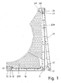
- the inner panel member 20 has at its lower end two latching recesses 21, 22 which are aligned perpendicular to each other.
- a similar locking receiving unit with two latching recesses 31, 32 is provided at the end of the base base part 30.
- First recesses 11, 31 each extend along the bottom part; second latching recesses 22, 32 are aligned perpendicular thereto and accessible from below in FIG.
- the bottom flap profile 10 is inserted with its transversely aligned to the longitudinal axis of the first latching pin 11, which points in Fig. 1 upwards, in the first recess 21 on the inner panel member 20.
- the bottom flap profile 10 also lies against the stop web 23, which forms the second recess 22 on the inner panel part.
- the second locking pin 12 of the bottom flap profile 10 is engaged in the second recess 32 on the base base profile.
- the bottom base profile 30 and the bottom flap profile 10 frontally abut each other, so that the bottom flap profile 10 also remains in alignment with the base base profile 30 and does not sag when the inner panel member 20 is pivoted away as accessible from the front inspection flap as shown by the dashed lines in Fig. 1.
- the inner panel member 20 has at its upper end at a recess 27 a hook projection 26 which is suspended on a projection in a HakenabilityausEnglishung 212 of a cover member 210 and forms a simple pivot bearing.
- the inner panel member 20 can also be easily removed without loosening connecting means.
- insulation modules 231, 232 may be provided, which are adapted to the inner contour of the roller shutter box cover.
- FIG. 2 shows the connection of base base profile 30, bottom flap profile 10 and inner panel part 20 in a detail detail of the floor area.
- the locking connection between the bottom flap profile 10 and inner panel member 20 can be achieved that a narrow object such.
- B. a screwdriver blade is driven into the gap 15, with which then the inner panel member 20 is levered.
- the bottom flap profile 10 can also take place in a mirror-image orientation with respect to the mirror axis designated by 14 in FIG.
- This mounting position of the bottom flap profile is shown in dashed lines in Fig. 3 and marked with 10 '.
- the first horizontal latching pin 11 ' is inserted into the horizontal first latching recess 31 on the base base profile 30.
- the bottom flap profile 10 ' is opened as a revision flap and allows engagement in the box with an opening gap W.
- Fig. 4 shows the roller shutter box cover 100 as part of a top roller shutter box in which a rolled-up roller shutter 220 is mounted.
- An outer panel part 213 is connected to a guide rail 214 and a lid part 210.
- the cover part 210 has a profile region 211 for latching connection with a clamping profile to be fastened to the building ceiling.
- An attachment profile 216 at the bottom can be connected to a frame profile 230 of a door or window. In turn, with the attachment profile 216, the bottom base profile 30 of the roller shutter box cover 100 is connected. Insulation modules 231, 232 insulate the roller shutter box towards the inside of the building.
Landscapes
- Engineering & Computer Science (AREA)
- Structural Engineering (AREA)
- Architecture (AREA)
- Civil Engineering (AREA)
- Operating, Guiding And Securing Of Roll- Type Closing Members (AREA)
- Blinds (AREA)
- Support Devices For Sliding Doors (AREA)
Abstract
Description
- Die Erfindung betrifft eine Rollladenkastenabdeckung mit wenigstens einem Innenblendenteil und einem senkrecht dazu ausgerichteten und darin einrastbaren Bodenteil, wobei das Innenblendenteil und das Bodenteil als Kunststoffhohlprofile ausgebildet sind.
- Aus der EP 420 054 A1 ist ein Rollladenkasten mit einer Rollladenkastenabdeckung der eingangs genannten Art bekannt. Der Rollladenkasten kann aus vier Profilen gebildet werden, die miteinander verrastbar sind. Bei der zur Gebäudeinnenseite auszurichtenden Rollladenkastenabdeckung sind ein Innen- und ein Bodenteil zu einem winkelförmigen Profil verbunden, das an einem oben liegenden Deckelteil schwenkbar gelagert ist. Das Bodenteil weist einen Rastzapfen auf, der in eine Rastaufnahme eines Rahmenaufsatzprofils einrastbar ist. Die Rollladenkastenabdeckung kann zu Revisionszwecken am Bodenteil aus der Rastverbindung gelöst und dann insgesamt um den oberen Lagerpunkt verschwenkt werden, so dass der Innenraum des Rollladenkastens von der Gebäudeinnenseite zugänglich ist.
- Durch die winkelförmige, einteilige Ausbildung müssen Boden- und Innenblendenteil beim Öffnen immer gemeinsam bewegt werden und es ist bei der bekannten Rollladenkastenabdeckung nicht möglich, eine entweder nur von unten oder nur von vorn zugängliche Revisionsklappe vorzusehen.
- Aufgabe der Erfindung ist es daher, mit derselben Rollladenkastenabdeckung verschiedene Öffnungsweisen zu ermöglichen.
- Diese Aufgabe wird bei einer Rollladenkastenabdeckung der eingangs genannten Art dadurch gelöst,
- dass das Bodenteil wenigstens zweiteilig ausgebildet ist mit einem Bodenbasisprofil und einem Bodenklappenprofil;
- dass das Innenblendenteil und das Bodenbasisprofil jeweils am Übergang zu dem dazwischen liegenden Bodenklappenprofil eine Rastausnehmungseinheit aufweisen, die jeweils wenigstens eine sich längs des Bodenteils erstreckende erste Rastaufnahmeausnehmung und wenigstens eine senkrecht dazu angeordnete zweite Rastaufnahmeausnehmung aufweisen und
- dass das Bodenklappenprofil in einem ersten Endbereich wenigstens einen längs ausgerichteten ersten Rastzapfen aufweist, der in einer der ersten Rastaufnahmeausnehmungen einrastbar ist, und in einem zweiten Endbereich wenigstens einen senkrecht ausgerichteten zweiten Rastzapfen aufweist, der in einer der zweiten Rastaufnahmeausnehmungen einrastbar ist.
- Erfindungswesentlich ist die dreiteilige Ausbildung, die beidseitige Vorsehung von Rastaufnahmeeinheiten mit zwei senkrecht zueinander ausgerichteten Rastausnehmungen sowie die Besonderheit, dass das Bodenklappenprofil an seinem einen Ende einen längs des Profils ausgerichteten Rastzapfen aufweist und am anderen Ende einen senkrecht dazu ausgerichteten Rastzapfen.
- Hierdurch können mit dem erfindungsgemäßen Profilsatz drei Öffnungsvarianten realisiert werden:
- 1. In einer ersten Verwendungsart sind Bodenklappenprofil und Innenblendenteil starr ineinander verrastet. Beim Öffnen werden beide gemeinsam hoch geschwenkt oder abgenommen, so dass sich eine maximale Öffnungsweite und beste Zugänglichkeit zum Innenraum des so abgedeckten Rollladenkastens ergibt.
- 2. In einer zweiten Verwendungsart bleiben das Bodenbasisprofil und das Bodenklappenprofil ineinander verrastet und bilden ein einheitliches Bodenteil. Die Rastverbindung zwischen Boden- und Innenblendenteil kann gelöst werden, so dass das Innenblendenteil als von vorn zugängliche Revisionsklappe abgenommen und/oder hoch geschwenkt werden kann.
- 3. In einer dritten Verwendungsart wird das Bodenklappenprofil aus der Verrastung mit dem Innenblendenteil gelöst und um die Rastaufnahmeeinheit am unteren Ende des Bodenbasisteils als Fußpunkt geschwenkt und abgenommen.
- Es muss also nur ein Profilsatz hergestellt und geliefert werden, um je nach den örtlichen Gegebenheiten verschieden öffenbare Revisionsklappen auszubilden.
- Schraubkanäle können im Profilquerschnitt jeweils vorgesehen sein, um stirnseitig Kopfstücke montieren zu können, in denen meist auch die Achse des Rollladenpanzers gelagert ist.
- Die Ausbildung als doppelwandige Kunststoff-Hohlkammerprofile, insbesondere aus Hart-PVC, führt zu einer besonders leichten Rollladenkastenabdeckung, die zudem wärmeisolierend ist.
- Vorzugsweise ist an wenigstens einer Rastaufnahmeeinheit wenigstens ein Anschlagsteg angeordnet, an den sich das benachbarte Profilteil mit seiner zur Innenseite des Rollladenkastens gewandten Oberfläche anlegt, wenn die Rastverbindung hergestellt ist. Hierdurch wird eine Eckaussteifung der Rastverbindung bewirkt. Insbesondere dient ein Profilabschnitt einer der zweiten Rastausnehmungen zugleich als Anschlagsteg.
- Durch Ergänzung der erfindungsgemäßen Rollladenkastenabdeckung mit einem Außenblendenteil, einem Deckelteil, einer Führungsschiene für einen Rollladenpanzer und einem Anschlussprofil für einen Fenster- oder Türrahmen wird ein vollständiger Aufsatz-Rollladenkasten ausgebildet.
- Die Erfindung wird nachfolgend mit Bezug auf die Zeichnung näher erläutert. Die Figuren zeigen im Einzelnen:
- Fig. 1 eine Rollladenkastenabdeckung mit von vorn öffenbarer Revisionsklappe;
- Fig. 2 den Bereich des Bodenteils in Fig. 1 im Detail;
- Fig. 3 eine Rollladenkastenabdeckung mit von unten öffenbarer Revisionsklappe;
- Fig. 4 einen Aufsatz-Rollladenkasten im Schnitt;
- Fig. 1 zeigt eine erfindungsgemäße Rollladenkastenabdeckung, die im Wesentlichen aus einem Innenblendenteil 20 und einem Bodenteil besteht, wobei das Bodenteil durch ein Bodenbasisprofil 30 und ein Bodenklappenprofil 10 gebildet ist.
- Das Innenblendenteil 20 weist an seinem unteren Ende zwei Rastausnehmungen 21, 22 auf, die senkrecht zueinander ausgerichtet sind. Spiegelbildlich dazu ist eine gleichartige Rastaufnahmeinheit mit zwei Rastausnehmungen 31, 32 am Ende des Bodenbasisteils 30 vorgesehen. Erste Rastausnehmungen 11, 31 erstrecken sich jeweils längs des Bodenteils; zweite Rastausnehmungen 22, 32 sind senkrecht dazu ausgerichtet und in Figur 1 von unten zugänglich.
- In der in Fig. 1 dargestellten Einbausituation ist das Bodenklappenprofil 10 mit seinem quer zur Längsachse ausgerichteten ersten Rastzapfen 11, der in Fig. 1 nach oben weist, in die erste Rastausnehmung 21 am Innenblendenteil 20 eingeschoben. Das Bodenklappenprofil 10 liegt zudem am Anschlagstegsteg 23 an, der die zweite Rastausnehmung 22 am Innenblendenteil bildet. Der zweite Rastzapfen 12 des Bodenklappenprofils 10 ist in die zweite Rastausnehmung 32 am Bodenbasisprofil eingerastet. Darunter, unterhalb der ersten Rastausnehmung 31, stoßen das Bodenbasisprofil 30 und das Bodenklappenprofil 10 stirnseitig voreinander, so dass das Bodenklappenprofil 10 auch dann in Flucht mit dem Bodenbasisprofil 30 liegen bleibt und nicht herab sackt, wenn das Innenblendenteil 20 als von vorn zugängliche Revisionsklappe weggeschwenkt wird, wie es durch die gestrichelten Linien in Fig. 1 dargestellt ist.
- Das Innenblendenteil 20 weist an seinem oberen Ende an einem Rücksprung 27 einen Hakenvorsprung 26 auf, der auf einem Vorsprung in einer Hakenaufnahmeausnehmung 212 eines Deckelteils 210 aufgehängt ist und ein einfaches Schwenklager bildet. Außerdem kann das Innenblendenteil 20 darüber auch ohne Lösen von Verbindungsmitteln leicht abgenommen werden.
- Es können zusätzlich Dämmstoffmodule 231, 232 vorgesehen sein, die an die Innenkontur der Rollladenkastenabdeckung angepasst sind.
- Fig. 2 zeigt die Verbindung von Bodenbasisprofil 30, Bodenklappenprofil 10 und Innenblendenteil 20 in einem Detailausschnitt des Bodenbereichs. Die Rastverbindung zwischen Bodenklappenprofil 10 und Innenblendenteil 20 kann dadurch gelöst werden, dass ein schmaler Gegenstand wie z. B. eine Schraubendreherklinge in den Spalt 15 getrieben wird, mit dem dann das Innenblendenteil 20 abgehebelt wird.
- Das Bodenklappenprofil 10 kann erfindungsgemäß auch in einer spiegelbildlichen Ausrichtung in Bezug auf die in Fig. 2 mit 14 bezeichnete Spiegelachse erfolgen. Diese Einbaulage des Bodenklappenprofils ist in Fig. 3 gestrichelt dargestellt und mit 10' gekennzeichnet. Hierbei wird der erste waagerechte Rastzapfen 11' in die waagerechte erste Rastausnehmung 31 am Bodenbasisprofil 30 eingeführt. Durch eine Schwenkbewegung, mit der der zweite Rastzapfen 12' in die zweite Rastausnehmung 22 am Innenblendenteil 20 bewegt wird, wird auch der erste Rastzapfen 11' in der Rastausnehmung 31 am Bodenbasisprofil 30 fest eingerastet.
- Durch die umgekehrte Bewegung wird das Bodenklappenprofil 10' als Revisionsklappe geöffnet und ermöglicht den Eingriff in den Kasten mit einer öffnungsspaltweite W.
- Weiterhin bildet das Bodenklappenprofil 10' in dieser Einbaulage mit dem Innenblendenteil 20 eine winkelförmige und an der Eckverbindung ausgesteifte Revisionsklappe, die auch als Ganzes verschwenkt werden kann, indem der Rastzapfen 11' aus der Rastausnehmung 31 heraus gehebelt wird.
- Fig. 4 zeigt die Rollladenkastenabdeckung 100 als Teil eines Aufsatz-Rollladenkastens, in dem ein aufgerollter Rollladenpanzer 220 gelagert ist. Ein Außenblendenteil 213 ist mit einer Führungsschiene 214 und einem Deckelteil 210 verbunden. Das Deckelteil 210 weist einen Profilbereich 211 zur Rastverbindung mit einem an der Gebäudedecke zu befestigenden Klemmprofil auf. Ein Aufsatzprofil 216 an der Unterseite kann mit einem Blendrahmenprofil 230 einer Tür oder eines Fensters verbunden werden. Mit dem Aufsatzprofil 216 wiederum ist das Bodenbasisprofil 30 der Rollladenkastenabdeckung 100 verbunden. Dämmstoffmodule 231, 232 isolieren den Rollladenkasten zur Gebäudeinnenseite hin.
Claims (7)
- Rollladenkastenabdeckung (100) (100) mit wenigstens einem Innenblendenteil (20) und einem senkrecht dazu ausgerichteten und darin einrastbaren Bodenteil (10, 10', 30), wobei das Innenblendenteil (20) und das Bodenteil (10, 10' 30) als Kunststoffhohlprofile ausgebildet sind,
dadurch gekennzeichnet,- dass das Bodenteil (10, 30) wenigstens zweiteilig ausgebildet ist mit einem Bodenbasisprofil (30) und einem Bodenklappenprofil (10; 10');- dass das Innenblendenteil (20) und das Bodenbasisprofil (30) jeweils am Übergang zu dem dazwischen liegenden Bodenklappenprofil (10; 10') eine Rastaufnahmeeinheit aufweisen, die jeweils wenigstens eine sich längs des Bodenteils erstreckende erste Rastaufnahmeausnehmung (21, 31) und wenigstens eine senkrecht dazu angeordnete zweite Rastaufnahmeausnehmung (22, 32) aufweisen und- dass das Bodenklappenprofil (10; 10') in einem ersten Endbereich wenigstens einen längs ausgerichteten ersten Rastzapfen (11, 11') aufweist, der in einer der ersten Rastaufnahmeausnehmungen (21, 31) einrastbar ist, und in einem zweiten Endbereich wenigstens einen senkrecht ausgerichteten zweiten Rastzapfen (12, 12') aufweist, der in einer der zweiten Rastaufnahmeausnehmungen (22, 32) einrastbar ist. - Rollladenkastenabdeckung (100) nach Anspruch 1, dadurch gekennzeichnet, dass in dem Bodenklappenprofil (10, 10'), dem Innenblendenteil (20) und/oder dem Bodenbasisprofil (30) wenigstens ein Schraubkanal (25) vorgesehen ist.
- Rollladenkastenabdeckung (100) nach Anspruch 1 oder 2, dadurch gekennzeichnet, dass das Bodenklappenprofil (10, 10'), das Innenblendenteil (20) und/oder das Bodenbasisprofil (30) als doppelwandige Hohlkammerprofile ausbildet sind.
- Rollladenkastenabdeckung (100) nach einem der Ansprüche 1 bis 3, dadurch gekennzeichnet, dass an wenigstens einer Rastaufnahmeeinheit wenigstens ein Anschlagsteg (23) angeordnet ist.
- Rollladenkastenabdeckung (100) nach Anspruch 4, dadurch gekennzeichnet, dass der Anschlagsteg (23) ein Profilabschnitt einer zweiten Rastausnehmung (22, 32) ist.
- Rollladenkastenabdeckung (100) nach einem der Ansprüche 1 bis 5, dadurch gekennzeichnet, dass das Innenblendenteil (20) über einen Hakenvorsprung (26), der an dem vom Bodenteil (10, 10', 30) abgewandten Ende angeordnet ist, schwenkbar in einer Hakenaufnahmeausnehmung (212) eines Deckelteils (210) lagerbar ist.
- Aufsatz-Rollladenkasten, umfassend wenigstens ein Außenblendenteil (213), ein Deckelteil (210), eine Führungsschiene (214) für einen Rollladenpanzer (220), ein Anschlussprofil (216) und eine Rollladenkastenabdeckung (100) nach einem der Ansprüche 1 bis 6.
Applications Claiming Priority (1)
| Application Number | Priority Date | Filing Date | Title |
|---|---|---|---|
| DE200510010559 DE102005010559B3 (de) | 2005-03-04 | 2005-03-04 | Rollladenkastenabdeckung |
Publications (3)
| Publication Number | Publication Date |
|---|---|
| EP1705335A2 true EP1705335A2 (de) | 2006-09-27 |
| EP1705335A3 EP1705335A3 (de) | 2010-02-17 |
| EP1705335B1 EP1705335B1 (de) | 2012-10-31 |
Family
ID=36217480
Family Applications (1)
| Application Number | Title | Priority Date | Filing Date |
|---|---|---|---|
| EP20060001074 Active EP1705335B1 (de) | 2005-03-04 | 2006-01-19 | Rolladenkastenabdeckung |
Country Status (3)
| Country | Link |
|---|---|
| EP (1) | EP1705335B1 (de) |
| DE (1) | DE102005010559B3 (de) |
| ES (1) | ES2396499T3 (de) |
Cited By (9)
| Publication number | Priority date | Publication date | Assignee | Title |
|---|---|---|---|---|
| DE102009000643A1 (de) | 2008-02-05 | 2009-08-06 | Profine Gmbh | Profilsystem für einen Kunststoff-Rollladenkasten |
| DE202013101783U1 (de) | 2013-04-24 | 2013-07-19 | Veka Ag | Wärmegedämmtes Aussteifungselement für einen Rollladenkasten und Rolladenkasten |
| DE202012103627U1 (de) * | 2012-09-21 | 2013-09-24 | Veka Ag | Aussteifungselement für einen Rollladenkasten |
| DE202012103629U1 (de) | 2012-09-21 | 2013-09-24 | Veka Ag | Befestigungsvorrichtung für ein Aussteifungselement eines Rollladenkastens |
| EP2578791A3 (de) * | 2011-10-06 | 2014-01-22 | Veka AG | Rolladenkasten |
| JP2015214856A (ja) * | 2014-05-12 | 2015-12-03 | セイキ住工株式会社 | 巻取り式スクリーン装置における巻取りボックス |
| US20170058600A1 (en) * | 2015-08-31 | 2017-03-02 | Sun Glow Window Covering Products of Canada Ltd. | Roller Shade System |
| PL424131A1 (pl) * | 2017-12-29 | 2019-07-01 | ALUPROF Spółka Akcyjna | Osłona wnęki kasety roletowej |
| GR20220100879A (el) * | 2022-10-24 | 2024-05-16 | Γεωργιος Πασχαλη Μπουδουρης | Προφιλ pvc για κουτια κουφωματων |
Families Citing this family (4)
| Publication number | Priority date | Publication date | Assignee | Title |
|---|---|---|---|---|
| DE102007025645B4 (de) * | 2006-07-05 | 2012-01-12 | Exte-Extrudertechnik Gmbh | Rollladenkasten |
| DE102007005836A1 (de) | 2007-02-01 | 2008-08-07 | Rehau Ag + Co | Gehäuse für einen Rollladenkasten sowie Rollladenkasten mit einem derartigen Gehäuse |
| EP2255058B1 (de) | 2008-02-14 | 2014-04-09 | profine GmbH | Aufsatz-Rollladenkasten sowie Profilsystem mit einem solchen Aufsatz-Rollladenkasten |
| DE202011105763U1 (de) * | 2011-09-14 | 2012-12-17 | Maco Technologie Gmbh | Aufnahmekörper für Beschattungssysteme |
Citations (3)
| Publication number | Priority date | Publication date | Assignee | Title |
|---|---|---|---|---|
| EP0420054A1 (de) | 1989-09-29 | 1991-04-03 | Thyssen Polymer Gmbh | Adapterprofil für Rolladenaufsatzelement |
| DE19948468A1 (de) | 1999-10-08 | 2001-04-19 | Roma Rolladensysteme Gmbh | Kasten für Rolläden oder dergleichen |
| EP1408193A1 (de) | 2002-10-07 | 2004-04-14 | Rehau SA | Fenster, Tür, Tür-Fenster od. dgl. mit einem Rolladenkasten, der integriert ist in einem Rahmen oder Flügel und ein solcher Rolladenkasten |
Family Cites Families (1)
| Publication number | Priority date | Publication date | Assignee | Title |
|---|---|---|---|---|
| DE19948469C2 (de) * | 1999-10-08 | 2003-08-28 | Roma Rolladensysteme Gmbh | Aufsatz-Rolladenkasten |
-
2005
- 2005-03-04 DE DE200510010559 patent/DE102005010559B3/de not_active Expired - Fee Related
-
2006
- 2006-01-19 ES ES06001074T patent/ES2396499T3/es active Active
- 2006-01-19 EP EP20060001074 patent/EP1705335B1/de active Active
Patent Citations (3)
| Publication number | Priority date | Publication date | Assignee | Title |
|---|---|---|---|---|
| EP0420054A1 (de) | 1989-09-29 | 1991-04-03 | Thyssen Polymer Gmbh | Adapterprofil für Rolladenaufsatzelement |
| DE19948468A1 (de) | 1999-10-08 | 2001-04-19 | Roma Rolladensysteme Gmbh | Kasten für Rolläden oder dergleichen |
| EP1408193A1 (de) | 2002-10-07 | 2004-04-14 | Rehau SA | Fenster, Tür, Tür-Fenster od. dgl. mit einem Rolladenkasten, der integriert ist in einem Rahmen oder Flügel und ein solcher Rolladenkasten |
Cited By (14)
| Publication number | Priority date | Publication date | Assignee | Title |
|---|---|---|---|---|
| WO2009098258A1 (de) * | 2008-02-05 | 2009-08-13 | Profine Gmbh | Profilsystem für einen kunststoff-rollladenkasten |
| DE102009000643A1 (de) | 2008-02-05 | 2009-08-06 | Profine Gmbh | Profilsystem für einen Kunststoff-Rollladenkasten |
| EP2578791A3 (de) * | 2011-10-06 | 2014-01-22 | Veka AG | Rolladenkasten |
| EP2711495A1 (de) | 2012-09-21 | 2014-03-26 | Veka AG | Aussteifungselement für einen Rollladenkasten |
| DE202012103629U1 (de) | 2012-09-21 | 2013-09-24 | Veka Ag | Befestigungsvorrichtung für ein Aussteifungselement eines Rollladenkastens |
| DE202012103627U1 (de) * | 2012-09-21 | 2013-09-24 | Veka Ag | Aussteifungselement für einen Rollladenkasten |
| EP2749726A1 (de) | 2012-09-21 | 2014-07-02 | Veka AG | Befestigungsvorrichtung für ein Aussteifungselement eines Rollladenkastens |
| DE202013101783U1 (de) | 2013-04-24 | 2013-07-19 | Veka Ag | Wärmegedämmtes Aussteifungselement für einen Rollladenkasten und Rolladenkasten |
| EP2796657A2 (de) | 2013-04-24 | 2014-10-29 | Veka AG | Wärmegedämmtes Aussteifungselement für einen Rollladenkasten und Rolladenkasten |
| JP2015214856A (ja) * | 2014-05-12 | 2015-12-03 | セイキ住工株式会社 | 巻取り式スクリーン装置における巻取りボックス |
| US20170058600A1 (en) * | 2015-08-31 | 2017-03-02 | Sun Glow Window Covering Products of Canada Ltd. | Roller Shade System |
| US10544621B2 (en) * | 2015-08-31 | 2020-01-28 | Sun Glow Window Covering Products of Canada Ltd. | Roller shade system |
| PL424131A1 (pl) * | 2017-12-29 | 2019-07-01 | ALUPROF Spółka Akcyjna | Osłona wnęki kasety roletowej |
| GR20220100879A (el) * | 2022-10-24 | 2024-05-16 | Γεωργιος Πασχαλη Μπουδουρης | Προφιλ pvc για κουτια κουφωματων |
Also Published As
| Publication number | Publication date |
|---|---|
| ES2396499T3 (es) | 2013-02-22 |
| EP1705335B1 (de) | 2012-10-31 |
| EP1705335A3 (de) | 2010-02-17 |
| DE102005010559B3 (de) | 2006-05-11 |
Similar Documents
| Publication | Publication Date | Title |
|---|---|---|
| EP1705335B1 (de) | Rolladenkastenabdeckung | |
| DE3212110A1 (de) | Verschiebbares tuer- und fensterelement | |
| DE29702516U1 (de) | Rolladenkasten für ein Fenster oder eine Türe | |
| DE102007025645B4 (de) | Rollladenkasten | |
| DE4321113A1 (de) | Rolladenfertigkasten | |
| DE2517009A1 (de) | Profilschienensatz fuer fenster- und fenstertuerrahmen | |
| DE29713536U1 (de) | Modulares Türzargensystem | |
| DE3820246A1 (de) | Profilstab und damit hergestellte duschkabinenwaende | |
| DE102009000643A1 (de) | Profilsystem für einen Kunststoff-Rollladenkasten | |
| DE19834700B4 (de) | Vorrichtung zum Verschließen einer Wandöffnung | |
| DE602004004982T2 (de) | Eckumlenkung für Türen und Fenster | |
| DE20200627U1 (de) | Flexibles Kastensystem | |
| DE3048333C2 (de) | Halterungsvorrichtung für ein Springrollo | |
| EP1106772A1 (de) | Rolladen-Aufsatzkasten | |
| EP2072744B1 (de) | Zargenprofil für eine Hebe-Schiebetür | |
| DE202007009636U1 (de) | Flügelanordnung | |
| EP0742337A2 (de) | Sektionaltor | |
| DE102004039080B4 (de) | Dichtungsanordnung | |
| DE60030719T2 (de) | Bewegliches schirmelement, z.b. eine tür | |
| DE4325698A1 (de) | Nebentür | |
| EP1777356A2 (de) | Klapp-Schwing-Dachfenster | |
| EP3832065A1 (de) | Führungsprofil für ein fenster oder eine tür mit einem rollladenkasten | |
| DE19962076C2 (de) | Schwenkbare Verbindung | |
| DE202024104108U1 (de) | Rahmen, Fenster umfassend einen Rahmen und Tür umfassend einen Rahmen | |
| DE10132766A1 (de) | Einrichtung zur nachträglichen Wärmeisolierung von Hohlräumen |
Legal Events
| Date | Code | Title | Description |
|---|---|---|---|
| PUAI | Public reference made under article 153(3) epc to a published international application that has entered the european phase |
Free format text: ORIGINAL CODE: 0009012 |
|
| AK | Designated contracting states |
Kind code of ref document: A2 Designated state(s): AT BE BG CH CY CZ DE DK EE ES FI FR GB GR HU IE IS IT LI LT LU LV MC NL PL PT RO SE SI SK TR |
|
| AX | Request for extension of the european patent |
Extension state: AL BA HR MK YU |
|
| PUAL | Search report despatched |
Free format text: ORIGINAL CODE: 0009013 |
|
| AK | Designated contracting states |
Kind code of ref document: A3 Designated state(s): AT BE BG CH CY CZ DE DK EE ES FI FR GB GR HU IE IS IT LI LT LU LV MC NL PL PT RO SE SI SK TR |
|
| AX | Request for extension of the european patent |
Extension state: AL BA HR MK YU |
|
| 17P | Request for examination filed |
Effective date: 20100526 |
|
| 17Q | First examination report despatched |
Effective date: 20100617 |
|
| AKX | Designation fees paid |
Designated state(s): AT BE BG CH CY CZ DE DK EE ES FI FR GB GR HU IE IS IT LI LT LU LV MC NL PL PT RO SE SI SK TR |
|
| GRAP | Despatch of communication of intention to grant a patent |
Free format text: ORIGINAL CODE: EPIDOSNIGR1 |
|
| GRAS | Grant fee paid |
Free format text: ORIGINAL CODE: EPIDOSNIGR3 |
|
| GRAA | (expected) grant |
Free format text: ORIGINAL CODE: 0009210 |
|
| AK | Designated contracting states |
Kind code of ref document: B1 Designated state(s): AT BE BG CH CY CZ DE DK EE ES FI FR GB GR HU IE IS IT LI LT LU LV MC NL PL PT RO SE SI SK TR |
|
| REG | Reference to a national code |
Ref country code: GB Ref legal event code: FG4D Free format text: NOT ENGLISH Ref country code: CH Ref legal event code: EP |
|
| REG | Reference to a national code |
Ref country code: AT Ref legal event code: REF Ref document number: 582133 Country of ref document: AT Kind code of ref document: T Effective date: 20121115 |
|
| REG | Reference to a national code |
Ref country code: IE Ref legal event code: FG4D Free format text: LANGUAGE OF EP DOCUMENT: GERMAN |
|
| REG | Reference to a national code |
Ref country code: DE Ref legal event code: R096 Ref document number: 502006012146 Country of ref document: DE Effective date: 20121227 |
|
| REG | Reference to a national code |
Ref country code: ES Ref legal event code: FG2A Ref document number: 2396499 Country of ref document: ES Kind code of ref document: T3 Effective date: 20130222 |
|
| REG | Reference to a national code |
Ref country code: LT Ref legal event code: MG4D |
|
| REG | Reference to a national code |
Ref country code: NL Ref legal event code: VDEP Effective date: 20121031 |
|
| PG25 | Lapsed in a contracting state [announced via postgrant information from national office to epo] |
Ref country code: LT Free format text: LAPSE BECAUSE OF FAILURE TO SUBMIT A TRANSLATION OF THE DESCRIPTION OR TO PAY THE FEE WITHIN THE PRESCRIBED TIME-LIMIT Effective date: 20121031 Ref country code: FI Free format text: LAPSE BECAUSE OF FAILURE TO SUBMIT A TRANSLATION OF THE DESCRIPTION OR TO PAY THE FEE WITHIN THE PRESCRIBED TIME-LIMIT Effective date: 20121031 Ref country code: IS Free format text: LAPSE BECAUSE OF FAILURE TO SUBMIT A TRANSLATION OF THE DESCRIPTION OR TO PAY THE FEE WITHIN THE PRESCRIBED TIME-LIMIT Effective date: 20130228 Ref country code: NL Free format text: LAPSE BECAUSE OF FAILURE TO SUBMIT A TRANSLATION OF THE DESCRIPTION OR TO PAY THE FEE WITHIN THE PRESCRIBED TIME-LIMIT Effective date: 20121031 Ref country code: SE Free format text: LAPSE BECAUSE OF FAILURE TO SUBMIT A TRANSLATION OF THE DESCRIPTION OR TO PAY THE FEE WITHIN THE PRESCRIBED TIME-LIMIT Effective date: 20121031 |
|
| PG25 | Lapsed in a contracting state [announced via postgrant information from national office to epo] |
Ref country code: GR Free format text: LAPSE BECAUSE OF FAILURE TO SUBMIT A TRANSLATION OF THE DESCRIPTION OR TO PAY THE FEE WITHIN THE PRESCRIBED TIME-LIMIT Effective date: 20130201 Ref country code: LV Free format text: LAPSE BECAUSE OF FAILURE TO SUBMIT A TRANSLATION OF THE DESCRIPTION OR TO PAY THE FEE WITHIN THE PRESCRIBED TIME-LIMIT Effective date: 20121031 Ref country code: SI Free format text: LAPSE BECAUSE OF FAILURE TO SUBMIT A TRANSLATION OF THE DESCRIPTION OR TO PAY THE FEE WITHIN THE PRESCRIBED TIME-LIMIT Effective date: 20121031 Ref country code: PT Free format text: LAPSE BECAUSE OF FAILURE TO SUBMIT A TRANSLATION OF THE DESCRIPTION OR TO PAY THE FEE WITHIN THE PRESCRIBED TIME-LIMIT Effective date: 20130228 Ref country code: CY Free format text: LAPSE BECAUSE OF FAILURE TO SUBMIT A TRANSLATION OF THE DESCRIPTION OR TO PAY THE FEE WITHIN THE PRESCRIBED TIME-LIMIT Effective date: 20121031 Ref country code: PL Free format text: LAPSE BECAUSE OF FAILURE TO SUBMIT A TRANSLATION OF THE DESCRIPTION OR TO PAY THE FEE WITHIN THE PRESCRIBED TIME-LIMIT Effective date: 20121031 |
|
| BERE | Be: lapsed |
Owner name: VEKA A.G. Effective date: 20130131 |
|
| PG25 | Lapsed in a contracting state [announced via postgrant information from national office to epo] |
Ref country code: EE Free format text: LAPSE BECAUSE OF FAILURE TO SUBMIT A TRANSLATION OF THE DESCRIPTION OR TO PAY THE FEE WITHIN THE PRESCRIBED TIME-LIMIT Effective date: 20121031 Ref country code: DK Free format text: LAPSE BECAUSE OF FAILURE TO SUBMIT A TRANSLATION OF THE DESCRIPTION OR TO PAY THE FEE WITHIN THE PRESCRIBED TIME-LIMIT Effective date: 20121031 Ref country code: CZ Free format text: LAPSE BECAUSE OF FAILURE TO SUBMIT A TRANSLATION OF THE DESCRIPTION OR TO PAY THE FEE WITHIN THE PRESCRIBED TIME-LIMIT Effective date: 20121031 Ref country code: BG Free format text: LAPSE BECAUSE OF FAILURE TO SUBMIT A TRANSLATION OF THE DESCRIPTION OR TO PAY THE FEE WITHIN THE PRESCRIBED TIME-LIMIT Effective date: 20130131 Ref country code: SK Free format text: LAPSE BECAUSE OF FAILURE TO SUBMIT A TRANSLATION OF THE DESCRIPTION OR TO PAY THE FEE WITHIN THE PRESCRIBED TIME-LIMIT Effective date: 20121031 |
|
| PG25 | Lapsed in a contracting state [announced via postgrant information from national office to epo] |
Ref country code: MC Free format text: LAPSE BECAUSE OF NON-PAYMENT OF DUE FEES Effective date: 20130131 Ref country code: RO Free format text: LAPSE BECAUSE OF FAILURE TO SUBMIT A TRANSLATION OF THE DESCRIPTION OR TO PAY THE FEE WITHIN THE PRESCRIBED TIME-LIMIT Effective date: 20121031 |
|
| REG | Reference to a national code |
Ref country code: CH Ref legal event code: PL |
|
| PLBE | No opposition filed within time limit |
Free format text: ORIGINAL CODE: 0009261 |
|
| STAA | Information on the status of an ep patent application or granted ep patent |
Free format text: STATUS: NO OPPOSITION FILED WITHIN TIME LIMIT |
|
| GBPC | Gb: european patent ceased through non-payment of renewal fee |
Effective date: 20130131 |
|
| 26N | No opposition filed |
Effective date: 20130801 |
|
| REG | Reference to a national code |
Ref country code: IE Ref legal event code: MM4A |
|
| PG25 | Lapsed in a contracting state [announced via postgrant information from national office to epo] |
Ref country code: CH Free format text: LAPSE BECAUSE OF NON-PAYMENT OF DUE FEES Effective date: 20130131 Ref country code: LI Free format text: LAPSE BECAUSE OF NON-PAYMENT OF DUE FEES Effective date: 20130131 Ref country code: BE Free format text: LAPSE BECAUSE OF NON-PAYMENT OF DUE FEES Effective date: 20130131 |
|
| REG | Reference to a national code |
Ref country code: DE Ref legal event code: R097 Ref document number: 502006012146 Country of ref document: DE Effective date: 20130801 |
|
| PG25 | Lapsed in a contracting state [announced via postgrant information from national office to epo] |
Ref country code: GB Free format text: LAPSE BECAUSE OF NON-PAYMENT OF DUE FEES Effective date: 20130131 |
|
| PG25 | Lapsed in a contracting state [announced via postgrant information from national office to epo] |
Ref country code: IE Free format text: LAPSE BECAUSE OF NON-PAYMENT OF DUE FEES Effective date: 20130119 |
|
| REG | Reference to a national code |
Ref country code: AT Ref legal event code: MM01 Ref document number: 582133 Country of ref document: AT Kind code of ref document: T Effective date: 20130119 |
|
| PG25 | Lapsed in a contracting state [announced via postgrant information from national office to epo] |
Ref country code: AT Free format text: LAPSE BECAUSE OF NON-PAYMENT OF DUE FEES Effective date: 20130119 |
|
| PG25 | Lapsed in a contracting state [announced via postgrant information from national office to epo] |
Ref country code: TR Free format text: LAPSE BECAUSE OF FAILURE TO SUBMIT A TRANSLATION OF THE DESCRIPTION OR TO PAY THE FEE WITHIN THE PRESCRIBED TIME-LIMIT Effective date: 20121031 |
|
| PG25 | Lapsed in a contracting state [announced via postgrant information from national office to epo] |
Ref country code: LU Free format text: LAPSE BECAUSE OF NON-PAYMENT OF DUE FEES Effective date: 20130119 Ref country code: HU Free format text: LAPSE BECAUSE OF FAILURE TO SUBMIT A TRANSLATION OF THE DESCRIPTION OR TO PAY THE FEE WITHIN THE PRESCRIBED TIME-LIMIT; INVALID AB INITIO Effective date: 20060119 |
|
| REG | Reference to a national code |
Ref country code: FR Ref legal event code: PLFP Year of fee payment: 11 |
|
| REG | Reference to a national code |
Ref country code: FR Ref legal event code: PLFP Year of fee payment: 12 |
|
| REG | Reference to a national code |
Ref country code: FR Ref legal event code: PLFP Year of fee payment: 13 |
|
| REG | Reference to a national code |
Ref country code: DE Ref legal event code: R082 Ref document number: 502006012146 Country of ref document: DE Representative=s name: COHAUSZ HANNIG BORKOWSKI WISSGOTT PATENTANWALT, DE |
|
| P01 | Opt-out of the competence of the unified patent court (upc) registered |
Effective date: 20230528 |
|
| PGFP | Annual fee paid to national office [announced via postgrant information from national office to epo] |
Ref country code: ES Payment date: 20240216 Year of fee payment: 19 |
|
| PGFP | Annual fee paid to national office [announced via postgrant information from national office to epo] |
Ref country code: DE Payment date: 20240119 Year of fee payment: 19 |
|
| PGFP | Annual fee paid to national office [announced via postgrant information from national office to epo] |
Ref country code: IT Payment date: 20240131 Year of fee payment: 19 Ref country code: FR Payment date: 20240123 Year of fee payment: 19 |