EP1696209B1 - Führung eines Ansteuerpfades eines beweglichen Objektes in einem Navigationssystem - Google Patents
Führung eines Ansteuerpfades eines beweglichen Objektes in einem Navigationssystem Download PDFInfo
- Publication number
- EP1696209B1 EP1696209B1 EP06003142.4A EP06003142A EP1696209B1 EP 1696209 B1 EP1696209 B1 EP 1696209B1 EP 06003142 A EP06003142 A EP 06003142A EP 1696209 B1 EP1696209 B1 EP 1696209B1
- Authority
- EP
- European Patent Office
- Prior art keywords
- moving object
- guide
- turn
- control unit
- icons
- Prior art date
- Legal status (The legal status is an assumption and is not a legal conclusion. Google has not performed a legal analysis and makes no representation as to the accuracy of the status listed.)
- Active
Links
- 238000000034 method Methods 0.000 claims description 27
- 238000013500 data storage Methods 0.000 claims description 11
- 238000010586 diagram Methods 0.000 description 3
- 238000013459 approach Methods 0.000 description 2
- 230000001419 dependent effect Effects 0.000 description 1
- 238000011161 development Methods 0.000 description 1
- 230000018109 developmental process Effects 0.000 description 1
- 238000010790 dilution Methods 0.000 description 1
- 239000012895 dilution Substances 0.000 description 1
- 239000000284 extract Substances 0.000 description 1
Images


Classifications
-
- G—PHYSICS
- G08—SIGNALLING
- G08G—TRAFFIC CONTROL SYSTEMS
- G08G1/00—Traffic control systems for road vehicles
- G08G1/09—Arrangements for giving variable traffic instructions
- G08G1/0962—Arrangements for giving variable traffic instructions having an indicator mounted inside the vehicle, e.g. giving voice messages
- G08G1/0968—Systems involving transmission of navigation instructions to the vehicle
-
- G—PHYSICS
- G01—MEASURING; TESTING
- G01C—MEASURING DISTANCES, LEVELS OR BEARINGS; SURVEYING; NAVIGATION; GYROSCOPIC INSTRUMENTS; PHOTOGRAMMETRY OR VIDEOGRAMMETRY
- G01C21/00—Navigation; Navigational instruments not provided for in groups G01C1/00 - G01C19/00
- G01C21/26—Navigation; Navigational instruments not provided for in groups G01C1/00 - G01C19/00 specially adapted for navigation in a road network
- G01C21/34—Route searching; Route guidance
- G01C21/36—Input/output arrangements for on-board computers
- G01C21/3626—Details of the output of route guidance instructions
- G01C21/3632—Guidance using simplified or iconic instructions, e.g. using arrows
-
- G—PHYSICS
- G01—MEASURING; TESTING
- G01C—MEASURING DISTANCES, LEVELS OR BEARINGS; SURVEYING; NAVIGATION; GYROSCOPIC INSTRUMENTS; PHOTOGRAMMETRY OR VIDEOGRAMMETRY
- G01C21/00—Navigation; Navigational instruments not provided for in groups G01C1/00 - G01C19/00
- G01C21/26—Navigation; Navigational instruments not provided for in groups G01C1/00 - G01C19/00 specially adapted for navigation in a road network
- G01C21/34—Route searching; Route guidance
- G01C21/36—Input/output arrangements for on-board computers
Definitions
- This description relates to a navigation system and a method of guiding a moving object through a drive path within the navigation system.
- the navigation system detects a current position using navigation messages transmitted from a plurality of GPS (global positioning system) satellites and moving-object drive state detecting signals detected by a plurality of sensors provided to the corresponding moving object, such as a gyroscope, a speed sensor and the like. If a current position of the moving object is detected, the detected current position of the moving object is matched to map data. The current position of the moving object is displayed on a display unit together with a corresponding map.
- the navigation system provides the functionality of searching a drive path of a moving object from an origination to a destination using the map data and the functionality of guiding the drive path to enable the moving object to drive along the searched drive path.
- the navigation system searches prescribed guide targets in front of the moving object, such as an intersection, an underpass, an overpass, a highway entrance/exit and the like, when the moving object is driving along the searched drive path. If the moving object approaches the searched guide target within a prescribed distance, the navigation system guides the drive path via a voice signal and the like.
- the navigation system determines if the moving object deviates from the searched drive path and drives along another, different path. If deviation from the drive path is determined by the navigation system, the navigation system informs a user of the deviation from the drive path to enable the user to correctly maneuver the moving object along the proper drive path. Therefore, the navigation system searches for the proper drive path of the moving object and guides the moving object along the proper drive path so that the given road system can be efficientiy utilized.
- the navigation system detects a current position of the moving object and determines whether a guide target is located within a set distance in front of the drive path by taking the detected current position as a reference. If the guide target is located within the set distance, the navigation system indicates a drive direction for the moving object to take from the corresponding guide target, such as indicating a left turn, using a voice signal and a drive direction icon displayed on the display unit. In guiding the drive direction of the moving object using the guide voice signal and the drive direction icon, the navigation system can accurately guide the drive direction of the moving object if the guide targets located ahead of the moving object are separated from each other by relatively large distances.
- the typical navigation system has difficulty in determining where the guide target for guiding the drive direction is accurately located.
- the user may frequently deviate from the drive path by driving the moving object in the drive direction guided according to the location of an unguided target.
- a moving object 100 sequentially drives along links between nodes 102, 104 and 106, and then turns to the right at the node 106 as an intersection to drive on the link between the node 106 and a node 108.
- a navigation system determines whether the node 106, as a guide target of a drive path, is located within a set distance ahead of the moving object 100. In particular, the navigation system determines whether the moving object 100 has arrived at a guide point P1 to guide the drive path for the node 106 as the guide target.
- the navigation system guides a right turn at the node 106 using a voice signal.
- the navigation system also displays a drive direction icon for guiding the right turn, as shown in FIG. 1b , on a display unit. The user checks the drive direction icon displayed on the display unit and then turns the moving object 100 to the right at the node 106.
- the navigation system guides a right turn of the moving object 100 at the guide point P1 corresponding to a position behind the node 104 before the moving object 100 has arrived at the node 104 or 106.
- the user of the moving object 100 may be unable to correctly determine whether to make a right turn at the node 104 or at the node 106 using the guide voice signal and the drive direction icon displayed on the display unit only. Accordingly, the user of the moving object 100 fails to correctly turn the moving object 100 to the right at the node 106, but may make a right turn at the node 104 and thus deviate from the drive path.
- the US Patent US 5890089 A describes a navigation system which operates a controller to cause a sign section of a traveling-section indicator to turn on or flicker to indicate a direction in which the car should move on.
- the US Patent US 6654024 B1 describes a method for displaying primary and secondary information in a motor vehicle by reproducing symbols on a display, the symbols are shown with different brightness according to their importance. Their brightness is changed as the importance of the information changes.
- a primary information is explained as an indication that the driver needs to get into the right-hand lane in order to turn off and a secondary information is explained as an instruction that it is necessary to leave the autobahn at the next but one exit.
- US 2003/078728 A1 describes a navigation method for a motor vehicle, the purpose of which is to display an arrow as a directional symbol on a windshield as a function of signals from a viewing direction recognition device, with the directional information being determined by a navigation device when approaching a turn-off to be selected, the arrow moves in the direction of the turn-off.
- the arrow becomes shorter and/or changes color and/or its flashing frequency.
- a rotation of the arrow on the windshield as a function of the stipulated route is also possible.
- the protection apparatus to which the navigation device is connected, has means for placing the arrow in the field of vision of the driver.
- US 6,127,969 A describes a method for outputting direction information relating to a route planned by means of a navigation system.
- a first direction indication is provided for indicating the direct direction from an instantaneous vehicle position to a remote point along the planned route, said remote point being situated a forward distance ahead of the instantaneous vehicle position and being continuously adapted in dependence on the vehicle position.
- this description is directed to a method of guiding a drive path of a moving object in a navigation system that substantially obviates one or more problems due to limitations and disadvantages of the background art.
- a method of guiding a motor vehicle having a navigation system along a drive path includesdetermining a current position of the motor vehicle with a control unit of the navigation system and providing the drive path to a display unit based on the current position of the moving object.
- the method preferably includes determining whether the motor vehicle has arrived at a complex guide point of a guide target, wherein the complex guide point preferably includes a plurality of road interchanges within a predetermined distance of each other, the road interchanges each including a road direction angle within a common angular range.
- the method Upon arrival at the complex guide point, the method preferably determines a first turn guide icon and a second turn guide icon for the guide target, wherein the first turn guide icon and the second turn guide icon collectively represent a suggested vehicle operation at the guide point and a drive direction at a position of the guide target from a plurality of previously stored turn guide icons.
- the determined turn guide icons preferably are displayed sequentially relative to the drive path throughout the vehicle operation at the guide point on a display unit.
- Implementations may include one or more of the following features.
- the common angular range is preferably approximately 15°.
- the guide icons preferably each differ in directional angle by approximately 5° or more.
- a method of guiding a moving object having a navigation system along a path includes determining a current position of the moving object with a control unit.
- the method preferably includes determining whether the moving object has arrived at a guide point of a guide target and instructing the drive path based on the current position of the moving object.
- a first turn guide icon and a second turn guide icon preferably are determined for the guide target, wherein the first turn guide icon and the second turn guide icon collectively preferably represent a suggested vehicle operation at the guide point and a drive direction at a position of the guide target from a plurality of previously stored turn guide icons.
- the determined turn guide icons preferably are sequentially displayed relative to the drive path throughout the vehicle operation at the guide point on a display unit.
- Implementations may include one or more of the following features.
- hybrid navigation preferably comprises receiving a navigation message with a GPS receiver and detecting a drive state detecting signal with a sensor unit.
- the detected current position of the moving object is matched to map data and the detected current position and map data are displayed on the display unit.
- the path is preferably searched between an origination and destination of the moving object, wherein the guide target is located on the searched drive path. Searching the path preferably includes inputting a search command to a command input unit.
- the origination of the moving object preferably is a position detected by the control unit by hybrid navigation, wherein hybrid navigation preferably comprises receiving a navigation message with a GPS receiver and detecting a drive state detecting signal with a sensor unit.
- Searching the drive path preferably includes referencing previously stored map data with the control unit, wherein the previously stored map data is preferably in a map data storage unit.
- the plurality of turn guide icons preferably differ from one another with respect to a display angle per a preset angle interval.
- Determining the turn guide icons preferably includes determining turn guide icons having display angles within a range of an angle at which the moving object should be turned from the position of the guide target.
- Sequentially displaying preferably includes determining a distance between a current position of the moving object and the position of the guide target, and sequentially displaying the turn guide icons according to the determined distance.
- the distance is preferably determined between the current position and the position of the guide target.
- the current position of the moving object is preferably determined with hybrid navigation by the control unit, wherein hybrid navigation preferably includes receiving a navigation message with a GPS receiver and detecting a drive state detecting signal with a sensor unit.
- the guide point preferably includes a complex guide point including a plurality of road interchanges within a predetermined distance of each other, the road interchanges each including a road direction angle within a common angular range.
- the common angular range is preferably 15°.
- the first and the second icons preferably differ in directional angle by approximately 5° or more.
- the moving object is a motor vehicle and the path is a driving path of the motor vehicle.
- a navigation system within a moving object for guiding the moving object along a drive path includes a satellite navigation system receiver, a sensor unit for detecting a driving direction and operating state of the moving object independently from the satellite navigation system receiver, a map data storage unit, a display unit, and a control unit.
- Implementations may include one or more of the following features.
- the control unit preferably is configured for determining whether the moving object has arrived at a guide point of a guide target for instructing the drive path based on the current position of the moving object and the driving direction and the operating state of the moving object.
- the control unit is preferably configured for determining, upon arrival at the guide point, a first turn guide icon and a second turn guide icon for the guide target, wherein the first turn guide icon and the second turn guide icon collectively represent a suggested vehicle operation at the guide point and a drive direction at a position of the guide target from a plurality of previously stored turn guide icons within the map data storage unit.
- the control unit is preferably configured for sequentially displaying the determined turn guide icons relative to the drive path throughout the vehicle operation at the guide point on the display unit.
- FIG. 2 is a block diagram of a navigation system includes a GPS receiver 210 which receives navigation messages transmitted from a plurality of GPS satellites (not shown in the drawing).
- the GPS receiver 210 calculates and outputs a value of DOP (dilution of precision) indicating a degree of reliability of the received navigation message.
- the navigation system includes a sensor unit 220 and a map data storage unit 230.
- the sensor unit 220 may include a gyroscope for detecting a drive angle of the moving object, and various sensors, such as a speed sensor for detecting a drive speed of the moving object and the like, to detect an operating state of the moving object and to output a drive state detecting signal.
- the map data storage unit 230 stores map data for searching a drive path of the moving object and for guiding the drive path.
- the navigation system includes a control unit 240 for determining a current position of the moving object with hybrid navigation.
- the control unit 240 may be included within one or more of a central processing unit (CPU) or a computer system of the navigation system.
- the control unit, or other programmable logic device that provides instruction, logic, and mathematical processing in the navigation system may also be one or more of a CPU or computer system, e.g., including an arithmetic logic unit (ALU), which performs arithmetic and logical operations, and/or an individual control unit, which extracts instructions from a memory device, such as within the navigation system, and decodes and executes the instructions, e.g., calling on the ALU when necessary.
- ALU arithmetic logic unit
- control unit 240 may be configured for operating with hybrid navigation.
- Hybrid navigation includes using the navigation messages received by the GPS receiver 210 and the drive state detecting signal of the moving object detected by the sensor unit 220.
- the control unit 240 searches the drive path from an origination to a destination using the map data stored in the map data storage unit 230.
- the control unit 240 controls the determined current position of the moving object, by verifying the accuracy of the current position of the moving object and/or matching the current position to the map data for displaying a determined current position of the moving object.
- the control unit 240 guides the moving object to drive along the searched drive path by updating the determined current position of the moving object responsive to each new set of position data received through the navigation system, e.g., through the GPS receiver 210 and sensor unit 220 with hybrid navigation.
- the control unit 240 also determines a display position on the map where a road, highway or other landmark should be named.
- the navigation system includes a display unit 250 and a command input unit 260.
- the display unit 250 displays the map data, the current position of the moving object, the drive path of the moving object and the road name at the display position determined by the control unit 240.
- the command input unit 260 includes a plurality of function keys, generates an operation command according to user manipulation of a plurality of the function keys, and inputs the generated operation command to the control unit 240.
- a guide voice generating unit 270 generates a prescribed guide voice signal to guide a drive of the moving object according to a control of the control unit 240.
- the guide voice generating unit 270 outputs the generated guide voice signal to a speaker 280 to inform a user of the moving object of the drive path of the moving object.
- the control unit 240 determines whether a search command for a drive path is inputted by a user's manipulation of the command input unit 260 (S300). If the search command for the drive path is inputted, the control unit 240 receives an origination and destination of a moving object from the command input unit 260 (S302).
- the origination of the moving object can be set to a current position of the moving object determined by the control unit 240 using hybrid navigation that utilizes navigation messages received by the GPS receiver 210 and a drive state detecting signal of the moving object detected by the sensor unit 220.
- the control unit 240 receives a value of DOP calculated by the GPS receiver 210 having received the navigation messages. If the calculated value of the DOP is a reliable value, e.g., accuracy is within an acceptable range such as 20 feet or a probability of accuracy, as a result of the determination, the control unit 240 detects a current position of the moving object using the navigation messages received by the GPS receiver 210. If the value of DOP is not a reliable value, the control unit 240 detects a current position of the moving object using the drive state detecting signal of the moving object detected by the sensor unit 220 from a last position of the moving object detected using the reliable navigation message. Therefore, it is possible to set the origination of the moving object to the current position of the moving object detected by the hybrid navigation.
- a reliable value e.g., accuracy is within an acceptable range such as 20 feet or a probability of accuracy
- the control unit 240 searches a drive path of the moving object from the origination to the destination using map data stored in the map data storage unit 230.
- the control unit 240 determines whether the moving object is driving (S306). In doing so, a determination of the drive path of the moving object can be conducted using the moving state detecting signal of the moving object detected, for example, by the sensor unit 220 of a motor vehicle.
- the control unit 240 detects the current position of the moving object by the a hybrid navigation (S308).
- the control unit 240 matches the detected current position of the moving object to the map data and displays it on the display unit 250 to enable a user to confirm the current position (S310).
- control unit 240 determines whether the moving object has arrived at a drive direction guide point for instructing a drive direction of the moving object using the determined current position of the moving object (S312). Namely, it is determined whether a guide target, such as an intersection or the like, is located ahead of the moving object and it is determined whether the moving object has arrived at the guide point to instruct the drive path for the guide target.
- a guide target such as an intersection or the like
- the control unit 240 determines a turn angle at which the moving object will turn from the guide target (S314). Namely, the control unit 240 determines the angle of a link, on which the moving object will drive after passing through the guide target, by taking a current link on which the moving object is driving as a reference. If the guide target is a complex guide target, e.g., a first intersection that supports a right turn and a neighboring intersection that is located relatively close to the first intersection such as less than a few hundred feet, the turn angle of the moving object is updated throughout the vehicle's movement through a complex guide target.
- a complex guide target e.g., a first intersection that supports a right turn and a neighboring intersection that is located relatively close to the first intersection such as less than a few hundred feet
- the control unit 240 determines a plurality of turn guide icons to display according to the determined turn angle of the moving object (S316) during the moving object's travel through an area having a complex guide target.
- the control unit 240 then sequentially selects, according to a distance between the moving object and the guide target (S318), a plurality of the determined turn guide icons to display on the display unit 250.
- the interval of the determined turn guide icons may be predetermined for particularly confusing and known intersections and/or provided by the control unit 240 for an intersection that has not been previously designated as a complex intersection or guide target.
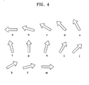
- FIGS. 4a through 4m A plurality of turn guide icons differing in display angle from each other by a predetermined angle, such as 15°, are shown in FIGS. 4a through 4m .
- the turn guide icons are prepared based on the physical attributes of the road and/or prepared and stored in advance, e.g., in the map data storage unit 230.
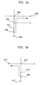
- a moving object 500 drives on a link between nodes 502, 504 and 506, turns to the right from the node 506 in a direction of 90°, and then drives on a link between the node 506 and a node 508.
- control unit 240 determines whether the moving object 50 drives to arrive at a guide point P11 for instructing a turn guide. If the moving object has arrived at the guide point P11, the control unit 240 determines an angle of the link located between the nodes 506 and 508 by taking the link between the nodes 502, 504 and 506 as a reference.
- the control unit 240 determines the turn guide icons shown in FIGS. 4ag through 4m from a plurality of the turn guide icons.
- the control unit 240 keeps determining the distance between the moving object 500 and the node 502 and sequentially selects the determined turn guide icons shown in FIGS. 4ag through 4m one by one to display on the display unit 250.
- the moving object 500 drives on a link between nodes 510 and 512 to turn to the left from the node 512 in a direction of a node 514. If so, by determining an angle of a link between the nodes 512 and 514 by taking a link between the nodes 510 and 512 as a reference in case the moving object 500 has arrived at a guide target point P12 for instructing a turn guide, the control unit 240 determines a plurality of the turn guide icons such as the icons shown in FIGS. 4a through 4g . The control unit 240 then keeps determining the distance between the moving object 500 and the node 512 and sequentially selects the determined turn guide icons shown in FIGS. 4a through 4g one by one to display on the display unit 250.
- the control unit 240 determines the turn guide icons shown in FIGS. 4g through 4j in case the moving object 500 has arrived at a guide target point P13, and then sequentially selects the determined turn guide icons shown in FIGS. 4g through 4j one by one to display on the display unit 250 according to the distance between the moving object and the node 520, such as while a motor vehicle is performing the turning operation.
- the control unit 240 determines the turn guide icons shown in FIGS. 4D through 4G in case the moving object 500 has arrived at the guide target point P13 and then sequentially selects the determined turn guide icons shown in FIGs. 4D to 4G one by one and displays each of the icons incrementally on the display unit 250 according to the distance between the moving object and the node 520.
- a plurality of the turn guide icons can be formed in various angles. For instance, a plurality of the turn guide icons are generated in advance, each 5° or 10° offset with respect to each other, and stored in the map data storage unit 230. If the moving object has not reached the guide point for instructing the turn guide as a result of the decision in the step S312, the control unit 240 determines whether the moving object has arrived at the destination (S320). If the moving object has not arrived at the destination, the control unit 240 goes back to the step S306 to detect a current position according to a drive of the moving object and repeats an operation of selecting the plurality of the turn guide icons to display on the display unit 250 in case the moving object has arrived at the guide point for instructing the turn in the drive path.
- the control unit 240 ends the drive path guide operation of the moving object.
- a plurality of the turn guide icons differing from one another in the display angle are generated in advance. If the moving object has arrived at the guide point of the guide target for instructing the drive direction, the turn guide icons belonging to the range of the angle at which the moving object is to turn are determined beforehand. The turning operation is reduced to a series of incrementally displayed turn guide icons as the motor vehicle maneuvers through a turning operation.
- the moving object has arrived at the guide target location, such as a complex guide target having multiple, similarly oriented or adjacent intersections or roads, the plurality of the selected turn guide icons are sequentially displayed.
- a user of a moving object such as a motor vehicle
- the user can accurately determine where or when to turn when approaching a confusing intersection presenting multiple and similar turning options, e.g., such as an intersection having more than one possible right turn, e.g., right turns offset with respect to each other by a specific angle. If a plurality of guide targets are located close to each other, the user can make a turn from an accurate location of the corresponding guide target to prevent the deviation from a drive path.
- a navigation system or method may guide a drive path of a moving object by providing a turning direction and angle of a moving object at an intersection.
- a navigation system or method may guide a drive path of a moving object by instructing a correct direction for a moving object to drive in the event that a pair of intersections are located close to each other.
Landscapes
- Engineering & Computer Science (AREA)
- Radar, Positioning & Navigation (AREA)
- Remote Sensing (AREA)
- Automation & Control Theory (AREA)
- Physics & Mathematics (AREA)
- General Physics & Mathematics (AREA)
- Navigation (AREA)
Claims (13)
- Verfahren zum Führen eines sich bewegenden Objekts (500) mit einem Navigationssystem entlang eines Weges, wobei das Verfahren umfasst:Bestimmen einer momentanen Position des sich bewegenden Objekts (500) unter Verwendung einer Steuereinheit (240) und Anweisen des Fahrtwegs auf der Grundlage der momentanen Position des sich bewegenden Objekts (500);Bestimmen, ob ein Führungsziel (506, 512, 522) dem sich bewegenden Objekt (500) voraus befindlich ist;Bestimmen, ob das sich bewegende Objekt (500) bei einem Führungspunkt (P11, P12, P13) angekommen ist, um den Fahrtweg für das Führungsziel (506, 512, 522) anzuweisen;Bestimmen, bei Ankunft bei dem Führungspunkt (P11, P12, P13), einer Vielzahl von Abbiegeführungspiktogrammen für das Führungsziel (506, 512, 522), wobei die Vielzahl von Abbiegeführungspiktogrammen kollektiv einen vorgeschlagenen Bewegungsobjektvorgang bei dem Führungspunkt (P11, P12, P13) und einen Abbiegewinkel darstellt, bei dem das sich bewegende Objekt (500) von dem Führungsziel (506, 512, 522) nach dem Führungspunkt (P11, P12, P13) abbiegen soll, aus einer Vielzahl von zuvor gespeicherten Abbiegeführungspiktogrammen (a-m);wobei:das Bestimmen der Abbiegeführungspiktogramme (a-m) umfasst:Bestimmen von Abbiegeführungspiktogrammen (a-m) mit Anzeigewinkeln, die voneinander um einen vorbestimmten Winkel abweichen, innerhalb eines Bereichs von einer momentanen Anbindung, auf der das sich bewegende Objekt fährt, als eine Referenz, hin zu dem Abbiegewinkel, zu dem das sich bewegende Objekt (500) von dem Führungsziel (506, 512, 522) nach dem Führungspunkt (P11, P12, P13) abbiegen soll; undsequenzielles Anzeigen der bestimmten Abbiegeführungspiktogramme (a-m) Stück für Stück, gemäß einer Distanz zwischen einer momentanen Position des sich bewegenden Objekts (500) und der Position des Führungsziels, wobei die Distanz fortlaufend bestimmt wird.
- Verfahren gemäß Anspruch 1, wobei die momentane Position des sich bewegenden Objekts (500) mit einer hybriden Navigation unter Verwendung der Steuereinheit (240) bestimmt wird, wobei die hybride Navigation ein Empfangen einer Navigationsnachricht mit einem GPS-Empfänger (210) und ein Erfassen eines Fahrtzustandserfassungssignals mit einer Sensoreinheit (220) umfasst.
- Verfahren gemäß Anspruch 1, weiterhin umfassend:Abgleichen der bestimmten momentanen Position des sich bewegenden Objekts mit Kartendaten; undAnzeigen der bestimmten momentanen Position und der Kartendaten auf der Anzeigeeinheit (250).
- Verfahren gemäß Anspruch 1, weiterhin umfassend Suchen eines Fahrtwegs zwischen einem Ursprung und einem Ziel des sich bewegenden Objekts (500), wobei das Führungsziel (506, 512, 522) auf dem gesuchten Fahrtweg befindlich ist.
- Verfahren gemäß Anspruch 4, wobei das Suchen des Wegs ein Eingeben eines Suchbefehls in eine Befehlseingabeeinheit umfasst.
- Verfahren gemäß Anspruch 4, wobei der Ursprung des sich bewegenden Objekts (500) eine Position ist, die durch die Steuereinheit (240) durch hybride Navigation erfasst ist, wobei die hybride Navigation ein Empfangen einer Navigationsnachricht mit einem GPS-Empfänger (210) und ein Erfassen eines Fahrtzustandserfassungssignals mit einer Sensoreinheit (220) umfasst.
- Verfahren gemäß Anspruch 4, wobei das Suchen des Fahrtwegs umfasst Referenzieren von zuvor gespeicherten Kartendaten unter Verwendung der Steuereinheit (240), wobei die zuvor gespeicherten Kartendaten sich in einer Kartendatenspeichereinheit (230) befinden.
- Verfahren gemäß Anspruch 1, wobei das Bestimmen der Distanz zwischen der momentanen Position des sich bewegenden Objekts (500) und der Position des Führungsziels (506, 5012, 522) umfasst Bestimmen der momentanen Position des sich bewegenden Objekts (500) mit einer hybriden Navigation durch die Steuereinheit (240), wobei die hybride Navigation ein Empfangen einer Navigationsnachricht mit einem GPS-Empfänger (210) und ein Erfassen eines Fahrtzustandserfassungssignals mit einer Sensoreinheit (220) umfasst.
- Verfahren gemäß Anspruch 1, wobei das Führungsziel (506, 512, 522) ein komplexes Führungsziel umfasst, das eine Vielzahl von Fahrbahnwechseln innerhalb einer vorbestimmten Distanz voneinander umfasst, wobei die Fahrbahnwechsel jeweils einen Fahrbahnrichtungswinkel innerhalb eines gemeinsamen Winkelbereichs umfassen.
- Verfahren gemäß Anspruch 9, wobei der gemeinsame Winkelbereich 15° beträgt.
- Verfahren gemäß Anspruch 1, wobei zuvor gespeicherte Abbiegeführungspiktogramme (a-m) jeweils in einem Richtungswinkel um ungefähr 5° oder mehr abweichen.
- Verfahren gemäß Anspruch 1, wobei der Weg ein Fahrtweg des Motorfahrzeugs ist.
- Navigationssystem innerhalb eines sich bewegenden Objekts (500) zum Führen des sich bewegenden Objekts entlang eines Fahrtwegs, wobei das System umfasst:einen Satellitennavigationssystemempfänger (210);eine Sensoreinheit (220), die konfiguriert ist, um eine Fahrtrichtung und einen Betriebszustand des sich bewegenden Objekts (500) unabhängig von dem Satellitennavigationssystemempfänger (210) zu erfassen;eine Kartendatenspeichereinheit (230);eine Anzeigeeinheit (250); undeine Steuereinheit (240), wobei die Steuereinheit (240) konfiguriert ist, um eine momentane Position des sich bewegenden Objekts (500) aus Daten zu bestimmen, die aus dem Satellitennavigationssystemempfänger (210) empfangen sind;wobei die Steuereinheit (240) konfiguriert ist, um zu bestimmen, ob ein Führungsziel (506, 512, 522) dem sich bewegenden Objekt (500) voraus befindlich ist und ob das sich bewegende Objekt (500) bei einem Führungspunkt (P11, P12, P13) angekommen ist, um den Fahrtweg für das Führungsziel (506, 512, 522) anzuweisen;wobei die Steuereinheit (240) konfiguriert ist, um zu bestimmen, bei Ankunft bei dem Führungspunkt (P11, P12, P13), einer Vielzahl von Abbiegeführungspiktogrammen für das Führungsziel (506, 512, 522), wobei die Vielzahl von Abbiegeführungspiktogrammen kollektiv einen vorgeschlagenen Bewegungsobjektvorgang bei dem Führungspunkt (P11, P12, P13) und einen Abbiegewinkel darstellt, bei dem das sich bewegende Objekt (500) von dem Führungsziel (506, 512, 522) nach dem Führungspunkt (P11, P12, P13) abbiegen soll, aus einer Vielzahl von zuvor gespeicherten Abbiegeführungspiktogrammen (am);wobei:die Steuereinheit weiterhin konfiguriert ist, um:- Abbiegeführungspiktogramme (a-m) mit Anzeigewinkeln zu bestimmen, die voneinander um einen vorbestimmten Winkel abweichen, innerhalb eines Bereichs von einer momentanen Anbindung, auf der das sich bewegende Objekt fährt, als eine Referenz, bis hin zu dem Abbiegewinkel, bei dem das sich bewegende Objekt (500) von dem Führungsziel (506, 512, 522) nach dem Führungspunkt (P11, P12, P13) abbiegen soll;- eine Distanz zwischen einer momentanen Position des sich bewegenden Objekts (500) und der Position des Führungsziels fortlaufend zu bestimmen; und- sequenziell die bestimmen Abbiegeführungspiktogramme (a-m) stückweise gemäß der Distanz anzuzeigen.
Applications Claiming Priority (1)
| Application Number | Priority Date | Filing Date | Title |
|---|---|---|---|
| KR1020050012859A KR101047719B1 (ko) | 2005-02-16 | 2005-02-16 | 네비게이션 시스템에서 이동체의 주행경로 안내방법 및 장치 |
Publications (3)
| Publication Number | Publication Date |
|---|---|
| EP1696209A2 EP1696209A2 (de) | 2006-08-30 |
| EP1696209A3 EP1696209A3 (de) | 2011-12-07 |
| EP1696209B1 true EP1696209B1 (de) | 2013-10-02 |
Family
ID=36659868
Family Applications (1)
| Application Number | Title | Priority Date | Filing Date |
|---|---|---|---|
| EP06003142.4A Active EP1696209B1 (de) | 2005-02-16 | 2006-02-16 | Führung eines Ansteuerpfades eines beweglichen Objektes in einem Navigationssystem |
Country Status (4)
| Country | Link |
|---|---|
| US (1) | US7630832B2 (de) |
| EP (1) | EP1696209B1 (de) |
| KR (1) | KR101047719B1 (de) |
| CN (1) | CN1821719B (de) |
Families Citing this family (54)
| Publication number | Priority date | Publication date | Assignee | Title |
|---|---|---|---|---|
| US8892356B1 (en) * | 2003-06-19 | 2014-11-18 | Here Global B.V. | Method and system for representing traffic signals in a road network database |
| US9341485B1 (en) | 2003-06-19 | 2016-05-17 | Here Global B.V. | Method and apparatus for representing road intersections |
| JP4792866B2 (ja) * | 2005-08-05 | 2011-10-12 | アイシン・エィ・ダブリュ株式会社 | ナビゲーションシステム |
| JP2007147577A (ja) * | 2005-10-31 | 2007-06-14 | Aisin Aw Co Ltd | 経路案内システム及び経路案内方法 |
| JP4724043B2 (ja) * | 2006-05-17 | 2011-07-13 | トヨタ自動車株式会社 | 対象物認識装置 |
| JP2008009915A (ja) * | 2006-06-30 | 2008-01-17 | Pioneer Electronic Corp | 道路標識判定装置、方法及びプログラム |
| EP2141681A4 (de) * | 2007-03-28 | 2011-07-27 | Navitime Japan Co Ltd | Kartenanzeigesystem, kartenanzeige und kartenanzeigeverfahren |
| US7908082B2 (en) * | 2007-05-04 | 2011-03-15 | The Boeing Company | Methods and systems for displaying airport moving map information |
| KR100870091B1 (ko) * | 2007-05-11 | 2008-11-25 | 팅크웨어(주) | 센서를 이용한 회전상태 판단 방법 및 장치 |
| JP4366664B2 (ja) * | 2007-06-29 | 2009-11-18 | アイシン・エィ・ダブリュ株式会社 | 自車位置認識装置及び自車位置認識プログラム |
| CN101424535B (zh) * | 2007-10-30 | 2012-05-30 | 武汉大学 | 多层道路中车辆定位方法及装置 |
| KR100939925B1 (ko) * | 2007-12-27 | 2010-02-04 | 팅크웨어(주) | 내비게이션 시스템의 교차 지점 안내 표출 심볼 표시 장치및 방법 |
| US8346465B2 (en) * | 2008-02-26 | 2013-01-01 | Apline Electronics, Inc | Method and apparatus for determining and displaying meaningful cross street for navigation system |
| JP4656177B2 (ja) * | 2008-04-14 | 2011-03-23 | トヨタ自動車株式会社 | ナビゲーション装置、操作部表示方法 |
| CN101290230B (zh) * | 2008-04-14 | 2011-03-30 | 深圳市凯立德软件技术股份有限公司 | 一种交叉路口的导航方法及使用了此导航方法的导航系统 |
| JP2011524975A (ja) | 2008-05-29 | 2011-09-08 | トムトム インターナショナル ベスローテン フエンノートシャップ | 可聴情報に関連する地図情報を変更するナビゲーション装置及び方法 |
| KR101013197B1 (ko) * | 2008-06-13 | 2011-02-10 | (주)엠앤소프트 | 차량 항법 장치 및 그의 경로 안내 방법 |
| CN101373142B (zh) * | 2008-10-16 | 2012-01-04 | 深圳市凯立德欣软件技术有限公司 | 导航系统及其交叉路口精确导航方法 |
| CN101373141B (zh) * | 2008-10-16 | 2012-01-04 | 深圳市凯立德科技股份有限公司 | 导航系统及在连续结点路段进行语音提示的导航方法 |
| US9024976B2 (en) * | 2009-03-05 | 2015-05-05 | The Invention Science Fund I, Llc | Postural information system and method |
| US20100228159A1 (en) * | 2009-03-05 | 2010-09-09 | Searete Llc, A Limited Liability Corporation Of The State Of Delaware | Postural information system and method |
| US20100228158A1 (en) * | 2009-03-05 | 2010-09-09 | Searete Llc, A Limited Liability Corporation Of The State Of Delaware | Postural information system and method including device level determining of subject advisory information based on subject status information and postural influencer status information |
| US20100228154A1 (en) * | 2009-03-05 | 2010-09-09 | Searete Llc, A Limited Liability Corporation Of The State Of Delaware | Postural information system and method including determining response to subject advisory information |
| US20100228495A1 (en) * | 2009-03-05 | 2010-09-09 | Searete Llc, A Limited Liability Corporation Of The State Of Delaware | Postural information system and method including determining subject advisory information based on prior determined subject advisory information |
| US20100225490A1 (en) * | 2009-03-05 | 2010-09-09 | Leuthardt Eric C | Postural information system and method including central determining of subject advisory information based on subject status information and postural influencer status information |
| US20100271200A1 (en) * | 2009-03-05 | 2010-10-28 | Searete Llc, A Limited Liability Corporation Of The State Of Delaware | Postural information system and method including determining response to subject advisory information |
| US20100228493A1 (en) * | 2009-03-05 | 2010-09-09 | Searete Llc, A Limited Liability Corporation Of The State Of Delaware | Postural information system and method including direction generation based on collection of subject advisory information |
| US20100228153A1 (en) * | 2009-03-05 | 2010-09-09 | Searete Llc, A Limited Liability Corporation Of The State Of Delaware | Postural information system and method |
| US20100228494A1 (en) * | 2009-03-05 | 2010-09-09 | Searete Llc, A Limited Liability Corporation Of The State Of Delaware | Postural information system and method including determining subject advisory information based on prior determined subject advisory information |
| US20100228487A1 (en) * | 2009-03-05 | 2010-09-09 | Searete Llc, A Limited Liability Corporation Of The State Of Delaware | Postural information system and method |
| US20100225474A1 (en) * | 2009-03-05 | 2010-09-09 | Searete Llc, A Limited Liability Corporation Of The State Of Delaware | Postural information system and method |
| US20100228488A1 (en) * | 2009-03-05 | 2010-09-09 | Searete Llc, A Limited Liability Corporation Of The State Of Delaware | Postural information system and method |
| US20100225491A1 (en) * | 2009-03-05 | 2010-09-09 | Searete Llc, A Limited Liability Corporation Of The State Of Delaware | Postural information system and method |
| US20100225498A1 (en) * | 2009-03-05 | 2010-09-09 | Searete Llc, A Limited Liability Corporation | Postural information system and method |
| US20100225473A1 (en) * | 2009-03-05 | 2010-09-09 | Searete Llc, A Limited Liability Corporation Of The State Of Delaware | Postural information system and method |
| US20100228492A1 (en) * | 2009-03-05 | 2010-09-09 | Searete Llc, A Limited Liability Corporation Of State Of Delaware | Postural information system and method including direction generation based on collection of subject advisory information |
| US20100228490A1 (en) * | 2009-03-05 | 2010-09-09 | Searete Llc, A Limited Liability Corporation Of The State Of Delaware | Postural information system and method |
| US8838370B2 (en) * | 2009-03-09 | 2014-09-16 | Empire Technology Development Llc | Traffic flow model to provide traffic flow information |
| US8463537B2 (en) * | 2009-06-03 | 2013-06-11 | Motorola Solutions, Inc. | Navigating to a moving destination |
| US20110087425A1 (en) * | 2009-10-08 | 2011-04-14 | Telenav, Inc. | Navigation system with map compression and method of operation thereof |
| US9140573B2 (en) * | 2010-07-23 | 2015-09-22 | Google Inc. | Path finding in a map editor |
| CN102322868A (zh) * | 2011-09-15 | 2012-01-18 | 鸿富锦精密工业(深圳)有限公司 | 汽车导航装置及汽车导航方法 |
| US9026367B2 (en) | 2012-06-27 | 2015-05-05 | Microsoft Technology Licensing, Llc | Dynamic destination navigation system |
| US10106172B2 (en) * | 2014-08-18 | 2018-10-23 | Ford Global Technologies, Llc | Shared vehicle system |
| US9909894B2 (en) | 2016-01-07 | 2018-03-06 | Here Global B.V. | Componentized junction models |
| US10568034B2 (en) | 2016-01-23 | 2020-02-18 | Blustream Corporation | Intelligent power management for monitoring a movable object |
| US10234294B2 (en) | 2016-04-01 | 2019-03-19 | Here Global B.V. | Road geometry matching with componentized junction models |
| CN107402019A (zh) * | 2016-05-19 | 2017-11-28 | 北京搜狗科技发展有限公司 | 一种视频导航的方法、装置及服务器 |
| CN108072375B (zh) * | 2016-11-09 | 2020-01-10 | 腾讯科技(深圳)有限公司 | 一种导航中的信息识别方法及终端 |
| CN108106628B (zh) * | 2016-11-25 | 2023-01-24 | 沈阳美行科技股份有限公司 | 一种引导提示标识的生成方法及装置 |
| CN108646750B (zh) * | 2018-06-08 | 2021-05-07 | 杭州电子科技大学 | 基于uwb非基站便捷式工厂agv跟随方法 |
| WO2021091039A1 (ko) * | 2019-11-06 | 2021-05-14 | 엘지전자 주식회사 | 차량용 디스플레이 장치 및 그 제어 방법 |
| CN111624636B (zh) * | 2020-05-25 | 2023-06-20 | 腾讯科技(深圳)有限公司 | 数据处理方法、装置、电子设备及计算机可读介质 |
| CN114184208A (zh) * | 2021-12-06 | 2022-03-15 | 北京中交兴路信息科技有限公司 | 为车辆提供导航线路的方法、装置、电子设备及介质 |
Citations (2)
| Publication number | Priority date | Publication date | Assignee | Title |
|---|---|---|---|---|
| US6127969A (en) * | 1997-03-17 | 2000-10-03 | U.S. Philips Corporation | Navigation system and method for outputting direction information from the navigation system |
| US20030078728A1 (en) * | 2000-08-02 | 2003-04-24 | Andreas Engelsberg | Navigation method in an automobile |
Family Cites Families (50)
| Publication number | Priority date | Publication date | Assignee | Title |
|---|---|---|---|---|
| JP2618254B2 (ja) * | 1988-02-15 | 1997-06-11 | 本田技研工業株式会社 | 走行経路表示装置 |
| US5206811A (en) * | 1989-11-10 | 1993-04-27 | Nissan Motor Company, Limited | Navigation system for automotive vehicle |
| US5654892A (en) * | 1991-10-18 | 1997-08-05 | Zexel Usa Corporation | Navigation system displaying forthcoming turns |
| JPH0634384A (ja) * | 1992-07-16 | 1994-02-08 | Zexel Corp | 車両用ナビゲーション装置 |
| US5410486A (en) * | 1992-07-20 | 1995-04-25 | Toyota Jidosha K.K. | Navigation system for guiding vehicle by voice |
| US5390122A (en) * | 1993-05-07 | 1995-02-14 | Lectron Products, Inc. | Method and apparatus for calibrating a vehicle compass system |
| US5512904A (en) * | 1994-06-13 | 1996-04-30 | Andrew Corporation | Method and apparatus of establishing a vehicle azimuth |
| US5525998A (en) * | 1994-08-01 | 1996-06-11 | Motorola, Inc. | Odometer assisted GPS navigation method |
| EP0722559B1 (de) * | 1994-08-08 | 2001-07-18 | Mannesmann VDO Aktiengesellschaft | Navigationsvorrichtung für ein landfahrzeug mit mitteln zur erzeugung einer frühzeitigen sprachnachricht mit mehreren elementen, sowie fahrzeug damit |
| US5684940A (en) * | 1995-03-13 | 1997-11-04 | Rutgers, The States University Of New Jersey | Computer-implemented method and apparatus for automatically labeling area regions of maps using two-step label placing procedure and for curved labeling of point features |
| US5627547A (en) * | 1995-04-07 | 1997-05-06 | Delco Electronics Corporation | Mapless GPS navigation system in vehicle entertainment system |
| JP3545839B2 (ja) * | 1995-06-09 | 2004-07-21 | 株式会社ザナヴィ・インフォマティクス | 現在位置算出装置 |
| JP3448134B2 (ja) * | 1995-08-25 | 2003-09-16 | アイシン・エィ・ダブリュ株式会社 | 車両用ナビゲーション装置 |
| US5874905A (en) * | 1995-08-25 | 1999-02-23 | Aisin Aw Co., Ltd. | Navigation system for vehicles |
| KR960042490A (ko) * | 1995-11-09 | 1996-12-21 | 모리 하루오 | 차량용 네비게이션(navigation) 장치 및 그를 위한 기록매체 |
| KR100224326B1 (ko) * | 1995-12-26 | 1999-10-15 | 모리 하루오 | 차량용 네비게이션장치 |
| JPH09184737A (ja) * | 1995-12-28 | 1997-07-15 | Mitsumi Electric Co Ltd | ナビゲーションシステム |
| JPH09297030A (ja) * | 1996-05-02 | 1997-11-18 | Pioneer Electron Corp | 移動体位置算出方法及び装置並びに移動体位置補正方法及び装置 |
| US6611753B1 (en) * | 1998-04-17 | 2003-08-26 | Magellan Dis, Inc. | 3-dimensional intersection display for vehicle navigation system |
| US6356840B2 (en) * | 1998-06-12 | 2002-03-12 | Mitsubishi Denki Kabushiki Kaisha | Navigation device with a three dimensional display |
| DE19906863A1 (de) * | 1999-02-18 | 2000-10-19 | Nokia Mobile Phones Ltd | Verfahren zur Navigation eines Objekts |
| JP3412684B2 (ja) * | 1999-03-01 | 2003-06-03 | アイシン・エィ・ダブリュ株式会社 | ナビゲーション装置及び該装置の記録媒体 |
| US6212471B1 (en) * | 1999-04-28 | 2001-04-03 | Lockheed Martin Corporation | Dynamic optimal sensor employment for searching an area |
| DE19944067A1 (de) * | 1999-09-14 | 2001-03-15 | Mannesmann Vdo Ag | Verfahren zur Anzeige von Primär- und Sekundärinformationen |
| DE10103714A1 (de) * | 2000-01-26 | 2001-08-16 | Daimler Chrysler Ag | Verfahren zum Erhalten präziser Straßenkarten |
| JP3455153B2 (ja) * | 2000-02-16 | 2003-10-14 | 松下電器産業株式会社 | 交差点における車線誘導案内表示方法およびそのナビゲーション装置並びに記録媒体 |
| JP3967061B2 (ja) * | 2000-03-28 | 2007-08-29 | アルパイン株式会社 | ナビゲーション装置 |
| JP2001289654A (ja) * | 2000-04-11 | 2001-10-19 | Equos Research Co Ltd | ナビゲーション装置、ナビゲーション装置の制御方法、及びそのプログラムを記録した記録媒体 |
| JP2001304903A (ja) * | 2000-04-27 | 2001-10-31 | Denso Corp | 分岐案内装置 |
| KR100353649B1 (ko) * | 2000-08-18 | 2002-09-28 | 삼성전자 주식회사 | 무선망을 이용한 네비게이션 시스템 및 그에 의한 경로안내 방법 |
| US6405107B1 (en) * | 2001-01-11 | 2002-06-11 | Gary Derman | Virtual instrument pilot: an improved method and system for navigation and control of fixed wing aircraft |
| WO2002061377A1 (fr) * | 2001-01-29 | 2002-08-08 | Mitsubishi Denki Kabushiki Kaisha | Procede de guidage routier jusqu'a une destination |
| CN1258075C (zh) * | 2001-02-14 | 2006-05-31 | 松下电器产业株式会社 | 车载导向系统 |
| KR100353652B1 (ko) * | 2001-05-03 | 2002-09-28 | 삼성전자 주식회사 | 휴대용 단말기를 이용한 네비게이션 시스템에서의경로진입 안내장치 및 방법 |
| US20030132860A1 (en) * | 2001-09-21 | 2003-07-17 | Honeywell International, Inc. | Interface for visual cueing and control for tactical flightpath management |
| DE10146744A1 (de) * | 2001-09-22 | 2003-04-17 | Bosch Gmbh Robert | Verfahren und System zum Bereitstellen von Fahrspurempfehlungen |
| KR100412720B1 (ko) * | 2001-12-19 | 2003-12-31 | 현대자동차주식회사 | 차량용 네비게이션 시스템 |
| US7327280B2 (en) * | 2002-08-15 | 2008-02-05 | California Institute Of Technology | Emergency vehicle traffic signal preemption system |
| US6771189B2 (en) * | 2002-07-17 | 2004-08-03 | Alpine Electronics, Inc. | Display method and apparatus for navigation system |
| KR100775158B1 (ko) * | 2002-10-16 | 2007-11-12 | 엘지전자 주식회사 | 교차로 회전 안내 시스템 및 그 동작 방법 |
| US20040204831A1 (en) * | 2002-10-30 | 2004-10-14 | Denis Pochuev | System and method of locating a resource device from a wireless device |
| JP4098106B2 (ja) * | 2003-01-29 | 2008-06-11 | 三菱電機株式会社 | 車両用ナビゲーションシステム |
| JP2004286559A (ja) * | 2003-03-20 | 2004-10-14 | Mitsubishi Electric Corp | 車両用ナビゲーションシステムおよび経路案内方法 |
| US9341485B1 (en) * | 2003-06-19 | 2016-05-17 | Here Global B.V. | Method and apparatus for representing road intersections |
| KR100811232B1 (ko) * | 2003-07-18 | 2008-03-07 | 엘지전자 주식회사 | 턴 바이 턴 네비게이션 시스템 및 차기 안내방법 |
| US7054745B1 (en) * | 2003-09-03 | 2006-05-30 | Microsoft Corporation | Method and system for generating driving directions |
| KR100982058B1 (ko) * | 2003-10-20 | 2010-09-13 | 엘지전자 주식회사 | 이동체의 지도 데이터 관리 방법 |
| JP4211620B2 (ja) * | 2004-01-30 | 2009-01-21 | 株式会社デンソー | カーナビゲーション装置 |
| US7353111B2 (en) * | 2004-05-14 | 2008-04-01 | Nissan Motor Co., Ltd. | Navigation system performing route guidance for vehicle |
| US20060085128A1 (en) * | 2004-10-15 | 2006-04-20 | Grafe V G | User-friendly directional device |
-
2005
- 2005-02-16 KR KR1020050012859A patent/KR101047719B1/ko active IP Right Grant
-
2006
- 2006-02-16 US US11/276,170 patent/US7630832B2/en active Active
- 2006-02-16 EP EP06003142.4A patent/EP1696209B1/de active Active
- 2006-02-16 CN CN200610008540XA patent/CN1821719B/zh active Active
Patent Citations (2)
| Publication number | Priority date | Publication date | Assignee | Title |
|---|---|---|---|---|
| US6127969A (en) * | 1997-03-17 | 2000-10-03 | U.S. Philips Corporation | Navigation system and method for outputting direction information from the navigation system |
| US20030078728A1 (en) * | 2000-08-02 | 2003-04-24 | Andreas Engelsberg | Navigation method in an automobile |
Also Published As
| Publication number | Publication date |
|---|---|
| KR101047719B1 (ko) | 2011-07-08 |
| EP1696209A2 (de) | 2006-08-30 |
| US20060195258A1 (en) | 2006-08-31 |
| CN1821719B (zh) | 2012-02-29 |
| KR20060091614A (ko) | 2006-08-21 |
| EP1696209A3 (de) | 2011-12-07 |
| CN1821719A (zh) | 2006-08-23 |
| US7630832B2 (en) | 2009-12-08 |
Similar Documents
| Publication | Publication Date | Title |
|---|---|---|
| EP1696209B1 (de) | Führung eines Ansteuerpfades eines beweglichen Objektes in einem Navigationssystem | |
| US7653484B2 (en) | Method for determining deviation of a mobile object in a navigation system from a travel route | |
| EP1369667B1 (de) | Fahrzeug-reiseleiteinrichtung und verfahren zum leiten eines fahrzeugs | |
| US6211798B1 (en) | Process and guidance system for ensuring reliable guidance of a vehicle | |
| EP1724555A2 (de) | Verfahren zum Anzeigen von Information in einem Navigationssystem | |
| US20150160032A1 (en) | Vehicular navigation system | |
| JP2006258548A (ja) | 車両用ナビゲーション装置 | |
| JP4936070B2 (ja) | ナビゲーション装置及びナビゲーションプログラム | |
| JP2006053109A (ja) | 車両用ナビゲーション装置及び車両用ナビゲーション装置の経路案内方法 | |
| JP5276922B2 (ja) | 現在位置算出装置 | |
| JP3757104B2 (ja) | ナビゲーション装置 | |
| JP5574810B2 (ja) | ナビゲーション装置、位置補正方法 | |
| JPH0580697A (ja) | 車両誘導装置 | |
| JP5445287B2 (ja) | 車載ナビゲーション装置 | |
| JP2006064661A (ja) | ナビゲーション装置 | |
| JPH07332993A (ja) | ナビゲーション装置 | |
| JP2003021527A (ja) | ナビゲーション装置、表示方法、及びプログラム | |
| KR100667483B1 (ko) | 네비게이션 시스템의 맵 매칭방법 | |
| JPH08304101A (ja) | ナビゲーション装置 | |
| JP3025802B2 (ja) | 経路誘導装置 | |
| JP2795206B2 (ja) | 経路案内装置 | |
| JP2746168B2 (ja) | 経路案内装置 | |
| JP2006064672A (ja) | ナビゲーション装置 | |
| KR100634002B1 (ko) | 네비게이션 시스템의 텍스트 데이터 필터링방법 | |
| JP2012173269A (ja) | 車載用表示装置 |
Legal Events
| Date | Code | Title | Description |
|---|---|---|---|
| PUAI | Public reference made under article 153(3) epc to a published international application that has entered the european phase |
Free format text: ORIGINAL CODE: 0009012 |
|
| 17P | Request for examination filed |
Effective date: 20060216 |
|
| AK | Designated contracting states |
Kind code of ref document: A2 Designated state(s): AT BE BG CH CY CZ DE DK EE ES FI FR GB GR HU IE IS IT LI LT LU LV MC NL PL PT RO SE SI SK TR |
|
| AX | Request for extension of the european patent |
Extension state: AL BA HR MK YU |
|
| RAP1 | Party data changed (applicant data changed or rights of an application transferred) |
Owner name: LG ELECTRONICS INC. |
|
| PUAL | Search report despatched |
Free format text: ORIGINAL CODE: 0009013 |
|
| AK | Designated contracting states |
Kind code of ref document: A3 Designated state(s): AT BE BG CH CY CZ DE DK EE ES FI FR GB GR HU IE IS IT LI LT LU LV MC NL PL PT RO SE SI SK TR |
|
| AX | Request for extension of the european patent |
Extension state: AL BA HR MK YU |
|
| RIC1 | Information provided on ipc code assigned before grant |
Ipc: G01C 21/36 20060101ALI20111031BHEP Ipc: G01C 21/34 20060101AFI20111031BHEP |
|
| 17Q | First examination report despatched |
Effective date: 20120627 |
|
| AKX | Designation fees paid |
Designated state(s): AT BE BG CH CY CZ DE DK EE ES FI FR GB GR HU IE IS IT LI LT LU LV MC NL PL PT RO SE SI SK TR |
|
| GRAP | Despatch of communication of intention to grant a patent |
Free format text: ORIGINAL CODE: EPIDOSNIGR1 |
|
| INTG | Intention to grant announced |
Effective date: 20130425 |
|
| GRAS | Grant fee paid |
Free format text: ORIGINAL CODE: EPIDOSNIGR3 |
|
| GRAA | (expected) grant |
Free format text: ORIGINAL CODE: 0009210 |
|
| AK | Designated contracting states |
Kind code of ref document: B1 Designated state(s): AT BE BG CH CY CZ DE DK EE ES FI FR GB GR HU IE IS IT LI LT LU LV MC NL PL PT RO SE SI SK TR |
|
| REG | Reference to a national code |
Ref country code: GB Ref legal event code: FG4D |
|
| REG | Reference to a national code |
Ref country code: CH Ref legal event code: EP Ref country code: AT Ref legal event code: REF Ref document number: 634819 Country of ref document: AT Kind code of ref document: T Effective date: 20131015 |
|
| REG | Reference to a national code |
Ref country code: IE Ref legal event code: FG4D |
|
| REG | Reference to a national code |
Ref country code: DE Ref legal event code: R096 Ref document number: 602006038631 Country of ref document: DE Effective date: 20131128 |
|
| REG | Reference to a national code |
Ref country code: AT Ref legal event code: MK05 Ref document number: 634819 Country of ref document: AT Kind code of ref document: T Effective date: 20131002 |
|
| REG | Reference to a national code |
Ref country code: NL Ref legal event code: VDEP Effective date: 20131002 |
|
| PG25 | Lapsed in a contracting state [announced via postgrant information from national office to epo] |
Ref country code: SI Free format text: LAPSE BECAUSE OF FAILURE TO SUBMIT A TRANSLATION OF THE DESCRIPTION OR TO PAY THE FEE WITHIN THE PRESCRIBED TIME-LIMIT Effective date: 20131002 |
|
| REG | Reference to a national code |
Ref country code: LT Ref legal event code: MG4D |
|
| PG25 | Lapsed in a contracting state [announced via postgrant information from national office to epo] |
Ref country code: IS Free format text: LAPSE BECAUSE OF FAILURE TO SUBMIT A TRANSLATION OF THE DESCRIPTION OR TO PAY THE FEE WITHIN THE PRESCRIBED TIME-LIMIT Effective date: 20140202 Ref country code: SE Free format text: LAPSE BECAUSE OF FAILURE TO SUBMIT A TRANSLATION OF THE DESCRIPTION OR TO PAY THE FEE WITHIN THE PRESCRIBED TIME-LIMIT Effective date: 20131002 Ref country code: CZ Free format text: LAPSE BECAUSE OF FAILURE TO SUBMIT A TRANSLATION OF THE DESCRIPTION OR TO PAY THE FEE WITHIN THE PRESCRIBED TIME-LIMIT Effective date: 20131002 Ref country code: FI Free format text: LAPSE BECAUSE OF FAILURE TO SUBMIT A TRANSLATION OF THE DESCRIPTION OR TO PAY THE FEE WITHIN THE PRESCRIBED TIME-LIMIT Effective date: 20131002 Ref country code: LT Free format text: LAPSE BECAUSE OF FAILURE TO SUBMIT A TRANSLATION OF THE DESCRIPTION OR TO PAY THE FEE WITHIN THE PRESCRIBED TIME-LIMIT Effective date: 20131002 Ref country code: BE Free format text: LAPSE BECAUSE OF FAILURE TO SUBMIT A TRANSLATION OF THE DESCRIPTION OR TO PAY THE FEE WITHIN THE PRESCRIBED TIME-LIMIT Effective date: 20131002 Ref country code: NL Free format text: LAPSE BECAUSE OF FAILURE TO SUBMIT A TRANSLATION OF THE DESCRIPTION OR TO PAY THE FEE WITHIN THE PRESCRIBED TIME-LIMIT Effective date: 20131002 |
|
| PG25 | Lapsed in a contracting state [announced via postgrant information from national office to epo] |
Ref country code: PL Free format text: LAPSE BECAUSE OF FAILURE TO SUBMIT A TRANSLATION OF THE DESCRIPTION OR TO PAY THE FEE WITHIN THE PRESCRIBED TIME-LIMIT Effective date: 20131002 Ref country code: LV Free format text: LAPSE BECAUSE OF FAILURE TO SUBMIT A TRANSLATION OF THE DESCRIPTION OR TO PAY THE FEE WITHIN THE PRESCRIBED TIME-LIMIT Effective date: 20131002 Ref country code: CY Free format text: LAPSE BECAUSE OF FAILURE TO SUBMIT A TRANSLATION OF THE DESCRIPTION OR TO PAY THE FEE WITHIN THE PRESCRIBED TIME-LIMIT Effective date: 20131002 Ref country code: AT Free format text: LAPSE BECAUSE OF FAILURE TO SUBMIT A TRANSLATION OF THE DESCRIPTION OR TO PAY THE FEE WITHIN THE PRESCRIBED TIME-LIMIT Effective date: 20131002 Ref country code: ES Free format text: LAPSE BECAUSE OF FAILURE TO SUBMIT A TRANSLATION OF THE DESCRIPTION OR TO PAY THE FEE WITHIN THE PRESCRIBED TIME-LIMIT Effective date: 20131002 |
|
| PG25 | Lapsed in a contracting state [announced via postgrant information from national office to epo] |
Ref country code: PT Free format text: LAPSE BECAUSE OF FAILURE TO SUBMIT A TRANSLATION OF THE DESCRIPTION OR TO PAY THE FEE WITHIN THE PRESCRIBED TIME-LIMIT Effective date: 20140203 |
|
| REG | Reference to a national code |
Ref country code: DE Ref legal event code: R097 Ref document number: 602006038631 Country of ref document: DE |
|
| PG25 | Lapsed in a contracting state [announced via postgrant information from national office to epo] |
Ref country code: EE Free format text: LAPSE BECAUSE OF FAILURE TO SUBMIT A TRANSLATION OF THE DESCRIPTION OR TO PAY THE FEE WITHIN THE PRESCRIBED TIME-LIMIT Effective date: 20131002 |
|
| PLBE | No opposition filed within time limit |
Free format text: ORIGINAL CODE: 0009261 |
|
| STAA | Information on the status of an ep patent application or granted ep patent |
Free format text: STATUS: NO OPPOSITION FILED WITHIN TIME LIMIT |
|
| PG25 | Lapsed in a contracting state [announced via postgrant information from national office to epo] |
Ref country code: SK Free format text: LAPSE BECAUSE OF FAILURE TO SUBMIT A TRANSLATION OF THE DESCRIPTION OR TO PAY THE FEE WITHIN THE PRESCRIBED TIME-LIMIT Effective date: 20131002 Ref country code: RO Free format text: LAPSE BECAUSE OF FAILURE TO SUBMIT A TRANSLATION OF THE DESCRIPTION OR TO PAY THE FEE WITHIN THE PRESCRIBED TIME-LIMIT Effective date: 20131002 Ref country code: IT Free format text: LAPSE BECAUSE OF FAILURE TO SUBMIT A TRANSLATION OF THE DESCRIPTION OR TO PAY THE FEE WITHIN THE PRESCRIBED TIME-LIMIT Effective date: 20131002 |
|
| 26N | No opposition filed |
Effective date: 20140703 |
|
| PG25 | Lapsed in a contracting state [announced via postgrant information from national office to epo] |
Ref country code: MC Free format text: LAPSE BECAUSE OF FAILURE TO SUBMIT A TRANSLATION OF THE DESCRIPTION OR TO PAY THE FEE WITHIN THE PRESCRIBED TIME-LIMIT Effective date: 20131002 Ref country code: LU Free format text: LAPSE BECAUSE OF FAILURE TO SUBMIT A TRANSLATION OF THE DESCRIPTION OR TO PAY THE FEE WITHIN THE PRESCRIBED TIME-LIMIT Effective date: 20140216 Ref country code: DK Free format text: LAPSE BECAUSE OF FAILURE TO SUBMIT A TRANSLATION OF THE DESCRIPTION OR TO PAY THE FEE WITHIN THE PRESCRIBED TIME-LIMIT Effective date: 20131002 |
|
| REG | Reference to a national code |
Ref country code: CH Ref legal event code: PL |
|
| REG | Reference to a national code |
Ref country code: DE Ref legal event code: R097 Ref document number: 602006038631 Country of ref document: DE Effective date: 20140703 |
|
| PG25 | Lapsed in a contracting state [announced via postgrant information from national office to epo] |
Ref country code: CH Free format text: LAPSE BECAUSE OF NON-PAYMENT OF DUE FEES Effective date: 20140228 Ref country code: LI Free format text: LAPSE BECAUSE OF NON-PAYMENT OF DUE FEES Effective date: 20140228 |
|
| REG | Reference to a national code |
Ref country code: IE Ref legal event code: MM4A |
|
| PG25 | Lapsed in a contracting state [announced via postgrant information from national office to epo] |
Ref country code: IE Free format text: LAPSE BECAUSE OF NON-PAYMENT OF DUE FEES Effective date: 20140216 |
|
| REG | Reference to a national code |
Ref country code: FR Ref legal event code: PLFP Year of fee payment: 11 |
|
| PG25 | Lapsed in a contracting state [announced via postgrant information from national office to epo] |
Ref country code: BG Free format text: LAPSE BECAUSE OF FAILURE TO SUBMIT A TRANSLATION OF THE DESCRIPTION OR TO PAY THE FEE WITHIN THE PRESCRIBED TIME-LIMIT Effective date: 20131002 |
|
| PG25 | Lapsed in a contracting state [announced via postgrant information from national office to epo] |
Ref country code: GR Free format text: LAPSE BECAUSE OF FAILURE TO SUBMIT A TRANSLATION OF THE DESCRIPTION OR TO PAY THE FEE WITHIN THE PRESCRIBED TIME-LIMIT Effective date: 20140103 |
|
| PG25 | Lapsed in a contracting state [announced via postgrant information from national office to epo] |
Ref country code: HU Free format text: LAPSE BECAUSE OF FAILURE TO SUBMIT A TRANSLATION OF THE DESCRIPTION OR TO PAY THE FEE WITHIN THE PRESCRIBED TIME-LIMIT; INVALID AB INITIO Effective date: 20060216 Ref country code: TR Free format text: LAPSE BECAUSE OF FAILURE TO SUBMIT A TRANSLATION OF THE DESCRIPTION OR TO PAY THE FEE WITHIN THE PRESCRIBED TIME-LIMIT Effective date: 20131002 |
|
| REG | Reference to a national code |
Ref country code: FR Ref legal event code: PLFP Year of fee payment: 12 |
|
| REG | Reference to a national code |
Ref country code: FR Ref legal event code: PLFP Year of fee payment: 13 |
|
| PGFP | Annual fee paid to national office [announced via postgrant information from national office to epo] |
Ref country code: FR Payment date: 20230105 Year of fee payment: 18 |
|
| PGFP | Annual fee paid to national office [announced via postgrant information from national office to epo] |
Ref country code: DE Payment date: 20240105 Year of fee payment: 19 Ref country code: GB Payment date: 20240105 Year of fee payment: 19 |