EP1693152B1 - Vorrichtung zur Nachbearbeitung von Kantenstreifen an plattenförmigen Werkstücken - Google Patents
Vorrichtung zur Nachbearbeitung von Kantenstreifen an plattenförmigen Werkstücken Download PDFInfo
- Publication number
- EP1693152B1 EP1693152B1 EP06000155A EP06000155A EP1693152B1 EP 1693152 B1 EP1693152 B1 EP 1693152B1 EP 06000155 A EP06000155 A EP 06000155A EP 06000155 A EP06000155 A EP 06000155A EP 1693152 B1 EP1693152 B1 EP 1693152B1
- Authority
- EP
- European Patent Office
- Prior art keywords
- polishing
- polishing agent
- unit
- compressed air
- tool
- Prior art date
- Legal status (The legal status is an assumption and is not a legal conclusion. Google has not performed a legal analysis and makes no representation as to the accuracy of the status listed.)
- Expired - Lifetime
Links
Images
Classifications
-
- B—PERFORMING OPERATIONS; TRANSPORTING
- B24—GRINDING; POLISHING
- B24B—MACHINES, DEVICES, OR PROCESSES FOR GRINDING OR POLISHING; DRESSING OR CONDITIONING OF ABRADING SURFACES; FEEDING OF GRINDING, POLISHING, OR LAPPING AGENTS
- B24B9/00—Machines or devices designed for grinding edges or bevels on work or for removing burrs; Accessories therefor
- B24B9/002—Machines or devices designed for grinding edges or bevels on work or for removing burrs; Accessories therefor for travelling workpieces
-
- B—PERFORMING OPERATIONS; TRANSPORTING
- B24—GRINDING; POLISHING
- B24B—MACHINES, DEVICES, OR PROCESSES FOR GRINDING OR POLISHING; DRESSING OR CONDITIONING OF ABRADING SURFACES; FEEDING OF GRINDING, POLISHING, OR LAPPING AGENTS
- B24B57/00—Devices for feeding, applying, grading or recovering grinding, polishing or lapping agents
- B24B57/02—Devices for feeding, applying, grading or recovering grinding, polishing or lapping agents for feeding of fluid, sprayed, pulverised, or liquefied grinding, polishing or lapping agents
-
- B—PERFORMING OPERATIONS; TRANSPORTING
- B24—GRINDING; POLISHING
- B24B—MACHINES, DEVICES, OR PROCESSES FOR GRINDING OR POLISHING; DRESSING OR CONDITIONING OF ABRADING SURFACES; FEEDING OF GRINDING, POLISHING, OR LAPPING AGENTS
- B24B9/00—Machines or devices designed for grinding edges or bevels on work or for removing burrs; Accessories therefor
- B24B9/02—Machines or devices designed for grinding edges or bevels on work or for removing burrs; Accessories therefor characterised by a special design with respect to properties of materials specific to articles to be ground
- B24B9/20—Machines or devices designed for grinding edges or bevels on work or for removing burrs; Accessories therefor characterised by a special design with respect to properties of materials specific to articles to be ground of plastics
-
- B—PERFORMING OPERATIONS; TRANSPORTING
- B05—SPRAYING OR ATOMISING IN GENERAL; APPLYING FLUENT MATERIALS TO SURFACES, IN GENERAL
- B05C—APPARATUS FOR APPLYING FLUENT MATERIALS TO SURFACES, IN GENERAL
- B05C1/00—Apparatus in which liquid or other fluent material is applied to the surface of the work by contact with a member carrying the liquid or other fluent material, e.g. a porous member loaded with a liquid to be applied as a coating
- B05C1/006—Apparatus in which liquid or other fluent material is applied to the surface of the work by contact with a member carrying the liquid or other fluent material, e.g. a porous member loaded with a liquid to be applied as a coating for applying liquid or other fluent material to the edges of essentially flat articles
Definitions
- the invention relates to a continuous machine for processing plate-shaped workpieces, on the narrow sides edge strips are approached.
- These edge strips consist of a polishable for the purpose of surface finish plastic material, and there is provided a device for post-processing of these edge strips, which has a grinding unit.
- a continuous machine of the type mentioned a so-called edge banding machine with a Kantenanleimaggregat is equipped with other, the Kantenanleimaggregat in the direction of flow downstream devices for post-processing of the applied to the narrow sides of the plate-shaped workpieces edge strip.
- These include mainly Kantenfräsaggregate that make a trimming of the edge strip to remove excess material over the plate broadsides.
- Such a processing unit provided for a continuous machine, with which both milled and ground can be made, is known from the document DE 102 38 983 A1 known.
- edge strips are available, which in particular consist of an acrylic material and which must be polished in the final processing.
- acrylic edges technically referred to as polymethyl methacrylate "PMMA”
- PMMA polymethyl methacrylate
- the invention is therefore an object of the invention to provide a continuous machine with a post-processing device of the type mentioned, with the polishing of the workpieces can be carried out in an uninterrupted run.
- a continuous machine of the aforementioned type characterized in that the grinding unit is provided with a polishing tool, such as a polishing pad or a polishing belt, and a polish applicator with at least one polishing agent discharging nozzle is present, that the polishing applicator with a polishing agent under pressure feeding Polishing agent supply device is connected and that the grinding unit, the polisher applicator and the polishing agent supply device for the purpose of automating the polishing process with the program control of the continuous machine are linked.
- a polishing tool such as a polishing pad or a polishing belt
- a polish applicator with at least one polishing agent discharging nozzle is present
- the polishing applicator with a polishing agent under pressure feeding Polishing agent supply device is connected and that the grinding unit, the polisher applicator and the polishing agent supply device for the purpose of automating the polishing process with the program control of the continuous machine are linked.
- the new device can be incorporated with their integrated into the continuous machine components in the automatic processing sequence in a continuous process. It is important that the necessary polishing agent on the one hand in sufficient and on the other hand not excessively fed to the polishing tool of the grinding unit or applied to the surface of the edge strips. Accordingly, the nozzle discharging the polishing tool is aligned either with the polishing tool or with the edge strip. Furthermore, the polishing device according to the invention is equipped with such controllable devices that can be linked to the program control of the continuous machine and can be controlled accordingly program.
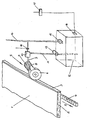
- the drawing shows a schematic representation of the post-processing area for the polishing of a continuous edge banding machine.
- a plate-shaped workpiece 1 which has a core 2 made of a wood material, which is provided on the plate broad sides with a cover layer. At least one of the narrow sides of such workpieces 1 is provided with an edge strip 3, which is applied by a Kantenanleimaggregat the machine and trimmed by means of downstream Fräsaggregate to complete flush with its edges with the plate broadsides.
- the edge strip 3 consists of a polishable plastic material, in particular an acrylic material, which can be polished to a high gloss on its exposed surface.
- the polishing tool 6 is driven by a frequency-controlled electric motor 7 in order to be able to control the rotational speed and the direction of rotation of the polishing tool 6.
- the polishing tool 6 is aligned with its axis of rotation inclined to the direction of passage of the workpiece 1, it can also Depending on how it is for the generation of the gloss image on the surface of the edge strip 3 is advantageous.
- grinding unit 5 In the drawing, only one grinding unit 5 is shown, but it can be several such grinding units 5 are used, which have different tasks, for example, to make a cleaning of the surface to be polished edge band 3 on the workpieces 1 before the polishing process.
- different polishing and / or cleaning agents can be used, in the further reference is made only to a polishing agent, which is required directly for the high gloss production.
- the viscous or pasty polishing agent can either be applied to the surface in the area on the edge strip 3 of the workpieces 1, which tapers on the polishing tool 6, on the other hand, the polishing agent can also be applied to the polishing tool 6.
- the polishing agent can also be applied to the polishing tool 6. The latter is the case in the embodiment shown in the drawing.
- a polishing agent discharging nozzle 8 is arranged on the polishing tool 6, which is connected via a pipe 9 with a metering device 10 for the polishing agent.
- the metering device 10 is supplied to the polishing agent via a pressure line 11 which is connected to a reservoir 12.
- a feed pump 13 is inserted into the pressure line 11, which, like other components, is part of a polishing agent supply device 11-15.
- the control of the dosing device 10, which is part of the entire polishing agent application device 8-10, can be carried out electrically or, as in the case of the exemplary embodiment, pneumatically.
- the metering device 10 is connected via a compressed air line 14 to a source of compressed air, into which at the input of the metering device 10, an electrically actuated valve 18 is inserted, which may be integrated into the metering device 10.
- the promotion of the polishing agent from the reservoir 12 via the pressure line 11 to the metering device 10 can also be done pneumatically.
- the reservoir 12 is pressurized with compressed air and is connected to the compressed air line 14 via a pressure regulator 15.
- a level sensor 16 is disposed on the reservoir 12, which is electrically connected to an evaluation unit 17, via which generates a signal for the required refilling of the reservoir 12 becomes.
Landscapes
- Engineering & Computer Science (AREA)
- Mechanical Engineering (AREA)
- Finish Polishing, Edge Sharpening, And Grinding By Specific Grinding Devices (AREA)
Description
- Die Erfindung bezieht sich auf eine Durchlaufmaschine zur Bearbeitung plattenförmiger Werkstücke, an deren Schmalseiten Kantenstreifen angefahren werden. Diese Kantenstreifen bestehen aus einem zwecks Oberflächenvergütung polierbaren Kunststoffmaterial, und es ist eine Vorrichtung zur Nachbearbeitung dieser Kantenstreifen vorgesehen, die ein Schleifaggregat aufweist.
- Eine Durchlaufmaschine der genannten Art, eine sogenannte Kantenanleimmaschine mit einem Kantenanleimaggregat, ist mit weiteren, dem Kantenanleimaggregat in der Durchlaufrichtung nachgeordneten Vorrichtungen zur Nachbearbeitung des auf die Schmalseiten der plattenförmigen Werkstücke aufgebrachten Kantenstreifens ausgestattet. Dazu gehören vornehmlich Kantenfräsaggregate, die eine Besäumung des Kantenstreifens vornehmen, um Überstände über die Plattenbreitseiten abzutragen.
- Ein solches für eine Durchlaufmaschine vorgesehenes Bearbeitungsaggregat, mit welchem sowohl gefräst als auch geschliffen werden kann, ist aus dem Dokument
DE 102 38 983 A1 bekannt. - Es gibt auch schon Nachbearbeitungsvorrichtungen, um aus Kunststoff bestehende Kantenstreifen an ihren freiliegenden Außenseiten nachzubearbeiten, hierbei geht es insbesondere um die Beseitigung des bei der spannehmenden Bearbeitung des Kantenstreifens auftretenden Weißbruchs. Solche Vorrichtungen weisen Ziehklingen oder Druckrollen auf, die auf die Oberfläche des an ihnen entlanglaufenden Kantenstreifens einwirken.
- Solche Oberflächenbearbeitungen reichen nicht aus, wenn an den Kantenstreifen eine hochglänzende Oberfläche erzeugt werden soll. Hierfür stehen Kantenstreifen zur Verfügung, die insbesondere aus einem Acrylmaterial bestehen und die bei der abschliessenden Bearbeitung poliert werden müssen. Solche Acrylkanten, fachlich als Polymethylmethacrylat "PMMA" bezeichnet, können mit dafür geeigneten Poliermitteln auf einen sehr hohen Glanzgrad poliert werden. Der Poliervorgang wird in der Möbelindustrie noch heute meistens manuell durchgeführt, nachdem die plattenförmigen Möbelteile die Kantenanleimmaschine verlassen haben.
- Es ist auch bekannt, die Acrylkanten maschinell zu polieren, was bis jetzt nur selten praktiziert wird. Dafür werden separate Poliermaschinen eingesetzt, die relativ groß dimensioniert sind, weswegen sie schon vom Platzbedarf her unbeliebt sind. Auch bei derartigen Poliermaschinen wird das zu verwendende Poliermittel von Hand aufgetragen. Eine solche maschinelle Polierbearbeitung ist kostenaufwendig, was sowohl die Investitions- als auch die Betriebskosten betrifft
- Andererseits ist es aus dem Dokument
DE 14 27 517 A1 bekannt, Wachs als Poliermittel mittels einer Vorrichtung auf Schleif- und Polierscheiben aufzubringen, wobei diese Wachse eine feste oder halbfeste Konsistenz haben. Aus dem DokumentJP 07 241770 A - Der Erfindung liegt deshalb die Aufgabe zugrunde, eine Durchlaufmaschine mit einer Nachbearbeitungsvorrichtung der eingangs genannten Art zu schaffen, mit der sich ein Polieren der Werkstücke im ununterbrochenen Durchlauf durchführen läßt.
- Diese Aufgabe wird bei einer Durchlaufmaschine der vorgenannten Art dadurch gelöst, daß das Schleifaggregat mit einem Polierwerkzeug, wie einer Polierscheibe oder einem Polierband, versehen und eine Poliermittelauftragseinrichtung mit zumindest einer das Poliermittel austragenden Düse vorhanden ist, daß die Polierauftragseinrichtung mit einer das Poliermittel unter Druck zuführenden Poliermittelversorgungseinrichtung verbunden ist und daß das Schleifaggregat, die Poliermittelauftragseinrichtung und die Poliermittelversorgungseinrichtung zwecks Automatisierung des Poliervorganges mit der Programmsteuerung der Durchlaufmaschine verknüpft sind.
- Für die Erfindung ist wesentlich, daß die neue Vorrichtung mit ihren in die Durchlaufmaschine integrierten Bauteilen sich in den automatischen Bearbeitungsablauf im Durchlaufverfahren eingliedern läßt. Wichtig hierbei ist, daß das notwendige Poliermittel zum einen in ausreichender und zum anderen nicht in überschüssiger Weise dem Polierwerkzeug des Schleifaggregates zugeführt oder auf die Oberfläche der Kantenstreifen aufgetragen wird. Dementsprechend ist die das Polierwerkzeug austragende Düse entweder auf das Polierwerkzeug oder auf den Kantenstreifen ausgerichtet. Des weiteren ist die erfindungsgemäße Poliervorrichtung mit solchen steuerbaren Einrichtungen ausgestattet, die mit der Programmsteuerung der Durchlaufmaschine verknüpft und entsprechend programmgesteuert werden können.
- Vorteilhafte Ausgestaltungsmerkmale der Erfindung ergeben sich aus den Unteransprüchen und aus der nachstehenden Beschreibung.
- Die Erfindung wird nachfolgend anhand der Zeichnung an einem Ausführungsbeispiel noch näher erläutert. Die Zeichnung zeigt in schematischer Darstellung den Nachbearbeitungsbereich für das Polieren einer im Durchlauf arbeitenden Kantenanleimmaschine.
- Im einzelnen erkennt man in der Zeichnung ein plattenförmiges Werkstück 1, welches einen Kern 2 aus einem Holzwerkstoff aufweist, welcher an den Plattenbreitseiten mit einer Deckschicht versehen ist. Zumindest eine der Schmalseiten solcher Werkstücke 1 ist mit einem Kantenstreifen 3 versehen, der von einem Kantenanleimaggregat der Maschine aufgetragen und mittels nachgeordneter Fräsaggregate besäumt ist, um mit seinen Kanten bündig mit den Plattenbreitseiten abzuschließen. Der Kantenstreifen 3 besteht aus einem polierbaren Kunststoffmaterial, insbesondere einem Acrylwerkstoff, der an seiner freiliegenden Oberfläche auf Hochglanz poliert werden kann.
- Dies besorgt ein Schleifaggregat 5 mit einem Polierwerkzeug 6, welches beim Ausführungsbeispiel als Polierscheibe ausgebildet ist, wofür jedoch auch ein Polierband in Betracht kommen kann. Angetrieben wird das Polierwerkzeug 6 von einem frequenzgesteuerten Elektromotor 7, um die Drehzahl und die Drehrichtung des Polierwerkzeugs 6 steuern zu können. Das Polierwerkzeug 6 ist mit seiner Rotationsachse geneigt zur Durchlaufrichtung des Werkstücks 1 ausgerichtet, es können auch andere Ausrichtungen in Betracht kommen, je nachdem wie es für die Erzeugung des Glanzbildes auf der Oberfläche des Kantenstreifens 3 von Vorteil ist.
- In der Zeichnung ist lediglich ein Schleifaggregat 5 dargestellt, es können jedoch mehrere solcher Schleifaggregate 5 zum Einsatz kommen, die unterschiedliche Aufgaben haben, um beispielsweise vor dem Poliervorgang eine Reinigung der zu polierenden Oberfläche der Kantenstreifen 3 an den Werkstücken 1 vornehmen zu können. Dazu können unterschiedliche Polier- und/oder Reinigungsmittel Verwendung finden, im weiteren wird nur auf ein Poliermittel Bezug genommen, welches unmittelbar für die Hochglanzerzeugung erforderlich ist.
- Das zähflüssige oder pasteuse Poliermittel kann entweder auf die Oberfläche in demjenigen Bereich auf den Kantenstreifen 3 der Werkstücke 1 aufgetragen werden, der auf das Polierwerkzeug 6 zuläuft, andererseits kann das Poliermittel auch auf das Polierwerkzeug 6 aufgetragen werden. Letzteres ist bei dem in der Zeichnung dargestellten Ausführungsbeispiel der Fall.
- Dazu ist an dem Polierwerkzeug 6 eine das Poliermittel austragende Düse 8 angeordnet, die über ein Rohr 9 mit einer Dosiereinrichtung 10 für das Poliermittel verbunden ist. Der Dosiervorrichtung 10 wird das Poliermittel über eine Druckleitung 11 zugeführt, die an einen Vorratsbehälter 12 angeschlossen ist. Nahe dem Vorratsratsbehälter 12 ist in die Druckleitung 11 eine Förderpumpe 13 eingefügt, die ebenso wie weitere Komponenten Teil einer Poliermittelversorgungseinrichtung 11 - 15 ist.
- Die Steuerung der Dosiervorrichtung 10, die Teil der gesamten Poliermittelauftragseinrichtung 8 - 10 ist, kann elektrisch oder wie im Falle des Ausführungsbeispiels pneumatisch erfolgen. Dazu ist die Dosiervorrichtung 10 über eine Druckluftleitung 14 an eine Druckluftquelle angeschlossen, in die am Eingang der Dosiervorrichtung 10 ein elektrisch betätigbares Ventil 18 eingefügt ist, welches in die Dosiervorrichtung 10 integriert sein kann.
- Die Förderung des Poliermittels aus dem Vorratsbehälter 12 über die Druckleitung 11 zur Dosiervorrichtung 10 hin kann auch pneumatisch erfolgen. In diesem Fall wird der Vorratsbehälter 12 mit Druckluft beaufschlagt und ist mit der Druckluftleitung 14 über einen Druckregler 15 verbunden.
- Um bei fortlaufenden Bearbeitungsvorgängen in der Durchlaufmaschine den zur Neige gehenden Vorrat des Poliermittels im Vorratsbehälter 12 rechtzeitig anzuzeigen, ist am Vorratsbehälter 12 ein Füllstandssensor 16 angeordnet, der elektrisch mit einer Auswerteeinheit 17 verbunden ist, über die ein Signal für das erforderliche Nachfüllen des Vorratsbehälters 12 generiert wird.
Claims (11)
- Durchlaufmaschine zur Bearbeitung plattenförmiger Werkstücke (1), an deren Schmalseiten Kantenstreifen (3) angefahren werden, wobei die Kantenstreifen (3) aus einem zwecks Oberflächenvergütung polierbaren Kunststoffmaterial bestehen und eine Vorrichtung zur Nachbearbeitung dieser Kantenstreifen (3) vorgesehen ist, die wenigstens ein Schleifaggregat (5) aufweist,
dadurch gekennzeichnet,
daß das Schleifaggregat (5) mit einem Polierwerkzeug (6), wie einer Polierscheibe oder einem Polierband, versehen, und eine Poliermittelauftragseinrichtung (8 - 10) mit zumindest einer das Poliermittel austragenden Düse (8) vorhanden ist,
daß die Poliermittelauftragseinrichtung (8 - 10) mit einer das Poliermittel unter Druck zuführenden Poliermittelversorgungseinrichtung (11 - 15) verbunden ist
und daß das Schleifaggregat (5), die Poliermittelauftragseinrichtung (8 - 10) und die Poliermittelversorgungseinrichtung (11 - 15) zwecks Automatisierung des Poliervorganges mit der Programmsteuerung der Durchlaufmaschine verknüpft sind. - Vorrichtung nach Anspruch 1,
dadurch gekennzeichnet
daß das Polierwerkzeug (6) eine Polierscheibe ist. - Vorrichtung nach Anspruch 1,
dadurch gekennzeichnet,
daß das Polierwerkzeug (6) ein Polierband ist. - Vorrichtung nach einem der Ansprüche 1 - 3,
dadurch gekennzeichnet,
daß die das Poliermittel austragende Düse (8) auf das Polierwerkzeug (6) ausgerichtet ist. - Vorrichtung nach einem der Ansprüche 1 - 3,
dadurch gekennzeichnet,
daß die das Poliermittel austragende Düse (8) auf den auf das Polierwerkzeug (6) zulaufenden Bereich des Kantenstreifens (3) an den Werkstücken (1) ausgerichtet ist. - Vorrichtung nach einem der Ansprüche 1 - 5,
dadurch gekennzeichnet,
daß die Poliermittelauftragseinrichtung (8 - 10) eine Dosiervorrichtung (10) für das Poliermittel aufweist. - Vorrichtung nach Anspruch 6,
dadurch gekennzeichnet,
daß die Dosiervorrichtung (10) für das Poliermittel mittels Druckluft gesteuert ist. - Vorrichtung nach Anspruch 6 oder 7,
dadurch gekennzeichnet,
daß die Poliermittelversorgungseinrichtung (11 - 15) einen Vorratsbehälter (12) für das Poliermittel aufweist, der mittels einer Druckleitung (11) mit der Dosiervorrichtung (10) der Poliermittelauftragseinrichtung (8 - 10) verbunden ist. - Vorrichtung nach Anspruch 8,
dadurch gekennzeichnet,
daß am Vorratsbehälter (12) eine Förderpumpe (13) angeordnet ist, an der die Druckleitung (11) angeschlossen ist. - Vorrichtung nach Anspruch 8,
dadurch gekennzeichnet,
daß der Vorratsbehälter (12) mittels einer Druckluftleitung (14) an eine Druckluftquelle zwecks Druckbeaufschlagung zur Erzeugung des Förderdrucks in der Druckluftleitung (11) angeschlossen ist. - Vorrichtung nach Anspruch 9 oder 10,
dadurch gekennzeichnet,
daß am Vorratsbehälter (12) ein Füllstandssensor (16) angeordnet ist.
Priority Applications (1)
| Application Number | Priority Date | Filing Date | Title |
|---|---|---|---|
| PL06000155T PL1693152T3 (pl) | 2005-02-17 | 2006-01-05 | Urządzenie do wykończającej obróbki krawędziowych listew na płytowych przedmiotach obrabianych |
Applications Claiming Priority (1)
| Application Number | Priority Date | Filing Date | Title |
|---|---|---|---|
| DE200520002637 DE202005002637U1 (de) | 2005-02-17 | 2005-02-17 | Vorrichtung zur Nachbearbeitung von Kantenstreifen an plattenförmigen Werkstücken |
Publications (2)
| Publication Number | Publication Date |
|---|---|
| EP1693152A1 EP1693152A1 (de) | 2006-08-23 |
| EP1693152B1 true EP1693152B1 (de) | 2008-03-19 |
Family
ID=34485926
Family Applications (1)
| Application Number | Title | Priority Date | Filing Date |
|---|---|---|---|
| EP06000155A Expired - Lifetime EP1693152B1 (de) | 2005-02-17 | 2006-01-05 | Vorrichtung zur Nachbearbeitung von Kantenstreifen an plattenförmigen Werkstücken |
Country Status (4)
| Country | Link |
|---|---|
| EP (1) | EP1693152B1 (de) |
| DE (2) | DE202005002637U1 (de) |
| ES (1) | ES2300067T3 (de) |
| PL (1) | PL1693152T3 (de) |
Cited By (3)
| Publication number | Priority date | Publication date | Assignee | Title |
|---|---|---|---|---|
| CN106695017A (zh) * | 2016-12-08 | 2017-05-24 | 安徽金元素复合材料有限公司 | 一种金属倒角切割机 |
| CN110421433A (zh) * | 2019-08-16 | 2019-11-08 | 宁波暮春自动化科技有限公司 | 一种自动板材磨边机 |
| CN111843628A (zh) * | 2020-07-24 | 2020-10-30 | 南京迈得特光学有限公司 | 非规则玻璃镜片尖角倒角方法 |
Families Citing this family (11)
| Publication number | Priority date | Publication date | Assignee | Title |
|---|---|---|---|---|
| DE202011000515U1 (de) | 2011-03-08 | 2011-05-05 | Riepe, Angelika | Vorrichtung zur Kantenbearbeitung einer Platte, vorzugsweise einer Möbelplatte |
| DE102014101682A1 (de) * | 2014-02-11 | 2015-08-13 | Bernd Riepe | Mobile Holzbearbeitungsmaschine |
| DE102015121284A1 (de) * | 2015-12-07 | 2017-06-08 | Lcm Gmbh | Vorrichtung zur Nachbearbeitung mindestens eines plattenförmigen Werkstücks |
| CN105643454A (zh) * | 2016-01-29 | 2016-06-08 | 山东农业大学 | 小板件打磨压紧机 |
| CN106475867B (zh) * | 2016-11-30 | 2018-07-10 | 无锡同心塑料制品有限公司 | 一种泡沫塑料板磨边设备 |
| CN110757852A (zh) * | 2019-11-01 | 2020-02-07 | 于景彬 | 一种三聚氰胺板的造型方法 |
| CN112123082A (zh) * | 2020-09-27 | 2020-12-25 | 湖南润华新材料有限公司 | 一种用于消防箱箱体生产线用板材的抛光锯边装置 |
| CN112428059A (zh) * | 2020-11-05 | 2021-03-02 | 华传锦 | 一种用于孔板边缘打磨装置 |
| CN112476141A (zh) * | 2020-11-27 | 2021-03-12 | 李冰斌 | 一种大型塑料板边角打磨装置 |
| CN114102314A (zh) * | 2021-11-22 | 2022-03-01 | 浙江万筑装饰设计工程有限公司 | 一种可定距离输送的装潢板材加工用多角度打磨装置 |
| DE102023135316A1 (de) * | 2023-12-15 | 2025-06-18 | Riepe Gmbh & Co. Kg | Verfahren und Vorrichtung zum Bearbeiten eines Kantenbereichs einer Möbelplatte |
Family Cites Families (4)
| Publication number | Priority date | Publication date | Assignee | Title |
|---|---|---|---|---|
| GB961754A (en) * | 1961-08-04 | 1964-06-24 | Johan Gunnar Lundin | Method and apparatus for applying abrasive and polishing waxes |
| US4065333A (en) * | 1977-03-31 | 1977-12-27 | National Gypsum Company | Facing sheet edge trimming |
| JPH07241770A (ja) * | 1994-03-08 | 1995-09-19 | Nissan Motor Co Ltd | 研削液供給装置 |
| DE10238983B4 (de) * | 2002-08-20 | 2009-07-16 | Homag Holzbearbeitungssysteme Ag | Bearbeitungsaggregat für eine Durchlaufmaschine |
-
2005
- 2005-02-17 DE DE200520002637 patent/DE202005002637U1/de not_active Expired - Lifetime
-
2006
- 2006-01-05 PL PL06000155T patent/PL1693152T3/pl unknown
- 2006-01-05 EP EP06000155A patent/EP1693152B1/de not_active Expired - Lifetime
- 2006-01-05 DE DE502006000463T patent/DE502006000463D1/de not_active Expired - Lifetime
- 2006-01-05 ES ES06000155T patent/ES2300067T3/es not_active Expired - Lifetime
Cited By (3)
| Publication number | Priority date | Publication date | Assignee | Title |
|---|---|---|---|---|
| CN106695017A (zh) * | 2016-12-08 | 2017-05-24 | 安徽金元素复合材料有限公司 | 一种金属倒角切割机 |
| CN110421433A (zh) * | 2019-08-16 | 2019-11-08 | 宁波暮春自动化科技有限公司 | 一种自动板材磨边机 |
| CN111843628A (zh) * | 2020-07-24 | 2020-10-30 | 南京迈得特光学有限公司 | 非规则玻璃镜片尖角倒角方法 |
Also Published As
| Publication number | Publication date |
|---|---|
| EP1693152A1 (de) | 2006-08-23 |
| DE202005002637U1 (de) | 2005-04-21 |
| ES2300067T3 (es) | 2008-06-01 |
| PL1693152T3 (pl) | 2008-08-29 |
| DE502006000463D1 (de) | 2008-04-30 |
Similar Documents
| Publication | Publication Date | Title |
|---|---|---|
| EP1693152A1 (de) | Vorrichtung zur Nachbearbeitung von Kantenstreifen an plattenförmigen Werkstücken | |
| DE102016204249A1 (de) | Vorrichtung zum Bearbeiten und/oder Beschichten eines Werkstücks | |
| WO2007012438A1 (de) | Vorrichtung zum bearbeiten eines band- oder plattenförmigen metallischen werkstücks | |
| DE3308586A1 (de) | Vorrichtung zum spitzenlosen aussenhonen oder -schleifen | |
| DE69501670T2 (de) | Maschine zum Behandeln von Skisohlen, insbesondere durch Schleifen | |
| EP1331068A2 (de) | Schneidwerkzeug umfassend einen Schneidkopf mit einer Antriebsvorrichtung | |
| DE2612981A1 (de) | Selbsttaetige zustell-steuervorrichtung fuer eine schleifmaschine | |
| DE1084469B (de) | Maschine zum Auftragen von Klebstoffen, Leimen od. dgl. auf Furniere, Bretter, Papier, Pappe od. dgl. | |
| DE102007000208A1 (de) | Schleifapparat mit Schlammentfernungsvorrichtung und Schlammentfernungsverfahren | |
| DE102018121626A1 (de) | Poliervorrichtung | |
| DE4439132A1 (de) | Verfahren und Vorrichtung zur Herstellung von Schleif- bzw. Polierwerkzeugen | |
| AT524765B1 (de) | Vorrichtung zum Bearbeiten der Laufkanten eines Sportgerätes | |
| DE202014009163U1 (de) | Vorrichtung zum spitzenlosen Rundschleifen | |
| DE2810565A1 (de) | Kantenanleimmaschine | |
| DE4121518C2 (de) | Verfahren für die Feinbearbeitung von Werkstückoberflächen | |
| DE19742665B4 (de) | Verfahren zum Schleifen mittels anhaftender Schleifmittel | |
| DE2645913C3 (de) | Verfahren zum Abrunden der Außenkanten der Gewindegänge am Gewindeeinlauf und/oder Gewindeauslauf einer Gewinderolle | |
| DE4414857C1 (de) | Schärfmaschine zum Bearbeiten der Kanten von flächigen Werkstücken, insbesondere aus Leder | |
| DE69228753T2 (de) | Verfahren zum abstreifen eines plastischen materials und vorrichtung zur durchführung dieses verfahrens | |
| DE3235132A1 (de) | Verfahren zum schleifen von saegeblattzaehnen und schleifmaschine zur durchfuehrung dieses verfahrens | |
| DE202005008623U1 (de) | Einrichtung zum Schleifen und/oder Polieren des Kantenbereiches eines plattenförmigen Werkstückes | |
| DE2030214A1 (de) | Schleifelement zum Feinglatten von Holzformteilen sowie Verfahren und Ma schine zum Durchfuhren des Feinglattens | |
| DE1427517A1 (de) | Verfahren und Vorrichtung zum Aufbringen von Wachs auf Schleif- und Polierscheiben od.dgl. | |
| DE19640416B4 (de) | Schleifvorrichtung für das Messer von Entschleif- oder Spaltmaschinen | |
| DE2511167A1 (de) | Schleifautomat |
Legal Events
| Date | Code | Title | Description |
|---|---|---|---|
| PUAI | Public reference made under article 153(3) epc to a published international application that has entered the european phase |
Free format text: ORIGINAL CODE: 0009012 |
|
| AK | Designated contracting states |
Kind code of ref document: A1 Designated state(s): AT BE BG CH CY CZ DE DK EE ES FI FR GB GR HU IE IS IT LI LT LU LV MC NL PL PT RO SE SI SK TR |
|
| AX | Request for extension of the european patent |
Extension state: AL BA HR MK YU |
|
| 17P | Request for examination filed |
Effective date: 20070130 |
|
| AKX | Designation fees paid |
Designated state(s): DE ES FR IT PL |
|
| GRAP | Despatch of communication of intention to grant a patent |
Free format text: ORIGINAL CODE: EPIDOSNIGR1 |
|
| GRAS | Grant fee paid |
Free format text: ORIGINAL CODE: EPIDOSNIGR3 |
|
| GRAA | (expected) grant |
Free format text: ORIGINAL CODE: 0009210 |
|
| AK | Designated contracting states |
Kind code of ref document: B1 Designated state(s): DE ES FR IT PL |
|
| RIN1 | Information on inventor provided before grant (corrected) |
Inventor name: KALMBACH, WILHELM Inventor name: GAUSS, ACHIM |
|
| REF | Corresponds to: |
Ref document number: 502006000463 Country of ref document: DE Date of ref document: 20080430 Kind code of ref document: P |
|
| REG | Reference to a national code |
Ref country code: ES Ref legal event code: FG2A Ref document number: 2300067 Country of ref document: ES Kind code of ref document: T3 |
|
| REG | Reference to a national code |
Ref country code: PL Ref legal event code: T3 |
|
| ET | Fr: translation filed | ||
| PLBE | No opposition filed within time limit |
Free format text: ORIGINAL CODE: 0009261 |
|
| STAA | Information on the status of an ep patent application or granted ep patent |
Free format text: STATUS: NO OPPOSITION FILED WITHIN TIME LIMIT |
|
| 26N | No opposition filed |
Effective date: 20081222 |
|
| PGFP | Annual fee paid to national office [announced via postgrant information from national office to epo] |
Ref country code: PL Payment date: 20101206 Year of fee payment: 6 |
|
| PGFP | Annual fee paid to national office [announced via postgrant information from national office to epo] |
Ref country code: FR Payment date: 20110120 Year of fee payment: 6 |
|
| REG | Reference to a national code |
Ref country code: FR Ref legal event code: ST Effective date: 20120928 |
|
| PG25 | Lapsed in a contracting state [announced via postgrant information from national office to epo] |
Ref country code: FR Free format text: LAPSE BECAUSE OF NON-PAYMENT OF DUE FEES Effective date: 20120131 |
|
| REG | Reference to a national code |
Ref country code: PL Ref legal event code: LAPE |
|
| PG25 | Lapsed in a contracting state [announced via postgrant information from national office to epo] |
Ref country code: PL Free format text: LAPSE BECAUSE OF NON-PAYMENT OF DUE FEES Effective date: 20120105 |
|
| PGFP | Annual fee paid to national office [announced via postgrant information from national office to epo] |
Ref country code: DE Payment date: 20170125 Year of fee payment: 12 |
|
| PGFP | Annual fee paid to national office [announced via postgrant information from national office to epo] |
Ref country code: IT Payment date: 20170127 Year of fee payment: 12 Ref country code: ES Payment date: 20170126 Year of fee payment: 12 |
|
| REG | Reference to a national code |
Ref country code: DE Ref legal event code: R119 Ref document number: 502006000463 Country of ref document: DE |
|
| PG25 | Lapsed in a contracting state [announced via postgrant information from national office to epo] |
Ref country code: DE Free format text: LAPSE BECAUSE OF NON-PAYMENT OF DUE FEES Effective date: 20180801 |
|
| PG25 | Lapsed in a contracting state [announced via postgrant information from national office to epo] |
Ref country code: IT Free format text: LAPSE BECAUSE OF NON-PAYMENT OF DUE FEES Effective date: 20180105 |
|
| REG | Reference to a national code |
Ref country code: ES Ref legal event code: FD2A Effective date: 20190730 |
|
| PG25 | Lapsed in a contracting state [announced via postgrant information from national office to epo] |
Ref country code: ES Free format text: LAPSE BECAUSE OF NON-PAYMENT OF DUE FEES Effective date: 20180106 |