EP1684092A1 - Automotive radar with mechanically scanned monopulse antenna - Google Patents
Automotive radar with mechanically scanned monopulse antenna Download PDFInfo
- Publication number
- EP1684092A1 EP1684092A1 EP05018190A EP05018190A EP1684092A1 EP 1684092 A1 EP1684092 A1 EP 1684092A1 EP 05018190 A EP05018190 A EP 05018190A EP 05018190 A EP05018190 A EP 05018190A EP 1684092 A1 EP1684092 A1 EP 1684092A1
- Authority
- EP
- European Patent Office
- Prior art keywords
- angle
- receiving antennas
- antenna
- radar
- azimuth
- Prior art date
- Legal status (The legal status is an assumption and is not a legal conclusion. Google has not performed a legal analysis and makes no representation as to the accuracy of the status listed.)
- Withdrawn
Links
- 238000001514 detection method Methods 0.000 claims abstract description 108
- 239000003989 dielectric material Substances 0.000 claims description 5
- 238000000034 method Methods 0.000 abstract description 33
- 230000008569 process Effects 0.000 abstract description 2
- 238000012545 processing Methods 0.000 description 43
- 238000010586 diagram Methods 0.000 description 9
- 230000006872 improvement Effects 0.000 description 8
- 230000004044 response Effects 0.000 description 7
- 238000013459 approach Methods 0.000 description 6
- 230000008859 change Effects 0.000 description 6
- 230000003247 decreasing effect Effects 0.000 description 5
- 230000000694 effects Effects 0.000 description 5
- 230000003595 spectral effect Effects 0.000 description 3
- 230000003044 adaptive effect Effects 0.000 description 2
- 230000007423 decrease Effects 0.000 description 2
- 238000013461 design Methods 0.000 description 2
- 230000006866 deterioration Effects 0.000 description 2
- XEEYBQQBJWHFJM-UHFFFAOYSA-N iron Substances [Fe] XEEYBQQBJWHFJM-UHFFFAOYSA-N 0.000 description 2
- 229910052742 iron Inorganic materials 0.000 description 2
- 230000009467 reduction Effects 0.000 description 2
- 239000000758 substrate Substances 0.000 description 2
- NNJVILVZKWQKPM-UHFFFAOYSA-N Lidocaine Chemical compound CCN(CC)CC(=O)NC1=C(C)C=CC=C1C NNJVILVZKWQKPM-UHFFFAOYSA-N 0.000 description 1
- 230000005540 biological transmission Effects 0.000 description 1
- 239000000428 dust Substances 0.000 description 1
- 229940025586 lidopen Drugs 0.000 description 1
- 239000003595 mist Substances 0.000 description 1
- 238000012986 modification Methods 0.000 description 1
- 230000004048 modification Effects 0.000 description 1
Images






Classifications
-
- H—ELECTRICITY
- H01—ELECTRIC ELEMENTS
- H01Q—ANTENNAS, i.e. RADIO AERIALS
- H01Q3/00—Arrangements for changing or varying the orientation or the shape of the directional pattern of the waves radiated from an antenna or antenna system
- H01Q3/02—Arrangements for changing or varying the orientation or the shape of the directional pattern of the waves radiated from an antenna or antenna system using mechanical movement of antenna or antenna system as a whole
- H01Q3/08—Arrangements for changing or varying the orientation or the shape of the directional pattern of the waves radiated from an antenna or antenna system using mechanical movement of antenna or antenna system as a whole for varying two co-ordinates of the orientation
-
- G—PHYSICS
- G01—MEASURING; TESTING
- G01S—RADIO DIRECTION-FINDING; RADIO NAVIGATION; DETERMINING DISTANCE OR VELOCITY BY USE OF RADIO WAVES; LOCATING OR PRESENCE-DETECTING BY USE OF THE REFLECTION OR RERADIATION OF RADIO WAVES; ANALOGOUS ARRANGEMENTS USING OTHER WAVES
- G01S13/00—Systems using the reflection or reradiation of radio waves, e.g. radar systems; Analogous systems using reflection or reradiation of waves whose nature or wavelength is irrelevant or unspecified
- G01S13/02—Systems using reflection of radio waves, e.g. primary radar systems; Analogous systems
- G01S13/06—Systems determining position data of a target
- G01S13/42—Simultaneous measurement of distance and other co-ordinates
- G01S13/44—Monopulse radar, i.e. simultaneous lobing
- G01S13/449—Combined with MTI or Doppler processing circuits
-
- G—PHYSICS
- G01—MEASURING; TESTING
- G01S—RADIO DIRECTION-FINDING; RADIO NAVIGATION; DETERMINING DISTANCE OR VELOCITY BY USE OF RADIO WAVES; LOCATING OR PRESENCE-DETECTING BY USE OF THE REFLECTION OR RERADIATION OF RADIO WAVES; ANALOGOUS ARRANGEMENTS USING OTHER WAVES
- G01S13/00—Systems using the reflection or reradiation of radio waves, e.g. radar systems; Analogous systems using reflection or reradiation of waves whose nature or wavelength is irrelevant or unspecified
- G01S13/88—Radar or analogous systems specially adapted for specific applications
- G01S13/93—Radar or analogous systems specially adapted for specific applications for anti-collision purposes
- G01S13/931—Radar or analogous systems specially adapted for specific applications for anti-collision purposes of land vehicles
-
- G—PHYSICS
- G01—MEASURING; TESTING
- G01S—RADIO DIRECTION-FINDING; RADIO NAVIGATION; DETERMINING DISTANCE OR VELOCITY BY USE OF RADIO WAVES; LOCATING OR PRESENCE-DETECTING BY USE OF THE REFLECTION OR RERADIATION OF RADIO WAVES; ANALOGOUS ARRANGEMENTS USING OTHER WAVES
- G01S7/00—Details of systems according to groups G01S13/00, G01S15/00, G01S17/00
- G01S7/02—Details of systems according to groups G01S13/00, G01S15/00, G01S17/00 of systems according to group G01S13/00
- G01S7/28—Details of pulse systems
- G01S7/285—Receivers
- G01S7/292—Extracting wanted echo-signals
- G01S7/2923—Extracting wanted echo-signals based on data belonging to a number of consecutive radar periods
- G01S7/2925—Extracting wanted echo-signals based on data belonging to a number of consecutive radar periods by using shape of radiation pattern
-
- H—ELECTRICITY
- H01—ELECTRIC ELEMENTS
- H01Q—ANTENNAS, i.e. RADIO AERIALS
- H01Q25/00—Antennas or antenna systems providing at least two radiating patterns
- H01Q25/02—Antennas or antenna systems providing at least two radiating patterns providing sum and difference patterns
-
- H—ELECTRICITY
- H01—ELECTRIC ELEMENTS
- H01Q—ANTENNAS, i.e. RADIO AERIALS
- H01Q3/00—Arrangements for changing or varying the orientation or the shape of the directional pattern of the waves radiated from an antenna or antenna system
- H01Q3/02—Arrangements for changing or varying the orientation or the shape of the directional pattern of the waves radiated from an antenna or antenna system using mechanical movement of antenna or antenna system as a whole
- H01Q3/04—Arrangements for changing or varying the orientation or the shape of the directional pattern of the waves radiated from an antenna or antenna system using mechanical movement of antenna or antenna system as a whole for varying one co-ordinate of the orientation
- H01Q3/06—Arrangements for changing or varying the orientation or the shape of the directional pattern of the waves radiated from an antenna or antenna system using mechanical movement of antenna or antenna system as a whole for varying one co-ordinate of the orientation over a restricted angle
-
- G—PHYSICS
- G01—MEASURING; TESTING
- G01S—RADIO DIRECTION-FINDING; RADIO NAVIGATION; DETERMINING DISTANCE OR VELOCITY BY USE OF RADIO WAVES; LOCATING OR PRESENCE-DETECTING BY USE OF THE REFLECTION OR RERADIATION OF RADIO WAVES; ANALOGOUS ARRANGEMENTS USING OTHER WAVES
- G01S13/00—Systems using the reflection or reradiation of radio waves, e.g. radar systems; Analogous systems using reflection or reradiation of waves whose nature or wavelength is irrelevant or unspecified
- G01S13/02—Systems using reflection of radio waves, e.g. primary radar systems; Analogous systems
- G01S13/50—Systems of measurement based on relative movement of target
- G01S13/52—Discriminating between fixed and moving objects or between objects moving at different speeds
-
- G—PHYSICS
- G01—MEASURING; TESTING
- G01S—RADIO DIRECTION-FINDING; RADIO NAVIGATION; DETERMINING DISTANCE OR VELOCITY BY USE OF RADIO WAVES; LOCATING OR PRESENCE-DETECTING BY USE OF THE REFLECTION OR RERADIATION OF RADIO WAVES; ANALOGOUS ARRANGEMENTS USING OTHER WAVES
- G01S13/00—Systems using the reflection or reradiation of radio waves, e.g. radar systems; Analogous systems using reflection or reradiation of waves whose nature or wavelength is irrelevant or unspecified
- G01S13/02—Systems using reflection of radio waves, e.g. primary radar systems; Analogous systems
- G01S13/06—Systems determining position data of a target
- G01S13/46—Indirect determination of position data
- G01S2013/468—Indirect determination of position data by Triangulation, i.e. two antennas or two sensors determine separately the bearing, direction or angle to a target, whereby with the knowledge of the baseline length, the position data of the target is determined
-
- G—PHYSICS
- G01—MEASURING; TESTING
- G01S—RADIO DIRECTION-FINDING; RADIO NAVIGATION; DETERMINING DISTANCE OR VELOCITY BY USE OF RADIO WAVES; LOCATING OR PRESENCE-DETECTING BY USE OF THE REFLECTION OR RERADIATION OF RADIO WAVES; ANALOGOUS ARRANGEMENTS USING OTHER WAVES
- G01S13/00—Systems using the reflection or reradiation of radio waves, e.g. radar systems; Analogous systems using reflection or reradiation of waves whose nature or wavelength is irrelevant or unspecified
- G01S13/88—Radar or analogous systems specially adapted for specific applications
- G01S13/93—Radar or analogous systems specially adapted for specific applications for anti-collision purposes
- G01S13/931—Radar or analogous systems specially adapted for specific applications for anti-collision purposes of land vehicles
- G01S2013/932—Radar or analogous systems specially adapted for specific applications for anti-collision purposes of land vehicles using own vehicle data, e.g. ground speed, steering wheel direction
-
- G—PHYSICS
- G01—MEASURING; TESTING
- G01S—RADIO DIRECTION-FINDING; RADIO NAVIGATION; DETERMINING DISTANCE OR VELOCITY BY USE OF RADIO WAVES; LOCATING OR PRESENCE-DETECTING BY USE OF THE REFLECTION OR RERADIATION OF RADIO WAVES; ANALOGOUS ARRANGEMENTS USING OTHER WAVES
- G01S13/00—Systems using the reflection or reradiation of radio waves, e.g. radar systems; Analogous systems using reflection or reradiation of waves whose nature or wavelength is irrelevant or unspecified
- G01S13/88—Radar or analogous systems specially adapted for specific applications
- G01S13/93—Radar or analogous systems specially adapted for specific applications for anti-collision purposes
- G01S13/931—Radar or analogous systems specially adapted for specific applications for anti-collision purposes of land vehicles
- G01S2013/9321—Velocity regulation, e.g. cruise control
-
- G—PHYSICS
- G01—MEASURING; TESTING
- G01S—RADIO DIRECTION-FINDING; RADIO NAVIGATION; DETERMINING DISTANCE OR VELOCITY BY USE OF RADIO WAVES; LOCATING OR PRESENCE-DETECTING BY USE OF THE REFLECTION OR RERADIATION OF RADIO WAVES; ANALOGOUS ARRANGEMENTS USING OTHER WAVES
- G01S13/00—Systems using the reflection or reradiation of radio waves, e.g. radar systems; Analogous systems using reflection or reradiation of waves whose nature or wavelength is irrelevant or unspecified
- G01S13/88—Radar or analogous systems specially adapted for specific applications
- G01S13/93—Radar or analogous systems specially adapted for specific applications for anti-collision purposes
- G01S13/931—Radar or analogous systems specially adapted for specific applications for anti-collision purposes of land vehicles
- G01S2013/9327—Sensor installation details
- G01S2013/93271—Sensor installation details in the front of the vehicles
-
- G—PHYSICS
- G01—MEASURING; TESTING
- G01S—RADIO DIRECTION-FINDING; RADIO NAVIGATION; DETERMINING DISTANCE OR VELOCITY BY USE OF RADIO WAVES; LOCATING OR PRESENCE-DETECTING BY USE OF THE REFLECTION OR RERADIATION OF RADIO WAVES; ANALOGOUS ARRANGEMENTS USING OTHER WAVES
- G01S13/00—Systems using the reflection or reradiation of radio waves, e.g. radar systems; Analogous systems using reflection or reradiation of waves whose nature or wavelength is irrelevant or unspecified
- G01S13/88—Radar or analogous systems specially adapted for specific applications
- G01S13/93—Radar or analogous systems specially adapted for specific applications for anti-collision purposes
- G01S13/931—Radar or analogous systems specially adapted for specific applications for anti-collision purposes of land vehicles
- G01S2013/9327—Sensor installation details
- G01S2013/93272—Sensor installation details in the back of the vehicles
-
- G—PHYSICS
- G01—MEASURING; TESTING
- G01S—RADIO DIRECTION-FINDING; RADIO NAVIGATION; DETERMINING DISTANCE OR VELOCITY BY USE OF RADIO WAVES; LOCATING OR PRESENCE-DETECTING BY USE OF THE REFLECTION OR RERADIATION OF RADIO WAVES; ANALOGOUS ARRANGEMENTS USING OTHER WAVES
- G01S13/00—Systems using the reflection or reradiation of radio waves, e.g. radar systems; Analogous systems using reflection or reradiation of waves whose nature or wavelength is irrelevant or unspecified
- G01S13/88—Radar or analogous systems specially adapted for specific applications
- G01S13/93—Radar or analogous systems specially adapted for specific applications for anti-collision purposes
- G01S13/931—Radar or analogous systems specially adapted for specific applications for anti-collision purposes of land vehicles
- G01S2013/9327—Sensor installation details
- G01S2013/93274—Sensor installation details on the side of the vehicles
Definitions
- the present invention relates to an automotive radar which is intended to be mounted in a mobile body such as a vehicle to detect the direction of a target object such as an obstacle and its distance and velocity relative to the mobile body.
- millimeter-wave automotive radars are less susceptible to climate conditions (rain, mist and snow), dust and noise than ultrasonic radars or laser radars, they are considered suitable for use in vehicles as an anti-collision means or a means for adaptive cruise control.
- Currently available commercial millimeter-wave radars are mainly intended to be used on expressways and their detection range is approximately 16 degrees in azimuth (angle in the direction parallel to the road surface) and approximately 150 m in distance. More recently, efforts have been vigorously made to develop radars which ensure a wider detection range with an azimuth of 80 degrees or more for use in collision sensors interlocked with air bags or brakes or side sensors installed on vehicle side faces.
- the monopulse method employs a plurality of receiving antennas and determines the direction of a target object such as an obstacle (hereinafter referred to as a "target") according to amplitude or phase difference between received signals.
- a target object such as an obstacle
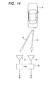
- reflected waves 33 from a target vehicle 19 are received by two receiving antennas 34 and a sum signal 36 and a differential signal 37 are first generated in a hybrid circuit 35.
- Fig. 15 shows the azimuthal characteristic 38 of the sum signal and the azimuthal characteristic 39 of the differential signal; and Fig.16 shows the azimuthal characteristic 40 as the ratio of sum signal to differential signal.
- the ratio of sum signal to differential signal is expressed by a monotonically decreasing function of azimuth, so that the azimuth can be uniquely determined based on the ratio of sum signal to differential signal, 40.
- a target can be identified, a plurality of targets scattered over a wide area can be detected accurately at the same time, leading to an excellent system response.
- One direction detection method other than the monopulse method is a beam switch method based on a plurality of beams each of which is assigned to each direction (direction cannot be detected by a single beam) where these beams are switched.
- Another method is a mechanical scanning method in which a beam is mechanically swung by a motor.
- the beam switch method has a problem that the use of a larger number of beams entails increase in size and cost and therefore is unsuitable as a means to widen the detection range.
- the direction resolution depends on beam sharpness and as the beam is sharper, the required antenna area is larger. Hence, a larger antenna must be used to achieve a higher resolution.
- Fig. 17 illustrates a conventional wide-angle radar.
- a millimeter-wave wide-angle radar 41 is installed on the front face of a mobile body 18 and a transmitted signal is emitted toward a target vehicle 19 from an antenna with a main lobe bb.
- the signal reflected by the target vehicle 19 is received by a receiving antenna which has almost the same detection angle range as the main lobe bb and the velocity and distance relative to the target vehicle 19 are calculated from the difference from the transmitted signal in terms of frequency, phase and time.
- Vtc ( V t ⁇ V m ) cos ⁇ 1
- Fig.18 is a spectral graph of a Doppler signal received by a radar in the monopulse method.
- the horizontal axis represents the relative velocity component of the target through a reflectedwave and the vertical axis represents received signal intensity.
- Noise level Ns for a radar-mounted vehicle at a stop depends on noise 22 generated in the radar's electronic circuit. Since the level of received signal 21 from the target with relative velocity component Vtc is represented by St, the SN ratio for the radar-mounted vehicle at a stop is expressed by (St-Ns). On the other hand, when a radar-mounted vehicle is running, the level of signal 23 from the roadside object suddenly increases in the range from relative velocity component V2a to V2b.
- the roadside object has a relative velocity during a run of the radar-mounted vehicle and a reflected wave is received as a signal.
- a rise in side lobes outside the main lobe is inevitable; therefore, there may be an unfavorable influence that the side lobes cause a rise in noise 42 in the relative velocity component range from 0 to V2a.
- the SN ratio which is expressed by (St - Nr) is lower than when it is not running, leading to reduction in the detection distance or misdetection.
- the monopulse method is excellent in direction resolution and permits a relatively compact design.
- the antenna beam width must be increased in order to broaden the detectable direction range as mentioned above, which may result in reduction in the detectable distance range and deterioration in direction resolution.
- the primary radiator is movable with respect to the focal plane as mentioned above and scanning is made with a single relatively narrow beam as used in the monopulse method, which broadens the overall detection range and eliminates the need for a larger system.
- the beam shape changes with direction and an adjustment is necessary for each scan.
- scanning is continuously made, the use of a reflected signal in the course of scanning for detection is unavoidable. Therefore, this means the need for continuous adjustments.
- the signal processing load for detection increases and the signal processing speed decreases, which might result in failure to achieve the system response indispensable for wide-angle detection.
- a system which uses a monopulse type antenna for each direction and provides a wider detection range by switching these antennas was considered prior to the present invention.
- the beam shape does not change with direction and a stationary antenna is used for detection, which means that the signal processing load is not so significant as mentioned above and the signal processing speed is higher.
- the system based on monopulse type beams enables direction identification within the detection range and thus the required number of antennas is remarkably decreased. Nevertheless, plural antennas are needed and increase in overall size is inevitable.
- An object of the present invention is to provide an automotive radar which processes signals at high speed to detect a target in a wide angle range.
- an automotive radar comprises: a transmitting antenna which emits an electromagnetic wave; at least two receiving antennas which receive the electromagnetic wave reflected by a target; an antenna plate on which the transmitting antenna and the at least two receiving antennas are arranged; a drive which, when the direction of arrangement of the at least two receiving antennas is an azimuth direction, rotates the antenna plate in the azimuth direction to scan a detection angle formed by the at least two receiving antennas, and provides rest time between scans to stop rotation; and a signal processor which detects the azimuth angle of a target with respect to a reference direction during the rest time according to received signals from the at least two receiving antennas and the rotation angle of the antenna plate at rest.
- the above automotive radar according to the present invention performs wide-angle detection by scanning a narrow detection angle. This excludes signals beyond the detection angle range. For example, right and left roadside objects can be isolated from a target on the road in terms of time.
- one antenna unit incorporating transmitting and receiving antennas is rotated, the beam shape does not change with direction; in addition, there is rest time in the course of scanning and signal processing is performed during the rest time, so no adjustment is needed in signal processing. Therefore, high speed signal processing can be performed to detect a target in a wide angle range.
- the system need not be large.
- Fig.1 is a block diagram showing the first embodiment of the present invention.
- a transmitting array antenna (transmitting antenna) 1 and receiving array antennas (receiving antennas) 2a and 2b are arranged on an antenna plate 3.
- a millimeter-wave signal generated by an oscillator 7 is sent through a power amplifier 6 to the transmitting array antenna 1.
- a transmitted signal as an electromagnetic wave from the transmitting array antenna 1 is reflected by a target (not shown) and the reflected signal is received by the receiving array antennas 2a and 2b, which then outputs received signals L and R.
- the received signals L and R enter mixers 8a and 8b respectively where they are mixed with an output signal from the oscillator 7 and converted into intermediate frequency signals.
- the intermediate frequency signals are amplified by low-noise amplifiers 9a and 9b before entering a signal processing circuit (DTM) 13.
- DTM signal processing circuit
- An azimuth motor 4 rotates the antenna plate 3 in the azimuth direction with the azimuth motor as a rotation axis within a prescribed angle range (approx. 80 degrees in the case shown in Fig . 1) to scan antenna detection angles for identifying the direction of the target in accordance with the monopulse method, in the order of na ⁇ nb ⁇ nc ⁇ nb ⁇ na ⁇ nd ⁇ ne ⁇ nd ⁇ na.
- ⁇ r represents a radar detection angle
- ⁇ m represents an antenna detection angle.
- a motor driver (DRA) 11 controls the azimuth motor 4 to stop the antenna plate 3 in detection angle positions na to ne momentarily. This rest time is determined depending on the processing capacity of the signal processing circuit 13.
- An antenna angle monitor (MRA) 12 monitors the rotation angle of the antenna plate 3, namely azimuth information, and sends it to the signal processing circuit 13.
- the azimuth information refers to a rotation angle with respect to a reference direction (direction of detection angle na in Fig .1, or mobile body running direction when the radar is mounted on a mobile body).
- the signal processing circuit 13 detects the azimuth angle of the target using the frequency-converted signal (from the received signal) and the azimuth information of the antenna plate 3. At the same time, it detects the relative velocity of the target and distance with respect to the radar-mounted vehicle. The result of detection is converted into a signal suitable for an output device such as a display unit (DPL) 14 as necessary and sent to the output device.
- the power amplifier 6, oscillator 7, mixers 8a and 8b, low-noise amplifiers 9a and 9b, motor driver 11, antenna angle monitor 12 and signal processing circuit 13 constitute a transmitter-receiver 10.
- the transmitting array antenna 1 and receiving array antennas 2a and 2b are covered by a domed radome 5 of dielectric material.
- the radome 5 does not rotate, or is fixed, and its front face is curved so that the distance between the front face and the receiving and transmitting antennas is almost constant. Due to this radome shape, during scanning, the beam shape remains virtually unchanged and is kept almost constant.
- the radome can be made with the same thickness on all the surfaces of the transmitting and receiving antennas. Since the radome is fixed onto the antenna plate 3, the weight of the rotating assembly increases accordingly but the beam shape is the same in all scanning positions.
- Fig.2 is a top view of the antennas used in this embodiment.
- a plurality of patch elements 15 and feeder wires 16 are formed on a dielectric substrate, constituting a transmitting antenna 1 and receiving array antennas 2a and 2b. Each array antenna lies on the antenna plate 3.
- the antennas used in this embodiment are of the flat type so a thinned radar is realized.
- Fig.3 shows that the radar 17 is installed on the front face of a mobile body 18 and detects a target vehicle 19 in the range of antenna detection angle nd at a certain time.
- Fig.4 is a spectral graph concerning a Doppler signal under this condition.
- St represents the level of a received signal 21 from the target 19 with relative velocity component Vtc. Since a signal from a roadside object 20 is not detected, noise level Nr depends on noise 22 generated in the radar's electronic circuit. Hence, SN ratio is expressed by (St-Nr).
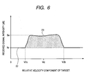
- Fig. 6 is a spectral graph concerning a Doppler signal under this condition.
- a received signal 23 from the roadside object has a relative velocity component range from V2a to V2b where Se represents signal level. Due to the narrow antenna detection angle, side lobes outside the main lobe can be reduced, which prevents noise rise in the relative velocity component range from 0 to V2a. Since a signal from the target vehicle 19 is not detected, noise level Nr depends on noise 22 generated in the radar's electronic circuit. Hence, SN ratio is expressed by (Se-Nr).
- the automotive radar in this embodiment performs wide-angle detection by scanning a narrow detection angle. This excludes signals beyond the detection angle range. For example, right and left roadside objects can be isolated from a target on the road in terms of time.
- one antenna unit incorporating transmitting and receiving antennas is rotated, the beam shape does not change with direction; in addition, there is rest time in the course of scanning and signal processing is performed during the rest time, so that no adjustment is needed in signal processing. Therefore, high speed signal processing can be performed to detect a target in a wide angle range.
- the system need not be large.
- scanning is made on an antenna detection angle for identifying the direction of a target in accordance with the monopulse method.
- This approach permits the use of a narrower scanning range than an example of the conventional mechanical scanning system where scanning is made on a beam which cannot identify a direction. This suggests improvement in response.
- the detection angle of a single receiving antenna can be narrower than in the conventional system where the detection angle is wide and no scanning is made. This leads to improvement in distance and direction detection accuracy.
- this embodiment employs a patch antenna
- a flat antenna like a slot antenna or triplate antenna may be used instead and the use of such an antenna can also lead to a thinned radar.
- a circulator may be used to enable one antenna to serve as both a transmitting and a receiving antenna, which can make the radar space saving.
- the power amplifier 6, oscillator 7, mixers 8a and 8b, and low-noise amplifiers 9a and 9b are arranged on the reverse side of the antenna plate 3, millimeter-waves can be transmitted with low loss.
- the system is designed to allow only the receiving array antennas 2a and 2b to rotate, high speed scanning is possible even when the azimuth motor 4 has a low torque.
- the antenna detection angle ⁇ m is increased while the radar detection angle ⁇ r is maintained, the overall rotation angle of the antenna plate 3 can be decreased, permitting higher speed scanning. Conversely, if the antenna detection angle ⁇ m is decreased, the distance detection accuracy and the direction detection accuracy can be improved. Also, if an antenna detection angle ⁇ m and a rest position are selected in a way for antenna detection angles to overlap, the accuracy of information on the target is improved and misdetection is prevented.
- This embodiment can provide a driver with optimum information which he/she wishes to know, by varying the mechanical scanning range according to running conditions including the radar-mounted vehicle's velocity, its velocity relative to a target, and intervehicle distance. Specifically, if the radar-mounted vehicle runs at high speed, it is particularly important to detect a target ahead and therefore any inf luence of unwanted reflected waves , etc. from the vicinity of the vehicle must be prevented. For that purpose, it is effective to narrow the mechanical scanning range. Alternatively, it is effective to emphasize scanning ahead the front face of the radar-mounted vehicle by decreasing the interval between antenna detection angles ahead of the radar-mounted vehicle front face or other means.
- the vehicle runs slowly, it is effective to widen the mechanical scanning range because a target in the vicinity of the vehicle must be detected. Alternatively, it is effective to scan over a wider range by increasing the interval between antenna detection angles ahead of the radar-mounted vehicle front face or other means. The same is true of the relative velocity and the space between the radar-mounted vehicle and the target.
- the steering wheel, etc. of the radar-mounted vehicle may be interlinked with switching of the mechanical scanning range.
- Fig.7A is a block diagram showing a second embodiment of the present invention.
- a detection distance controller (CNT) 24 which controls the detection distance at antenna angle na is provided in addition to the same components as those of the first embodiment.
- the transmitting array antenna 1 and receiving array antennas 2a and 2b are arranged on the antenna plate 3.
- a millimeter-wave signal generated by the oscillator 7 is sent through a variable gain amplifier 25 to the transmitting array antenna 1.
- a transmitted signal emitted from the transmitting array antenna 1 is reflected by a target and the reflected signal is received by the receiving array antennas 2a and 2b.
- the received signals L and R enter the mixers 8a and 8b respectively where they are mixed with an output signal from the oscillator 7 and converted into intermediate frequency signals.
- the intermediate frequency signals are amplified by low-noise variable gain amplifiers 26a and 26b before entering the signal processing circuit (DTM) 13.
- the azimuth motor 4 rotates the antenna plate 3 to scan antenna detection angles for identifying the direction of the target in accordance with the monopulse method, in the order of na ⁇ nb ⁇ nc ⁇ nb ⁇ na ⁇ nd ⁇ ne ⁇ nd ⁇ na.
- the motor driver 11 controls the azimuth motor 4 to stop the antenna plate 3 in detection angle positions na to ne momentarily. This rest time depends on the processing capacity of the signal processing circuit.
- the antenna angle monitor 12 monitors the rotation angle of the antenna plate 3, namely azimuth information, and sends it to the signal processing circuit 13.
- the signal processing circuit 13 detects the azimuth angle of the target using the frequency-converted signal (from the received signal) and the azimuth information of the antenna plate 3. At the same time, it detects the relative velocity and the distance between the radar-mounted vehicle and the target. The result of detection is converted into a signal suitable for an output device such as a display unit 14 as necessary and sent to the output device.
- the detection distance controller (CNT) 24 receives an instruction signal from the antenna angle monitor 12 and increases the gain of at least either the variable gain amplifier 25 or the low noise variable gain amplifiers 26a, 26b in detection angle na than in detection angles nb tone. This makes it possible to detect a remote target.
- the transmitting array antenna 1 and receiving array antennas 2a and 2b are covered by a radome 5 of dielectric material.
- the automotive radar in the second embodiment performs wide-angle detection by scanning a narrow detection angle. This excludes signals beyond the detection angle range. For example, right and left roadside objects can be isolated from the target on the road in terms of time.
- Fig.7B shows that each common antenna serves as both a transmitting antenna and a receiving antenna through the use of a circulator according to this embodiment.
- 101a and 101b represent common antennas which each serve as both a transmitting antenna and a receiving antenna;
- 102a and 102b represent circulators which are connected with the common antennas 101a and 101b respectively.
- the circulators 102a and 102b switch the transmission mode to the reception mode and vice versa.
- the use of such dual-purpose common antennas permits a space-saving radar design.
- Such dual-purpose common antennas may also be used similarly in other embodiments.
- Fig.8 illustrates an application example of this embodiment.
- a narrow-angle/long-distance radar for adaptive cruise control (ACC) should be mounted on the front face of the vehicle and wide-angle/short-distance radars for collision detection should be mounted on the front, side and rear faces of the vehicle.
- ACC adaptive cruise control
- the use of several radars leads to a higher cost.
- a low cost radar system which combines a narrow-angle/long-distance detection function and a wide-angle/short-distance detection function.
- the application example as shown in Fig. 8 is designed to meet this demand.
- a radar 27 is mounted on the front face of the mobile body 18 so as to cover a long distance in the frontal direction and short distances in oblique directions ahead.
- side sensors 28a and 28b as conventional wide-angle radars are mounted on side faces of the mobile body 18 with wide-angle/short-distance detection ranges bx and by respectively.
- a rear sensor 29 is mounted on the back of the mobile body 18 with awide-angle/short-distance detection range bz. The consequence is a low cost radar system that performs 360-degree detection around the mobile body with a minimal number of radars for increased safety.
- Fig.9 is a block diagram showing a third embodiment of the present invention.
- an elevation angle motor 30 which rotates an antenna in the direction of elevation angle (angle perpendicular to the road surface) is provided in addition to the same components as those of the first embodiment.
- the transmitting array antenna 1 and receiving array antennas 2a and 2b are arranged on the antenna plate 3.
- a millimeter-wave signal generated by the oscillator 7 is sent through the power amplifier 6 to the transmitting array antenna 1.
- a signal emitted from the transmitting array antenna 1 is reflected by the target and the reflected signal is received by the receiving array antennas 2a and 2b.
- the received signals L and R enter the mixers 8a and 8b respectively where they are mixed with an output signal from the oscillator 7 and converted into intermediate frequency signals.
- the intermediate frequency signals are amplified by the low-noise amplifiers 9a and 9b before entering the signal processing circuit (DTM) 13.
- the azimuth motor 4 rotates the antenna plate 3 to scan antenna detection angles for identifying the direction of the target in accordance with the monopulse method, in the order of na ⁇ nb ⁇ nc ⁇ nb ⁇ na ⁇ nd ⁇ ne ⁇ nd ⁇ na.
- the elevation angle motor 30 rotates the antenna plate 3 in the direction of elevation angle.
- the motor driver 11 controls the azimuth motor 4 and the elevation angle motor 30 to stop rotation of the antenna plate 3 in the azimuth and elevation angle directions momentarily. This rest time is determined depending on the processing capacity of the signal processing circuit and signal processing is performed while scanning is made neither in the azimuth direction nor in the elevation angle direction.
- the antenna angle monitor 12 monitors the azimuth angle and elevation angle of the antenna plate 3 and sends azimuth and elevation angle information to the signal processing circuit 13. While the antenna plate 3 is still, the signal processing circuit 13 detects the position of the target using the frequency-converted signal (from the received signal) and the azimuth and elevation angle information of the antenna plate 3. At the same time, it detects the relative velocity and the distance between the radar-mounted vehicle and the target. The result of detection is converted into a signal suitable for an output device such as a display unit 14 as necessary and sent to the output device.
- the transmitting array antenna 1 and receiving array antennas 2a and 2b are covered by a radome 5 of dielectric material.
- Fig.10 illustrates how scanning in the direction of elevation angle is made according to this embodiment.
- the radar 31 is mounted on the front face of the mobile body 18.
- the elevation angle motor 30 rotates the antenna plate 3 to scan antenna detection angles for identifying the direction of the target in accordance with the monopulse method, in the order of ea ⁇ eb ⁇ ec ⁇ eb ⁇ ea ⁇ ed ⁇ ea.
- a target can be isolated in the height direction easily, so that a tunnel or an iron bridge can be recognized. Even when the vehicle is running on a sloping road, the system does not fail to detect a target.
- the automotive radar in this embodiment performs wide-angle detection by scanning a narrow detection angle. This excludes signals beyond the detection angle range. For example, right and left roadside objects can be isolated from a target on the road in terms of time.
- one antenna unit incorporating transmitting and receiving antennas is rotated, the beam shape does not change with direction; in addition, there is rest time in the course of scanning and signal processing is performed during the rest time, so that no adjustment is needed in signal processing. Therefore, high speed signal processing can be performed to detect a target in a wide angle range.
- the system need not be large.
- scanning is made on an antenna detection angle for identifying the direction of a target in accordance with the monopulse method.
- This approach permits the use of a narrower scanning range than an example of the conventional mechanical scanning system where scanning is made on a beam which cannot identify a direction. This suggests improvement in response.
- the detection angle of a single receiving antenna can be narrower than in the conventional system where the detection angle is wide and no scanning is made. This leads to improvement in distance and direction detection accuracy.
- the azimuth motor 4 may be omitted.
- Fig.11 is a block diagram showing a fourth embodiment of the present invention.
- receiving array antennas 2c and 2d and various circuits connected with them are provided in addition to the same components as those of the third embodiment.
- the transmitting array antenna 1 and receiving array antennas 2a to 2d are arranged on the antenna plate 3.
- a millimeter-wave signal generated by the oscillator 7 is sent through the power amplifier 6 to the transmitting array antenna 1.
- a signal emitted from the transmitting array antenna 1 is reflected by a target and the reflected signal is received by the receiving array antennas 2a to 2d.
- the receiving array antennas 2a to 2d output received signals TL, TR, BL and BR respectively.
- the received signals TL, TR, BL and BR enter the mixers 8a to 8d respectively where they are mixed with an output signal from the oscillator 7 and converted into intermediate frequency signals.
- the intermediate frequency signals are amplified by the low-noise amplifiers 9a to 9d before entering the signal processing circuit 13.
- Fig. 12 is a top view of antennas used in this embodiment.
- a plurality of patch elements 15 and feeder wires 16 are formed on a dielectric substrate, constituting a transmitting array antenna 1 and receiving array antennas 2a to 2d.
- the four receiving antennas 2a to 2d are adjacent to each other horizontally and vertically.
- the array antennas lie on the antenna plate 3.
- the antennas used in this embodiment are of the flat type so a thinned radar is realized.
- the azimuth angle of the target with respect to the frontal direction of the antenna plate 3 can be identified according to amplitude or phase difference in received signals TL and TR from the antennas 2a and 2b, aligned horizontally in Fig. 12. Needless to say, it is possible to identify the azimuth angle of the target by comparison between received signals BL and BR or by comparison between the sums of received signals (TL + BL) and (TR + BR).
- the elevation angle of the target with respect to the frontal direction of the antenna plate 3 can be identified according to amplitude or phase difference in received signals TL and BL from the antennas 2a and 2c, aligned vertically.
- the elevation angle of the target can be identified by comparison between received signals TR and BR or by comparison between the sums of received signals (TL + BL) and (TR + BR).
- the azimuth motor 4 rotates the antenna plate 3 to scan antenna detection angles for identifying the direction of the target in accordance with the monopulse method, in the order of na ⁇ nb ⁇ nc ⁇ nb ⁇ na ⁇ nd ⁇ ne ⁇ nd ⁇ na.
- the elevation angle motor 30 rotates the antenna plate 3 in the direction of elevation angle.
- the motor driver 11 controls the azimuth motor 4 and the elevation angle motor 30 to stop rotation of the antenna plate 3 in each antenna azimuth position momentarily. This rest time depends on the processing capacity of the signal processing circuit.
- the antenna angle monitor 12 monitors the azimuth angle and elevation angle of the antenna plate 3 and sends azimuth and elevation angle information to the signal processing circuit 13. While the antenna plate 3 is still, the signal processing circuit 13 detects the position of the target using the frequency-converted signal (from the received signal) and the azimuth and elevation angle information of the antenna plate 3. At the same time, it detects the relative velocity and the distance between the radar-mounted vehicle and the target. The result of detection is converted into a signal suitable for an output device such as a display unit 14 as necessary and sent to the output device.
- the transmitting array antenna 1 and receiving array antennas 2a and 2b are covered by a radome 5 of dielectric material.
- Fig.13 illustrates how scanning in the direction of elevation angle is made according to this embodiment.
- the radar 31 is mounted on the front face of the mobile body 18.
- the elevation angle motor rotates the antenna plate to scan antenna detection angles for identifying the azimuth and elevation angles of the target in accordance with the monopulse method, in the order of fa ⁇ fb ⁇ fc ⁇ fb ⁇ fa ⁇ fd ⁇ fa. Therefore, according to this embodiment, a target can be isolated in the height direction accurately, so that a tunnel or an iron bridge can be recognized. Even when the vehicle is running on a sloping road, the system does not fail to detect a target.
- the automotive radar in this embodiment performs wide-angle detection by scanning a narrow detection angle. This excludes signals beyond the detection angle range. For example, right and left roadside objects can be isolated from a target on the road in terms of time.
- one antenna unit incorporating transmitting and receiving antennas is rotated, the beam shape does not change with direction; in addition, there is rest time in the course of scanning, and signal processing is performed during the rest time, so that no adjustment is needed in signal processing. Therefore, high speed signal processing can be performed to detect a target in a wide angle range.
- the system need not be large.
- scanning is made on an antenna detection angle for identifying the direction of a target in accordance with the monopulse method.
- This approach permits the use of a narrower scanning range than an example of the conventional mechanical scanning system where scanning is made on a beam which cannot identify a direction. This suggests improvement in response.
- the detection angle of a single receiving antenna can be narrower than in the conventional system where the detection angle is wide and no scanning is made. This leads to improvement in distance and direction detection accuracy.
- this embodiment employs a patch antenna
- a flat antenna like a slot antenna or triplate antenna may be used instead and the use of such an antenna can also lead to a thinned radar.
- a single antenna unit in scanning a narrow detection angle for wide-angle detection, a single antenna unit is rotated and there is rest time during scanning so that no adjustment is necessary in signal processing and therefore high speed signal processing can be performed to detect a target in a wide angle range.
Landscapes
- Engineering & Computer Science (AREA)
- Radar, Positioning & Navigation (AREA)
- Remote Sensing (AREA)
- Physics & Mathematics (AREA)
- Computer Networks & Wireless Communication (AREA)
- General Physics & Mathematics (AREA)
- Electromagnetism (AREA)
- Radar Systems Or Details Thereof (AREA)
- Variable-Direction Aerials And Aerial Arrays (AREA)
Applications Claiming Priority (1)
| Application Number | Priority Date | Filing Date | Title |
|---|---|---|---|
| JP2005012460A JP2006201013A (ja) | 2005-01-20 | 2005-01-20 | 車載用レーダ |
Publications (1)
| Publication Number | Publication Date |
|---|---|
| EP1684092A1 true EP1684092A1 (en) | 2006-07-26 |
Family
ID=36390259
Family Applications (1)
| Application Number | Title | Priority Date | Filing Date |
|---|---|---|---|
| EP05018190A Withdrawn EP1684092A1 (en) | 2005-01-20 | 2005-08-22 | Automotive radar with mechanically scanned monopulse antenna |
Country Status (4)
| Country | Link |
|---|---|
| US (1) | US7132976B2 (https=) |
| EP (1) | EP1684092A1 (https=) |
| JP (1) | JP2006201013A (https=) |
| CN (1) | CN1808177A (https=) |
Cited By (10)
| Publication number | Priority date | Publication date | Assignee | Title |
|---|---|---|---|---|
| EP1837679A1 (en) * | 2006-03-23 | 2007-09-26 | Omron Corporation | Radar device and radar method |
| WO2009065651A1 (de) * | 2007-11-22 | 2009-05-28 | Robert Bosch Gmbh | Winkelauflösender radarsensor |
| DE102008052246A1 (de) * | 2008-10-18 | 2010-04-22 | Adc Automotive Distance Control Systems Gmbh | Sensorsystem mit verstellbarer Elevationsstrahlrichtung zur Bestimmung der vertikalen Lage von stationären Objekten |
| DE102009057032A1 (de) * | 2009-12-04 | 2011-06-09 | Bayerische Motoren Werke Aktiengesellschaft | Verfahren und Vorrichtung zur radargestützten Steuerung einer Funktion eines Fahrzeugs |
| US9784831B2 (en) | 2014-08-20 | 2017-10-10 | Wistron Neweb Corporation | Pre-warning method and vehicle radar system |
| US9994152B1 (en) | 2015-08-07 | 2018-06-12 | Ryan Hess | Active scanning collision avoidance system |
| US10162052B2 (en) | 2014-08-20 | 2018-12-25 | Wistron Neweb Corporation | Pre-warning method and vehicle radar system |
| WO2020089233A1 (de) * | 2018-10-30 | 2020-05-07 | Continental Automotive Gmbh | Doppler-radar-sensorvorrichtung an einem fahrzeugelement mit durch einen aktor eigenbewegten antenne zur detektion statischer objekte |
| CN112363116A (zh) * | 2020-11-28 | 2021-02-12 | 南京誉葆科技有限公司 | 一种毫米波收发系统 |
| US20210325524A1 (en) * | 2019-01-31 | 2021-10-21 | Mitsubishi Electric Corporation | Angle measuring device, angle measuring method, and in-vehicle device |
Families Citing this family (96)
| Publication number | Priority date | Publication date | Assignee | Title |
|---|---|---|---|---|
| US6982670B2 (en) * | 2003-06-04 | 2006-01-03 | Farrokh Mohamadi | Phase management for beam-forming applications |
| US7432855B2 (en) * | 2004-06-03 | 2008-10-07 | Farrokh Mohamadi | RFID reader and active tag |
| US7437232B2 (en) * | 2005-03-31 | 2008-10-14 | Nissan Technical Center North America, Inc. | Vehicle and method for speed control based on position information of other vehicles |
| CN101185009B (zh) * | 2005-06-15 | 2011-12-07 | 株式会社村田制作所 | 雷达装置 |
| JP2007116217A (ja) * | 2005-10-18 | 2007-05-10 | Hitachi Ltd | ミリ波レーダ装置およびそれを用いたミリ波レーダシステム |
| JP4304517B2 (ja) * | 2005-11-09 | 2009-07-29 | トヨタ自動車株式会社 | 物体検出装置 |
| US20080088499A1 (en) * | 2006-05-24 | 2008-04-17 | Bonthron Andrew J | Methods and apparatus for hyperview automotive radar |
| JP5042558B2 (ja) * | 2006-08-10 | 2012-10-03 | 富士通テン株式会社 | レーダ装置 |
| JP4769684B2 (ja) * | 2006-10-12 | 2011-09-07 | 株式会社デンソーアイティーラボラトリ | 電子走査式レーダ装置 |
| JP5176314B2 (ja) * | 2006-12-15 | 2013-04-03 | 株式会社デンソー | レーダ装置 |
| JP5160114B2 (ja) * | 2007-03-26 | 2013-03-13 | 本田技研工業株式会社 | 車両の通り抜け判断装置 |
| DE102007046648A1 (de) * | 2007-09-28 | 2009-04-02 | Robert Bosch Gmbh | Radarsensor zur Erfassung des Verkehrsumfelds in Kraftfahrzeugen |
| JP2009265007A (ja) * | 2008-04-28 | 2009-11-12 | Hitachi Ltd | 移動体用レーダ及び平面アンテナ |
| DE102008038365A1 (de) | 2008-07-02 | 2010-01-07 | Adc Automotive Distance Control Systems Gmbh | Fahrzeug-Radarsystem und Verfahren zur Bestimmung einer Position zumindest eines Objekts relativ zu einem Fahrzeug |
| US8344940B2 (en) * | 2009-01-22 | 2013-01-01 | Mando Corporation | Apparatus and sensor for adjusting sensor vertical alignment |
| CN102301405B (zh) * | 2009-01-29 | 2014-01-15 | 丰田自动车株式会社 | 物体识别装置以及物体识别方法 |
| JP5558342B2 (ja) * | 2009-02-27 | 2014-07-23 | トヨタ自動車株式会社 | 車載レーダー装置および車載レーダー装置用カバー |
| JP5071414B2 (ja) * | 2009-03-04 | 2012-11-14 | 株式会社デンソー | レーダ装置 |
| JP2010204030A (ja) * | 2009-03-05 | 2010-09-16 | Fuji Heavy Ind Ltd | 車載レーダ用アンテナ |
| EP2629113B1 (de) | 2009-04-06 | 2017-04-26 | Conti Temic microelectronic GmbH | Radarsystem mit anordnungen und verfahren zur entkopplung von sende- und empfangssignalen sowie unterdrückung von störeinstrahlungen |
| JP4790045B2 (ja) * | 2009-05-19 | 2011-10-12 | 本田技研工業株式会社 | レーダの軸ずれを判定する装置 |
| JP5418770B2 (ja) * | 2009-07-29 | 2014-02-19 | トヨタ自動車株式会社 | レーダ装置 |
| DE112009005400B4 (de) * | 2009-11-27 | 2015-05-13 | Toyota Jidosha Kabushiki Kaisha | Kollisionsvermeidungsvorrichtung |
| KR101137038B1 (ko) * | 2010-01-05 | 2012-04-19 | 주식회사 만도 | 레이더 장치, 안테나 장치 및 데이터 획득 방법 |
| WO2011092814A1 (ja) * | 2010-01-28 | 2011-08-04 | トヨタ自動車株式会社 | 障害物検出装置 |
| DE102010012626A1 (de) * | 2010-03-24 | 2011-09-29 | Valeo Schalter Und Sensoren Gmbh | Kraftfahrzeug mit einer Radareinrichtung und Verfahren zum Betreiben einer Radareinrichtung |
| KR20110126939A (ko) * | 2010-05-18 | 2011-11-24 | 주식회사 만도 | 통합 레이더 시스템 및 차량 제어 시스템 |
| JP5093298B2 (ja) * | 2010-06-04 | 2012-12-12 | 株式会社デンソー | 方位検出装置 |
| DE102010038517A1 (de) * | 2010-07-28 | 2012-02-02 | Robert Bosch Gmbh | Radom für einen Radarsensor in einem Kraftfahrzeug und entsprechender Radarsensor |
| US8736484B2 (en) * | 2010-08-11 | 2014-05-27 | Lockheed Martin Corporation | Enhanced-resolution phased array radar |
| US8405245B1 (en) | 2010-09-09 | 2013-03-26 | II Jimmy Ray Clay | Emergency response steering wheel device |
| CN102004246B (zh) * | 2010-09-10 | 2012-08-15 | 浙江大学 | 列车车载雷达速度传感器天线夹角偏差故障诊断及速度读数校正方法 |
| JP5610983B2 (ja) * | 2010-11-01 | 2014-10-22 | 三菱電機株式会社 | レーダ装置 |
| DE102012102185A1 (de) * | 2011-03-16 | 2012-09-27 | Electronics And Telecommunications Research Institute | Radarvorrichtung, die den kurz- und langreichweitigen Radarbetrieb unterstützt |
| JP5472187B2 (ja) * | 2011-04-06 | 2014-04-16 | 株式会社デンソー | アンテナ装置 |
| DE102011078641A1 (de) * | 2011-07-05 | 2013-01-10 | Robert Bosch Gmbh | Radarsystem für Kraftfahrzeuge sowie Kraftfahrzeug mit einem Radarsystem |
| US8441394B2 (en) * | 2011-07-11 | 2013-05-14 | Delphi Technologies, Inc. | System and method for detecting obstructions and misalignment of ground vehicle radar systems |
| US20130088393A1 (en) * | 2011-10-06 | 2013-04-11 | Toyota Motor Engineering & Manufacturing North America, Inc. | Transmit and receive phased array for automotive radar improvement |
| DE102012204267A1 (de) * | 2012-03-19 | 2013-09-19 | Robert Bosch Gmbh | Sensorhalterung für einen Sensor zur Objektdetektion |
| US9274222B1 (en) * | 2013-03-04 | 2016-03-01 | Toyota Motor Engineering & Manufacturing North America, Inc. | Dynamic allocation of radar beams in automotive environments with phased array radar |
| KR20180059963A (ko) * | 2013-03-15 | 2018-06-05 | 오토리브 에이에스피, 인크. | 사각지대 검출 기능을 갖춘 차량 레이더 시스템 |
| JP2014182023A (ja) * | 2013-03-19 | 2014-09-29 | National Univ Corp Shizuoka Univ | 車載用のレーダ装置 |
| JP6175863B2 (ja) * | 2013-03-29 | 2017-08-09 | 富士通株式会社 | レーダ装置及びプログラム |
| DE102013216970A1 (de) * | 2013-08-27 | 2015-03-05 | Robert Bosch Gmbh | Radarsensor für Kraftfahrzeuge |
| CN103675802B (zh) * | 2013-12-18 | 2017-06-09 | 张鹿平 | 用双路馈线实现大功率雷达近距离探测的系统及方法 |
| JP2015141041A (ja) * | 2014-01-27 | 2015-08-03 | 三菱電機株式会社 | アンテナ装置 |
| US9541639B2 (en) * | 2014-03-05 | 2017-01-10 | Delphi Technologies, Inc. | MIMO antenna with elevation detection |
| JP2015172491A (ja) * | 2014-03-11 | 2015-10-01 | 富士通テン株式会社 | アンテナ、レーダ装置、および、車両制御システム |
| KR102173994B1 (ko) * | 2014-03-18 | 2020-11-04 | 주식회사 만도 | 차량용 레이더의 조정 방법 및 제어 장치 |
| US10069200B2 (en) | 2014-03-19 | 2018-09-04 | Insitu, Inc. | Mechanically steered and horizontally polarized antenna for aerial vehicles, and associated systems and methods |
| US20160047907A1 (en) * | 2014-08-14 | 2016-02-18 | Google Inc. | Modular Planar Multi-Sector 90 Degrees FOV Radar Antenna Architecture |
| CA2884808C (en) * | 2014-09-01 | 2019-05-07 | Komatsu Ltd. | Transporter vehicle and transporter vehicle control method |
| JP6498931B2 (ja) * | 2014-12-25 | 2019-04-10 | 株式会社Soken | レーダ装置、及びカバー部材 |
| KR20170011882A (ko) * | 2015-07-24 | 2017-02-02 | 엘지전자 주식회사 | 차량용 레이더, 및 이를 구비하는 차량 |
| KR20170011881A (ko) * | 2015-07-24 | 2017-02-02 | 엘지전자 주식회사 | 차량용 레이더, 및 이를 구비하는 차량 |
| DE102015222884A1 (de) | 2015-11-19 | 2017-05-24 | Conti Temic Microelectronic Gmbh | Radarsystem mit verschachtelt seriellem Senden und parallelem Empfangen |
| KR101890352B1 (ko) * | 2015-12-11 | 2018-08-21 | 주식회사 만도 | 차량용 레이더 장치 및 그의 고스트 제거 방법 |
| WO2017170979A1 (ja) * | 2016-03-31 | 2017-10-05 | 古河電気工業株式会社 | 監視装置および監視方法 |
| IL246386B (en) * | 2016-06-22 | 2018-03-29 | Tarantula Tech Ltd | A device for identifying dangerous objects located at a certain distance from a surface |
| CN109791198B (zh) | 2016-08-15 | 2023-08-15 | 代表亚利桑那大学的亚利桑那校董会 | 使用3d打印伦伯透镜的新颖汽车雷达 |
| US10620298B2 (en) * | 2016-08-26 | 2020-04-14 | Infineon Technologies Ag | Receive chain configuration for concurrent multi-mode radar operation |
| EP3293543B1 (en) * | 2016-09-08 | 2021-06-09 | KNORR-BREMSE Systeme für Nutzfahrzeuge GmbH | Apparatus for sensing a vehicular environment when fitted to a vehicle |
| JP6723133B2 (ja) * | 2016-10-04 | 2020-07-15 | 日立オートモティブシステムズ株式会社 | アンテナ、センサ及び車載システム |
| CN106707297B (zh) * | 2016-11-08 | 2023-09-01 | 上海禾赛科技有限公司 | 大视场车载激光雷达及车辆 |
| WO2018133066A1 (zh) | 2017-01-22 | 2018-07-26 | 深圳市大疆创新科技有限公司 | 二维天线系统、用于定位目标的方法和设备 |
| JP6508243B2 (ja) * | 2017-03-30 | 2019-05-08 | トヨタ自動車株式会社 | 車載ミリ波通信装置および通信方法 |
| US10129763B1 (en) * | 2017-04-04 | 2018-11-13 | Sprint Spectrum L.P. | Method and system for controlling radio frequency interference to public safety communication |
| US10495730B1 (en) * | 2017-04-13 | 2019-12-03 | L-3 Communications Corp. | Phase agnostic monopulse tracking |
| CN108521792A (zh) * | 2017-04-27 | 2018-09-11 | 深圳市大疆创新科技有限公司 | 微波雷达的测距方法、微波雷达、计算机存储介质、无人飞行器及其控制方法 |
| US10797807B2 (en) * | 2017-09-20 | 2020-10-06 | Commscope Technologies Llc | Methods for calibrating millimeter wave antenna arrays |
| EP3490062B1 (en) * | 2017-11-27 | 2022-07-27 | Panasonic Intellectual Property Management Co., Ltd. | Radar device |
| US10985471B2 (en) * | 2017-11-27 | 2021-04-20 | Panasonic Intellectual Property Management Co., Ltd. | Radar device |
| CN109849782A (zh) * | 2017-11-30 | 2019-06-07 | 比亚迪股份有限公司 | 虚拟全景辅助驾驶装置及其显示方法、车辆 |
| CN111801592B (zh) * | 2018-01-04 | 2025-01-21 | 谷鲁股份有限公司 | 使用微波和毫米波视差对空间的三维和四维测绘 |
| US11002828B2 (en) * | 2018-01-12 | 2021-05-11 | Tiejun Shan | Method of using a multi-input and multi-output antenna (MIMO) array for high-resolution radar imaging and wireless communication for advanced driver assistance systems (ADAS) and autonomous driving |
| JP6975261B2 (ja) * | 2018-01-30 | 2021-12-01 | 古野電気株式会社 | レーダアンテナ装置及び方位測定方法 |
| CN108415000B (zh) * | 2018-02-09 | 2021-10-12 | 山东国耀量子雷达科技有限公司 | 一种基于多关节机械臂的激光雷达 |
| CN108196255A (zh) * | 2018-03-23 | 2018-06-22 | 加特兰微电子科技(上海)有限公司 | 一种车用毫米波雷达系统 |
| JP7061534B2 (ja) * | 2018-08-02 | 2022-04-28 | 日立Astemo株式会社 | レーダ装置 |
| JP7099180B2 (ja) * | 2018-08-28 | 2022-07-12 | トヨタ自動車株式会社 | 周辺情報検出センサの配設構造 |
| EP3862785A4 (en) * | 2018-10-05 | 2022-07-06 | Kyocera Corporation | Electronic device, electronic device control method, and electronic device control program |
| DE102018218253A1 (de) * | 2018-10-25 | 2020-04-30 | Robert Bosch Gmbh | Radarsensor |
| US12158516B2 (en) * | 2018-11-14 | 2024-12-03 | Sony Group Corporation | Control device, control method and sensor control system |
| CN109765563B (zh) * | 2019-01-15 | 2021-06-11 | 北京百度网讯科技有限公司 | 一种超声波雷达阵列、障碍物检测方法及系统 |
| US12140692B2 (en) * | 2019-01-31 | 2024-11-12 | Mitsubishi Electric Corporation | Antenna device and radar apparatus |
| KR102814886B1 (ko) * | 2019-03-11 | 2025-05-30 | 주식회사 에이치엘클레무브 | 레이더 장치, 레이더 장치용 안테나 장치 및 레이더 장치의 제어 방법 |
| US12055626B2 (en) | 2019-08-05 | 2024-08-06 | Koito Manufacturing Co., Ltd. | Vehicle lamp and vehicle |
| CN112389315A (zh) * | 2019-08-15 | 2021-02-23 | 株式会社小糸制作所 | 车辆用灯具及车辆 |
| WO2021070762A1 (ja) * | 2019-10-10 | 2021-04-15 | 京セラ株式会社 | 電子機器、電子機器の制御方法、及び電子機器の制御プログラム |
| US10832570B1 (en) * | 2019-12-20 | 2020-11-10 | Ford Global Technologies, Llc | V2X vehicle road usage |
| US11351961B2 (en) * | 2020-01-29 | 2022-06-07 | Ford Global Technologies, Llc | Proximity-based vehicle security systems and methods |
| US12216225B2 (en) * | 2020-12-08 | 2025-02-04 | Aptiv Technologies AG | Facia supporting an ultra-wide radar field-of-view |
| JP7504784B2 (ja) * | 2020-12-10 | 2024-06-24 | 株式会社東芝 | 検査システム及び検査方法 |
| DE112021006960T5 (de) * | 2021-01-28 | 2023-12-14 | Keysight Technologies Inc. | System und verfahren zum emulieren von echosignalen von emulierten zielen mit reduzierter störung durch reflexion |
| JP7501512B2 (ja) * | 2021-12-09 | 2024-06-18 | 株式会社デンソー | レーダシステム |
| CN115184875A (zh) * | 2022-08-23 | 2022-10-14 | 清华大学 | 车载雷达的探测方法及车载雷达 |
Citations (9)
| Publication number | Priority date | Publication date | Assignee | Title |
|---|---|---|---|---|
| DE2147523A1 (de) * | 1971-09-23 | 1973-03-29 | Licentia Gmbh | Verfahren zum vermindern der kollisionsgefaehrdung eines strassenfahrzeuges und radargeraet zur durchfuehrung des verfahrens |
| US3953857A (en) * | 1972-03-07 | 1976-04-27 | Jenks Frederic A | Airborne multi-mode radiating and receiving system |
| US3987451A (en) * | 1975-02-07 | 1976-10-19 | Texas Instruments Incorporated | Beam type planar array antenna system |
| US5926128A (en) * | 1972-11-01 | 1999-07-20 | The Marconi Company Limited | Radar systems |
| JP2000022423A (ja) | 1998-07-03 | 2000-01-21 | Murata Mfg Co Ltd | アンテナ装置および送受信装置 |
| US6085151A (en) * | 1998-01-20 | 2000-07-04 | Automotive Systems Laboratory, Inc. | Predictive collision sensing system |
| US6169518B1 (en) * | 1980-06-12 | 2001-01-02 | Raytheon Company | Dual beam monopulse antenna system |
| US6243052B1 (en) | 1999-11-16 | 2001-06-05 | Harris Corporation | Low profile panel-configured helical phased array antenna with pseudo-monopulse beam-control subsystem |
| EP1391748A1 (en) * | 2001-05-30 | 2004-02-25 | Hitachi, Ltd. | Radar device |
Family Cites Families (6)
| Publication number | Priority date | Publication date | Assignee | Title |
|---|---|---|---|---|
| US3935559A (en) * | 1973-05-31 | 1976-01-27 | Electronic Machine Control (Sales) Limited | Transporter systems |
| US3886555A (en) * | 1973-06-04 | 1975-05-27 | Trw Inc | Radiating target direction finding system |
| JP3398745B2 (ja) * | 1997-08-21 | 2003-04-21 | 三菱電機株式会社 | 車載用レーダ装置 |
| JPH11264871A (ja) * | 1998-03-17 | 1999-09-28 | Komatsu Ltd | 車両用障害物検出装置の監視機構 |
| JP2002353712A (ja) * | 2001-05-24 | 2002-12-06 | Mitsubishi Electric Corp | 車両周辺監視装置 |
| FR2834110B1 (fr) * | 2001-12-20 | 2004-01-30 | Valeo Vision | Dispositif d'aide a la conduite pour vehicule automobile optimise par synergie avec un eclairage adaptatif |
-
2005
- 2005-01-20 JP JP2005012460A patent/JP2006201013A/ja not_active Withdrawn
- 2005-08-19 US US11/206,765 patent/US7132976B2/en not_active Expired - Fee Related
- 2005-08-22 EP EP05018190A patent/EP1684092A1/en not_active Withdrawn
- 2005-08-22 CN CNA2005100924693A patent/CN1808177A/zh active Pending
Patent Citations (9)
| Publication number | Priority date | Publication date | Assignee | Title |
|---|---|---|---|---|
| DE2147523A1 (de) * | 1971-09-23 | 1973-03-29 | Licentia Gmbh | Verfahren zum vermindern der kollisionsgefaehrdung eines strassenfahrzeuges und radargeraet zur durchfuehrung des verfahrens |
| US3953857A (en) * | 1972-03-07 | 1976-04-27 | Jenks Frederic A | Airborne multi-mode radiating and receiving system |
| US5926128A (en) * | 1972-11-01 | 1999-07-20 | The Marconi Company Limited | Radar systems |
| US3987451A (en) * | 1975-02-07 | 1976-10-19 | Texas Instruments Incorporated | Beam type planar array antenna system |
| US6169518B1 (en) * | 1980-06-12 | 2001-01-02 | Raytheon Company | Dual beam monopulse antenna system |
| US6085151A (en) * | 1998-01-20 | 2000-07-04 | Automotive Systems Laboratory, Inc. | Predictive collision sensing system |
| JP2000022423A (ja) | 1998-07-03 | 2000-01-21 | Murata Mfg Co Ltd | アンテナ装置および送受信装置 |
| US6243052B1 (en) | 1999-11-16 | 2001-06-05 | Harris Corporation | Low profile panel-configured helical phased array antenna with pseudo-monopulse beam-control subsystem |
| EP1391748A1 (en) * | 2001-05-30 | 2004-02-25 | Hitachi, Ltd. | Radar device |
Non-Patent Citations (2)
| Title |
|---|
| PROCEEDINGS OF THE 2001 IEICE GENERAL CONFERENCE (ENGINEERING SCIENCES, pages 391 |
| SAMUEL M. SHERMAN: "MONOPULSE PRINCIPLES AND TECHNIQUES", 1 February 1984, ARTECH HOUSE, pages: 8 - 19 |
Cited By (12)
| Publication number | Priority date | Publication date | Assignee | Title |
|---|---|---|---|---|
| EP1837679A1 (en) * | 2006-03-23 | 2007-09-26 | Omron Corporation | Radar device and radar method |
| US7548182B2 (en) | 2006-03-23 | 2009-06-16 | Omron Corporation | Radar device and radar method |
| WO2009065651A1 (de) * | 2007-11-22 | 2009-05-28 | Robert Bosch Gmbh | Winkelauflösender radarsensor |
| DE102008052246A1 (de) * | 2008-10-18 | 2010-04-22 | Adc Automotive Distance Control Systems Gmbh | Sensorsystem mit verstellbarer Elevationsstrahlrichtung zur Bestimmung der vertikalen Lage von stationären Objekten |
| DE102009057032A1 (de) * | 2009-12-04 | 2011-06-09 | Bayerische Motoren Werke Aktiengesellschaft | Verfahren und Vorrichtung zur radargestützten Steuerung einer Funktion eines Fahrzeugs |
| US9784831B2 (en) | 2014-08-20 | 2017-10-10 | Wistron Neweb Corporation | Pre-warning method and vehicle radar system |
| US10162052B2 (en) | 2014-08-20 | 2018-12-25 | Wistron Neweb Corporation | Pre-warning method and vehicle radar system |
| US9994152B1 (en) | 2015-08-07 | 2018-06-12 | Ryan Hess | Active scanning collision avoidance system |
| WO2020089233A1 (de) * | 2018-10-30 | 2020-05-07 | Continental Automotive Gmbh | Doppler-radar-sensorvorrichtung an einem fahrzeugelement mit durch einen aktor eigenbewegten antenne zur detektion statischer objekte |
| US20210325524A1 (en) * | 2019-01-31 | 2021-10-21 | Mitsubishi Electric Corporation | Angle measuring device, angle measuring method, and in-vehicle device |
| US12032053B2 (en) * | 2019-01-31 | 2024-07-09 | Mitsubishi Electric Corporation | Angle measuring device, angle measuring method, and in-vehicle device |
| CN112363116A (zh) * | 2020-11-28 | 2021-02-12 | 南京誉葆科技有限公司 | 一种毫米波收发系统 |
Also Published As
| Publication number | Publication date |
|---|---|
| US7132976B2 (en) | 2006-11-07 |
| JP2006201013A (ja) | 2006-08-03 |
| CN1808177A (zh) | 2006-07-26 |
| US20060158369A1 (en) | 2006-07-20 |
Similar Documents
| Publication | Publication Date | Title |
|---|---|---|
| US7132976B2 (en) | Automotive radar | |
| US7924215B2 (en) | Radar apparatus and mobile object | |
| US12009584B2 (en) | Radar system having a plastic antenna with reduced sensitivity to interference waves on the antenna and to reflections from a sensor cover | |
| US11509042B2 (en) | Radome for automotive radar patch antenna | |
| US7408500B2 (en) | Automotive radar | |
| US6037894A (en) | Monostatic FMCW radar sensor | |
| EP2458403B1 (en) | Automotive radar system and method for using same | |
| EP1321776B1 (en) | Monopulse radar system with adjustment of beam width | |
| US8009082B2 (en) | Mobile radar and planar antenna | |
| US20080258964A1 (en) | Radar System | |
| US20140118179A1 (en) | Radar sensor module | |
| WO2005055366A1 (ja) | 車載用レーダ | |
| US7365676B2 (en) | Sensor for transmitting and receiving electromagnetic signals | |
| US11709261B2 (en) | Radar device for vehicle, controlling method of radar device and radar system for vehicle | |
| JP2003248055A (ja) | モノパルスレーダシステム | |
| CN108919271A (zh) | 一种毫米波雷达系统 | |
| EP2871491A1 (en) | Radar sensor module | |
| JP2006029834A (ja) | 車載用レーダ | |
| US6522286B1 (en) | Multi-channel radar apparatus | |
| US10126418B1 (en) | Pulse-doppler rada measurement of crossing target dynamics | |
| CN104635212A (zh) | 用于汽车的单基地多射束雷达传感器 | |
| US7230565B2 (en) | Radar | |
| JPH1027299A (ja) | 車載用レーダ装置 | |
| Andres et al. | 3D detection of automobile scattering centers using UWB radar sensors at 24/77 GHz | |
| JPWO2004074866A1 (ja) | 物体監視センサ |
Legal Events
| Date | Code | Title | Description |
|---|---|---|---|
| PUAI | Public reference made under article 153(3) epc to a published international application that has entered the european phase |
Free format text: ORIGINAL CODE: 0009012 |
|
| AK | Designated contracting states |
Kind code of ref document: A1 Designated state(s): AT BE BG CH CY CZ DE DK EE ES FI FR GB GR HU IE IS IT LI LT LU LV MC NL PL PT RO SE SI SK TR |
|
| AX | Request for extension of the european patent |
Extension state: AL BA HR MK YU |
|
| 17P | Request for examination filed |
Effective date: 20070125 |
|
| AKX | Designation fees paid |
Designated state(s): DE FR |
|
| STAA | Information on the status of an ep patent application or granted ep patent |
Free format text: STATUS: THE APPLICATION IS DEEMED TO BE WITHDRAWN |
|
| 18D | Application deemed to be withdrawn |
Effective date: 20100302 |