EP1682353B1 - Thermal printing of longer length images - Google Patents
Thermal printing of longer length images Download PDFInfo
- Publication number
- EP1682353B1 EP1682353B1 EP04795812A EP04795812A EP1682353B1 EP 1682353 B1 EP1682353 B1 EP 1682353B1 EP 04795812 A EP04795812 A EP 04795812A EP 04795812 A EP04795812 A EP 04795812A EP 1682353 B1 EP1682353 B1 EP 1682353B1
- Authority
- EP
- European Patent Office
- Prior art keywords
- printing
- receiver
- length
- steps
- image
- Prior art date
- Legal status (The legal status is an assumption and is not a legal conclusion. Google has not performed a legal analysis and makes no representation as to the accuracy of the status listed.)
- Expired - Lifetime
Links
- 238000007651 thermal printing Methods 0.000 title claims description 11
- 238000007639 printing Methods 0.000 claims description 76
- 238000000034 method Methods 0.000 claims description 24
- 239000000975 dye Substances 0.000 description 76
- 238000012546 transfer Methods 0.000 description 25
- 238000010438 heat treatment Methods 0.000 description 23
- 239000011324 bead Substances 0.000 description 11
- 239000003086 colorant Substances 0.000 description 9
- 238000010586 diagram Methods 0.000 description 8
- AJDUTMFFZHIJEM-UHFFFAOYSA-N n-(9,10-dioxoanthracen-1-yl)-4-[4-[[4-[4-[(9,10-dioxoanthracen-1-yl)carbamoyl]phenyl]phenyl]diazenyl]phenyl]benzamide Chemical compound O=C1C2=CC=CC=C2C(=O)C2=C1C=CC=C2NC(=O)C(C=C1)=CC=C1C(C=C1)=CC=C1N=NC(C=C1)=CC=C1C(C=C1)=CC=C1C(=O)NC1=CC=CC2=C1C(=O)C1=CC=CC=C1C2=O AJDUTMFFZHIJEM-UHFFFAOYSA-N 0.000 description 8
- 239000001043 yellow dye Substances 0.000 description 8
- 238000009792 diffusion process Methods 0.000 description 7
- 239000000463 material Substances 0.000 description 6
- 238000006243 chemical reaction Methods 0.000 description 5
- 239000002131 composite material Substances 0.000 description 5
- 230000000694 effects Effects 0.000 description 5
- 230000008021 deposition Effects 0.000 description 4
- 101000885321 Homo sapiens Serine/threonine-protein kinase DCLK1 Proteins 0.000 description 3
- 102100039758 Serine/threonine-protein kinase DCLK1 Human genes 0.000 description 3
- 230000000295 complement effect Effects 0.000 description 3
- 238000012937 correction Methods 0.000 description 3
- 230000007423 decrease Effects 0.000 description 3
- 230000001419 dependent effect Effects 0.000 description 3
- 238000002360 preparation method Methods 0.000 description 3
- 238000012545 processing Methods 0.000 description 3
- 230000005540 biological transmission Effects 0.000 description 2
- 238000010030 laminating Methods 0.000 description 2
- 238000000859 sublimation Methods 0.000 description 2
- 230000008022 sublimation Effects 0.000 description 2
- 238000013459 approach Methods 0.000 description 1
- 230000000903 blocking effect Effects 0.000 description 1
- 238000004891 communication Methods 0.000 description 1
- 238000005516 engineering process Methods 0.000 description 1
- 230000010354 integration Effects 0.000 description 1
- 239000000203 mixture Substances 0.000 description 1
- -1 polyethylene terephthalate Polymers 0.000 description 1
- 229920000139 polyethylene terephthalate Polymers 0.000 description 1
- 239000005020 polyethylene terephthalate Substances 0.000 description 1
- 238000010424 printmaking Methods 0.000 description 1
- 238000000926 separation method Methods 0.000 description 1
- 230000011664 signaling Effects 0.000 description 1
Images


Classifications
-
- B—PERFORMING OPERATIONS; TRANSPORTING
- B41—PRINTING; LINING MACHINES; TYPEWRITERS; STAMPS
- B41J—TYPEWRITERS; SELECTIVE PRINTING MECHANISMS, i.e. MECHANISMS PRINTING OTHERWISE THAN FROM A FORME; CORRECTION OF TYPOGRAPHICAL ERRORS
- B41J2/00—Typewriters or selective printing mechanisms characterised by the printing or marking process for which they are designed
- B41J2/315—Typewriters or selective printing mechanisms characterised by the printing or marking process for which they are designed characterised by selective application of heat to a heat sensitive printing or impression-transfer material
- B41J2/32—Typewriters or selective printing mechanisms characterised by the printing or marking process for which they are designed characterised by selective application of heat to a heat sensitive printing or impression-transfer material using thermal heads
- B41J2/35—Typewriters or selective printing mechanisms characterised by the printing or marking process for which they are designed characterised by selective application of heat to a heat sensitive printing or impression-transfer material using thermal heads providing current or voltage to the thermal head
- B41J2/355—Control circuits for heating-element selection
-
- B—PERFORMING OPERATIONS; TRANSPORTING
- B41—PRINTING; LINING MACHINES; TYPEWRITERS; STAMPS
- B41J—TYPEWRITERS; SELECTIVE PRINTING MECHANISMS, i.e. MECHANISMS PRINTING OTHERWISE THAN FROM A FORME; CORRECTION OF TYPOGRAPHICAL ERRORS
- B41J2202/00—Embodiments of or processes related to ink-jet or thermal heads
- B41J2202/30—Embodiments of or processes related to thermal heads
- B41J2202/33—Thermal printer with pre-coating or post-coating ribbon system
Definitions
- the present invention relates generally to thermal printing of images on receivers using thermal donor media having plural series of different color panels or patches, and more particularly, to improving image quality by the use of printing elongated images.
- the recording apparatus that employs the thermal transfer method using an ink donor ribbon makes it easier to maintain the apparatus.
- full-color images of higher quality are obtainable with such apparatus.
- Thermal dye sublimation or diffusion printers use heat to cause colored dyes on the ink donor ribbon medium to transfer to a receiver medium that is in intimate contact with the donor ribbon.
- a new printing technology known as "resistive head thermal printing” has emerged.
- Thermal printers are used for a variety of printing needs, ranging from inexpensive monotone fax printers, to near photographic quality continuous tone color images. The highest quality output is produced by the dye diffusion thermal printer.
- the thermal printing operation is driven by a thermal print head that consists of a number of resistive heating elements closely arranged along the axis of the head. Between 200 and 600 heating elements are aligned per inch.
- the thermal printhead is brought into contact with a dye coated donor ribbon (see Figure 1 ).
- a chemically coated receiver sheet sits beneath the donor ribbon.
- the donor/receiver surfaces are compressed between the printhead bead and an elastomeric drum creating a very small but highly pressured nip contact region.
- each resistive element on the head is pulsed with current in order to create heat. This heat then drives the diffusion process.
- the thermal resistor pulsing scheme one can control the temperature history, and subsequently the amount of diffusion taking place beneath each resistor.
- three printing passes are used to overlay yellow, magenta, and cyan dye. The result is a high quality, continuous tone color image.
- Thermal dye donor media come in standard configurations such as a roll or ribbon composed of a series of interleaved cyan, magenta, and yellow (CMY) panels or patches herein below referred to as a triad of color patches. Thermal donor media also come in standard sizes. An additional panel or patch may also be provided with the series of color patches so as to provide a transparent ink panel or patch for transferring a transparent overcoat to a multiple color image formed on the receiver sheet.
- the thermal transfer medium including the three color panels or patches and a transparent overcoat panel or patch are referred to hereinbelow as a quad of color patches.
- a problem associated with the methods disclosed by prior art is that the image processing requirements for the printers disclosed in the prior art may be more difficult to implement with efficient image processing time and thus may also require greater CPU time by the host computer. Particularly when used in a kiosk environment, where the CPU is required to implement a number of tasks beyond interface with the printer, it is desirable to reduce the need for reducing the communication time with the host computer and the printer when implementing image processing. It also would be desirable to reduce the likelihood of print variation when producing multiple prints of the same image.
- a typical dye donor web is used in a thermal printer and the web includes a repeating series of three different primary color sections or patches such as a yellow color section, a magenta color section and a cyan color section. Also, there may be a transparent laminating section after the cyan color section.
- respective color dyes in a single series of yellow, magenta and cyan color sections on a dye donor web are successively heat-transferred (e.g. by diffusion or sublimation), one on top of the other, onto a dye receiver sheet.
- the transparent laminating section is deposited on the color image print.
- the dye transfer from each color section to the dye receiver sheet is done one line of pixels at a time across the color section via a bead of selectively used heating or resistor elements on a thermal printhead.
- the bead of heating elements makes line contact across the entire width of the dye donor web, but only those heating elements that are actually used for a particular line are heated sufficiently to effect a color dye transfer to the receiver sheet.
- the temperature to which the heating element is heated is proportional to the density (darkness) level of the corresponding pixel formed on the receiver sheet.
- Various modes for raising the temperature of the heating element are described in prior art U.S. Patent No. 4, 745, 413 issued May 17, 1988 .
- a transparent overcoat is to be provided on the receiver sheet using a quad type patch set
- an additional step is provided before causing the dye receiver to be forwarded to the exit tray.
- the transparent overcoat patch is positioned between the printhead and the receiver sheet and the printhead elements heated accordingly to transfer material from the patch having the transparent panel.
- a schematic representation of a full-color (typically a three color) thermal printer 20 which represents the prior art but may be modified in accordance with the teachings herein to be used to practice the present invention.
- the thermal printer 20 comprises a printhead 22, a transport platen 24 and a clamping roller 26 for transporting a receiver (printing media) 28, a take-up spool 30, and a supply spool 32 for a dye-donor film 34, a drive roller 36 and the clamping roller 38 for the dye-donor film 34, the printer controller 40 and first and second motors 42 and 44, respectively.
- the motor 42 is a conventional stepper motor and the motor 44 is conventionally controlled torque motor.
- the dye-donor film 34 is comprised of a repeating series of dye patches coated on a clear film of polyethylene terephthalate.
- the first color dye patch 50 is yellow (Y)
- a second dye color patch is magenta (M)
- a third color dye patch 54 is cyan (C).
- the thermal printhead 52 comprises a series of heating elements arranged in a row directed in the main-scan direction of printing. The receiver and dye-donor film during printing are moved incrementally, line by line, in the slow-scan direction.
- the printer controller 40 is coupled by first, second and third outputs to the motors 42 and 44 and to the printhead 22, respectively.
- the motor 42 rotates the transport platen 24 to advance the receiver 28.
- the motor 44 rotates a drive roller 36 to advance the dye-donor film or ribbon 34.
- the thermal printer 20 functions under the direction of the printer controller 40.
- the printer controller 40 is a microprocessor-based control system.
- the printer controller 40 receives an image data signal from a conventional digital image source, such as a computer, workstation, digital camera or other source of digital data, and generates instructions for the printhead 22 in response to the image data.
- the printer controller 40 has inputs 16 for receiving signals from various conventional detectors (not shown) in the thermal printer 20 which provide routine administrative information, such as a position of the receiver 28 a position of the dye-donor film 34, and the beginning and end of a print cycle, etc.
- the printer controller 40 generates operating signals for the motors 42 and 44 in response to said information.
- the printhead 22 performs a printing operation by selectively heating and thereby transferring spots of dye from the dye-donor film 34 onto the receiver 28.
- the system of dye deposition in thermal printing is well known in the prior art and an example is provided in the description above.
- the creation of a full-color image requires the deposition of three separate images superimposed on each other, using yellow, cyan and magenta dyes successively from a predetermined dye triad.
- a receiver 28 and a portion of the dye-donor film 34 in a series of schematic relative positions to illustrate certain features of the thermal printer 20 of Fig. 1 .
- the portion of the dye-donor film 34 is shown in the series of positions, Position A through Position F, with each position illustrating how the dye-donor film 34 is oriented relative to the receiver 28 in order to produce a particular portion of a desired image.
- the dye patches 50, 52 and 54 are coated on to the dye-donor film 34 in a gravure process that produces the dye patches each with a length Lp as is predetermined based on the nominal size of the expected regular prints to be produced by the thermal printer.
- the film 34 comprises a repeating sequence of yellow, magenta and cyan dye patches 50, 52 and 54 respectively which are each separated by a non-color portion or nontransferable separation of film 34a. If we assume for example that the nominal size of a print to be produced by the printer 20 is 3 1/2 by 5 inches, then the printhead 22 can be made five inches long and be the full width of the patch material and the length Lp of each patch in this example would be 3 1/2 inches long or slightly longer. This allows for higher productivity by providing for a printhead that prints in the fast scan direction while the shorter dimension is the slow scan direction in which the receiver moves.
- the receiver 28 has a length Lr in the slow scan direction that is greater than the length Lp of the dye patches 50, 52 and 54 on the dye donor film 34.
- the receiver 28 is comprised of two regions R1 and R2 a portion of which regions overlap and the overlap region is shown as being between the dashed lines.
- Each of the regions R1 and R2 has a length that is no longer than the length Lp of one of the dye patches 50, 52 and 54.
- the regions R1 and R2 are shown overlapping by a distance D1.
- the printer controller 40 of Fig. 1 first directs the motor 42 of Fig. 1 to advance the receiver 28 to a starting location.
- this starting location is determined as a point where a conventional sensor (not shown) senses a blocking of light from a light source (not shown) by presence of a leading edge of the receiver 28.
- the motor 42 then advances the receiver 28 a predetermined number of steps beyond the starting location.
- the motor 44 of Fig. 1 advances the dye-donor film 34 so the leading edge of the first one of the yellow dye patches 50 is positioned adjacent a leading edge of the receiver 28 (shown schematically as position A in Fig. 2 ).
- a first line of printing begins. The printing takes place on a line-by-line basis with the motor 42 advancing the receiver 28 and the dye-donor film 34 a predetermined incremental distance between successive lines of printing.
- the motor 42 incrementally advances the receiver 28 and the dye-donor film 34 throughout the generation of a first color (yellow) image on the first region R1 of the receiver 28.
- a constant tension is maintained on the dye-donor film 34 by the rollers 36 and 38 and the motor 44.
- motor 42 reverses and rotates the transport platen 24 in a counterclockwise direction until the leading edge of the receiver 28 has been withdrawn beyond the starting position.
- the motor 42 is then driven in the forward or clockwise direction until the leading edge of the receiver 28 is advanced to a position where printing of a second color image is to begin.
- the motor 44 advances the dye-donor film 34 so that a leading edge of a first one of magenta dye patches 52 is positioned (Position B) adjacent the leading edge of the receiver 28.
- the printing process is repeated to replace a second color (magenta) image on to the first region R1 of the receiver 28.
- a third color (cyan) image is printed onto the first region R1 of the receiver 28 (Position C).
- a first full-color composite sub-image (first sub-image) has been produced on the first region R1 of the receiver 28.
- the leading edge of the receiver 28 is returned to the starting position.
- the receiver 28 is then advanced so that a leading edge of the region R2 of the receiver 28 is aligned with the printhead 22.
- a leading edge of a second one of the yellow dye patches 50 is advanced to the printhead 22.
- the relative position of the receiver 28 and the dye-donor film 34 at this point is shown in Position D.
- Printing of a first color (yellow) of a second sub-image in region R2 then begins.
- the printing of the second sub-image begins in a region of the receiver 28 on which a partially complete segment of the first sub-image is already formed.
- image data is assigned to each of the rows of a line with a probability that varies as a function of the distance of a line from the boundary line. For example, the first line in the overlap region has a 100 percent probability of printing the pixel assigned to be printed on that line whereas subsequent lines have a correspondingly lower probability of being printed using the first triad of color dye patches.
- a printer controller selects at random, which rows of a particular line are to be left blank.
- image data is assigned to the overlap segment of a data field that corresponds to blank areas of the data field used for printing when employing the first triad of color dye patches.
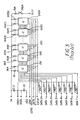
- Fig. 3 illustrates schematically a configuration of the thermal printhead that may be used in accordance with the present invention.
- reference symbols R 1 to R 1536 denote 1536 printing heater elements disposed in the thermal head. Each of these thermal heater elements is formed of a resistor which generates heat when being electrically energized.
- the thermal head heaters R 1 to R 1536 are arranged in a line in a main scan direction perpendicular to the slow scan direction in which the print paper is fed.
- One end of each resistor serving as a thermal head heater element is connected in common to a line for supplying the power supply voltage VH.
- Reference symbol Rph denotes a heater for pre-heating the paper and is optional.
- a switch SWph shown as a mechanical switch but actually is preferably a transistor switch controls the supply of current to the pre-heater.
- the pre-heater Rph and the switch SWph are connected in series between the power supply VH and the power supply VL. Description of the pre-heater may be found in U.S. Patent Application Publication 2001/0033320 published in the name of Sugiyama et al .
- Reference numerals DR1 to DR 24 denote printer drivers (ICs) for driving the thermal head heaters R 1 to R 1536.
- the 24 drivers DR1 to DR 24 are cascaded via data lines so that one line of imprint data can be sent into the drivers R 1 to R 24 by shifting print data DATA0 DATA7 from one driver to the following driver.
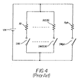
- the drivers DR1 to DR 24 include switches SW1 to SW 1536 (see Fig. 4 ) for controlling the operation of electrically energizing the thermal head heaters R 1 to R 1536. As noted above, although the switches are shown schematically as mechanical switches it is preferred to have the switches be controlled using transistors.
- Terminals through which print data DATA0 through DATA7 are supplied maybe respectively connected to a ground terminal GNDL via pull-down resistors PR0 to PR7.
- the switches SW1 to SW 1536 are disposed in the drivers DR1 to DR 24 such that each driver includes sixty four switches, and each thermal head heater element R1 to R 1536 is connected in series to one corresponding switch, and each series connection of one thermal head heater element and one switch is connected between the positive terminal of the power supply VH and the negative terminal (ground GNDH) thereof.
- some of the thermal head heater elements R 1 to R 1536 are selectively connected to the power supply voltage VH when there is selective turning on of the corresponding switches of switches SW1 to SW 1536.
- Those heating elements selectively connected to the power supply voltage VH generate heat in accordance with and in amounts related to the enablement time they are so connected during a respective line period.
- any of the 1536 thermal head heaters R 1 to R 1536 can be separately turned on by closing the respective one of the 1536 switches SW1 to SW 1536, and record a pixel or spot of color as the respective thermal head heater element generates heat to cause dye to sublimate or diffuse from the respective color patch to the receiver.
- one integrated circuit may contain all the driver circuitry for several thousand switches.
- Fig. 5 illustrates a circuit configuration of the circuit or printer controller 40 for generating various control signals and imprint data signals.
- reference 100 denotes a strobe pulse table which defines a pulse pattern of the strobe signal HLSTR serving as a reference signal according to which the energization of thermal head heaters R 1 to R 1536 are controlled depending upon the printing mode.
- a strobe pulse table outputs a pulse pattern in response to a print mode signal MODE specifying the printing mode in which one of colors of yellow, magenta, cyan and optionally a transparent overcoat (where a quad patch is used).
- the print mode signal MODE also is changed in accordance with the line number being printed as will be discussed further below.
- Reference number 101 denotes a thermal head heater element control signal generator for generating various control signals (enable signal ENBb, load signal LOADb, set signal SETb, high-level strobe signal HLSTR, low-level strobe signal LLSTR, and clock signal DCLK).
- the strobe pulse table 100 in the thermal head heater element control signal generator 101 forms signal generating means for generating a high-level strobe signal HLSTR serving as a reference signal and controlling the operation of energizing the thermal head heater elements depending upon the printing mode selected from a plurality of printing modes in which respective colors are printed.
- Reference number 102 denotes a conversion coefficient table which describes conversion coefficients used in conversion of the gradation of image data PDATA to be printed.
- Reference number 103 denotes an internal gradation converter for converting 8-bit image data PDATA input from a data source with various correction data in the conversion coefficients into a 10-bit internal gradation data. The correction data may correct for non-uniformity of the recording elements which may be part of a predetermined factory calibration in accordance with well-known techniques.
- Reference number 104 denotes a head data buffer for temporarily storing the converted internal gradation data.
- Reference number 105 denotes a head data converter for converting the 10-bit internal gradation data stored in the head data buffer 104 into 8-bit data DATA0 to DATA7 to be sent to the printer drivers. It will be understood that the number of data bits used to print a particular pixel may be more or less than eight bits.
- a microcomputer 90 controls the various motors, generators, converters and tables forming printer controller 40 which may be integrated on the microcomputer or comprises separate integrated circuit components.
- a microcomputer would be programmed to provide the various signals as required in accordance with routine programming skills.
- each printer driver IC (DR1...DR24) and with reference now to Fig. 6 , there may be provided associated with each recording element an exposure counter 200 into which data lines D0-7 are input.
- LOADb Upon establishment of a load signal LOADb, the count value established by the image data signals on lines D0-7 are stored in a first register in the counter.
- the count value in the first register is compared with a count in a second register that counts clock signals input on the line DCLK. As the clock signals are counted, the count in the second register is incremented and when there is an equality of count values in both registers a signal is provided on the line ECO which is one input to an AND gate 210.
- Additional inputs to the AND gate 210 are the strobe signals HLSTR and LLSTR.
- Fig. 7A illustrates an example of the waveforms which are used in control of recording image data.
- the control of transmission of data through the drivers and latching thereof is controlled by the signals DCLK, SETb and LOADb signals as is well known.
- the high-level strobe signal HLSTR is shown to have a duty cycle represented by a delay subsequent to ending of the data transfer period.
- the period represented by the data transfer signal is of sufficient duration to allow data to be serially transferred to all the count registers on the print head so that within each count register there is established a count number representing the time for recording the respective image data by that recording element during that particular line period.
- a delay is established between the start of the high-level strobe signal HLSTR and the end of the data transfer period.
- a duty cycle of 90 percent will be used consistently for print or data lines 1 through 1006 where the mode is that of forming a print of 3 1/2 inches long.
- the 90 percent duty cycle will be used consistently for data lines 1 through 922.
- the duty cycle will gradually decrease preferably linearly.
- Fig. 8 there is an illustration of the high-level strobe signal HLSTR 230 having a 90 percent duty cycle.
- each high-level strobe signal HLSTR there is an illustration of the composition 200 of each high-level strobe signal HLSTR and showing same as being comprised of or in effect forming an envelope for a series of low-level strobe signals LLSTR 240.
- the low-level strobe signals each has a duty cycle of 60 percent which in this embodiment would be consistent for all recording lines wherein only the duty cycle for the high-level strobe signal changes. Examples of values of a period for a low-level strobe pulse is 45 microseconds for a sixty percent duty cycle wherein pulse on time for such LLSTR is 27 microseconds.
- Several hundred low-level strobe pulses may be present within a single high-level strobe signal HLSTR at the 90 percent duty cycle for the high-level strobe signal.
- the duty cycle for the high-level strobe signal HLSTR during recording using the first triad of color patches reduces linearly as illustrated in Fig. 11 and thus the number of low-level strobe signals present within a single high-level strobe signal linearly decreases with the line number since the period and duty cycle for the low-level strobe signal LLSTR is not changed from line to line in this first embodiment.
- the duty cycle for the high-level strobe signal HLSTR is 0 percent for lines 1 through 922.
- the duty cycle for the high-level strobe signal HLSTR increases linearly and thus the number of low-level strobe signals LLSTR present within a single high-level strobe signal HSTR increases linearly with the line number again because the period and duty cycle for the low-level strobe signals LLSTR in this embodiment is not changed from line to line.
- Fig. 7B an example is provided of the signals during recording in the overlap region when recording the second triad of color patches.
- the data input to the exposure counter for this recording element is identical to that input for this line number and color patch when the first triad of color patches was printed.
- the duration of the high-level strobe signal HLSTR is essentially complementary to the duration of the high-level strobe signal used during recording of the same line number and color patch during recording of the first triad of color patches.
- the duty cycle for a particular recording line is 90 - x for the high-level strobe signal during recording using a color patch, for example cyan
- the duty cycle will be x for the high-level strobe signal using the counterpart color patch, cyan, in the second triad of color patches.
- the heater on time will be relatively short due to the ANDing logic operation.
- Fig. 15 there are shown three pixels recorded by the printhead on the receiver sheet using the invention and for printing during the enlarged recording mode wherein two triads of color patches are used.
- the pixel to be formed at each of the three locations is to be formed in the cyan color.
- the pixels to be formed will each be of the same density, say for example 128 of a possible selectable range of 0 through 255. That is, the printhead is capable of printing gray levels dependent upon the data to be recorded in a particular one of the gray levels from 0 through 255.
- Pixel number 300 will be recorded using the cyan color patch of the first triad only, i.e. this pixel is in the region of lines 1 through 922.
- the printhead recording element for recording this pixel will be driven with a predetermined high-level strobe signal HLSTR having a duty cycle of 90 percent. As noted above, within this high-level strobe signal there are a series of low-level strobe signals LLSTR having a duty cycle of sixty percent. The duration of enablement of energy for recording pixel 300 will be dependent upon the density for recording the particular color at that location. The second triad of color patches will not be used at all for recording pixel 300.
- the printhead recording element for recording this pixel will be actuated for recording a portion of this pixel using the cyan color patch of the first triad of color patches and then subsequently used for recording the next portion of this pixel using the cyan color patch of the second triad of color patches.
- the density recorded for each portion of this pixel will be dependent upon the line number. Since the overlap region in this example is defined between lines 923 and 1006, the portion in terms of density of the pixel recorded by the color patch of the first triad will be greater for pixels on line numbers closer to 923 and thus there will be less dye transferred for such pixels from a color patch in the second triad of color patches.
- the portion in terms of density of the pixel recorded by the color patch of the first triad will be less for pixels on line numbers closer to 1006 as there will be more dye transferred for such pixels from a same color of color patch in the second triad of color patches.
- the high-level strobe signal changes from line to line for both the recording using the first triad of color patches and for recording using the second triad of color patches.
- the number of low-level strobe signals for recording the pixel 305 will be about the same as that for recording the pixel 300 except that the recording will be done at two different times using the two different color patches to provide the same density result of 128.
- the overlap region has purposefully been defined as not passing through the center of the print. Since this region may not be as well recorded as that using a single triad of color patches it is preferable to avoid placing same in the middle of the print. In this example the overlap region is approximately slightly more than one-quarter of an inch long in the direction of the advancement of the receiver sheet.
- the high-level strobe signal HLSTR remains constant at 90 percent duty cycle and is similar to that used in the non-overlap area.
- the low-level strobe signal LLSTR is modified on a line by line basis linearly so that in the non-overlap area the duty cycle for the low-level strobe signal LLSTR is sixty percent duty cycle, see Fig. 12 .
- This low-level strobe signal duty cycle decreases to zero at line 1006 during recording of the image using the first triad of color patches. Illustrated in Fig. 14 is the low-level strobe signal of the duty cycle of 30 percent whereas in Fig.
- the low-level strobe signal has a duty cycle of sixty percent which is the case in the non-overlap area.
- the low-level strobe signal LLSTR starts out at zero percent duty cycle for line 923 and linearly increases from zero percent to sixty percent duty cycle at line 1006. It will be understood that the number of low-level strobe signals in a high-level strobe signal of a predetermined remains the same for the embodiment of Figs. 12-14 since the duration of the on time of the heater element is related to the duty cycle of the low-level strobe signal multiplied by the number of such signals.
- the internal gradation converter 103 is provided with a predetermined setting when printing using the first set of color patches and printing lines 1 through 922. Such setting can be accomplished by adjustment of conversion coefficients from table 102 or from the input of various correction data input into the converter 103.
- the settings for such internal gradation converter 103 will be the same as for recording using the first triad of color patches, wherein the only difference is that the image data PDATA is likely to vary in accordance with the image.
- lines 923 through 1006 a different lookup table of values is provided to modify the image data in accordance with line number of the line being recorded.
- the density of the image data will be changed with line numbers so that for gray level pixels recorded using the first triad of color patches, and such pixels being located closer to line 923, the amount of contribution by the first set of color patches to record that pixel will be greater and the contribution by the second set of color patches will be less.
- the density of the images is adjusted for use of values from a lookup table so that the contribution to density of the resulting printed pixel is greater for the second triad of color patches for pixels that are closer to line 1006.
- the transparent overcoat may be applied or recorded over the image using a different approach.
- the second transparent patch and forming a part of the second quad set of color patches is then used to be applied over lines 923 through 2101.
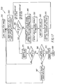
- step 375 A determination is made in step 380 as to whether or not the three or four color (three colors and one transparency) patches are completed, step 380. If not printing is begun with the next color patch, step 320.
- Steps 330,340,350,360,370 are repeated until the terminal count N is reached for that color patch.
- step 380 a determination is made as to whether or not the yellow, magenta, cyan and optionally the transparent patch are completed for that triad or quad of color patches. If yes then a determination is made in step 385 as to whether or not printing with the second color patch set has been completed. If not, advancement is made of the second color patch set for printing, step 387.
- the print is removed from the printer, step 390 and printing stops for that print.
- the printing of the two sub- images to form a composite image has the pixels in the overlap region formed by combining deposition of material from the color patches of each triad or quad of color patches. That is a gray level pixel in the overlap region is formed by material from both triads or both quads.
- the high-level strobe signal HLSTR and/or the low-level strobe signal LLSTR are modified on a changing line by line basis as described herein to adjust the contributions of the transference of colorants from each of the triads or quads to each gray level pixel.
- a gray level pixel is defined to have a density that can be made variable in accordance with image data to more than two levels of density including no density.
- the receiver sheet employed herein may be a discrete sheet of predetermined size or a continuous receiver sheet in which the composite image formed by the two sub- images are formed.
- the receiver sheet may have microperfs to define an image area so that the composite image is formed within the boundary defined by the microperfs and optionally the side edges of the receiver sheet. The microperfs may then be used to facilitate removal of the unprinted border of the receiver sheet from the printed portion having the composite image.
Landscapes
- Electronic Switches (AREA)
Applications Claiming Priority (2)
| Application Number | Priority Date | Filing Date | Title |
|---|---|---|---|
| US10/702,896 US6961075B2 (en) | 2003-11-06 | 2003-11-06 | Method and apparatus for thermal printing of longer length images by the use of multiple dye color patch triads or quads |
| PCT/US2004/034702 WO2005047004A2 (en) | 2003-11-06 | 2004-10-21 | Thermal printing of longer length images |
Publications (2)
| Publication Number | Publication Date |
|---|---|
| EP1682353A2 EP1682353A2 (en) | 2006-07-26 |
| EP1682353B1 true EP1682353B1 (en) | 2008-05-14 |
Family
ID=34551764
Family Applications (1)
| Application Number | Title | Priority Date | Filing Date |
|---|---|---|---|
| EP04795812A Expired - Lifetime EP1682353B1 (en) | 2003-11-06 | 2004-10-21 | Thermal printing of longer length images |
Country Status (5)
| Country | Link |
|---|---|
| US (1) | US6961075B2 (https=) |
| EP (1) | EP1682353B1 (https=) |
| JP (1) | JP2007510562A (https=) |
| DE (1) | DE602004013821D1 (https=) |
| WO (1) | WO2005047004A2 (https=) |
Families Citing this family (19)
| Publication number | Priority date | Publication date | Assignee | Title |
|---|---|---|---|---|
| JP2004074459A (ja) * | 2002-08-12 | 2004-03-11 | Pentax Corp | 多色発色用サーマルプリンタ、多色発色方法及び多色発色システム |
| JP5134822B2 (ja) * | 2006-01-31 | 2013-01-30 | 株式会社東芝 | 画像形成方法、画像形成装置および印刷物 |
| JP4752535B2 (ja) * | 2006-02-15 | 2011-08-17 | 富士ゼロックス株式会社 | 画像処理装置、画像処理方法、及び画像処理プログラム |
| US20080012928A1 (en) * | 2006-07-13 | 2008-01-17 | Eastman Kodak Company | Producing standard format and wide-format prints with efficient donor material use |
| US8244058B1 (en) | 2008-05-30 | 2012-08-14 | Adobe Systems Incorporated | Method and apparatus for managing artifacts in frequency domain processing of light-field images |
| US8315476B1 (en) * | 2009-01-20 | 2012-11-20 | Adobe Systems Incorporated | Super-resolution with the focused plenoptic camera |
| US8189089B1 (en) | 2009-01-20 | 2012-05-29 | Adobe Systems Incorporated | Methods and apparatus for reducing plenoptic camera artifacts |
| US8228417B1 (en) | 2009-07-15 | 2012-07-24 | Adobe Systems Incorporated | Focused plenoptic camera employing different apertures or filtering at different microlenses |
| US8817015B2 (en) | 2010-03-03 | 2014-08-26 | Adobe Systems Incorporated | Methods, apparatus, and computer-readable storage media for depth-based rendering of focused plenoptic camera data |
| US8749694B2 (en) | 2010-08-27 | 2014-06-10 | Adobe Systems Incorporated | Methods and apparatus for rendering focused plenoptic camera data using super-resolved demosaicing |
| US8665341B2 (en) | 2010-08-27 | 2014-03-04 | Adobe Systems Incorporated | Methods and apparatus for rendering output images with simulated artistic effects from focused plenoptic camera data |
| US8724000B2 (en) | 2010-08-27 | 2014-05-13 | Adobe Systems Incorporated | Methods and apparatus for super-resolution in integral photography |
| US8803918B2 (en) | 2010-08-27 | 2014-08-12 | Adobe Systems Incorporated | Methods and apparatus for calibrating focused plenoptic camera data |
| US9197798B2 (en) | 2011-03-25 | 2015-11-24 | Adobe Systems Incorporated | Thin plenoptic cameras using microspheres |
| US8477162B1 (en) | 2011-10-28 | 2013-07-02 | Graphic Products, Inc. | Thermal printer with static electricity discharger |
| US8482586B1 (en) | 2011-12-19 | 2013-07-09 | Graphic Products, Inc. | Thermal printer operable to selectively print sub-blocks of print data and method |
| US8553055B1 (en) | 2011-10-28 | 2013-10-08 | Graphic Products, Inc. | Thermal printer operable to selectively control the delivery of energy to a print head of the printer and method |
| JP6463088B2 (ja) * | 2014-11-17 | 2019-01-30 | キヤノン株式会社 | 印刷装置、印刷装置の制御方法 |
| JP6509056B2 (ja) * | 2015-06-29 | 2019-05-08 | 三菱電機株式会社 | 熱転写型プリンタおよびその印刷制御方法 |
Family Cites Families (10)
| Publication number | Priority date | Publication date | Assignee | Title |
|---|---|---|---|---|
| US4745413A (en) * | 1987-06-03 | 1988-05-17 | Eastman Kodak Company | Energizing heating elements of a thermal printer |
| WO1991017054A1 (fr) * | 1990-05-07 | 1991-11-14 | Dai Nippon Printing Co., Ltd. | Procede, dispositif et substance de formation d'images |
| US5132701A (en) * | 1991-06-19 | 1992-07-21 | Eastman Kodak Company | Method and apparatus for printing an image in multiple sub-images |
| US5140341A (en) * | 1991-06-17 | 1992-08-18 | Eastman Kodak Company | Method and apparatus for thermally printing large images with small dye-donor patches |
| EP0522980A3 (en) | 1991-06-17 | 1993-04-14 | Eastman Kodak Company | Method and apparatus for thermally printing large images with small dye-donor patches |
| US5450099A (en) * | 1993-04-08 | 1995-09-12 | Eastman Kodak Company | Thermal line printer with staggered head segments and overlap compensation |
| WO1996023662A1 (en) | 1995-01-31 | 1996-08-08 | Summagraphics Corporation | Non-linear edge stitching apparatus and method |
| JP3905177B2 (ja) * | 1997-05-15 | 2007-04-18 | 富士フイルム株式会社 | 色変換調整方法 |
| US6106172A (en) | 1998-02-24 | 2000-08-22 | Eastman Kodak Company | Method and printer utilizing a single microprocessor to modulate a printhead and implement printing functions |
| JP2000255108A (ja) * | 1999-03-08 | 2000-09-19 | Fuji Photo Film Co Ltd | プリンタのキャリブレーション方法及び装置並びにプリンタ |
-
2003
- 2003-11-06 US US10/702,896 patent/US6961075B2/en not_active Expired - Lifetime
-
2004
- 2004-10-21 WO PCT/US2004/034702 patent/WO2005047004A2/en not_active Ceased
- 2004-10-21 DE DE602004013821T patent/DE602004013821D1/de not_active Expired - Lifetime
- 2004-10-21 EP EP04795812A patent/EP1682353B1/en not_active Expired - Lifetime
- 2004-10-21 JP JP2006539528A patent/JP2007510562A/ja active Pending
Also Published As
| Publication number | Publication date |
|---|---|
| JP2007510562A (ja) | 2007-04-26 |
| US20050099487A1 (en) | 2005-05-12 |
| WO2005047004A3 (en) | 2005-11-17 |
| US6961075B2 (en) | 2005-11-01 |
| WO2005047004A2 (en) | 2005-05-26 |
| EP1682353A2 (en) | 2006-07-26 |
| DE602004013821D1 (de) | 2008-06-26 |
Similar Documents
| Publication | Publication Date | Title |
|---|---|---|
| EP1682353B1 (en) | Thermal printing of longer length images | |
| EP0095380A2 (en) | Thermal transfer printing method | |
| US5075698A (en) | Method of driving a recording head and a recording apparatus utilizing this method | |
| US6120198A (en) | Printing head drive apparatus and method for driving printing head | |
| EP1671801A2 (en) | Method and apparatus for forming an image | |
| US6344867B2 (en) | Thermal printing method and thermal printer capable of efficient transfer of data | |
| JPS61256862A (ja) | サ−マルヘツドを用いたカラ−印刷方法 | |
| JP3621777B2 (ja) | カラー記録装置及び記録方法 | |
| JP3068729B2 (ja) | 画像記録方法 | |
| JP3483341B2 (ja) | カラー記録装置及び記録方法 | |
| JPH05278253A (ja) | サーマルヘッドの駆動方法 | |
| JP3916709B2 (ja) | カラー画像記録方法、カラー画像記録装置、及びカラー画像記録制御方法 | |
| US6288735B1 (en) | Color image recording method, color image recording apparatus, and color image recording controlling method | |
| JPH08197769A (ja) | サーマルプリンタ | |
| JPH0872284A (ja) | 熱転写カラー記録装置 | |
| JP2002178552A (ja) | マルチサーマルヘッド駆動方法およびマルチサーマルヘッドプリンタ | |
| JP3230918B2 (ja) | カラー熱転写プリンタにおける階調制御方法 | |
| JP3727152B2 (ja) | サーマルヘッドの駆動方法 | |
| JPH10151781A (ja) | カラー画像記録方法、カラー画像記録装置、及びカラー画像記録制御方法 | |
| JP2817734B2 (ja) | 多色感熱プリント装置 | |
| JPH10217528A (ja) | カラー画像記録方法、カラー画像記録装置、及びカラー画像記録制御方法 | |
| JPH08281995A (ja) | インクシート、熱転写記録装置及び中間調記録方法 | |
| JPH0542706A (ja) | 多階調熱記録方法 | |
| JPH1142805A (ja) | サーマルプリント方法及びプリンタ | |
| US20040070635A1 (en) | Method and apparatus for reducing uneven use of heating elements on thermal print head |
Legal Events
| Date | Code | Title | Description |
|---|---|---|---|
| PUAI | Public reference made under article 153(3) epc to a published international application that has entered the european phase |
Free format text: ORIGINAL CODE: 0009012 |
|
| 17P | Request for examination filed |
Effective date: 20060410 |
|
| AK | Designated contracting states |
Kind code of ref document: A2 Designated state(s): DE FR GB |
|
| DAX | Request for extension of the european patent (deleted) | ||
| RBV | Designated contracting states (corrected) |
Designated state(s): DE FR GB |
|
| GRAP | Despatch of communication of intention to grant a patent |
Free format text: ORIGINAL CODE: EPIDOSNIGR1 |
|
| GRAS | Grant fee paid |
Free format text: ORIGINAL CODE: EPIDOSNIGR3 |
|
| GRAA | (expected) grant |
Free format text: ORIGINAL CODE: 0009210 |
|
| AK | Designated contracting states |
Kind code of ref document: B1 Designated state(s): DE FR GB |
|
| REG | Reference to a national code |
Ref country code: GB Ref legal event code: FG4D |
|
| REF | Corresponds to: |
Ref document number: 602004013821 Country of ref document: DE Date of ref document: 20080626 Kind code of ref document: P |
|
| PLBE | No opposition filed within time limit |
Free format text: ORIGINAL CODE: 0009261 |
|
| STAA | Information on the status of an ep patent application or granted ep patent |
Free format text: STATUS: NO OPPOSITION FILED WITHIN TIME LIMIT |
|
| 26N | No opposition filed |
Effective date: 20090217 |
|
| REG | Reference to a national code |
Ref country code: DE Ref legal event code: R082 Ref document number: 602004013821 Country of ref document: DE Representative=s name: WAGNER & GEYER PARTNERSCHAFT PATENT- UND RECHT, DE |
|
| REG | Reference to a national code |
Ref country code: DE Ref legal event code: R082 Ref document number: 602004013821 Country of ref document: DE Representative=s name: WAGNER & GEYER PARTNERSCHAFT MBB PATENT- UND R, DE Effective date: 20141028 Ref country code: DE Ref legal event code: R082 Ref document number: 602004013821 Country of ref document: DE Representative=s name: WAGNER & GEYER PARTNERSCHAFT PATENT- UND RECHT, DE Effective date: 20141028 Ref country code: DE Ref legal event code: R081 Ref document number: 602004013821 Country of ref document: DE Owner name: KODAK ALARIS INC., ROCHESTER, US Free format text: FORMER OWNER: EASTMAN KODAK CO., ROCHESTER, N.Y., US Effective date: 20141028 |
|
| REG | Reference to a national code |
Ref country code: FR Ref legal event code: CD Owner name: KODAK ALARIS INC., US Effective date: 20141212 Ref country code: FR Ref legal event code: TP Owner name: KODAK ALARIS INC., US Effective date: 20141212 |
|
| REG | Reference to a national code |
Ref country code: GB Ref legal event code: 732E Free format text: REGISTERED BETWEEN 20150108 AND 20150114 |
|
| REG | Reference to a national code |
Ref country code: FR Ref legal event code: PLFP Year of fee payment: 13 |
|
| REG | Reference to a national code |
Ref country code: FR Ref legal event code: PLFP Year of fee payment: 14 |
|
| REG | Reference to a national code |
Ref country code: FR Ref legal event code: PLFP Year of fee payment: 15 |
|
| PGFP | Annual fee paid to national office [announced via postgrant information from national office to epo] |
Ref country code: GB Payment date: 20230914 Year of fee payment: 20 |
|
| PGFP | Annual fee paid to national office [announced via postgrant information from national office to epo] |
Ref country code: FR Payment date: 20230914 Year of fee payment: 20 |
|
| PGFP | Annual fee paid to national office [announced via postgrant information from national office to epo] |
Ref country code: DE Payment date: 20230915 Year of fee payment: 20 |
|
| REG | Reference to a national code |
Ref country code: DE Ref legal event code: R071 Ref document number: 602004013821 Country of ref document: DE |
|
| REG | Reference to a national code |
Ref country code: GB Ref legal event code: PE20 Expiry date: 20241020 |
|
| PG25 | Lapsed in a contracting state [announced via postgrant information from national office to epo] |
Ref country code: GB Free format text: LAPSE BECAUSE OF EXPIRATION OF PROTECTION Effective date: 20241020 |
|
| PG25 | Lapsed in a contracting state [announced via postgrant information from national office to epo] |
Ref country code: GB Free format text: LAPSE BECAUSE OF EXPIRATION OF PROTECTION Effective date: 20241020 |