EP1680065B1 - Dispositif indicateur a indicateur de dosage d'alarme - Google Patents
Dispositif indicateur a indicateur de dosage d'alarme Download PDFInfo
- Publication number
- EP1680065B1 EP1680065B1 EP04789791.3A EP04789791A EP1680065B1 EP 1680065 B1 EP1680065 B1 EP 1680065B1 EP 04789791 A EP04789791 A EP 04789791A EP 1680065 B1 EP1680065 B1 EP 1680065B1
- Authority
- EP
- European Patent Office
- Prior art keywords
- indicator
- container
- indicating device
- members
- primary
- Prior art date
- Legal status (The legal status is an assumption and is not a legal conclusion. Google has not performed a legal analysis and makes no representation as to the accuracy of the status listed.)
- Active
Links
- 239000000126 substance Substances 0.000 claims description 34
- 230000004044 response Effects 0.000 claims description 5
- 239000003814 drug Substances 0.000 description 31
- 230000000875 corresponding effect Effects 0.000 description 25
- 210000003811 finger Anatomy 0.000 description 18
- 238000007373 indentation Methods 0.000 description 14
- 230000007246 mechanism Effects 0.000 description 13
- 239000000443 aerosol Substances 0.000 description 10
- 239000000853 adhesive Substances 0.000 description 8
- 230000001070 adhesive effect Effects 0.000 description 8
- 230000006870 function Effects 0.000 description 8
- 230000009467 reduction Effects 0.000 description 8
- 239000000463 material Substances 0.000 description 6
- 239000004033 plastic Substances 0.000 description 6
- 229920003023 plastic Polymers 0.000 description 6
- 238000000034 method Methods 0.000 description 5
- 230000007704 transition Effects 0.000 description 5
- 230000001419 dependent effect Effects 0.000 description 4
- 230000000994 depressogenic effect Effects 0.000 description 4
- 238000004519 manufacturing process Methods 0.000 description 4
- 238000005452 bending Methods 0.000 description 3
- 230000008901 benefit Effects 0.000 description 3
- 239000003086 colorant Substances 0.000 description 3
- 238000003780 insertion Methods 0.000 description 3
- 230000037431 insertion Effects 0.000 description 3
- 238000009434 installation Methods 0.000 description 3
- 230000013011 mating Effects 0.000 description 3
- 239000002184 metal Substances 0.000 description 3
- 230000008569 process Effects 0.000 description 3
- 210000003813 thumb Anatomy 0.000 description 3
- 230000000007 visual effect Effects 0.000 description 3
- XECAHXYUAAWDEL-UHFFFAOYSA-N acrylonitrile butadiene styrene Chemical compound C=CC=C.C=CC#N.C=CC1=CC=CC=C1 XECAHXYUAAWDEL-UHFFFAOYSA-N 0.000 description 2
- 229920000122 acrylonitrile butadiene styrene Polymers 0.000 description 2
- 239000004676 acrylonitrile butadiene styrene Substances 0.000 description 2
- 239000004479 aerosol dispenser Substances 0.000 description 2
- 230000008859 change Effects 0.000 description 2
- 230000006835 compression Effects 0.000 description 2
- 238000007906 compression Methods 0.000 description 2
- 230000000881 depressing effect Effects 0.000 description 2
- 230000000694 effects Effects 0.000 description 2
- 238000005530 etching Methods 0.000 description 2
- 238000000465 moulding Methods 0.000 description 2
- 238000007649 pad printing Methods 0.000 description 2
- 238000007639 printing Methods 0.000 description 2
- 238000003466 welding Methods 0.000 description 2
- DHKHKXVYLBGOIT-UHFFFAOYSA-N acetaldehyde Diethyl Acetal Natural products CCOC(C)OCC DHKHKXVYLBGOIT-UHFFFAOYSA-N 0.000 description 1
- 125000002777 acetyl group Chemical class [H]C([H])([H])C(*)=O 0.000 description 1
- 230000009471 action Effects 0.000 description 1
- 230000002411 adverse Effects 0.000 description 1
- 230000000712 assembly Effects 0.000 description 1
- 238000000429 assembly Methods 0.000 description 1
- 239000007767 bonding agent Substances 0.000 description 1
- 230000002596 correlated effect Effects 0.000 description 1
- 229940079593 drug Drugs 0.000 description 1
- 230000008030 elimination Effects 0.000 description 1
- 238000003379 elimination reaction Methods 0.000 description 1
- 239000006260 foam Substances 0.000 description 1
- 230000006872 improvement Effects 0.000 description 1
- 238000010348 incorporation Methods 0.000 description 1
- 230000003993 interaction Effects 0.000 description 1
- 238000005304 joining Methods 0.000 description 1
- 239000007788 liquid Substances 0.000 description 1
- 229940071648 metered dose inhaler Drugs 0.000 description 1
- 230000004048 modification Effects 0.000 description 1
- 238000012986 modification Methods 0.000 description 1
- 239000003973 paint Substances 0.000 description 1
- 230000002093 peripheral effect Effects 0.000 description 1
- 239000004417 polycarbonate Substances 0.000 description 1
- 229920000515 polycarbonate Polymers 0.000 description 1
- 238000002360 preparation method Methods 0.000 description 1
- 230000000750 progressive effect Effects 0.000 description 1
- 230000003252 repetitive effect Effects 0.000 description 1
- 230000011218 segmentation Effects 0.000 description 1
- 230000008719 thickening Effects 0.000 description 1
- 239000011800 void material Substances 0.000 description 1
Images


Classifications
-
- A—HUMAN NECESSITIES
- A61—MEDICAL OR VETERINARY SCIENCE; HYGIENE
- A61M—DEVICES FOR INTRODUCING MEDIA INTO, OR ONTO, THE BODY; DEVICES FOR TRANSDUCING BODY MEDIA OR FOR TAKING MEDIA FROM THE BODY; DEVICES FOR PRODUCING OR ENDING SLEEP OR STUPOR
- A61M15/00—Inhalators
- A61M15/0065—Inhalators with dosage or measuring devices
- A61M15/0068—Indicating or counting the number of dispensed doses or of remaining doses
- A61M15/007—Mechanical counters
- A61M15/0071—Mechanical counters having a display or indicator
- A61M15/0076—Mechanical counters having a display or indicator on a drum
-
- A—HUMAN NECESSITIES
- A61—MEDICAL OR VETERINARY SCIENCE; HYGIENE
- A61M—DEVICES FOR INTRODUCING MEDIA INTO, OR ONTO, THE BODY; DEVICES FOR TRANSDUCING BODY MEDIA OR FOR TAKING MEDIA FROM THE BODY; DEVICES FOR PRODUCING OR ENDING SLEEP OR STUPOR
- A61M15/00—Inhalators
- A61M15/0065—Inhalators with dosage or measuring devices
- A61M15/0068—Indicating or counting the number of dispensed doses or of remaining doses
- A61M15/007—Mechanical counters
- A61M15/0071—Mechanical counters having a display or indicator
- A61M15/0073—Mechanical counters having a display or indicator on a ring
-
- A—HUMAN NECESSITIES
- A61—MEDICAL OR VETERINARY SCIENCE; HYGIENE
- A61M—DEVICES FOR INTRODUCING MEDIA INTO, OR ONTO, THE BODY; DEVICES FOR TRANSDUCING BODY MEDIA OR FOR TAKING MEDIA FROM THE BODY; DEVICES FOR PRODUCING OR ENDING SLEEP OR STUPOR
- A61M15/00—Inhalators
- A61M15/0065—Inhalators with dosage or measuring devices
- A61M15/0068—Indicating or counting the number of dispensed doses or of remaining doses
- A61M15/007—Mechanical counters
- A61M15/0071—Mechanical counters having a display or indicator
- A61M15/0075—Mechanical counters having a display or indicator on a disc
-
- A—HUMAN NECESSITIES
- A61—MEDICAL OR VETERINARY SCIENCE; HYGIENE
- A61M—DEVICES FOR INTRODUCING MEDIA INTO, OR ONTO, THE BODY; DEVICES FOR TRANSDUCING BODY MEDIA OR FOR TAKING MEDIA FROM THE BODY; DEVICES FOR PRODUCING OR ENDING SLEEP OR STUPOR
- A61M15/00—Inhalators
- A61M15/009—Inhalators using medicine packages with incorporated spraying means, e.g. aerosol cans
-
- A—HUMAN NECESSITIES
- A61—MEDICAL OR VETERINARY SCIENCE; HYGIENE
- A61M—DEVICES FOR INTRODUCING MEDIA INTO, OR ONTO, THE BODY; DEVICES FOR TRANSDUCING BODY MEDIA OR FOR TAKING MEDIA FROM THE BODY; DEVICES FOR PRODUCING OR ENDING SLEEP OR STUPOR
- A61M2205/00—General characteristics of the apparatus
- A61M2205/60—General characteristics of the apparatus with identification means
- A61M2205/6045—General characteristics of the apparatus with identification means having complementary physical shapes for indexing or registration purposes
Definitions
- the present invention relates generally to an indicating device for indicating the number of dosages that have been dispensed from or remain in a container, and in particular, to an indicating device having at least a first and second indicator member with primary and secondary dosage indicia respectively.
- Aerosol dispensing devices have been developed that include a dose indicating device to indicate the number of metered doses that have been dispensed from the device, or to indicate the number of doses remaining therein.
- a dose indicating device to indicate the number of metered doses that have been dispensed from the device, or to indicate the number of doses remaining therein.
- patients have certain conditions that can be treated with medicaments dispensed in an aerosol and administered to the patient by inhalation.
- the aerosol with medicaments are contained in a container, and dispensed in metered, or measured, dosages with an inhalation device, or actuator boot.
- the inhalation device it can be important for the patient to be able to ascertain the number of metered doses remaining in the container, either by an indication of the number remaining therein or by knowledge of the number already dispensed therefrom, such that the patient is not caught unaware with an empty container when in need of the medicament.
- the inhalation device it may be important for the inhalation device to provide an accurate indication of either the number of doses remaining in the container, or the number of doses already dispensed therefrom.
- a conventional aerosol container typically includes a body and a valve stem that can be depressed relative to the body so as to emit the metered dose of aerosol and medicament.
- the container typically is supplied with a predetermined number of metered doses, generally on the order of about 200, such that the counting of the number of valve stem depressions, and corresponding number of dispensed metered doses, can be directly correlated with the number of doses remaining in the container.
- the container In operation, the container is typically received within a housing of the inhalation device, wherein the valve is brought into engagement with a support block in the housing.
- the user administers the medicament by moving the container relative to the housing so as to depress the valve stem and internal valve and thereby release a metered dose, which is typically administered to the user through a port or mouthpiece extending from the housing.
- the valve stem which is typically spring loaded, biases the container away from the support block so as to again move the container relative to the housing. In this way, a metered dose of medicament is administered by each cycle of linear reciprocal movement of the container relative to the housing.
- Some actuator boots, or other devices attached to the medicament container have indicating devices that convert the linear reciprocal movement of the container relative to the housing into a one-way, or single-cycle, movement of an indicator, wherein the indicator identifies the relative fullness of the container, the number of metered doses remaining therein or the number of doses already administered.
- these actuator boots with indicators, or separate indicator devices have provided the advantage of generally being able to keep track of the number of dosages, there remains room for improvement.
- many known indicating devices provide only a numerical indication of the number of doses of substance that have been dispensed from or remain in the container.
- the user can become desensitized to the indicating device and may become caught unaware that the medicament in the container has been dissipated notwithstanding that the indicating device is working properly and provides an accurate accounting of the number of doses of medicament dispensed from or remaining in the container.
- Prior art document US 2002/153005 A1 relates to an indicating device suitable for indicating the number of metered dosages that have been dispensed from or remain in a container including a base member adapted to be mounted to the container and a cap member moveably connected to the base member.
- the cap member is moveable relative to the base member along an axial path between a first position and a second position a predetermined number of axial movements.
- An indicator member is rotatably mounted to the cap member.
- a first lock member disposed on the base member, and a second lock member is disposed on one of the indicator member and the cap member.
- the first and second lock members are engaged after the predetermined number of axial movements of the cap member relative to the base member, wherein the first and second lock members maintain the cap member and the base member in one of the first position and the second position when engaged.
- a preferred embodiment of a method for indicating the number of metered dosages of medicaments dispensed from or remaining in a container is provided.
- an indicating device is provided as defined in claim 1.
- an indicating device suitable for indicating the number of dosages of a substance that have been dispensed from or remain in a container includes at least one first indicator member moveable to a plurality of positions and a second indicator member moveable in response to a predetermined number of movements of the at least one first indicator member.
- the at least one first indicator member includes primary dosage indicia adapted to indicate the number of dosages of substance that have been dispensed from or remain in the container.
- the second indicator member includes secondary dosage indicia adapted to indicate that less than a minimum predetermined number of dosages of substance remain in the container.
- the primary dosage indicia are configured as numerical indicia and the secondary dosage indicia are configured as color indicia.
- the at least one first indicator member includes a plurality of coaxially mounted primary indicator members rotatable about a first axis of rotation.
- the second indicating member is rotatably mounted about a second axis of rotation, or is translatably moveable within a plane.
- the second indicator member serves as an auxiliary indicator that provides the user with a warning that the container has less than a minimum predetermined number of dosages of substance remaining therein.
- the secondary indicia can include color indicia that changes once a predetermined number of actuations has occurred.
- user is provided with new indicia or stimulus that draws the user's attention and alerts the user that the container may be running low in the event that the user has become desensitized to the primary dosage indicia.
- the user is provided with advance warning that the container is running low, so as to thereby minimize the chance that they may be caught unaware with an empty container when in need of the substance, such as a medicament.
- the auxiliary indicator can be incorporated with a minimal number of additional parts and is relatively robust in operation.
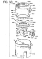
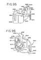
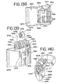
- an aerosol dispenser is shown as including a housing 200, or actuator boot, and a container 12 disposed therein.
- the housing has a longitudinally extending cavity 202 shaped to receive the container.
- a top portion of the housing is generally open such that the container can be inserted in the housing through an opening 204 and be installed therein with a bottom end 14 of the container protruding from the housing so as to be exposed to the user for actuation.
- the terms “longitudinal” and “axial” as used herein are intended to indicate the direction of the reciprocal movement of the container relative to the housing, and of an indicating device cap member relative to a base member.
- the terms “top,” “bottom,” “upwardly” and “downwardly” are intended to indicate directions when viewing the inhalation devices as shown in the Figures, but with the understanding that the container is inverted such that the top surface thereof is located adjacent the bottom of the housing and vice versa.
- a user can use the container and dispenser in any number of positions, including but not limited to the preferred upright position shown in FIGS. 31 and 32 .
- the terms “connect,” “connected,” “couple,” and “coupled,” and equivalents thereof, refers to the connection of two components directly, or indirectly, i.e., by way of one or more intervening components.
- a cylindrical support block 212 having a well 214 is formed in a bottom portion 206 of the housing.
- An orifice 210 penetrates the support block to communicate with a bottom portion of the well.
- a mouthpiece 208 intended for insertion into the mouth of a patient, forms an exhaust port 216 that communicates with the orifice and well.
- the mouthpiece 208 extends laterally from the housing so as to facilitate insertion of the mouthpiece into the mouth of the patient.
- the container 12 is cylindrical and has a hub 16 disposed on a top surface 17 thereof.
- a valve stem 18 extends longitudinally from the hub.
- the valve stem extends coaxially from the container and is biased outwardly therefrom by a spring (not shown) mounted within the valve stem of the container.
- the container 12 is mounted in the housing by press fitting the valve stem 18 in the well 214 of the support block.
- the container 12 is filled with a substance which is dispensed therefrom in specific metered doses by an actuation thereof effected by depressing or moving the valve stem 18 from an extended closed position to a depressed open position.
- the substance is a medicament, although it should be understood that the container may be used to hold a variety of non-medicinal substances, including, but not limited to, various liquids, foams or aerosols.
- the container is a pressurized, metered dose inhaler. A single metered dose is dispensed from the container by each reciprocal, longitudinal movement of the valve stem, or actuation of the container.
- valve system can be actuated by a variety of actuators, including, but not limited to, various pumps, levers, actuator boots, buttons and the like.
- the container and valve system is breath-actuated, meaning they are actuated in response to the user inhaling, for example by inhaling through the mouthpiece.
- the valve system can be actuated by an actuator moveable relative to the container and housing such that the container remains stationary relative to the housing.
- the opening of the valve stem is effected by moving the container 12 reciprocally within the housing 200 along a longitudinal axis, defined by the valve stem and the reciprocal movement of the container, by depressing the bottom end 14 of the container relative to the housing so as to move the valve stem 18 to the open position as it is supported within the well by the support block.
- the container dispenses a metered dose of a substance through the well 214 and orifice 210.
- the substance for example an aerosol and medicament, are then transmitted to the patient through the exhaust port 216 of the mouthpiece by way of either a self-generated or assisted airflow.
- the housing and holder for the container are attached to a component having a chamber with an output end.
- Examples of these kinds of delivery systems are shown for example in U.S. Patent 5,012,803, issued May 7, 1991 , and U.S. Patent 4,460,412, issued September 11, 1984 . (No license, expressed or implied, is intended to be granted to any patent by reason of the incorporation by reference herein).
- the component having the chamber can be adapted to receive the mouthpiece of the housing, or it can be integrally connected with a holder supporting the container.
- the metered dose of medicament in aerosol is first dispensed from the container into the chamber, and thereafter inhaled by the patient.
- the container 12 is intended to dispense a predetermined number of metered doses of a substance, such as a medicament, upon a corresponding number of predetermined actuations of the container.
- a substance such as a medicament
- conventional inhaler containers typically hold on the order of 100 to 200 metered doses. It should be understood, however, that the range of available doses could potentially vary from as few as one dose to as many as 500, or even more, depending, for example, on the capacity of the container, and/or the size of the metering dose valve. In operation, it can be important for the patient to be aware of the number of metered doses remaining in the container such that the patient is not caught unaware with an empty container when in need of the medicament.
- the primary indicating device 10 indicates the number of metered doses that have been dispensed from or remain in the container.
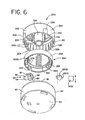
- the primary indicating device 10, 200, 500 includes an indicating device housing comprised of a cap member 20, 220, 520 disposed in a base member 40, 540.
- the base member 40 is configured such that it can be mounted to the bottom of the container 12.
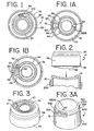
- FIGS. 1-10 a first embodiment, shown in FIGS.
- the base member includes a convex, or curved bottom portion 50, or floor, which is shaped to be received in and to mate with the bottom end 14 of the container, which has a concave or inwardly curved contour (see FIG. 2 ).
- the base member 40 is preferably connected to the bottom of the container, for example and without limitation by bonding with adhesive, double sided tape, or similar bonding agent.
- a label, or other wrapper is wrapped around the side of the base and the container to join the base to the container.
- the outer circumferential surface of the base is substantially the same as outer circumferential surface of the container, which facilitates the joining thereof by way of a wrapper.
- a circumferential skirt member 94 extends upwardly from the base portion to form a cavity 96.
- the base member 140 includes a bottom portion 150, a downwardly depending circumferential skirt 152 and an upwardly depending circumferential skirt 156.
- Depending skirt 152 forms a recess or cavity 154 which is shaped to receive the bottom end of the container.
- the base member is fixedly mounted on the container by connecting one or more of the bottom portion or skirt to the container, for example and without limitation by bonding or by press fitting the container in the cavity 154 so as to provide an interference fit between the container and the depending skirt.
- the upwardly depending skirt 156 and bottom portion form an upper cavity 158 overlying the lower cavity 154.
- an adapter member 90 is connected to one of the above-mentioned base members, for example and without limitation by way of bonding, an interference fit, a snap fit, or a threadable engagement.
- the adapter member 90 preferably has a cylindrical configuration and comprises a circumferential skirt 92 that is shaped to receive the bottom end of the container.
- the adapter can be connected to the container, for example by way of bonding, an interference fit, or both.
- Adapters having different internal diameters can be provided such that a single indicating device having a modular base member can be mounted on various aerosol containers having a variety of outer diameters.
- the base member 1040 includes a downwardly depending circumferential skirt 1152 forming a recess 1154.
- the skirt 1152 includes one or more steps 1155 or shoulders, which form various inner diameters in the base member 1040.
- a single base member 1040 can be used with containers having different diameters.
- the base member could be configured with additional steps so as to provide a plurality of various inner diameters dimensioned to receive various containers by way of a friction fit.
- the skirt 1152 is also configured with a plurality of cut-outs, or slits 1153, which permit enhanced air flow around the base member in embodiments where the base member may be in close proximity to the area where the medicament or aerosol is being dispensed.
- the disclosed container and indicating device and in particular, the cap member and base member, are shown as preferably having a circular cross section, those skilled in the art should understand that the container and indicating device, including any adapter, can be configured in other shapes, including for example, but not limited to, a rectangular or triangular cross-section.
- the cap member 20 has a top portion 52 with a first viewing window 34, 59 formed therein.
- the cap member 20 is circular and the viewing window is formed in the top portion adjacent the outer periphery of the cap member so as to overlie indicia applied to the top of an indicator member supported beneath the cap member.
- the viewing window can be configured in a number of various shapes.
- the viewing window 34 can be tapered as shown in FIG. 1 , or it can be an arcuate shaped window 59 bounded by coaxial inner and outer curved borders 57, 58 and radial side borders 56 as shown in FIGS. 1A and 1B .
- the top of the cap member preferably has a plurality of raised portions 54 forming a grippable pattern for the user's thumb, or finger. In this way, the user can firmly press down on the cap member without slippage.
- Other patterns or grippable surfaces such as a knurled pattern, can be applied to the cap member to facilitate the use of the indicating device.
- the cap member 20, 220, 1020, 2020, 6020 comprises a circumferential skirt 92, 292, 1092, 2092, 6092 depending downwardly from the top portion 52, 252, 1052, 2052, 6052.
- the skirt preferably has a smaller diameter than the upwardly depending skirt of the base member, such that the cap member skirt nests within the upwardly extending skirt of the base member.
- the cap member can be configured with a skirt having a larger diameter than the skirt of the base member such that the base member skirt nests in the cap member skirt.
- the cap member 20, 220, 1052, 2052 is moveably mounted to the base member 40, 1040, 2040 by way of a snap fit.
- the cap member includes a plurality of engagement members 28, 228, 428 extending from an outer circumferential surface of the skirt.
- the cap member 20, 220, 420 is inserted axially within the recess or cavity 96 of the base member such that the engagement members 28, 228, 428, which have a tapered surface, slide past the rim 42 of the base member skirt until the engagement members are disposed in a plurality of pockets 43 formed along the inner circumferential surface of the base member skirt to form a snap-lock fit.
- the upper surface of the engagement member engages an engagement surface 45 defining the top of the pocket.
- the cap member is moveable with respect to the base member along an axial, or longitudinal, path.
- the rim of the base member can be curved slightly inward such that the engagement members engage the inwardly curved rim portion so as to prevent the cap member from being separated from the base member.
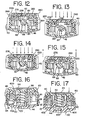
- the axial movement of the cap member 20, 220, 1020, 2020 relative to the base member 40 is bounded or constrained by the engagement of the engagement members with the top of the base member pockets (or the base member rim) at a fully extended position and by engagement of a bottom rim 21, 221, 1021, 2021 of the cap member skirt with the upper surface of the bottom portion at the bottom of the stroke as shown for example in FIGS. 12-15 .
- the engagement members can alternatively be formed on the base member skirt so as to engage pockets or openings, or a rim (or like protrusion), formed on the cap member skirt.
- a spring 100 is disposed between the cap member and the base member.
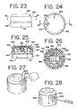
- the spring is preferably disposed in a downwardly extending hub portion 30, 230 of the cap member (shown in FIGS. 4 and 6 ) and an upwardly extending hub portion 44 (shown in FIGS. 10 , 16 and 17 ) of the base member, which are received one in the other.
- a spring 300 is disposed between the cap member and base member and is of such a size that the coils are positioned adjacent the inner circumferential surface of the cap member skirt 392.
- the spring 100, 300 functions as a return mechanism and biases the cap member 60, 260, 360 upwardly in the base member such that the engagement members 28, 228 of the cap member engage the upper portion of the pockets of the base member.
- a compression spring is shown in the Figures, it should be understood that a belleville washer, cantilever, torsion, leaf and/or tension springs would also work to bias the cap member upwardly into engagement with the base member.
- the springs can be made of metal or plastic.
- the return mechanism acting between the cap member and base member includes a plurality of resilient arm members 400, 2400, 6400 extending downwardly from the cap member.
- the cap member As the cap member is moved toward the base member, one or more of the arm members engages a ramped biasing surface 402, 6401 formed along an outer portion of the hub portion 44, or along the inside of the circumferential skirt 94.
- the ramped biasing surface biases one or more of the resilient arm members outwardly as the cap member moves toward the base member.
- six arm members 400 are arranged circumferentially around the hub portion 30.
- each arm member 1400 is arranged in an "X" pattern around the hub 1030 so as to conserve space and provide additional room under the cap member 1020.
- Corresponding ramps, or ramped biasing surfaces are similarlv arranged in the base member 1140.
- the arm members 6400 are integrally formed in the circumferential skirt 6092 of the cap member and also adjacent various guide members 6571, 6569. The guide members are received in guides 6579, 6581, 6591 formed in the base member. Referring to FIGS.
- one of the guide members 6569 is shaped to be received in only one of the guides 6581, such that the cap member can be properly installed with the various indicator members connected thereto aligned with the pawl 48 formed in the base member.
- the guides and guide members further act as key members to prevent the cap member from rotating relative to the base member.
- the guides can take any shape, for example rectangular or T-shaped.
- a pair of guide members 6583, 6585 have different shapes, e.g., diameters, that are received in matingly shaped guides formed in the base member. Again, the unique shapes of the guide members and guides ensures that the cap member is properly aligned with the base member as those components are being secured one to the other.
- the resilient arm member(s) act as cantilever springs to bias the cap member away from the base member when the cap member is released by the user.
- the resilient arm members can also be formed on the base member so as to engage a ramped surface formed on the cap member.
- the spring and resilient arm members can be used together, as shown in FIGS. 16 and 17 , or separately.
- one or more arm members and/or ramps may be used, with the size and shape of the arm member and/or ramp members being modified to provide more space between the cap member and base member.
- a key member 32, 232, or alignment rib extends radially from the cap member hub portion 30, 230.
- a key hole 47, or slot is formed in a radially extending portion of the hub portion 44 of the base member. The slot extends radially from the opening in the hub portion.
- a dosage indicator member 60, 260, 1060, 2060 is rotatably mounted in the cap member 20, 220, 1020, 2020 about an axis substantially parallel to the axial movement of the cap member relative to the base member.
- the indicator member is generally open in the middle and includes a top portion 76, 276, 1076, 2076 having an upper surface 62, 262 that rotatably slides along a bottom surface of the top portion of the cap member.
- the indicator member can be mounted on the outside of the cap member with a viewing window formed in the indicator member for viewing indicia applied to the top of the cap member.
- the indicator member 60, 260, 1060, 2060 includes a circumferential skirt 74, 274, 1074, 2074 depending downwardly from the top portion.
- a plurality of protrusions 26, 226, or engagement tab members extend from an inner circumferential surface of the cap member skirt and engage a rim 64, 264 formed on the bottom of the indicator member skirt.
- the indicator member can include an engagement member, or rim, that engages a groove or similar opening in the cap member. In this way, the indicator member is secured to the cap member so as to prevent axial movement therebetween but where the indicator member is permitted to rotate relative to the cap member.
- the indicator member is installed by snap-fitting the indicator member within the cap member.
- the indicator member could alternatively be rotatably mounted on the cap member hub portion (having a portion of the key member cut away), or on a similar axle secured to the cap member.
- a plate member 380 holds the indicator member 360 against the inner surface of the top portion of the cap member 320, wherein the spring 300 engages a bottom surface of the plate member 380 to bias a top portion 398 of the plate member against the cap member 320 and the cap member away from the base member.
- the indicator member 360 is nested in the recess formed between an outer flat portion of the plate member and the bottom surface of the cap member.
- the drive assembly is mounted to the plate member 380 by inserting axle 384 through openings in downwardly extending walls 388 of the plate member. An enlarged portion 396 on the end of the axle engages one of the walls, while the ratchet wheel 382 and drive member 386 are mounted to the other end of the axle to complete the assembly. A top portion of the plate member abuts the cap member.
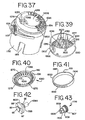
- the indicator member 60, 260, 1060, 2060 has a plurality of inwardly facing teeth 66, 266, 1066,2066 formed around the inner circumference of the skirt. As shown in FIGS. 5 , 6 , and 40 , the teeth are preferably formed about only a portion of the circumference, such that a gap 1061 is formed therebetween.
- the indicator member 360 has a plurality of teeth 366 formed radially inwardly about an inner rim of an opening formed in the indicator member, which is configured as a relatively flat ring that does not include a skirt.
- the plurality of teeth 466 extend axially downwardly from a ring-like indicator member 460.
- the indicator member 60, 2060 includes a plurality of indentations 68, 2068 formed about the outer circumferential surface of the skirt 74, 2074.
- the cap member includes a pair of upwardly extending resilient indexing members 22, 2022 each having an end portion that engages one of the indentations so as to releasably engage the indicator member and prevent rotation therebetween.
- the angular distance between the indentations 68, 2068 is substantially the same as the angular distance between the plurality of indicator member teeth 66, 2066. In this way, the indexing member selectively engages the next indentation upon each incremental advancement of the indicator member defined by the distance between adjacent teeth.
- the indentations are preferably formed as ratchet teeth which only permit one-way rotation of the indicator member 2060 relative to the cap member.
- the indentations and indexing member are reversed, i.e ., the indentations 224, 1224 are formed about an inner circumferential surface of the cap member skirt and, and shown in FIG 6 , an indexing member 270 depends downwardly from the indicator member in a void formed in the skirt of the indicator member, or, as shown in FIG. 38 , a pair of index members 1270 are configured as flexible arms formed along a rim portion 1078 along the bottom edge of the skirt 1074.
- the interaction between the index members 1270 and the indentations 1224 function to index the indicator member by holding it in place between actuations of the cap member and also to prevent the backward rotation of the indicator member 1060.
- one or more index members can be engaged with a plurality of indentations, preferably formed as ratchet teeth, to control the rotational movement of the indicator member, regardless of whether the index members or indentations are formed on the cap member or the indicator member.
- the plate member 380 includes a resilient indexing member 370 that engages one of the plurality of teeth 366 to selectively engage the indicator member so as to prevent the inadvertent rotation thereof.
- the indexing member can extend from the cap member.
- primary dosage indicia 72,172 in the form of numbers or color codings are provided on the top surface of the indicator member and are visible to the user through the viewing window 34, 59 provided in the top of the cap member.
- a zero is positioned adjacent a rectangular viewing window 334, preferably by permanent etching, to indicate a multiplication by ten of the indicia visible in the viewing window.
- One and two digit primary dosage indicia 372 are formed on the top of the indicator member 360 such that a three digit number is indicated to the user.
- the viewing window 534 is formed in an upper portion of the downwardly depending circumferential skirt 592 of the cap member.
- the primary dosage indicia are applied to the outer circumferential surface of the indicator member skirt 574 so as to be visible through the window.
- a rim 542 of the base member is preferably scalloped in alignment with the viewing window 534 to provide an unobstructed view of the indicia and to inform the user as to the location of the viewing window.
- a segmented color grid 172 displayed in the viewing window could turn from green, indicating a full container, to yellow, indicating an intermediate capacity, and finally to red, indicating an empty container.
- the indicia can be formed integrally with the counter member, or applied thereto by means of paint, dye, etching, pad printing, hot stamping or adhesive labels.
- the numbers can be arranged to go from 0 (or some beginning number) to the predetermined number of available doses such that a display of that number to the user indicates that the container should be replaced, or, conversely, to go from the starting predetermined number to 0 (or some ending number), which again indicates to the user that the container should be replaced.
- the indicator member is made of acrylonitrile butadiene styrene ("ABS"), which is receptive to certain alternative processes of printing or applying the indicia, including pad printing and hot stamping.
- ABS acrylonitrile butadiene styrene
- the cap member and base member are preferably made of a hard plastic material such as Acetal.
- one or both of the base member and cap member can be made of polycarbonate.
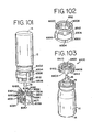
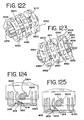
- a drive mechanism is shown as including a drive assembly 80.
- the drive assembly includes a ratchet wheel 82 coaxially mounted to a drive member 86 on an axle 84.
- the ratchet wheel, drive member and axle can be made separately, with the ratchet wheel and drive member then mounted on the axle, or all three parts can be integrally molded as a one-piece component.
- the drive assembly is preferably made of hard plastic material such as Acetel.
- the drive assembly further includes a second primary dosage indicator member 1800 coaxially mounted with and between the drive member 86 and ratchet wheel 82.
- the indicator member 1800 is configured as a wheel and preferably includes primary dosage indicia positioned around the peripheral surface 1802 thereof.
- the indicia are comprised of consecutive numerals running from 0 to 9.
- the drive assembly includes a ratchet wheel 82 coaxially mounted with an indicator member 1800.
- the drive member 86 is formed separately from the ratchet wheel and indicator member and includes a single tooth 89 that is dimensioned to be received in a groove 1801 formed in a collar 1082 extending axially from the indicator member 1800.
- the tooth 89 of the drive member 86 is received in the groove 1801 of the collar and can be moved axially with respect to the collar, ratchet wheel and indicator member.
- the ratchet wheel 82 includes a plurality of teeth 88 (preferably ten) formed around its periphery. Each of the teeth includes an engagement surface 89 and a tapered surface 87.
- the drive member 86 whether integrally formed with the ratchet wheel or separately connected thereto, includes a single tooth 81 extending radially from the axle 84, or drive member collar.
- the drive assembly is mounted to the cap member by engaging opposite ends of the axle 84 with downwardly extending hub portions 36, 236, 2236 such that the axle, ratchet wheel and drive member rotate about an axis substantially perpendicular to the axial movement of the cap member relative to the base member and to the axis of rotation of the indicator member.
- the drive assembly can be mounted to the base member, along with the indicator member, in a similar manner.
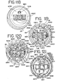
- the axle 84 is received in a single hub 1036, or flexible snap enclosure rib.
- the drive assembly further includes a ramp 1083, which ramps up to a plurality of radially extending teeth 1085 formed around the rotational axis of the drive assembly.
- a larger diameter axle 1084 extends outwardly from the teeth.
- a reset member 1106 includes a grippable wheel portion 1107 and a collar 1109 that is dimensioned to be received in a laterally facing opening 1302 formed in the skirt of the cap member.
- a bearing support 1300 is formed around the periphery of the opening so as to provide support for the collar.
- the reset member 1106 further includes four flexible, resilient fingers 1304 extending axially from the collar 1109. Each finger 1304 includes an engagement portion 1306 extending radially inward from the end of the finger. The engagement portion is shaped to engage one of the teeth 1085 formed on the drive assembly.
- a protrusion 1308, or rib, is formed on one of the fingers so as to extend radially outward therefrom.
- the protrusion 1308 acts as a drive portion and engages a downwardly depending protrusion 1310 formed on the bottom of the indicator member adjacent the gap 1061 formed between the teeth on the indicator member, as shown in FIG. 40 .
- the protrusion 1310 is positioned so as to be at the angular midpoint between the two teeth spanning the gap.
- the drive mechanism further includes a pawl member 48, shown as a flexible rod or finger, which extends upwardly from the bottom portion of the base member and selectively engages one of the teeth of the ratchet wheel.
- the base member with the pawl are referred to and function as an actuator for the indicating device as the base is connected to and engaged by the container.
- the pawl member can be moveably secured to the cap member and extend through the base member to engage the top of the container, such that the axial movement of the cap member toward the container causes the pawl to move toward the ratchet wheel and engage one of the teeth thereon as described below.
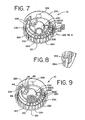
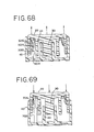
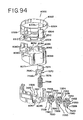
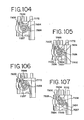
- each of the indicator members includes an indicator wheel 6558 having a circumferential skirt 6559 with an outer circumferential surface 6560 on which indicia (shown as numbers) are applied, and a ratchet gear 6552 coaxially mounted with the indicator wheel.
- a plurality of primary viewing windows 6021 are formed in the top portion of the cap member such that the indicia are visible in the windows.
- first and second rings are visible in a viewing window, as shown for example in U.S. Patent No. 6,283,365 . If should be understood that a single window could be provided, with all of the indicia visible through the window.
- the indicator wheel and ratchet gear have an opening shaped to receive an axle.
- the middle indicator member is integrally formed with an axle portion extending from opposites sides thereof, with the other indicator wheels mounted thereon.
- the axle can be formed with an asymmetrical cross-section, e.g., a T-shaped cross-section, such that the axle is non-rotatably secured to the indicator wheels.
- the ratchet gear 6552 includes a plurality of teeth 6554 formed around its periphery.
- the ratchet gear is preferably integrally molded with the indicator wheel, although it should be understood that the gear and wheel can be made separately and thereafter attached one to the other by welding, adhesive and the like.
- a resilient advancement member 6600 extends from the indicator wheel.
- the advancement member 6600 includes a tooth portion 6604 having an engagement surface.
- the three indicator members are coaxially mounted such that the tooth portion 6604 of the advancement member of a first indicator member overlies the ratchet gear teeth 6652 of the second indicator member, and such that the tooth portion of the advancement member of the second indicator member overlies the ratchet gear teeth of the third indicator member.
- the third indicator member does not require an advancement member, although for the sake of simplicity in manufacturing, a modular indicator member with the same indicia applied thereto and the same advancement member formed thereon can be used for each of the first, second and third indicator members.
- one or more indicator members may be used to provide an indication of dosages used or available, and that the three indicator members shown in the Figures is meant to be illustrative, rather than limiting.
- a plurality of indicator members refers to any number of indicator members greater than one.
- the advancement member 6600 includes a first end connected to a planar side portion or hub of the indicator wheel.
- the advancement member includes a curved resilient portion having a free end with the tooth portion 6604 formed on the end thereof.
- Indicia preferably in the form of numbers, are applied to the circumferential surface 6560 of the skirt.
- the indicia can take any form as herein described, including color coding, text, etc. It should be understood that the advancement member, indicator wheel and ratchet gear can take any of the forms described herein.
- an actuator member 48 is configured as a resilient arm member that extends upwardly from the base member and terminates in an end portion shaped to selectively engage at least one of the teeth of the ratchet gear of the first indicator member.
- the cap member has at least a pair of engagement members 6573 formed integrally therewith and including ramped surfaces.
- a plurality of non-return members 6900 extend from the cap member and selectively engage the ratchet gears to ensure unidirectional rotation of the primary indicator members.
- the engagement members and non-return members are shown as being formed in the cap member, it should be understood that the primary indicator members could be mounted in the base member, with the engagement members and non-return members also formed therein, and with the actuator extending from the cap member.
- arm members serve as a combined engagement member and non-return member.
- the arm member functions as a non-return member and includes an end portion that is biased away from the teeth on the ratchet gear as the actuator member, or adjacent indicator member with its advancement member, is actuated to advance the ratchet gear.
- the arm member snaps back so that the end portion engages one of the teeth of the ratchet gear so as to ensure that the rotation of the ratchet gear is unidirectional.
- the arm member overlying the ratchet gears of the second and third indicator members also serves as an engagement member that selectively engages the advancement members connected to the indicator members.
- each indicator wheel 6550 includes a ratchet gear 6552 and an indexing gear 6551 disposed on opposite sides of the respective wheels.
- the indexing gear 6551 is engaged and indexed by the return member, otherwise referred to as the indexing member.
- a pair of advancing gears 6533 are rotatable mounted on an axle 6537 parallel to the axis of rotation of the indicator wheels.
- the gears 6533 are independently rotatable on the axle.
- the axle 6537 is supported by a pair of bearing supports 6539 extending from the cap member.
- the indicator wheels each include an advancement tooth 6535 that engages the advancement gear upon one rotation of the indicator wheel.
- the first advancement gear 6533 is meshed with the ratchet gear on the adjacent second indicator wheel. As the advancement gear 6533 is advanced by the advancement tooth 6535, the gear advances the adjacent indicator wheel an incremental amount. The advancement of the third indicator wheel is made by way of the second advancement gear being advanced by an advancement tooth of the second indicator wheel.
- the indicia are preferably formed around the circumferential surface 6560 of the indicator wheel in the form of numbers ranging from 0 to 9, with the ratchet gear on the indicator member having 10 teeth.
- the three, or more or less, indicator members can be preset to the maximum number of dosages contained within the container, with the indicia, or in this case numbers, arranged about the periphery of the indicator wheel, such that successive, sequential actuations of the container cause the indicator members to count down.
- the indicator members are assembled such that the zero (0) of each indicator member is displayed in the viewing window to the user.
- the container is then actuated by the user such that the first indicator member rotates within the housing to sequentially display the number of doses that have been dispensed from 1 to 9.
- the indicator member completes a single revolution, by virtue of the ten teeth preferably formed about the ratchet gear which correspond to the predetermined number of actuations, and causes the second indicator member to advance one number from 0 to 1 as the first indicator member again displays a 0 such that the two members together indicate that 10 dosages have been dispensed.
- the first indicator member is again rotated by successive actuations until another single rotation is completed to further rotate the second indicator to reveal the 2, so as to indicate that 20 dosages have been dispensed.
- the third indicator member is advanced to reveal a 1 in the viewing window with the first and second indicator members revealing a 0, and so on.
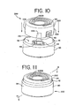
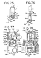
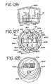
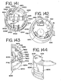
- the user depresses the cap 220 member from a fully extended position (see FIG. 12 ) toward the base member such that the cap member bottoms out in the base member at the bottom of the stroke ( FIG. 14 ) and such that the base member imparts an axial load on the container until a metered dosage is dispensed therefrom.
- the biasing force of the spring 100 shown in FIG. 6
- alternative return mechanism such as the resilient arm members which act as springs, is less than the biasing force of the spring located in the metering valve of the container, such that the cap member first bottoms out in the base member with the container then being moved downwardly in the housing until a metered dose is dispensed.
- the pawl 48 selectively engages the engagement surface 89 of one of the ratchet wheel teeth and rotates the ratchet wheel.
- the tapered surface 87 of one of the teeth formed on the ratchet wheel simultaneously biases the non-return member 238 outwardly until it selectively engages the next tooth near the bottom of the stroke.
- the return member provides an audible click as it engages the next tooth. The user then releases the cap member whereinafter the spring 100 (shown in FIG. 6 ), or similar return mechanism, biases the cap member 220 away from the base member 40 until the engagement member engages the base portion at the top of the stroke as shown in FIG. 15 .
- the container When the cap member is released by the user, the container is biased upwardly within the housing along the longitudinal axis such that the valve stem is moved to the closed position within the container. Simultaneously, as the cap member is released and allowed to move away from the base member, the pawl 48 is biased outwardly by the tapered surface 87 of one of the teeth on the ratchet wheel as the non-return member 238 prevents a backwards rotation thereof so as to maintain a unidirectional rotation of the ratchet wheel. At the top of the stroke (shown in FIG. 15 ), the pawl 48 is again placed in position for selective engagement with one of the teeth of the ratchet wheel. Again, the pawl provides an audible click as it engages the next tooth.
- the non-return member makes a clicking sound as it slides over one or more ratchet teeth
- the pawl member also makes a clicking sound as it slides over one or more ratchet teeth.
- the ratchet wheel 82, and connected drive member 86 are advanced an incremental amount for every actuation of the container and the attendant release of medicament. The incremental amount is defined by and dependent on the number of teeth formed about the periphery of the ratchet wheel.
- the ratchet wheel When formed with ten teeth, as shown in the preferred embodiment, the ratchet wheel will make one full revolution for every ten actuations of the indicator device and container, or a tenth of a revolution for each actuation.
- the ratchet wheel can be provided with various numbers of teeth formed about its periphery such that the more or less axial movements or actuations of the container are required to make one full rotation of the ratchet wheel.
- the operation of the ratchet wheel can be reversed.
- the pawl is biased outwardly by the tapered surface of one of the ratchet wheel teeth on the downstroke. At the bottom of the stroke, the pawl is biased into engagement with one of the teeth.
- the spring, or equivalent return mechanism biases the cap member upwardly within the base member along the longitudinal axis such that the pawl member engages one of the teeth and thereby rotates the ratchet wheel an incremental amount.
- the non-return member maintains the rotational position of the ratchet wheel on the downstroke.
- the drive member 86 is shown as preferably having a single tooth 81 or segment. Therefore, upon every tenth actuation, the drive member 86 is rotated such that the tooth selectively engages one of the teeth 266 formed on the indicator member so as to rotate the indicator member an incremental amount.
- the incremental amount of rotation is defined by the distance between adjacent teeth, otherwise defined as the circular pitch of the teeth. In this way, the drive member is selectively engaged with at least one of the teeth of the indicator member after and upon a predetermined number of axial movements of the cap member relative to the base member so as to rotate the indicator member the incremental amount.
- the predetermined of number axial movements required to cause the indicator member to rotate is defined by and dependent upon the reduction ratio of the ratchet wheel and drive member, which, in turn, is defined by dividing the number of teeth formed on the ratchet wheel by the number of teeth formed on the drive member. For example, as shown in the preferred embodiment, a ratchet wheel having ten teeth and a drive member having one tooth will result in an incremental movement of the indicator member, otherwise defined as the advancement of one tooth of the indicator member, upon every ten axial movements. Similarly, if the drive member had four teeth, and the ratchet wheel twenty, the predetermined number would equate to five axial movements, and so on. A one-to-one gear ratio would result in a predetermined number of one axial movement, wherein the indicator member would be moved upon every axial movement.
- the indicator member 260 and drive member 86 are shown prior to an initial actuation or use by the user.
- the drive member tooth is positioned adjacent the first tooth 266 on the indicator member.
- the ratchet wheel comprises ten teeth
- ten actuations are required before the tooth 81 engages the first tooth 266 on the indicator member as shown in FIG. 21 .
- the indicator has completed a single cycle equal to the number of predetermined number of axial movements, which results or culminates in the incremental movement of the indicator member.
- the cycle is then repeated (by again making the predetermined number of axial movements) so as to again culminate in the incremental movement of the indicator member.
- numerical indicia are applied in increments of ten to correlate to the preferred embodiment requiring ten axial movements for one incremental advancement of the indicator wheel.
- the ratchet wheel and drive member with their reduction ratio provide a simple but reliable mechanism for advancing the indicator member.
- the indicator member can be made with fewer teeth than if it were required to advance upon every actuation of the indicator member and container.
- the indicator member make only a single revolution (single-cycle) corresponding to a complete evacuation of medicament from the container.
- the ratchet wheel and drive member when a large number of doses (on the order of 200 or more) are contained within the container, it is important for the ratchet wheel and drive member to provide a relatively high reduction ratio, such that 200 linear reciprocal movements of the cap member and container correspond to one or less revolutions of the indicator member.
- the indicator member can be made with coarser teeth at less cost.
- larger coarser teeth interacting with a relatively large drive member tooth helps to improve the accuracy of the device as those parts mesh.
- the mechanism, and its attendant reduction ratio permits the indicator member to make only a single revolution during the life of the container, i.e., until it is emptied, even when the container contains a relatively large number of metered doses (on the order of 200 or more doses).
- This single revolution corresponds to a usage cycle, which is defined as the movement of the dosage indicator from an initial reading, which indicates that the container is full, to a final reading, which indicates that the container should be replaced.
- a usage cycle which is defined as the movement of the dosage indicator from an initial reading, which indicates that the container is full, to a final reading, which indicates that the container should be replaced.
- the indicator member if initially set to a smaller number of dosages, may make less than a complete revolution in completing a usage cycle.
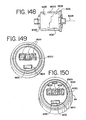
- the viewing window 1034, 2034 is large enough such that the first and second dosage indicator members 1060, 2060, 1800 with their indicia are visible therein.
- the indicator member 1800 rotates with each actuation of the cap member 1020, 2020 relative to the base member 1040, 2040 as the ratchet wheel 82 is driven by the pawl member.
- the indicator member 1800 rotates about an axis substantially perpendicular to the axial movement of the cap member relative to the base member and to the rotational axis of the indicator member 1060, 2060.
- the indicator member 1800 is advanced upon each actuation and provides indicia visible to the user to notify them of such advancement.
- the indicator member 1800 completes a cycle, or rotation, the indicator member 1060, 2060 is advanced one increment by the drive member 86 and the indicator member 1800 begins another cycle. In this way, the user is advised as to each actuation of the indicating device and the attendant dispensement of a dosage from the attached container.
- the indicator member 60, 260, 1060 is not advanced after the drive member engages the last tooth, even when the cap member is repeatedly moved to actuate the container. This ensures that the indicator member cannot be advanced past the last indicia indicating that the container is empty, or should otherwise be replaced, to a first indicia indicating that the container is full, so as to confuse the user.
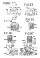
- the drive member has an additional finger 3002, or stop member circumferentially spaced from the single tooth 81.
- additional finger 3002 has a lesser radial length than the tooth 81 such that it clears the teeth 66 formed on the indicator member 60 as the drive member is rotated by actuations of the container, and as it is engaged with the indicator member after and upon the predetermined number of movements of the cap member relative to the base member.
- the indicator member has a corresponding stop member 3004 spaced circumferentially from the last tooth 66.
- the stop member preferably extends downwardly from the upper surface a greater extent and is longer than the teeth 66.
- the stop member 3004 has a stop surface 3006 formed at an angle of about 15 degrees from the horizontal, such that it slopes up and away from the drive member stop member 3002.
- the angle is greater than 0 degrees from the horizontal such that the stop member 3002 on the drive member cannot slip past the stop surface 3006 and thereby allow subsequent rotations of the ratchet wheel 82.
- the user moves the cap member 20 toward the base member 40 a first predetermined number of times corresponding to the total number of metered dosages, such that the indicator member 60 is rotated between an initial position, wherein indicia indicate to the user that the container is full, and a final position, wherein the indicia indicate to the user that the container should be replaced.
- the drive member and in particular, the tooth 81, is successively engaged with at least one of the teeth 66 of the indicator member upon a second predetermined number of axial movements of the cap member 20 relative to the base member 40, wherein the indicator member is moved an incremental amount.
- the first predetermined number of actuations is greater than and some multiple of the second predetermined number of actuations.
- the first and second predetermined number of actuations can be equal, preferably with the second predetermined number being greater than one.
- the drive tooth 81 moves indicator member 60 a final incremental amount as the pawl 48 engages one of the teeth 89 and moves the ratchet wheel 82, and thereby rotates the stop member 3004 formed on the indicator member into vertical alignment over and with the stop member 3002 formed on the drive member.
- the stop members 3002, 3004 must be dimensioned and located on the drive member and indicator member respectively and relative to the other teeth on the drive member and indicator member so as to allow the stop member 3004 to pass over the stop member 3002 during the final actuation. In this location, with the stop members 3002, 3004 engaged, the drive member 86, and connected ratchet wheel 82, can no longer be rotated relative to the cap member 20 upon subsequent actuations.
- the cap member 20 is again moved toward the base member 40.
- the drive member is locked and unable to rotate, the engagement surface 89 of one of the teeth on the ratchet wheel engages the pawl 48 and deforms the pawl, preferably by bending, as the cap member 20 moves toward the base member 40.
- neither the non-return member 238 nor the pawl 48 moves past any teeth of the ratchet wheel 82 and the audible click is thereby eliminated.
- an auxiliary warning system or indicia, is provided to inform the user that the final predetermined dose of medication has been dispensed, and/or that the container should be replaced.
- the container can still be actuated, such that if certain residual doses were available therein they can be dispensed in an emergency situation.
- the pawl 48 is configured to bend over after the final predetermined actuation such that it does not provide a false audible indication that the container does not need to be replaced, e.g., that additional doses are available upon subsequent actuations after the next subsequent actuation following the final predetermined actuation.
- the bent pawl 48 prevents tampering and unintended resetting by the user.
- the pawl 48 has fillets 3008 formed along its base each having a preferred radius of about 1.40 mm, or preferably a radius greater than a minimum value required to prevent stress concentrations in the plastic during the bending process that occurs during the next subsequent actuation or movement of the cap member after the final predetermined actuation of the container.
- the overall height of the pawl is preferably about 5.20 mm.
- the width of a pawl head 3020 is preferably about 1.80 mm, and the width of a stem 3018 is preferably about 0.65 mm.
- the overall height of the pawl 48 and the width or thickness (or diameter if round) of the stem 3018 are preferably greater than minimum permissible values that will provide the pawl with enough strength and resistance to buckling during normal operation, but which allows the pawl to bend during the next subsequent actuation of the container and movement of the cap member after the final predetermined actuation of the container.
- the width of the head 3020 of the pawl allows it to function during the normal operation of the device, and further allows it to be nested with the ratchet wheel 82 after the pawl is bent when the cap member 20 and ratchet wheel 82 are at the bottom of subsequent strokes after the final predetermined actuation.
- the various preferred dimensions described herein can be scaled up or down depending on the size of the overall indicator and force required to actuate the container, and the corresponding force of the return springs.
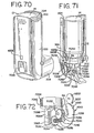
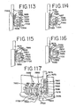
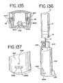
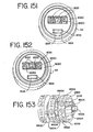
- the indicating device includes a lock device.
- the base member includes a first lock member 702, configured as a post member extending upwardly from the bottom of the base member.
- the indicator member 760 includes a second lock member 704, shown in FIG. 35 as a radial extension of one of the plurality of teeth 776 formed around the circumference of the indicator member, and shown in FIG. 69 as a separate post member.
- the cap member In operation, the cap member is moved towards and away from the base member between a fully extended position, wherein the cap member is distal to the base member, and a bottom of the stroke position, wherein the cap member is proximate the base member, so as to rotate the indicator member as described above.
- the first lock member 702 is positioned inside the inner diametrical surface of the plurality of teeth so as to not interfere therewith as it is moved into the recess formed by the indicator member as shown in FIG. 33 .
- the second lock member 704 is rotated over the first lock member 702 as shown in FIGS. 35, 36 and 69 .
- the cap member cannot be moved toward the base member.
- one or both of the first and second lock members 702, 704 are biased against the other such that they snap into position, one over the other, upon completion of the final upstroke.
- the immobility of the cap member provides visual and physical secondary indicia that the container should be replaced, and further prevents the mechanism from clicking or the indicator member from moving, thereby providing both a visual as well as an audible indication that the container should be replaced.
- a post member may extend from the cap member so as to engage a stepped surface in the base member, which functions as a stop member.
- the pawl 48 can be made sufficiently robust, for example by thickening the stem, such that when it is used with the stop members 3002, 3004, the pawl 48 engages the ratchet wheel 82 and prevents the cap member 20 from being moved toward the base member 40, rather than bending or buckling as described above with respect to another preferred embodiment.
- the immobility of the cap member 20 relative to the base member 40, and the elimination of any clicking sound provides further indicia to the user that the container should be replaced.
- the lock member can extend from the cap member and engage a corresponding lock member on the base member.
- the lock device includes a pair of catch members 3010, 3012 formed on the indicator member 60 and the base member 40 respectively.
- one of the catch members can extend from the cap member and engage a catch member formed on the base member.
- each catch member 3010, 3012 includes an end portion 3014, 3016 having opposing hooks, which engage at the bottom of the final predetermined stroke of the cap member 20 relative to the base member 40. In this position, the cap member 20 cannot be moved away from the base member 40.
- the immobility of the cap member provides a secondary indicia that the container should be replaced, and further prevents the mechanism from clicking or the indicator member from moving, thereby providing both a visual as well as an audible indication that the container should be replaced.
- the size and shape of the first and second catch members can be varied.
- the catch members can be configured as any two members that engage, for example by using adhesives, hook and loop type fasteners, detents, etc.
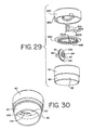
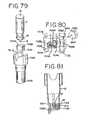
- a reset wheel 106 is coaxially mounted with the ratchet wheel 82 and drive member 86.
- the outer periphery 108 of the wheel which includes a plurality of teeth for gripping by the user's thumb, is exposed as it extends through the bottom surface 50 of the base member.
- the reset wheel can be exposed by extending from other portions of the indicator device for access by the user. The user rotates the reset wheel 106 to manually rotate the indicator member to its original starting position, or any other desired setting, without having to move the cap member relative to the base member. In this way, the indicator member can be recycled for use on a new container, or can be moved to the proper setting prior to installing the indicating device on the container.
- the same indicating device can be used with various containers containing varying numbers of metered dosages of medicament.
- the force of the indexing member against the indentations in one of the cap member and indicator member is overcome such that the indexing member repeatedly moves into and out of engagement with the indentations as the indicator member is rotated by the user to the desired setting.
- This movement is similar to the movement of the indexing member occurring upon each incremental advancement of the indicator member relative to the cap member.
- the reset wheel of FIGS. 29 and 30 is used with an indicator member having teeth formed about its entire periphery, such that the indicator wheel need only be moved a few teeth (one or more) to return it to the zero (or full, e.g., 200) position.
- the reset wheel can be used with or without the lock device described above, since the wheel can be used to move or rotate the indicator wheel independent of any axial movement between the cap member and base member.
- a reset selector member 602 is mounted to the end of the axle and is exposed in an opening 604 in the side or skirt 694 of the base member.
- the reset selector member 602 is mounted on the axle.
- the selector member 602 is provided with a slot adapted to receive the head of a screw driver or like tool, which can be actuated by the user to rotate the axle, coaxially mounted drive member and indicator member until the desired indicia are visible in the viewing window. This feature can be valuable for resetting an indicating device for use on a new container, or for initially setting the device for the proper number of doses contained in the container.
- recesses and/or protrusions other than the disclosed slot can be exposed on the selector member to allow the user to grip or otherwise operably engage the selector member and to thereafter rotate the indicator member.
- the opening in the base member could be positioned anywhere along the longitudinal path of the axle as the cap member moves relative to the base member so as to expose the selector member when aligned with the opening.
- a selector window 806 is formed in the top of the cap member.
- a reset selector member 802 configured as a protrusion or like grippable member, is exposed in the window as the indicator member is rotated to the empty position.
- the plurality of teeth are formed only around a portion of the periphery of the indicator member so as to leave a gap between the first and last tooth.
- the selector window 806 is preferably of such length that the user can move the reset selector member 802 within the window until the first tooth is again in position for engagement with the drive member. It should be understood, however, that the reset selector member can also be used with an indicator member having teeth formed around the entire periphery of the member.
- a plurality of reset members or a similar grippable surface, configured for example as a plurality of notches or teeth, can be formed around the entire periphery of the indicator member and exposed in a selector window, or alternatively, in the viewing window.
- the indicator wheel can be rotated to expose different indicia at any time simply by engaging the reset selector members on the indicator member with the user's thumb or like member.
- an opening, or selector window 906 is provided in the top of the cap member.
- a thin tool such as a paper clip, is inserted through the opening to bias the resilient indexing member 370 out of engagement with the indicator member.
- the user can then operably engage the indicator member with their finger or the like, either through the viewing window or a selector window, to move the indicator member to the desired setting.
- the reset member in yet another alternative embodiment, shown in FIG. 43 , is pulled axially outward with respect thereto from a disengaged position, where the engagement portions 1306 of the flexible fingers 1304 are positioned circumferentially around the axle 84, to an engaged reset position, such that the engagement portions 1306 of the flexible fingers are biased outwardly as they ride up the ramp 1083 and are thereafter moved into engagement with the teeth 1085 formed around the axle of the drive assembly.
- the user then rotates the reset member 1106 about a rotation axis, which is substantially perpendicular to the axial movement of the cap member relative to the base member.
- the reset member As the reset member is rotated, the protrusion 1308 on the flexible fingers is brought into engagement with the protrusion 1310 on the indicator member 1060 so as to rotate the indicator member an incremental amount and thereby bring the first tooth on the other side of the gap 1061 into position for engagement by the drive member, thus bridging the gap 1061 between the teeth of the indicator member.
- the drive member tooth 89 engages the teeth 1066 of the indicator member, and the reset member can be rotated to manually drive the indicator member, or indicator members, to the desired preset condition.
- the indicator members can be reset to indicate 200 dosages for use with a container having 200 dosages.
- the engagement portions 1306 and/or teeth 1085 formed on the axle of the drive assembly are configured to allow rotation of the drive member in only one direction. Therefore, rotation of the reset wheel in an opposite direction will not effect a rotation of the drive member in that same direction as the flexible fingers, with their engagement portions, will simply slide over the teeth formed about the axle. This one-way rotation prevents the drive member from engaging and rotating the indicator member in an opposite direction, which direction is opposed both by the non-return member engaging the ratchet wheel, and the one-way indexing interface between the cap member and indicator member.
- the drive assembly is installed in a vertical manner such that the axle 84 is received in the flexible snap enclosure 1036. Once the drive assembly is snapped in place, the reset member 1106 is inserted through the opening in the cap member and over the axle 1084 until the fingers eventually are disposed around the axle 84 in the disengaged position. In this way, the reset member, which is supported by the bearing surface 1300 of the cap member, further supports the drive assembly.
- the indicator member 2060 has a plurality of teeth extending around the entire circumference thereof. At least one of the teeth 2067 has a cut-away portion 2069 aligned with the tooth 89 of the drive member. Accordingly, at the end of a cycle, the drive member is positioned in a disengaged position where even repetitive actuations of the indicating device do not lead to the advancement of the indicator member as the drive member, with its one or more teeth 89, merely passes through the cut-away portion 2069 of the tooth, with which it is aligned. In this embodiment, however, the drive member 86 is axially moveable with respect to the indicator member 1800 and ratchet wheel 82.
- a reset member 2106 includes a grippable wheel 2107 connected to a drive shaft 2109.
- the end of the drive shaft includes a plurality of teeth 2306, that engage slots 2308 or openings dimensioned to receive the teeth formed in one end of the drive member 86.
- the drive member is installed on the shaft of the reset wheel such that the teeth 2306 formed on the end thereof engage the slots 2308 formed in the drive member. The drive member is then inserted into the groove 1801 of the collar 1082 extending from the indicator member.
- the user pulls the reset member 1206 axially outward so as to move axially the drive member 86 from a disengaged position, where the drive member tooth 89, or teeth, is aligned with the cut-away portion 2069 of the tooth on the indicator member, to an engaged or reset position, where the drive member tooth is brought into engagement with the portion 2067 of the tooth that is not cut-away.
- the reset position the user rotates the reset wheel 2107 and connected drive member 86 so as to advance the indicator member 2060, or indicator members, to the desired setting independent of the axial movement of the cap member relative to the base member.
- the reset wheel is recessed between a pair of tapered flanges formed around the circumference of the base member.
- the indicator member 2060 includes a cover portion 2087 that extends radially inward from the top portion of the indicator member.
- the cover portion is brought into alignment with the viewing window at the end of the usage cycle such that the indicator 1800, which can continue to be spun beneath the cover portion is not visible.
- Indicia such as the number "0" or the words "end” or "empty” can be applied to the cover portion to inform the user that the container is empty, or should otherwise be replaced.
- the indicating device also includes a usage indicator member 1500.
- the indicator member 1500 is configured as a ring and is disposed around the skirt 1074 of the dosage indicator member 1060 where it is trapped between the rim flange 1078 of the indicator member and the bottom surface of the top of the cap member. In this way, the usage indicator member 1500 is supported by and is moveable about the dosage indicator member 1060.
- the indicator member 1060 also is thereby rotatably mounted about an axis substantially parallel to the axial movement of the cap member relative to the base member.
- the indicator member 1500 which is configured as a ring, has a plurality of teeth 1502 formed around the outwardly facing radial periphery thereof.
- a flexible finger 1273 formed along the circumferential rim 1078 of the indicator member 1060 is biased radially inward by a ramp 1277 formed on the inside of the cap member so as to engage at least one of the plurality of teeth 1502 formed on the indicator member and thereby advance the indicator member an incremental amount, defined by the distance between adjacent teeth.
- the number of teeth formed around the indicator member corresponds to the number of intended usage cycles of the indicating device.
- the usage indicator member 1500 is advanced one tooth upon each complete rotation of the dosage indicator member 1060, which corresponds to one complete usage cycle for the indicating device.
- the indicating device can be initially set to reveal an initial count of 200 dosages.
- the indicator members 1060, 1800, with indicia are actuated to count down until they reveal a final count of 0 dosages available for use.
- the drive assembly is positioned in the disengaged position, as explained above.
- the indicator member 1060 with its resilient finger 1273 is biased into engagement bv the ramp 1277 such that the usage indicator member is rotated.
- the usage indicator member 1500 is rotated, or advanced, upon the completion of each successive usage cycle.
- the number of teeth 1502 on the indicator member 1500 corresponds to the number of intended uses for the indicator.
- the indicator member 1500 has twelve teeth corresponding to an intended twelve uses of the indicating device with twelve different containers.
- the reset member can be used to reset the indicia at any desired reading, such that one indicating device can be used with successive containers having different numbers of dosages contained therein.
- the indicator member 1500 also includes a stop member 1506 formed as a protrusion that extends radially inward from the top of the indicator member.
- the stop member 1506 engages a stop member extending downwardly from the top portion of the cap member upon completion of the final usage cycle. This engagement prevents the user from attempting to advance the dosage indicator member 1060 by way of the reset member and drive assembly, because the finger 1273 is biased into engagement with at least one of the teeth on the usage indicator member, which is immobilized. In this way, the entire device is immobilized.
- the preferred embodiment is configured for twelve usage cycles, the usage indicator member could be provided with more or less teeth corresponding to more or less total available usage cycles.
- the usage indicator member 1500 further includes an indexing member 1510 configured as a protrusion extending radially outward from the outer circumferential surface of the indicator member.
- the indexing member 1510 selectively engages a plurality of teeth 1512 formed around the inner circumferential surface of the skirt of the cap member.
- the indexing member 1510 and teeth 1512 are configured as a ratchet to allow one-way rotation of the indicator member 1500 relative to the cap member 1020.
- the indexing member and teeth are tapered to interact and provide for the one-way action.
- a plurality of viewing windows 1600 are arranged around the outer periphery of the top of the cap member.
- a plurality of indicia 1602, shown as successive numbers, are affixed to the top of the cap member adjacent the viewing windows.
- the upper edge 1514 of the usage indicator member is provided with indicia that is visible through the viewing windows 1600, such that the user can ascertain which usage cycle the indicating device is currently functioning in.
- twelve viewing windows 1600 are provided with the numbers 1 to 12 arranged adjacent thereto, which correspond to the 12 usage cycles defining the life of the indicating device.
- the numbers, or other indicia can be applied to the cap member by printing, molding or any other of the techniques described above.
- a single viewing window can be provided to expose the indicator member, whereupon indicia can be applied to the top surface or upper edge 1514 thereof, or, if the window is provided in the side of the cap member, along the outer circumferential surface thereof.
- the usage indicator member 2500 includes a hub 2520 having an opening 2521 that is rotatably mounted on a post 2522 extending downwardly from the inner surface of the top portion of the cap member 2020.
- the usage indicator member 2500 is rotatably mounted to the cap member 2020 about an axis substantially parallel to and spaced from the rotational axis of the dosage indicator member 2060.
- the axis of rotation for the dosage usage indicator member is also substantially parallel to the axial movement of the cap member relative to the base member.
- the indicator member 2500 includes a ring 2524 formed about the hub 2520 which is connected thereto with a rib 2526 and a bottom surface 2528.
- the indicator member 2500 has a plurality of inwardly, radially extending teeth 2514 formed about the inner periphery of the ring, and a plurality of outwardly, radially extending teeth 2502 formed on the hottom surface of the indicator member around the outer periphery thereof. Both pluralities of teeth are configured as ratchet teeth to allow only for one-way rotation of the indicator member 2500.
- an engagement member 2573 extends from the indicator member 2060 and engages an engagement surface of one of the ratchet teeth 2502 as the dosage indicator member 2060 completes one full cycle. As the engagement member 2573 engages the engagement surface of one of the teeth 2502, the indicator member is rotated an incremental amount.
- an indexing member 2577 extends downwardly from the cap member 2020 in a parallel and spaced apart relationship with the post 2522.
- the indexing member 2577 is disposed in the space between the hub 2520 and the ring 2524 and selectively engages the inner teeth 2514 formed around the inner periphery of the ring.
- the indexing member 2577 and teeth 2514 are preferably configured to allow for only one-way rotation of the usage indicator member 2500 relative to the cap member 2020.
- the number and angular spacing between the inner and outer teeth 2514, 2502 correspond such that the advancement of the indicator member 2500 by way of engagement of the engagement member 2573 with one of the outer 2502 teeth further advances the indexing member 2577 one tooth 2514 along the inner periphery of the ring.
- the predetermined number of usages for the indicating device corresponds to the number of teeth formed around the inner periphery of the ring.
- the engagement member 2573 is brought into engagement with one of the teeth 2502 formed about the outer periphery of the ring such that the indicator member also cannot be advanced.
- the device is immobilized.
- the indicating device can be provided with a predetermined number of inner and outer teeth, which corresponds to the number of predetermined usage cycles for the indicating device.
- the upper surface 2528 of the indicator member ring which is preferably domed, is provided with usage indicia to indicate the number of usage cycles completed or remaining for the indicating device.
- the usage indicia is visible to the user through a viewing window 2600 provided in the cap member, as shown in FIG. 44 .
- the usage indicia can take the form of various alphanumeric characters, colors or any of the other varieties described above.
- the operation of the indicator assembly includes moving the cap member toward the base member as the container is moved longitudinally within the housing 10 so as to depress the valve stem 110 to the open position so as to open the valve as explained above.
- the pawl 48 is moved longitudinally toward such that the end portion thereof biased outwardly by the ratchet gear 6552 on a first outer indicator member.
- the end portion formed for example as a hook, slips into an overlying relationship with the teeth on the ratchet gear.
- the spring biases the cap member away from the base member along the longitudinal axis.
- the resilient arm member 6570 moves longitudinally such that the end portion rotates the first indicator member a predetermined angular or incremented amount corresponding to the pitch of the teeth disposed around the periphery of the ratchet gear.
- the pawl 48 is positioned for the next cycle.
- incremental is meant to refer to the angular amount the indicator member is moved by the advancement of one actuation, which corresponds to the movement of one tooth, regardless of whether the indicating device is indicating the number of doses left (e.g., counting down) or indicating the number of doses administered (e.g., counting up).
- the operation of the pawl and ratchet gear can be reversed.
- the pawl engages and rotates the ratchet gear on the first primary indicator wheel as the cap member is moved toward the base member.
- the arm member On the return stroke, as the cap member moves away from the base member, the arm member is biased over the teeth until it is engaged with another tooth at the top of the stroke.
- the reciprocal movement of the cap member relative to the base member is repeated until the first primary indicator member 6550, and its ratchet gear, are rotated one complete revolution.
- the predetermined number of reciprocal movements required to advance the first indicator member one revolution is equal to the number of teeth disposed about the periphery of the ratchet gear 6552.
- the advancement member 6600 of the first indicator member is brought into selective engagement with the engagement member, configured as either the ramped surface formed in the cap member or as an arm member extending from the cap member.
- the engagement member biases the tooth portion of the advancement member into engagement with one of the teeth of the ratchet gear on the second primary Indicator member.
- the second primary indicator member with its advancement member similarly interacts with a second engagement member overlying the teeth of the third indicator member so as to selectively engage and advance the third primary indicator member a predetermined incremental amount for each complete rotation of the second indicator member. It should be understood that more indicator members could be similarly assembled to provide an incremental indicating device.
- the advancement tooth rotates the advancing gear, which rotates the next adjacent indicator wheel.
- an aerosol dispenser is shown as including a housing, a container mounted therein as described above and an indicator assembly.
- the indicator assembly includes a ratchet gear 7032 coaxially mounted with a worm 7040 on an axle 7042 in a lower portion of the housing.
- a plurality of teeth 7034 are formed about the periphery of the ratchet gear.
- the teeth 7034 are cut or formed with a tapered surface 7036 and engagement surface 7038.
- the ratchet and worm are formed out of a hard durable plastic. It should be understood, however, that other materials such as metal would also work.
- the ratchet and worm can be made as separate parts, or molded as a single integral member.
- the axle 7042 and worm 7040 define an axis of rotation transverse, or perpendicular, to the longitudinal axis defined by the valve stem and reciprocal movement of the container relative to the housing. Opposite ends of the axle 7042 are rotatably supported in the housing.
- an indicator member 7050 comprises a circular worm gear 7052 and indicator wheel 7058 coaxially mounted on an axle.
- the axle 7056 defines an axis of rotation transverse to the axis defined by the worm and also transverse to the longitudinal axis defined by the reciprocal movement of the container relative to the housing.
- the axle 7056 is rotatably supported in the housing.
- Teeth 7054 are formed around the periphery of the worm gear 7052 and are shaped to permanently engage the worm 7040.
- the indicator wheel 7058 has a planar face 7060 which is exposed to the patient through a viewing window 7028 formed in the housing.
- the ratchet gear 7032, worm 7040, worm gear 7052 and indicator wheel 7058 provide an ideal arrangement for indicating the number of doses remaining in the container, or the number dispensed therefrom.
- relatively high reduction ratios are made possible through use of the ratchet, worm and worm gear without the corresponding requirement of providing extremely fine teeth on one or more of the ratchet gear and worm gear.
- the worm and worm gear interface avoids the associated inaccuracies introduced by the mating, and potential skipping, of conventional spur gears having fine teeth.
- the installation of the indicator member is effected by the installation of a simple axle which can be supported in a plurality of positions and angular orientations within the housing.
- the high reduction ratio realized with the worm 7040 allows for the worm gear 7052 to have a relatively small diameter, such that it can be easily mounted within small spaces within the housing.
- the entire indicator assembly can be mounted behind the support block 7016 and below the upper surface 7017 thereof such that the assembly does not interfere with the dispensing of the medicament from the orifice or with the airflow generated by the patient in administering the medicament.
- an actuator member 7070 is configured as a post member 7072 moveably supported in the housing along an axis parallel to the longitudinal axis defined by the reciprocal movement of the container within the housing.
- the post member includes an upper portion 7074, a middle portion 7076 and a lower portion 7078.
- a resilient arm member 7080 extends from the middle portion of the post member and terminates in a tapered hook member 7082 shaped to selectively engage one of the ratchet wheel teeth.
- the middle portion 7076 is defined by upper and lower stop surface 7084, 7086.
- a spring 7088 is disposed about the lower portion 7078 of the post member and engages the lower stop surface 7086 so as to bias the actuator member upwardly against the top surface of the canister as shown in FIG. 76 .
- a compression spring is shown in the Figures, it should be understood that cantilever, torsion, leaf and tension springs, and the like, would also work to bias the actuator member upwardly into engagement with the container.
- the springs can be made of metal or plastic.
- actuator member 7090 includes locking ring 7092 and a resilient arm member 7094 extending longitudinally downwardly therefrom.
- a longitudinal slit 7096 is formed in the locking ring so as to allow for the locking ring 7092 to be expanded and disposed around the hub 16 (shown in FIG. 74 ) of the canister in a snap fit configuration such that the valve stem of the container extends through opening 7098 of the locking ring.
- the actuator member is fixedly attached to the container and is removable therewith. If the actuator member is further secured within the module housing, such that it cannot be disengaged therefrom, the entire indicator module is fixedly secured to the container and is removable therewith from the dispenser housing.
- a distal end of the resilient arm member terminates in a hook member 95 that is shaped to selectively engage the teeth of the ratchet wheel.
- the indicator assembly includes three indicator members 7550 coaxially mounted on an axle 7556 and rotatable thereabout.
- each of the indicator members includes an indicator wheel 7558 having a circumferential skirt 7559 with an outer circumferential surface 7560 on which indicia (shown as numbers) are applied, and a ratchet gear 7552 coaxially mounted with the indicator wheel.
- the indicator wheel and ratchet gear have an opening 7553 shaped to receive the axle.
- the middle indicator wheel is integrally formed with an axle portion extending laterally from both sides thereof, with the other indicator wheels mounted thereon on opposite sides thereof.
- the ratchet gear 7552 includes a plurality of teeth 7554 formed around its periphery.
- the ratchet gear is preferably integrally molded with the indicator wheel, although it should be understood that the gear and wheel can be made separately and thereafter attached one to the other by welding, adhesive and the like.
- a resilient advancement member 7600 is formed from a portion of the circumferential skirt 7559 by providing an elongated cutout 7602 in the indicator wheel radially inward from and beneath the skirt.
- the advancement member 7600 includes a laterally extending tooth portion 7604 having an engagement surface 7606.
- the three indicator members are coaxially mounted such that the tooth portion 7604 of the advancement member of a first indicator member overlies the ratchet gear teeth 7554 of the second indicator member, and such that the tooth portion 7604 of the advancement member of the second indicator member overlies the ratchet gear teeth 7554 of the third indicator member.
- the third indicator member does not require an advancement member, although for the sake of simplicity in manufacturing, a modular indicator member with the same indicia applied thereto and the same advancement member formed thereon is preferably used for each of the first, second and third indicator members.
- one or more indicator members may be used to provide an indication of dosages used or available, and that the three indicator members shown in the Figures is meant to be illustrative, rather than limiting.
- a plurality of indicator members refers to any number of indicator members greater than one.
- an advancement member 7800 is disposed radially inward from a circumferential skirt 7659 and includes a first end 7657 connected to a planar side portion or hub 7655 of the indicator wheel.
- the advancement member includes a curved resilient portion 7708 having a free end with a tooth portion 7704 extending laterally outward therefrom so as to extend laterally from beneath the skirt 7659 of the indicator wheel such that it overlies the teeth of the ratchet gear of an adjacent indicator member coaxially mounted therewith as shown in FIG. 48 .
- Indicia preferably in the form of numbers, are applied to the circumferential surface 7660 of the skirt.
- a ratchet gear 7652, having a plurality of teeth 7654 is coaxially mounted with the indicator wheel.
- three indicator members are coaxially mounted on axle 7656.
- an actuator member 7570, 7670 otherwise referred to as a ratchet member, is shown as having an upper portion 7574, 7674 extending upwardly from a lower portion 7578, 7678 and a resilient arm member 7580, 7680 extending outwardly therefrom and terminating in a resilient hook member 7582, 7682 shaped to selectively engage at least one of the teeth of the ratchet gear of the first indicator member.
- a spring 7588, 7688 is disposed around the lower portion of the actuator member and biases the upper portion 7574, 7674 of the actuator member into engagement with the container.
- a housing 7820 is shown as having a pair of engagement members 7770 formed integrally with the housing and including ramped surfaces 7772.
- a plurality of non-return members 7900 extend from the housing and selectively engage the ratchet gear to ensure unidirectional rotation of the indicator member as shown in FIGS. 104-107 .
- the engagement members and non-return members are shown as being formed in or extending from a module housing, as described below, one of skill in the art should understand that those members or equivalent features could also be formed in or connected to the dispenser housing or actuator boot that supports the container, or disposed on or connected to the container itself.
- the operation of the indicator assembly is generally shown.
- the container is moved longitudinally within the housing 200 so as to depress the valve stem 18 to the open position so as to open the valve as explained above.
- the actuator member 7570 is moved longitudinally downward such that the hook member 7582 is biased outwardly by the ratchet gear 7552 on a first outer indicator member.
- the hook member 7582 slips into an underlying relationship with the teeth on the ratchet gear.
- the spring within the container biases the container upwardly within the housing along the longitudinal axis such that the valve stem 18 and valve are moved to the closed position within the container.
- the resilient arm member 7580 moves longitudinally upward such that the hook member 7582 rotates the first indicator member a predetermined angular or incremented amount corresponding to the pitch of the teeth disposed around the periphery of the ratchet gear.
- the resilient arm member 7580 is positioned over the ratchet gear for the next cycle.
- the operation of the actuator member and ratchet gear can be reversed as explained above with respect to the embodiment shown in FIGS. 75-78 .
- a plurality of resilient arm members 7700 are shown as extending from a module housing so as to be aligned with the ratchet gears on each of the indicator members.
- the arm members 7700 each serve as a combined engagement member and non-return member.
- the arm member 7700 functions as a non-return member and includes an end portion that is biased away from the teeth on the ratchet gear as the actuator member, or adjacent indicator member with its advancement member, is actuated to advance the ratchet gear.
- the operation of the actuator member 7670 and ratchet gear is similar to the operation of the ratchet gear shown in FIGS.
- the arm member 7700 snaps back so that the end portion engages one of the teeth of the ratchet gear so as to ensure that the rotation of the ratchet gear is unidirectional. As shown in FIGS. 113-117 , the arm member 7700 overlying the ratchet gears of the second and third indicator members also serves as an engagement member that selectively engages the advancement members connected to the indicator members.
- the indicator assembly is arranged in an indicator module 7120, 8020, 8120, 8220.
- the indicator module 7120, 8020, 8120, 8220 is shaped to be received within the housing where it is disposed around a portion of the support block 212.
- the support block is spaced apart from the wall of the dispenser housing, otherwise referred to as the actuator boot, so as to form a donut-shaped socket in the bottom of the housing.
- the module includes a module housing 7130, 8030, 8130, 8230 having an inner concave surface 7132, 8032, 8132, 8232 that is shaped to mate with an outer convex surface of the cylindrical support block and an outer convex 7134, 8034, 8134, 8234 surface that is shaped to mate with the inner concave surface of the housing which is also generally cylindrical.
- the module housing is shaped to be received within the socket formed around the support block.
- the module housing has a semicircular shape and fits around a portion of the support block opposite the orifice opening so as to not interfere with the dispensing of the medicament, or the airflow transmitting the medicament to the patient.
- the module is maintained rearwardly of the midpoint of the support block.
- the module, or module housing can be configured in any number of different sizes and shapes so as to be accommodated in a variety of housings or cap assemblies, with or without support blocks and the like.
- one embodiment of the module preferably includes a face portion 7210 that extends from the rear convex surface of the module and includes a module viewing window 7064.
- the face portion snaps into the housing viewing window opening (circular opening not shown) so as to secure the module thereto.
- the face portion includes a vertically oriented rectangular viewing window 768 and a downwardly extending locking member 7122 which extends through the dispenser viewing window opening 7124 and engages a bottom wall of the housing.
- FIGS. 79-81 the face portion includes a vertically oriented rectangular viewing window 768 and a downwardly extending locking member 7122 which extends through the dispenser viewing window opening 7124 and engages a bottom wall of the housing.
- the face portion 8031, 8131 and viewing window 8064, 8164 have an elongated horizontal orientation so as to provide the user with a view of the plurality of indicator members mounted within the module.
- the module can be secured within the housing by any number of conventional means, including the use of fasteners or adhesive. Alternatively, the module can simply be press fit into the socket formed between the support block and housing wall.
- the circular viewing window 7064 is provided in the module housing so as to expose a substantial portion of the planar indicator wheel.
- Numerical indicia corresponding to the number of doses in the container, are provided on the face 7060 of the indicator wheel.
- An arrow, or like indicator is applied to the housing adjacent the viewing window and provides an indication of the number of doses remaining in the housing, or the number dispensed therefrom, as the indicator wheel is rotated.
- the indicia are applied to a circumferential surface 7062, 7560, 7660 of the indicator wheel.
- the module viewing window 7068, 7064, 8164 which is preferably rectangular, and indicator wheel are arranged such that the circumference, or periphery, of the wheel, or wheels, is visible through the module and dispenser viewing windows.
- a plurality of viewing windows are provides in the module housing.
- the indicia can take the form of color coding, shading, alpha-numerical characters and the like.
- the indicia are preferably formed around the circumferential surface 7560, 7660 of the indicator wheel in the form of numbers ranging from 0 to 9, with the ratchet gear on the indicator member having 10 teeth.
- the three, or more or less, indicator members can be preset to the maximum number of dosages contained within the container, with the indicia, or in this case numbers, arranged about the periphery of the indicator wheel, such that successive, sequential actuations of the container cause the indicator members to count down.
- the indicator members are assembled such that the zero (0) of each indicator member is displayed in the viewing window to the user.
- the container is then actuated by the user such that the first indicator member rotates within the housing to sequentially display the number of doses that have been dispensed from 1 to 9.
- the indicator member completes a single revolution, by virtue of the ten teeth preferably formed about the ratchet gear which correspond to the predetermined number of actuations, and causes the second indicator member to advance one number from 0 to 1 as the first indicator member again displays a 0 such that the two members together indicate that 10 dosages have been dispensed.
- the first indicator member is again rotated by successive actuations until another single rotation is completed to further rotate the second indicator to reveal the 2, so as to indicate that 20 dosages have been dispensed.
- the third indicator member is advanced to reveal a 1 in the viewing window with the first and second indicator members revealing a 0, and so on.
- one embodiment of the indicator assembly including the worm, worm gear, ratchet gear and indicator member, is mounted within the module housing 7130.
- the embodiments of the indicator assembly shown in FIGS. 94 , 108 , 136-140 , 143 and 144 are also preferably supported in a module housing 8020, 8120, 8230.
- the module housing is preferably formed from a first and second cover member 7136, 7138, 8036, 8038, 8136, 8138, 8236, 8238 although it should be understood that a single, integral piece of material would also work, as would any plurality of members joined together. Referring to FIGS.
- the first cover member 7136, 8136, 8036, 8236 has a vertical wall 7140, 8140, 8040, 8240 defining at least a portion of the outer convex surface 7134, 8034, 8134, 8234 shaped to mate with the inner surface of the housing as described above.
- the secondary viewing window 764,8064,8164 of the module is provided in the vertical wall 7140, 8040, 8140 so as to be aligned with the viewing window of the housing when the module is installed therein.
- the viewing window is framed by the face portion.
- the cover member 8236 is made of a clear material, such that it is see-through, alternatively, the first cover member can be omitted altogether, with the module housing formed only from the second cover member 8238 such that the indicator members are exposed to the ambient environment.
- the cover has a protrusion 8231 that is shaped with and extends into an opening formed in the dispenser housing.
- the first cover member 8236 further includes a top wall 8154 or flange that extends from the wall 8240.
- the first member also includes a pair of opposing bearing seats 7144 formed on an inner surface of the vertical wall.
- the bearing seats 7144 are shaped to support the ends of axle 7042.
- a bearing seat or lug 8044 can be formed on each of the first and second cover members.
- the bearing seats 7144 are formed in the cover 8236.
- a post member 7146, 8046 extends upwardly from a base 7150, 8050 of the first member adjacent one of the bearing seats and has a socket 7148, 8048 formed coaxially therein.
- the base 8150 is formed as part of the second cover member and includes an opening 8148 shaped to receive the lower portion 7678 of the actuator member.
- the second cover member 7138, 8038, 8138, 8238 mates with the first cover 7136, 8036, 8136, 8236 to form an enclosure therebetween.
- the second cover member includes a vertical wall 7152, 8052, 8152, 8252 a portion of which defines the concave surface 7132, 8032, 8132, 8232 shaped to mate with the outer surface of the support block.
- An upper horizontal flange 7154, 8054, 8154 extends from the vertical wall 7152, 8052, 8152 and mates with the vertical wall of the second member in overlying relationship therewith so as to close off the top of the module.
- the upper flange 8154 is formed as part of the first cover member.
- the upper flange 7154, 8054, 8154 has an opening 7156, 8056, 8156 formed therein which is shaped to receive the upper portion 7074, 7574, 7674 of the post member.
- the upper surface of the flange is maintained parallel with or below the top surface of the support block so as not to interfere with the container as it is depressed toward the support block.
- the module housing is provided with a semi-circular recess 7155 shaped to receive the hub as the container is actuated whereby a surface of the container engages the upper portion 7074 of the actuator member and the surface is positioned adjacent to the surface 7154 of the module housing when the valve is moved to the open position.
- a bottom edge 7158 of the vertical wall mates with the base 7150 of the first cover member to close off the bottom of the module.
- the cover members are joined by slidably engaging vertical flanges 7160, 8060 on the first cover member with grooves 7162, 8062 formed on the second cover member.
- first and second cover members also are preferably connected by snap fit. Alternatively, it should be understood that the first and second cover members can be joined with fasteners, adhesive and the like.
- the upper portion 7074, 7574, 7674 of the post member extends through the opening in the upper flange of the first cover member and engages the top surface of the container, which is inverted in the housing.
- the actuator member can be attached to the hub of the container with the locking ring as previously described.
- the arm member of the actuator member extends downwardly from the ring through the opening in the top of the first cover member and is positioned to selectively engage the ratchet gear. The insertion of the arm in the opening prevents the canister and attached locking ring from being rotated so as to move the arm member out of position for selective engagement with the ratchet gear.
- the lower portion 7078, 7578 of the post member is moveably received within the socket 7148, 8048 formed in the post member 7146, 8040 extending from the base of the second cover member.
- the lower portion 7678 is received in the opening 8148 as shown in FIG. 108 .
- springs 7088, 7588, 7688 is disposed about the lower portion 7078, 7578, 7678, and in certain embodiments includes a lower end mounted on the post member 7146, 8046.
- the upper end of the spring engages the lower stop surface 7086, 7586, 7686 of the post member 7072, 7572, 7672.
- the spring biases the post member upwardly within the housing such that the upper portion 7074, 7574, 7674 protrudes through the opening and into engagement with the top surface of the container.
- the worm 7040 and ratchet gear 7032 are rotatably supported on the bearing seats 7144 formed in the second member.
- opposite ends of axle 7042 are snap fitted into the bearing seats.
- the indicator member 7050 is rotatably supported by the second cover member such that the worm gear engages the worm when the cover members are joined together.
- the second cover includes a pair of downwardly opening lug members 7164, 7166.
- the axle 7056 of the indicator member is received in the first lug member 7164 and a hub portion 7059 positioned between the worm gear and the indicator wheel is received within the second lug member 7166.
- the axle and hub are snap fitted into the lugs, but are permitted to freely rotate therein.
- the axle 7556 is supported on opposite ends by the lug portion 1044, 7144 extending from each of an upper and lower cover members 1036,1038, 8238.
- the axle 7556 has a T-shaped cross-section formed as a result of a molding process.
- the shape of the axle permits it to act as a key member when received in similarly shaped sockets formed in one or more of the lug portions.
- the axle extends outwardly from the lug portion.
- the axle includes opposite curved surfaces 7555, 7557, as best shown in FIGS.
- the axle could have a circular cross-section and could be rotatably mounted to the housing.
- at least one of the indicator members can be integrally formed with the axle, or all of the member can be separately mounted thereon.
- the supporting structure for the worm and ratchet including the bearing seats or like supports, and the supporting structure for the indicator member, including the lug members, are similar to the structure provided in the module housing, but are integrally molded into the housing.
- a post and socket member can be integrally molded into the bottom of the housing so as to support the actuator member and spring.
- FIGS. 94 , 108 and 136-140 are shown as preferably being mounted in the indicator module, one of skill in the art should understand that the assembly, including the axle, indicator members, actuator member and spring could be mounted directly in the dispenser housing or actuator boot that supports the container. Similarly, the engagement member, or members, and non-return member, or members, could be formed in the dispenser housing that supports the container, otherwise referred to as the actuator boot.
- a lower portion 7172 of the outer vertical wall of the module housing is angled so as to a mate with a housing having a similar angled planar bottom surface.
- the axis of rotation of the indicator member is oriented at an angle of approximately 45 degrees from the longitudinal axis so that the face of the indicator wheel 7060 is substantially parallel to the angled surface of the housing.
- a viewing window is provided in the angled surface 7172 and is aligned with a similar viewing window provided in the angled wall of the dispenser housing.
- a key member 7300 is shown as including a base portion 7302 having a recess 7304 shaped to receive the top of the container.
- the base portion is circular shaped and is open in the middle.
- the key member is mounted on the container by press fitting a circumferential flange 7306, which forms the recess, about the container such that the valve stem and hub passes through an opening 7308 formed in the middle of the key member.
- the key member can be mounted to the container with adhesive or other fasteners.
- the key member also includes a key portion 7310 extending downwardly from the base portion.
- the key portion is preferably configured as a circular flange member, although other shapes would also work.
- the key member 8300 includes a mounting portion 8302, configured as a hoop member having a plurality of ribbed portions 8304.
- the mounting member 8302 is sized to fit over the end of the container such that the ribbed portions grip a portion of the container.
- a plurality of arm members 8306 secure a key portion 8308 to the mounting member.
- the mounting member 8402 has a smaller diameter than the key portion, and is coaxially disposed with the key portion.
- a base member 8404 connects the mounting member and key portion.
- the mounting member includes a plurality of inwardly facing tab members 8410 that engage an outer tapered surface of the hub portion 7106 of the container.
- the key portion 8308, 8408 is formed as a circular flange member having a plurality of openings 8312, 8412 formed therein about the circumference thereof so as to allow air to flow through the key member with less restriction.
- the key portion 8508 includes two coaxially mounted key portions of different diameters, each with a plurality of openings 8512 to facilitate air flow therethrough.
- the embodiment of the indicator module shown in FIG. 20 has a key entry passageway configured as a recess 7312 formed in an upper surface of the module housing.
- the recess is formed as an arcuate shaped, or semi-circular, slot.
- the actuator member 7314 extends upwardly from the module housing into the slot.
- the actuator member 7314 is maintained substantially flush with or below the upper surface of the module 7316. In this way, the actuator cannot be actuated by a user's finger or the like so as to inadvertently advance the indicator member and thereby provide an inaccurate reading of the number of dosages remaining in the container, or the number dispensed therefrom.
- the shape or diameter of the key portion and corresponding entry passageway are configured so that the key portion communicates with and is received in the passageway formed in the module housing.
- key members having differently shaped key portions can be applied to containers holding different types of substances, such as a medicament, so as to prevent the user from mixing up the containers and dispensers.
- a container having a certain key member with a specific key portion can be installed only in a dispenser housing having a passageway shaped to receive that key portion. If the key portion does not fit the recess, the key ring will engage the upper surface of the module housing so as to prevent the actuation of the container relative to the dispenser housing and the attendant opening of the valve. This in turn prevents a user from installing containers having different substances in different dispensers, which could thereby adversely affect the counting of doses dispensed from the container, or the counting of the number of doses remaining therein.
- a key member having a key portion with a thickness of 1 mm and an inner diameter of 13 mm is prevented from being installed in a passageway having a width of 1 mm and an inner diameter of 15 mm, and vice versa.
- the module housing includes three pairs of upstanding members 8080, 8082 forming a slot or recess 8084 between each pair.
- the upstanding members of one pair 8082 are formed as channels opening towards each other.
- the elongated recess 8056 formed between the pair of members is shaped to receive the upper portion of the actuator member 7574.
- the key portion 8308 of the key member is shaped to be received in the various radially formed slots or recesses, or key entry passageways, so as to engage the actuator member disposed in the elongated recess.
- three sets of three upstanding members 8180, 8182 are provided, with each set of three having two slots 8184 formed between the members so as to be shaped to receive the two key portions 8508 of the key member 8500.
- one set of three members 8182 forms an elongated passageway, or recess 8056, that is shaped to receive the actuator member.
- the two key portion configuration allows for multiple combinations of shapes and diameters of key portions so as to provide for a different key combination for each of the multiplicity of substances being dispensed from the various containers.
- the circular configurations of the key portion and corresponding slots shaped to receive the key portion are preferred since they allow the container to be rotated within the dispenser housing about its longitudinal axis, it should be understood that the key portion and slot, or like passageway or keyhole, can be shaped in any type of mating configuration and that the mating shapes are not limited to the circular configuration shown in the figures.
- the indicator module provides an inexpensive and accurate device for counting dosages of medicament and the like.
- the module can be sized for easy installation as a separate unit in most conventional inhalation housings with minimal modification of the housing, including providing a viewing window in the housing in alignment with the module viewing window and the removal of any structure formed between the support block and outer wall of the housing.
- the module can be installed rearwardly of the support block so as not to interfere with or otherwise impede the air flow dispensing the medicament.
- the container is moved longitudinally within the housing so as to depress the valve stem to the open position so as to open the valve as explained above.
- the actuator member 7070 is moved longitudinally downward such that the hook member 7082 engages the ratchet wheel and rotates it a predetermined angular amount corresponding to the pitch of the teeth.
- the spring (not shown) within the container biases the container upwardly within the housing along the longitudinal axis such that the valve stem 18 is moved to the closed position within the container so as to close the valve.
- the resilient arm member 7080 As the container moves upwardly, the resilient arm member 7080 is biased laterally outward as a tapered end portion of the hook member 7082 slides against the tapered surface 7036 of one of the ratchet teeth. As the container and resilient arm member reach the top of the stroke, wherein the valve stem is moved completely to the closed position, the resilient arm member 7080 returns to its normal straightened configuration as the hook member 7082 slips past the tapered surface of one of the teeth so as to be positioned over the engagement surface 7038 of that tooth 7034 for the next cycle.
- the operation of the ratchet wheel can be reversed as shown in FIG. 72 .
- the resilient arm member 7094 is biased outwardly by the tapered surface of one of the ratchet gear teeth on the downstroke.
- the hook member 7095 slips into an underlying relationship with the engagement surface of the tooth.
- the spring (not shown) within the canister biases the container upwardly within the housing along the longitudinal axis such that the valve stem is moved to the closed position within the container.
- the resilient arm member 7094 moves longitudinally upward such that the hook member 7095 engages the engagement surface 7038 of one of the teeth and thereby rotates the ratchet wheel an incremental amount.
- a resilient non-return member 7200 engages the ratchet gear adjacent the hook member so as to ensure that the rotation of the ratchet gear is unidirectional.
- the non-return member can be positioned to engage the ratchet gear opposite the actuator arm member.
- the non-return member includes an end portion adapted to engage the engagement surface of the ratchet gear teeth. As the ratchet gear is rotated by the actuator, the non-return member slides along the tapered surface of one of the teeth of the ratchet wheel and does not interfere with the rotation thereof.
- the rotation of the ratchet gear causes the worm 7040 to rotate a desired predetermined amount. It should be understood that the desired amount of rotation is dependent upon the diameter of the ratchet wheel and the number of teeth positioned thereabout. Rotation of the worm, which permanently engages the teeth of the worm gear, causes the worm gear and indicator wheel to rotate a predetermined incremental amount. The amount of rotation of the indicator wheel is dependent upon the pitch of the worm, the number of worm threads and the pitch of the worm gear and the number of worm gear teeth. In a preferred embodiment, the worm has a single thread.
- the indicator member make only a single revolution (single-cycle) corresponding to a complete evacuation of medicament from the container.
- a large number of doses on the order of 200 or more
- the ratchet gear and worm rotate together, it should be understood that the number of teeth on the ratchet gear and worm gear, and the number of threads of the worm, determine the ultimate reduction ratio between the rotation of the ratchet gear and the rotation of the indicator wheel.
- the container holds 240 metered doses
- an acceptable ratio is realized if the ratchet is made relatively coarse with 10 teeth and the worm gear is provided with 28 teeth.
- the dispensing of 10 metered doses will cause the worm to make one complete revolution so as to thereby move the worm gear one tooth.
- the worm gear has been advanced by 24 teeth. Extra teeth are provided so that the starting and ending indicia, indicating a relative fullness or emptiness of the container respectively, are not labeled one on top of the other.
- the worm gear 7052 has teeth formed around only a portion of its periphery so that a gap is formed between the teeth around the remaining portion of the periphery.
- the gears are configured so that the worm 7040 disengages from the last tooth of the worm gear as the final prescribed dose of medicament is dispensed. In this position, the indicia on the indicator wheel 7058 will indicate to the user that the canister is empty.
- the indicator wheel is prevented from being inadvertently rotated from a full to empty reading and then back again to a full reading, which could confuse the user about the number of doses remaining in the canister.
- the indicator wheel 7058, indicia 7066 and viewing window 7028 can be arranged in a variety of configurations for viewing by the user.
- the viewing window 7028, 7124 can be configured as a rectangular shaped window as shown in FIG. 21 or 79 respectively, as an arcuate shaped window 7029 as shown in FIG. 73 , wherein approximately 1/3 of the face of the indicator wheel is visible at any time, as a circular shaped window (not shown) or as any other shape allowing the user to view the indicator wheel and the indicia located thereon.
- the indicia take the form of a color code, where, for example, a portion of the wheel is colored green to indicate the starting full position, a portion is colored yellow to indicate a medium fullness and a portion is colored red to indicate that the container is empty.
- a portion of the wheel is colored green to indicate the starting full position
- a portion is colored yellow to indicate a medium fullness
- a portion is colored red to indicate that the container is empty.
- other colors, shading or alpha-numerical indicia can be provided on the indicator wheel to indicate the relative fullness or emptiness of the container.
- the indicator wheel can be oriented within the housing such that either its planar face or its circumferential surface, with indicia applied thereto, are visible to the user through the exhaust port of the mouthpiece.
- the reciprocal movement of the container relative to the housing is repeated until the first indicator member 7550, 7650, and its ratchet gear, are rotated one complete revolution.
- the predetermined number of reciprocal movements required to advance the first indicator member one revolution is equal to the number of teeth disposed about the periphery of the ratchet gear 7552, 7652.
- the advancement member 7600, 7800 of the first indicator member is brought into selective engagement with the engagement member, configured as the ramped surface 7772 formed in the housing or as the upwardly extending arm member 7700.
- the engagement member 7700, 7772 biases the tooth portion 7604, 7704 of the advancement member into engagement with one of the teeth 7554, 7654 of the ratchet gear on the second indicator member.
- the advancement member 7600 engages one of the teeth on the ratchet wheel of the adjacent indicator member and advances the indicator member a predetermined incremental angular amount corresponding to the pitch of the ratchet gear teeth.
- incremental is meant to refer to the angular amount the indicator member is moved by the advancement of one actuation, which corresponds to the movement of one tooth, regardless of whether the indicating device is indicating the number of doses left (e.g., counting down) or indicating the number of doses administered (e.g., counting up).
- the resilient advancement member 7600, 7800 clears the engagement member 7772, 7700, it springs away from the ratchet gear such that further advancements of the first indicator member do not effect a rotation of the second indicator member until the first indicator member completes yet another cycle so as to again bring the advancement member into engagement with the next tooth of the second indicator member ratchet gear, and so on.
- the second indicator member 7550, 7650 with its advancement member 7600, 7800 similarly interacts with a second engagement member overlying the teeth of the third indicator member so as to selectively engage and advance the third indicator member a predetermined incremental amount for each complete rotation of the second indicator member. It should be understood that more indicator members could be similarly assembled to provide an incremental indicating device.
- the various indicating devices are configured with a secondary or warning indicator member 9002, 9102 that advises the user when the container has less than a minimum predetermined number of dosages of substance left therein, or stated another way, that a predetermined number of dosages have been dispensed therefrom.
- a plurality of primary indicator members 6550, 7550 are arranged in either the module housing 8230, cap member 6020 or base member as explained above.
- One of the primary indicator members 6550, 7550 hereinafter referred to as a first indicator member and shown as either the first outer indicator member (ones counter) ( FIGS. 147 and 153 ) or the middle indicator member (tens counter) ( FIGS. 129 and 132 ), includes a drive member 9004, configured as a tooth extending from the circumferential skirt of the indicator member. It should be understood that either of the end indicator members can be configured with the drive member.
- the secondary or warning indicator member 9002 hereinafter referred to as the second indicator member is rotatably mounted about an axis of rotation 9006 parallel to and spaced apart from the axis of rotation of the primary indicator members 7550, 6550, including the first indicator member.
- the second indicator member 9002 includes an axle 9008 that is rotatably mounted on a pair of bearing support members 9010 formed in one of the cap member, base member or module housing.
- the second indicator member 9002 has an outer circumferential surface 9012 with warning dosage indicia applied thereto.
- the warning dosage indicia takes the form of a color coding, for example a portion or zone of the surface is green, while another portion or zone is red.
- a plurality of zones is used, for example and without limitation two zones of green and red respectively, or three zones of green, yellow and red.
- alphanumeric characters, text messages etc. as herein described can be used as indicia.
- a surface of the indicator member perpendicular to the axis of rotation also can be configured with the indicia.
- the surface 9012 of the indicator member is visible through a viewing window 9014 formed in the top of the cap member as shown in FIGS. 128 , 134 , 135 and 149-152 .
- the indicia are visible through a viewing window 9016 formed in the dispenser housing.
- the cap member, base member, module housing and/or dispenser housing are provided with at least a pair of viewing windows, one or more viewing windows for the primary dosage indicia and at least one viewing window 9012, 9014 for the secondary warning, dosage indicia, although it should be understood that both types of indicia can be viewed through a single window.
- the second indicator member 9002 further includes at least one driven member 9018, and preferably a plurality of driven members (shown as four in FIGS. 131 and 132 and as ten in FIG. 148 ), configured in one embodiment as a tooth extending radially outward from the second indicator member on one side of the circumferential indicia surface 9012.
- the drive member 9004 and driven members 9018 are configured and have sufficient lengths so as to mesh after a predetermined number of rotations of the first indicator member configured with the drive member.
- the second indicator member 9002 is also provided with a plurality of ratchet teeth 9020 formed circumferentially around the axis of rotation on the side of the indicator member opposite the driver member 9018.
- a non-return member 9022 extends from one of the cap and module housing and successively, selectively engages one or more of the ratchet teeth 9020 so as to allow the second indicator member to rotate in only one direction.
- a second indicator member 9102 is configured as a plate member slidably or translatably mounted to the cap member, which includes guides 9106 or tracks, which can formed by tabs, for the indicator member.
- the second indicator member 9102 has a surface 9104 with indicia applied thereto. The surface 9104 and indicia are visible in a viewing window formed in the cap member.
- the second indicator member is translatable in a plane substantially parallel to the axis of rotation of the primary indicator members 6550.
- a third primary indicator member is provided with a drive member 9110 having a ramped or tapered surface.
- the second primary indicator member is also provided with a drive member 9114.
- a secondary warning indicator member 9202 is provided to be advanced or moved in response to the movement of the primary indicator 7062 members 60, 260, 460, 760, 1060, 2060, 7050, 7062.
- each of the primary indicator members 7062 is provided with a drive member 9210, configured as a tooth in a preferred embodiment.
- the second indicator member 9202 is mounted to one of the cap member, base member, module housing or dispenser housing and is rotatable or pivotable about an axis. The axis is preferably parallel to the axis of rotation of the primary indicator members.
- the second indicator member can be configured with a circular shape, pie shape or any other shape that fills a viewing window 9208, and includes a driven member 9212, configured as a tooth in one preferred embodiment.
- the second indicator member 9102 is configured as a plate or other member that is engaged by the drive member 9210 of the first indicator member and is translated relative to the first indicator member.
- the second indicator member 9102 is translated within a plane either substantially perpendicular to the axis of rotation of the primary indicator member 60, 260, 460, 760, 1060, 2060, 7050 7062, or substantially parallel to the axis, although other orientations are possible.
- the container and actuator configured either as an arm or cap member, are moved relative to the dispenser housing so as to dispense a dose of substance.
- the middle primary indicator member is rotated an incremental amount as explained above.
- the dosage indicator is provided with 200 or 210 dosages of substance.
- the second indicator member 9002 is driven the middle primary indicator member, and after a predetermined number of actuations (e.g., 80), the drive member 9004 on the middle primary indicator member engages a first driven member 9018 on the second indicator member and rotates the second indicator member 9002 an incremental amount.
- the drive member 9004 is positioned adjacent one of a numerical indicia (e.g., "8") on the first indicator member corresponding to the numerical indicia (e.g., "2") being displayed in the viewing window.
- a numerical indicia e.g., "8”
- the drive member 9004 on the middle primary indicator member 6560 engages a second driven member 9018 on the second indicator member and thereby moves the second indicator member another incremental amount.
- the indicia on the second indicator member is configured such that the indicia visible to the user in the viewing window 9014 transitions from an initial display (e.g., green) to warning display (e.g., red) on the second rotational movement of the second indicator member, with the indicia remaining in the initial display (e.g., green) through the first rotational movement of the second indicator member. Accordingly, in this embodiment, the user is advised or warned by the change in indicia that less than a minimum predetermined number (e.g., 20) of dosages of substance remain in the container. The user can quickly reference the first indicator members to determine the exact numerical quantity of dosages (e.g., nineteen (19)) remaining in the container.
- a minimum predetermined number e.g. 20
- the indicia can be configured to change from an initial indicia display (e.g., green) to warning indicia display (e.g., red) in the viewing window 9014 upon the first advancement of the second indicator member 9002, e.g., when less than 20 dosages remain in the container.
- the dosage indicia can be arranged on the indicator member such that the displayed indicia changes from the initial display to the warning display only in response to the advancement of additional driven members.
- the indicia visible in the viewing window may remain green for two advancements of the second indicator member, and then turn red upon the third advancement.
- indicia other than the color can be used to warn the user, for example textual messages that the container is "low,” "empty,” etc.
- the initial display can be nothing, e.g., blank, or textual, e.g., "full,” "reserves,” etc.
- the drive member 9004 and driven members 9018 can be configured such that the second indicator member 9002 is advanced after any number of predetermined number of actuations corresponding to a minimum number of dosages of substance remaining in the container, whether it be 180 actuations, 80 actuations, or any other number of actuations.
- the second indicator member 9002 is positioned such that the driven member 9018 is engaged by the drive member 9004 on the middle primary indicator member 6560 each time the numerical indicia "3" on the middle primary indicator member appears in the viewing window 9014, and further such that it warns the user with the secondary indicia when 210 actuations have been made.
- the primary indicator members 6560 preferably initially display the number of dosages remaining in the container, rather than the number dispensed.
- second indicator member 9002 can be positioned for the opposite sequence (i.e., a counting of the number of dosages dispensed from the container).
- the second indicator member 9002 is rotationally positioned relative to the primary indicator member 6560 in this example such that the three driven members 9018 are engaged, with three incremental rotations of the second indicator member, before the indicia visible in the window 9018 turns from green to red.
- the indicia can also be provided with a transition between multiple displays (e.g., green to yellow to red) to give the user further advance warning about the depletion of dosages of substance in the container.
- the second indicator member is provided with two regions 9103, 9105 (e.g., initial and warning indicia) that are stepped around the circumference of the indicator member 9002.
- the second indicator member is advanced or moved upon every tenth actuation of the container, since the driven members 9018 are aligned with the drive member 9004 formed on the first outer primary indicator member (ones counter), such that the predetermined number of movements of the first primary indicator member required to move the second indicator member is ten.
- the regions 9103, 9105 can be configured and stepped such that the second region 9105 is partially brought into view through the viewing window 9014 upon a predetermined number of actuations (e.g., 100). Additional portions of the second region 9105 are made visible in the window (see, e.g., FIG. 151 ), until the entirety of the second indicator member visible in the window consists of the second region 9105 of warning indicia (see, e.g., FIG. 152 ) upon a predetermined number of actuations (e.g., 190) such that the user is provided with a warning that less than a predetermined number of dosages of substance (e.g., 21) remain in the container.
- the secondary indicator member provides a progressive secondary warning to the user about the number of doses remaining in the container, with a final warning that less than a predetermined number remain therein.
- the drive member 9110 formed thereon engages a first edge 9112 of the second indicator member 9102 and translates the second indicator member in a first direction 9116 parallel to the axis of rotation 9124 of the primary indicator members.
- the indicia visible to the user remains in the initial display (e.g., green) as the second indicator member is moved in the first direction.
- a second edge 9120 of the second indicator member, or driven portion is moved into alignment with the drive member 9114 formed on the second primary indicator member.
- the drive member 9114 on the second or middle primary indicator member is brought into engagement with the second edge and translates the second indicator member 9102 in a second direction 9118, preferably substantially perpendicular to the first direction.
- the indicia visible to the user in the viewing window 9108 transitions from the initial display (e.g., green) to the warning display (e.g., red) thereby warning the user that less than a minimum predetermined number of dosages remain in the container.
- the second indicator member 9102 is provided with two colored regions 9103, 9105, for example green and red, with the green region visible through the viewing window when the second indicator member is in the initial position and when it is moved in the first direction.
- the red region 9105 becomes visible in the window as the second indicator member is moved in the second direction.
- the drive member 9110 on the third primary indicator member engages and translates the second indicator member in the first direction after 100 dosages have been dispensed (i.e., after the third primary indicator member completes one revolution), thereby positioning the second edge of the second indicator 1114 on the member for subsequent engagement by the drive member on the second, middle primary indicator member.
- the drive member on the second, middle primary indicator member is positioned such that it engages the second end after a predetermined number of actuations, with a predetermined number of remaining or dispensed dosages appearing in the viewing window.
- the drive member 9114 is positioned on the second primary indicator member such that it engages the second edge 9120 as the second, middle primary indicator member is moved from 2 to 1 and as the first primary indicator member is moved from 0 to 9 (i.e., as the visible numerical indicia move from 20 to 19).
- the drive member 9114 can be positioned such that the indicia transitions when the count moves from 90 to 89, from 80 to 79, from 70 to 69, from 60 to 59, from 50 to 49, from 40 to 39 from 30 to 29 or from 10 to 9.
- a stop arm 9111 on the third primary indicator member which stop arm extends radially outward from the other teeth, engages a non-return member 6900 so as to prevent further rotation of the primary indicator members.
- a subsequent force applied to the cap member will bend or deform the pawl 48.
- the second indicator member 9102 is provided with indicia that transition to warn the user as the third primary indicator member moves the second indicator member 9102 in either a first or second direction 9116, 9118, e.g., when less than 200, 100, etc., dosages remain in the container.
- the indicator member 60, 260, 460, 760, 1060, 2060, 7050, 7062 is advanced a predetermined number of times to indicate the dispensing of a predetermined number of dosages, e.g., 180, such that a predetermined minimum number of dosages of substance remain in the container, e.g., 20, the drive member 9210 on the primary indicator member engages the driven member 9212 on the second indicator member 9202 and rotates or pivots the second indicator member an incremental amount, with the indicia on an outer surface of the second indicator member transitioning in the viewing window 9208 to indicate to the user that less than the minimum predetermined number of dosages of substance remain in the container.
- the second indicator member is translated by the primary indicator member.
Landscapes
- Health & Medical Sciences (AREA)
- Engineering & Computer Science (AREA)
- Life Sciences & Earth Sciences (AREA)
- General Health & Medical Sciences (AREA)
- Veterinary Medicine (AREA)
- Biomedical Technology (AREA)
- Heart & Thoracic Surgery (AREA)
- Hematology (AREA)
- Pulmonology (AREA)
- Animal Behavior & Ethology (AREA)
- Bioinformatics & Cheminformatics (AREA)
- Public Health (AREA)
- Anesthesiology (AREA)
- Biophysics (AREA)
- Containers And Packaging Bodies Having A Special Means To Remove Contents (AREA)
- Infusion, Injection, And Reservoir Apparatuses (AREA)
- Closures For Containers (AREA)
- Details Of Rigid Or Semi-Rigid Containers (AREA)
- Medical Preparation Storing Or Oral Administration Devices (AREA)
- Displays For Variable Information Using Movable Means (AREA)
Claims (23)
- Un dispositif d'indication adapté pour indiquer le nombre de doses d'une substance qui a été distribuée à partir du conteneur ou restée dans le conteneur, ledit dispositif d'indication comprenant:au moins un élément indicateur primaire (6550, 7550) mobile dans plusieurs positions; etun élément indicateur secondaire (9002) mobile en réponse à un nombre prédéterminé de mouvements dudit au moins un élément indicateur primaire, dans lequel ledit au moins un élément indicateur primaire comprend des indices de dosage primaire adapté pour indiquer le nombre de doses de substance qui a été distribué à partir d'un conteneur ou resté dans le conteneur, et dans lequel ledit élément indicateur secondaire comprend des indices de dosage secondaire adapté pour indiquer que moins d'un certain nombre de doses de substance minimal prédéterminé reste dans le conteneur,dans lequel ledit au moins un élément indicateur primaire peut tourner autour d'un premier axe et ledit élément indicateur secondaire peut tourner autour d'un second axe,dans lequel ledit premier axe et ledit second axe sont sensiblement parallèles, dans lequel ledit au moins un élément indicateur primaire comprend une pluralité d'éléments indicateur primaire montés coaxialement autour d'un axe de rotation..
- Le dispositif d'indication selon la revendication 1, dans lequel un parmi lesdits indices de dosage primaire et secondaire comprennent des indices numériques et dans lequel l'autre parmi lesdits indices de dosage primaire et secondaire comprend des indices de couleur.
- Le dispositif d'indication selon la revendication 2, dans lequel lesdits indices de dosage primaire comprennent des indices numériques et dans lequel lesdits indices de dosage secondaire comprennent des indices de couleur.
- Le dispositif d'indication selon la revendication 1, dans lequel ledit premier axe et ledit second axe sont séparés.
- Le dispositif d'indication selon la revendication 1, dans lequel ledit au moins un élément indicateur primaire comprend un élément d'entrainement dans lequel l'élément
d'entrainement s'enclenche sur ledit élément indicateur secondaire après ledit nombre prédéterminé de mouvements dudit au moins un élément indicateur primaire. - Le dispositif d'indication selon la revendication 5, dans lequel ledit élément indicateur secondaire comprend au moins un élément entrainé, dans lequel ledit élément d'entrainement enclenche ledit au moins un élément entrainé après ledit nombre prédéterminé de mouvements dudit au moins un élément indicateur primaire.
- Le dispositif d'indication selon la revendication 6, dans lequel ledit au moins un élément d'entrainement comprend une pluralité de dents.
- Le dispositif d'indication selon la revendication 7, dans lequel ledit au moins un élément indicateur primaire est mobile à travers une pluralité de cycles de mouvements prédéterminés, dans lequel ledit élément d'entrainement enclenche successivement ladite pluralité de dents de l'au moins un élément entrainé de l'élément indicateur secondaire lors de l'achèvement de chacune de ladite pluralité de cycles et déplace ainsi ledit élément indicateur secondaire d'une quantité incrémentielle.
- Le dispositif d'indication selon la revendication 1, comprenant en outre un boitier, dans lequel ledit au moins un élément indicateur primaire et ledit élément indicateur secondaire sont montés de façon rotative dans ledit boitier.
- Le dispositif d'indication selon la revendication 9, dans lequel ledit boitier comprend un élément de base et un élément de capuchon mobile relié audit élément de base.
- Le dispositif d'indication selon la revendication 10, dans lequel ledit au moins un élément indicateur primaire et ledit élément indicateur secondaire sont montés de façon rotative sur ledit élément de capuchon.
- Le dispositif d'indication selon la revendication 9, comprenant en outre un actionneur adapté pour fonctionner avec le conteneur, dans lequel ledit actionneur est mobile par rapport audit boitier et est couplé de façon opérationnelle audit au moins un élément indicateur primaire pour bouger ledit élément indicateur primaire entre ladite pluralité de positions.
- Le dispositif d'indication selon la revendication 10, dans lequel ledit actionneur comprend un élément de base et dans lequel ledit boitier indicateur comprend un élément de capuchon relié de façon mobile au dit élément de base.
- Le dispositif d'indication selon la revendication 1, dans lequel au moins un parmi ladite pluralité des éléments indicateurs primaires comprend un élément d'entrainement, dans lequel ledit élément d'entrainement enclenche ledit élément indicateur secondaire après un nombre prédéterminé de mouvements dudit au moins un parmi la pluralité d'éléments indicateurs primaires.
- Le dispositif d'indication selon la revendication 14, dans lequel ladite pluralité d'éléments indicateurs primaires comprend au moins des éléments indicateurs primaire et secondaire, dans lequel au moins un parmi les éléments indicateurs primaire et secondaire comprend un élément d'avancement et au moins l'autre desdits éléments indicateurs primaire et secondaire comprend une pluralité de dents, et dans lequel au moins un élément d'engagement est enclenché sélectivement avec ledit élément d'avancement de façon à solliciter ledit élément d'avancement en prise fonctionnelle avec au moins un parmi ladite pluralité de dents de l'autre desdits éléments indicateurs primaire et secondaire comme lesdits éléments indicateurs primaire et secondaire sont mis en rotation l'un par rapport à l'autre.
- Le dispositif d'indication selon la revendication 15, dans lequel ladite pluralité d'éléments indicateurs primaires comprend un troisième élément indicateur primaire monté coaxialement sur lesdits éléments indicateurs primaire et secondaire adjacents à l'élément indicateur primaire, dans lequel au moins un parmi lesdits second et troisième éléments indicateurs primaires comprend un second élément d'avancement et au moins l'autre desdits second et troisième éléments indicateurs primaires comprend une seconde pluralité de dents, et en outre comprenant au moins un second élément d'engagement, dans lequel ledit second élément d'engagement est engage sélectivement avec ledit second élément d'avancement dudit au moins un parmi lesdits second et troisième éléments indicateurs de façon à solliciter ledit second élément d'avancement en prise fonctionnelle avec au moins un parmi ladite troisième pluralité de dents dudit autre desdits second et troisième éléments indicateurs primaires comme ledit second élément indicateur primaire est mis en rotation par rapport audit troisième élément indicateur primaire.
- Le dispositif d'indication selon la revendication 16, dans lequel ledit élément d'entrainement est disposé sur ledit élément indicateur primaire.
- Le dispositif d'indication selon la revendication 17, dans lequel ledit élément d'entrainement comprend un premier élément d'entrainement, dans lequel ledit premier
élément d'entrainement enclenche l'élément indicateur secondaire après un nombre prédéterminé de mouvements dudit premier et second élément indicateur primaire, et dans lequel ledit engagement dudit premier élément d'entrainement avec ledit second indicateur bouge ledit second indicateur dans une première direction, et dans lequel ledit troisième élément indicateur primaire comprend un second élément d'entrainement, dans lequel ledit second élément d'entrainement entraine ledit second élément indicateur après un nombre prédéterminé de mouvements dudit troisième élément indicateur primaire et dans lequel ledit engagement dudit second élément d'entrainement avec ledit second indicateur bouge ledit second indicateur dans une seconde direction différente de ladite première direction. - Le dispositif d'indication selon la revendication 18, dans lequel lesdites première et seconde directions sont sensiblement perpendiculaires.
- Le dispositif d'indication selon la revendication 1, dans lequel ledit second élément indicateur est mobile en translation dans un plan.
- Le dispositif d'indication selon la revendication 20, dans lequel ledit premier élément indicateur peut tourner autour d'un axe et dans lequel ledit plan est sensiblement parallèle à cet axe.
- Le dispositif d'indication selon la revendication 1, dans lequel ledit second élément indicateur comprend un élément plat.
- Le dispositif d'indication selon la revendication 1, dans lequel ledit nombre prédéterminé minimum est un multiple de 10.
Applications Claiming Priority (3)
| Application Number | Priority Date | Filing Date | Title |
|---|---|---|---|
| US51531603P | 2003-10-28 | 2003-10-28 | |
| US10/968,815 US7621273B2 (en) | 2003-10-28 | 2004-10-18 | Indicating device with warning dosage indicator |
| PCT/CA2004/001884 WO2005041850A1 (fr) | 2003-10-28 | 2004-10-28 | Dispositif indicateur a indicateur de dosage d'alarme |
Publications (3)
| Publication Number | Publication Date |
|---|---|
| EP1680065A1 EP1680065A1 (fr) | 2006-07-19 |
| EP1680065A4 EP1680065A4 (fr) | 2011-08-31 |
| EP1680065B1 true EP1680065B1 (fr) | 2014-09-03 |
Family
ID=34527103
Family Applications (1)
| Application Number | Title | Priority Date | Filing Date |
|---|---|---|---|
| EP04789791.3A Active EP1680065B1 (fr) | 2003-10-28 | 2004-10-28 | Dispositif indicateur a indicateur de dosage d'alarme |
Country Status (5)
| Country | Link |
|---|---|
| US (3) | US7621273B2 (fr) |
| EP (1) | EP1680065B1 (fr) |
| JP (1) | JP4727585B2 (fr) |
| CA (2) | CA2543660C (fr) |
| WO (1) | WO2005041850A1 (fr) |
Families Citing this family (63)
| Publication number | Priority date | Publication date | Assignee | Title |
|---|---|---|---|---|
| GB0328635D0 (en) | 2003-12-10 | 2004-01-14 | 3M Innovative Properties Co | Dose counter for dispensers |
| GB0328859D0 (en) * | 2003-12-12 | 2004-01-14 | Clinical Designs Ltd | Dispenser and counter |
| US7100530B2 (en) * | 2003-12-15 | 2006-09-05 | Trudell Medical International, Inc. | Dose indicating device |
| NZ548888A (en) * | 2004-02-16 | 2010-06-25 | Glaxo Group Ltd | Counter for use with a medicament dispenser |
| GB0425518D0 (en) | 2004-11-19 | 2004-12-22 | Clinical Designs Ltd | Substance source |
| GB0428204D0 (en) | 2004-12-23 | 2005-01-26 | Clinical Designs Ltd | Medicament container |
| GB0518400D0 (en) | 2005-09-09 | 2005-10-19 | Clinical Designs Ltd | Dispenser |
| GB0605150D0 (en) * | 2006-03-14 | 2006-04-26 | Glaxo Group Ltd | Counter For Use With A Medicament Dispenser |
| EP2010125B1 (fr) | 2006-04-21 | 2017-01-04 | 3M Innovative Properties Company | Compteur de doses |
| WO2008079360A2 (fr) * | 2006-12-22 | 2008-07-03 | Schering Corporation | Mécanisme doseur pour distributeur |
| GB0706405D0 (en) * | 2007-04-02 | 2007-05-09 | 3M Innovative Properties Co | Dose counter |
| JP5205049B2 (ja) * | 2007-12-28 | 2013-06-05 | 日立オートモティブシステムズ株式会社 | 粉末薬剤投与器 |
| US8734408B2 (en) | 2008-02-05 | 2014-05-27 | Alvin J. Marx | Automated eyedrop delivery system with eyelid retracting legs |
| US20100286633A1 (en) * | 2008-02-05 | 2010-11-11 | Marx Alvin J | Precision Lid Retracting Eyedropper Device |
| US8246589B2 (en) * | 2008-02-05 | 2012-08-21 | Marx Alvin J | Precision lid retracting eyedropper device |
| TR201815014T4 (tr) * | 2008-05-07 | 2018-11-21 | Map Pharmaceuticals Inc | Doz sayacı ve kilitleme mekanizması. |
| JP5841429B2 (ja) * | 2008-10-08 | 2016-01-13 | アストラゼネカ・アクチエボラーグAstrazeneca Aktiebolag | 可聴インジケータ手段を備えた吸入器 |
| JP5632848B2 (ja) * | 2008-10-08 | 2014-11-26 | アストラゼネカ・アクチエボラーグAstrazeneca Aktiebolag | カバーの動作にリンクしてインデックス動作を行う吸入器 |
| GB0904040D0 (en) | 2009-03-10 | 2009-04-22 | Euro Celtique Sa | Counter |
| GB0904059D0 (en) | 2009-03-10 | 2009-04-22 | Euro Celtique Sa | Counter |
| US8146528B2 (en) * | 2009-09-04 | 2012-04-03 | James Frederick Fralick | Manual prescription use recording device |
| US9022988B1 (en) | 2010-05-07 | 2015-05-05 | Kavan J. Shaban | System and method for controlling a self-injector device |
| EP2514468B1 (fr) | 2010-05-18 | 2015-07-01 | Ivax Pharmaceuticals Ireland | Inhalateur avec compteur de doses |
| WO2011154295A2 (fr) * | 2010-06-08 | 2011-12-15 | Boehringer Ingelheim International Gmbh | Appareil médical équipé d'un dispositif de comptage à plage de comptage préréglée et appareil permettant une variation du dispositif de comptage |
| US8157437B2 (en) * | 2010-09-17 | 2012-04-17 | Justin L Richmond | Insulated beverage container with counting device |
| AP2013007275A0 (en) | 2011-05-04 | 2013-11-30 | Cipla Ltd | A dose counter |
| WO2012161685A1 (fr) * | 2011-05-23 | 2012-11-29 | Boehringer Ingelheim International Gmbh | Nébuliseur |
| GB2491611B (en) | 2011-06-08 | 2014-01-01 | Consort Medical Plc | Dose indicator device |
| WO2013045996A1 (fr) * | 2011-09-26 | 2013-04-04 | Trudell Medical International | Compteur de doses et dispositif d'administration de médicament |
| SG192310A1 (en) | 2012-02-02 | 2013-08-30 | Becton Dickinson Holdings Pte Ltd | Adaptor for coupling to a medical container |
| SG11201404436XA (en) | 2012-02-02 | 2014-08-28 | Becton Dickinson Holdings Pte Ltd | Adaptor for coupling with a medical container |
| SG192312A1 (en) | 2012-02-02 | 2013-08-30 | Becton Dickinson Holdings Pte Ltd | Adaptor for coupling to a medical container |
| CN102626533B (zh) * | 2012-04-17 | 2014-01-29 | 北京超思电子技术股份有限公司 | 哮喘喷雾装置和哮喘监控系统 |
| GB2502791B (en) | 2012-06-06 | 2014-08-20 | Consort Medical Plc | Dose indicator device |
| US9265695B1 (en) | 2012-06-25 | 2016-02-23 | James Fralick | Medication recording device |
| EP2692328A1 (fr) | 2012-08-03 | 2014-02-05 | Becton Dickinson France | Dispositif de comptage de doses pour couplage avec un récipient médical |
| EP2735300A1 (fr) | 2012-11-26 | 2014-05-28 | Becton Dickinson France | Adaptateur pour récipient médical multidoses |
| BR112015023004A8 (pt) | 2013-03-15 | 2019-12-03 | Diversey Inc | tampa distribuidora ajustável |
| WO2014183131A1 (fr) * | 2013-05-10 | 2014-11-13 | Balakier, Alfred Richard | Récipient ayant un horaire de distribution |
| US10842717B2 (en) * | 2013-05-10 | 2020-11-24 | RedCap, LLC | Container with a dispensing schedule |
| JP1526207S (fr) | 2013-08-05 | 2015-06-15 | ||
| USD771800S1 (en) * | 2013-08-28 | 2016-11-15 | Gecko Health Innovations, Inc. | Inhaler cap |
| USD746137S1 (en) | 2013-11-15 | 2015-12-29 | Diversey, Inc. | Dosing cap |
| BR112016012012A2 (pt) * | 2013-11-26 | 2018-07-10 | Acrux Dds Pty Ltd | dispositivo para dispensar e aplicar um líquido |
| US20160303595A1 (en) * | 2013-12-11 | 2016-10-20 | 3M Innovative Properties Company | Color coding ring for spray guns |
| US10195374B2 (en) | 2014-05-07 | 2019-02-05 | Boehringer Ingelheim International Gmbh | Container, nebulizer and use |
| EP3632364B1 (fr) * | 2014-03-17 | 2021-09-01 | Intuitive Surgical Operations, Inc. | Mécanisme indicateur pour instrument chirurgical commandé par actionneur |
| US10722666B2 (en) | 2014-05-07 | 2020-07-28 | Boehringer Ingelheim International Gmbh | Nebulizer with axially movable and lockable container and indicator |
| CN106232166B (zh) * | 2014-05-07 | 2020-04-14 | 勃林格殷格翰国际有限公司 | 喷雾器 |
| USD798438S1 (en) | 2014-08-27 | 2017-09-26 | Gecko Health Innovations, Inc. | Inhaler cap |
| EP3277351B1 (fr) | 2015-04-02 | 2019-06-05 | Hill-Rom Services PTE. LTD. | Collecteur pour dispositif respiratoire |
| ES2774078T3 (es) | 2015-11-06 | 2020-07-16 | Boehringer Ingelheim Int | Sistema con nebulizador y contenedor |
| WO2017080895A1 (fr) * | 2015-11-09 | 2017-05-18 | Boehringer Ingelheim International Gmbh | Nébuliseur et récipient |
| CN109259332B (zh) * | 2016-05-06 | 2021-06-25 | 卓尔悦欧洲控股有限公司 | 雾化装置及带有该雾化装置的电子烟 |
| GB201610450D0 (en) | 2016-06-15 | 2016-07-27 | Tech Partnership The Plc | Counting mechanism |
| WO2017222543A1 (fr) | 2016-06-24 | 2017-12-28 | Avent, Inc. | Indicateur de recharge de bolus |
| CN107647565B (zh) * | 2016-07-26 | 2021-02-09 | 鸿富锦精密工业(深圳)有限公司 | 药盒 |
| US11369760B2 (en) * | 2016-08-24 | 2022-06-28 | Anovent Pharmaceutical (U.S.), Llc | Inhalation atomizer comprising a blocking function and a counter |
| USD831191S1 (en) * | 2017-08-29 | 2018-10-16 | Reciprocal Labs Corporation | Usage monitoring attachment for an inhaler |
| US11291182B2 (en) * | 2018-02-05 | 2022-04-05 | Nexfeed LLP | Device for facilitating and tracking the feeding of an animal |
| CN113194904A (zh) * | 2018-12-18 | 2021-07-30 | 毛利·以色雷伊 | 用于药物、维生素及/或膳食补充剂的药丸分配器 |
| BR112022011178A2 (pt) * | 2019-12-10 | 2022-08-23 | Trudell Medical Int | Contador de dose integrado |
| US11113933B1 (en) * | 2020-02-28 | 2021-09-07 | Therm-Omega-Tech, Inc. | Visual indication system for feedback controller |
Family Cites Families (323)
| Publication number | Priority date | Publication date | Assignee | Title |
|---|---|---|---|---|
| US165054A (en) * | 1875-06-29 | Improvement in measuring-bottles | ||
| US498851A (en) * | 1893-06-06 | Printing-press | ||
| CA535518A (fr) | 1957-01-08 | Dominion Rubber Company | Methode et appareil pour episser | |
| US1219858A (en) * | 1916-03-22 | 1917-03-20 | Herbert Harvey Patterson | Tallying device. |
| US2580292A (en) * | 1946-04-30 | 1951-12-25 | Ira M Geary | Metered bottle closure |
| US2455962A (en) * | 1946-07-25 | 1948-12-14 | Harold R Wheeler | Recording liquid dispenser |
| US2630027A (en) * | 1948-08-07 | 1953-03-03 | Elton T Barrett | Boring and facing head |
| US2587147A (en) * | 1950-05-08 | 1952-02-26 | Henry A Guion | Dose time indicator |
| US2644452A (en) * | 1951-03-16 | 1953-07-07 | Frederick M Turnbull | Medicament vial |
| US2770711A (en) | 1953-03-16 | 1956-11-13 | Bowser Inc | Dispenser dial and sign illuminator |
| US2767680A (en) * | 1954-01-26 | 1956-10-23 | Lermer Plastics Inc | Containers |
| US2841180A (en) * | 1955-11-25 | 1958-07-01 | Westinghouse Air Brake Co | Pulsation dampener device and mandrel for use therein |
| US2883086A (en) * | 1955-12-12 | 1959-04-21 | American Machine & Metals | Liquid dispensing attachment for bottle, with means for automatically measuring a charge upon inversion of bottle |
| US3001524A (en) | 1956-03-21 | 1961-09-26 | Riker Laboratories Inc | Aerosol dispensing apparatus |
| US2841190A (en) | 1957-01-14 | 1958-07-01 | Scheck William | Refillable pressure spray device |
| US2953242A (en) * | 1957-07-31 | 1960-09-20 | Gustave Miller | Container and time indicator |
| US2943730A (en) * | 1958-07-29 | 1960-07-05 | Harold R Tregilgas | Pill dispenser |
| US2939597A (en) * | 1959-04-01 | 1960-06-07 | Greene Edgeworth | Closures for sealing containers |
| US3085745A (en) | 1961-06-23 | 1963-04-16 | Auberger Walter | Counter mechanism |
| US3073468A (en) | 1961-09-15 | 1963-01-15 | Rap Inc | Tamper-proof closure cap |
| US3119557A (en) | 1961-10-05 | 1964-01-28 | United States Steel Corp | Counter operator for pressurized paint can |
| DE1276294B (de) | 1961-12-04 | 1968-08-29 | Robert J Livingston | Verschluss fuer insbesondere Arzneimittel enthaltende Behaeltnisse mit Zaehl- oder Anzeigevorrichtung |
| US3170597A (en) | 1962-02-12 | 1965-02-23 | Arthur M Reichenberger | Materials dispenser and recording means |
| US3148801A (en) | 1962-04-24 | 1964-09-15 | Sidney P Radeloff | Pouring spout with counting means |
| US3120318A (en) | 1962-05-21 | 1964-02-04 | Herbert W Rigor | Locking container closure |
| US3189232A (en) | 1962-10-22 | 1965-06-15 | Park Plastics Co Inc | Dispenser for an aerosol container |
| GB1058636A (en) | 1962-11-06 | 1967-02-15 | Parkinson Cowan Appliances Ltd | Improvements in or relating to indexing mechanisms |
| US3187963A (en) | 1963-03-27 | 1965-06-08 | Johnson & Son Inc S C | Aerosol valve with means to lock same in the open position |
| US3151599A (en) | 1963-04-22 | 1964-10-06 | Robert J Livingston | Indicator-type closures |
| US3191867A (en) | 1963-10-23 | 1965-06-29 | Revlon | Atomizer |
| US3240389A (en) | 1964-12-24 | 1966-03-15 | Robertshaw Controls Co | Spray timer |
| US3361306A (en) | 1966-03-31 | 1968-01-02 | Merck & Co Inc | Aerosol unit dispensing uniform amounts of a medically active ingredient |
| US3344951A (en) | 1966-04-18 | 1967-10-03 | Creative Packaging Inc | Ejection pill dispenser with indicating means |
| US3334731A (en) | 1966-07-11 | 1967-08-08 | Kathryn F Dale | Pill container and dispenser |
| US3402863A (en) | 1966-12-07 | 1968-09-24 | Scovill Manufacturing Co | Aerosol valve assembly having a dispenser cap and spacer collar |
| US3446179A (en) | 1967-03-14 | 1969-05-27 | Samuel Bender | Dose time indicator closure means for receptacles |
| DE6603758U (de) | 1967-05-06 | 1969-10-30 | Artur Pfaff | Dose zur aufnahme und dosierenden abgabe von massen in form eines nebels, eines schaumes oder einer paste |
| US3419187A (en) | 1967-11-14 | 1968-12-31 | Peter P. Bazarnic | Device for measuring, registering and pouring |
| US3495567A (en) | 1968-02-20 | 1970-02-17 | Creative Packaging Inc | Pill dispenser with indicating dial |
| US3477561A (en) | 1968-06-26 | 1969-11-11 | Martin Espinal | Recording pill dispenser |
| US3568629A (en) * | 1968-07-24 | 1971-03-09 | Herbert B Porter | Eccentric gearing means |
| GB1290484A (fr) | 1968-10-02 | 1972-09-27 | ||
| US3511409A (en) | 1968-10-09 | 1970-05-12 | Ortho Pharma Corp | Tablet dispenser with hinged top and indicator ejecting wheel |
| US3549057A (en) | 1969-03-19 | 1970-12-22 | Ernesto M Perez | Metering dispenser for viscous materials |
| US3572282A (en) | 1969-04-04 | 1971-03-23 | Ortho Pharma Corp | Tablet dispenser with circular tablet channel |
| BE754629A (fr) | 1969-08-11 | 1971-01-18 | Gen Time Corp | Distributeur automatique d'aerosol fonctionnant pendant de longues periodes |
| US3612349A (en) | 1969-09-05 | 1971-10-12 | Michael D Thomas | Pill dispenser having ratchet-action follower |
| US3845883A (en) | 1970-02-13 | 1974-11-05 | E Johnson | Measuring apparatus |
| US3753417A (en) | 1970-06-25 | 1973-08-21 | L Garby | Sequence indicating mechanism |
| US3654890A (en) * | 1970-09-22 | 1972-04-11 | Ortho Pharma Corp | Tablet dispenser |
| US3675604A (en) | 1970-10-08 | 1972-07-11 | Oxford Industries | Garment cutting and stacking method |
| US3688945A (en) | 1970-10-12 | 1972-09-05 | Bristol Myers Co | Recording tablet dispenser |
| GB1317315A (en) | 1970-12-17 | 1973-05-16 | English Numbering Machines | Mechanical impulse counter |
| GB1383761A (en) | 1971-02-25 | 1974-02-12 | Woodcraft Dc | Inhalation device for use with an aerosol container |
| US3655952A (en) | 1971-03-15 | 1972-04-11 | Portion Trol Liquor Systems In | Liquid dispenser counting mechanism |
| US3926326A (en) | 1971-03-31 | 1975-12-16 | Hermann Grau | Safety closure |
| US3831808A (en) | 1971-10-15 | 1974-08-27 | L Bender | Pill cartridge for a pill dispenser |
| US3796348A (en) | 1971-10-18 | 1974-03-12 | W Zipper | Liquid metering and counting and dispensing means |
| CA1078796A (fr) | 1972-03-30 | 1980-06-03 | Takamitsu Nozawa | Pulverisateur |
| US3802608A (en) | 1972-04-10 | 1974-04-09 | Packard Instrument Co Inc | Liquid metering device with concentric pistons and unidirectional liquid flow |
| US3766882A (en) | 1972-04-21 | 1973-10-23 | D Babbitt | Dosage time indicator container |
| US3831812A (en) | 1972-09-01 | 1974-08-27 | Daltronics Int | Fluid dispensing system |
| US3792242A (en) | 1973-01-02 | 1974-02-12 | G Hanson | Pocket size manual adding machine |
| US3848774A (en) | 1973-01-24 | 1974-11-19 | L Schimke | Measuring and dispensing cap |
| US3921568A (en) | 1973-07-25 | 1975-11-25 | William Joseph Fish | Self-adhering medication time reminder |
| US3887099A (en) | 1973-11-01 | 1975-06-03 | Poly Seal Corp | Container safety closure |
| US3950939A (en) * | 1974-02-22 | 1976-04-20 | Diehl | Digital display with stepping device |
| US3960713A (en) | 1974-08-16 | 1976-06-01 | The Raymond Lee Organization, Inc. | Medication timing sealing device |
| US4029033A (en) | 1974-09-18 | 1977-06-14 | The Continental Group, Inc. | Convenience opening of containers for liquid products |
| US4011829A (en) | 1974-10-01 | 1977-03-15 | Doris Beryl Wachsmann | Closure having indicating means |
| US3977554A (en) | 1975-01-23 | 1976-08-31 | Allan Costa | Child-proof closure device for a container having a threaded neck portion |
| US3994421A (en) | 1975-09-29 | 1976-11-30 | American Cyanamid Company | Unitary therapeutic aerosol dispenser |
| US4074831A (en) | 1976-02-12 | 1978-02-21 | William John Roach | Liquid metering device with adjustable stops |
| US4037719A (en) | 1976-06-01 | 1977-07-26 | Alan Perlmutter | Cigarette counting case |
| US4034757A (en) | 1976-06-16 | 1977-07-12 | Alza Corporation | Dispenser for pharmaceuticals having patient compliance monitor apparatus |
| US4069942A (en) | 1976-07-12 | 1978-01-24 | Eyelet Specialty Co., Inc. | Child-resistant pill dispenser |
| US4078661A (en) | 1976-12-20 | 1978-03-14 | Ryder International Corporation | Pill dispenser device |
| US4094408A (en) | 1977-02-14 | 1978-06-13 | Ford John B | Containers for pills and the like |
| US4069935A (en) | 1977-05-06 | 1978-01-24 | Ferdinand Gutmann & Co. | Child resistant closure |
| US4162746A (en) | 1977-06-22 | 1979-07-31 | Diamond International Corporation | Liquid dispenser locking means |
| US4164301A (en) | 1977-07-25 | 1979-08-14 | Thayer Arnold A | Safety locking dispenser |
| GB1596661A (en) | 1977-08-16 | 1981-08-26 | Lyall R | Dispenser |
| US4300548A (en) | 1978-04-26 | 1981-11-17 | Airco, Inc. | System for detecting position of gauge pointer |
| GB2036695B (en) | 1978-10-17 | 1982-11-17 | Ag Patents Ltd | Liquid dispenser meter |
| IL58720A (en) | 1979-01-11 | 1984-02-29 | Scherico Ltd | Inhalation device |
| US4220247A (en) | 1979-04-04 | 1980-09-02 | Kramer Steven G | Closure members |
| US4350265A (en) | 1979-10-17 | 1982-09-21 | A.G. (Patents) Limited | Liquid dispenser meter |
| GB2063075B (en) | 1979-11-07 | 1983-11-09 | Sterwin Ag | Dose indicator for inhalers |
| DK471380A (da) | 1979-11-07 | 1981-05-08 | Sterwin Ag | Doseringsindikator til inhalationsapparat |
| US4319128A (en) | 1980-02-05 | 1982-03-09 | Lockheed Electronics Co., Inc. | Microprocessor controlled dispensing metering apparatus |
| DE3004637A1 (de) | 1980-02-08 | 1981-08-13 | Robert Bosch Gmbh, 7000 Stuttgart | Verfahren zur ausstattung von durchdrueckpackungen mit haftetiketten |
| US4347804A (en) | 1980-02-12 | 1982-09-07 | Medi-Timer Corporation | Mono-disc rotatory medication reminder |
| US4345541A (en) | 1980-02-12 | 1982-08-24 | Medi-Timer Corporation | Mono-ringed rotatory medication reminder |
| DE3127055A1 (de) | 1980-07-15 | 1982-04-01 | Kabushiki Kaisha Gakusyu Kenkyusha (Gakken Co., Ltd.), Tokyo | Spielzeug zum addieren von zahlen |
| US4354621A (en) | 1980-07-23 | 1982-10-19 | Seaquist Valve Co., Div. Of Pittway Corp. | Child resistant assembly for aerosol dispensers |
| US4523933A (en) | 1980-08-29 | 1985-06-18 | Scott Paper Company | Apparatus for conveying particulate material |
| ES506585A0 (es) | 1980-10-30 | 1982-09-01 | Riker Laboratories Inc | Un dispositivo para facilitar la inhalacion oral de medica- mentos en forma de polvo |
| US4538744A (en) | 1980-12-01 | 1985-09-03 | Jorg Weissenborn | Device for supplying material with unit doses of parasiticidal composition |
| US4436223A (en) | 1981-02-03 | 1984-03-13 | Wilson Jerry L | Device for recording the dispensing of fluids |
| GB2092991B (en) | 1981-02-12 | 1985-01-03 | Jankel Design Robert Ltd | Box for dispensing pills at timed intervals |
| US4347853A (en) | 1981-02-23 | 1982-09-07 | Gordon A. Gereg | Cycle counter for lung exerciser |
| US4405045A (en) | 1981-05-01 | 1983-09-20 | Villa Real Antony Euclid C | Automatic two-component medication time-interval reminder cap and container |
| US4432300A (en) | 1981-06-01 | 1984-02-21 | Lyss Esther B | Pill dispenser with sequential dispensing and indicating cap |
| US4365722A (en) | 1981-06-26 | 1982-12-28 | Kramer Steven G | Reminder closure |
| SE438261B (sv) | 1981-07-08 | 1985-04-15 | Draco Ab | Anvendning i dosinhalator av ett perforerat membran |
| GB2104393B (en) | 1981-08-13 | 1984-11-07 | Glaxo Group Ltd | Medical inhalation devices |
| FR2528144A1 (fr) | 1982-06-07 | 1983-12-09 | Auxim Ste Nle | Dispositif d'etancheite pour robinet a tournant spherique |
| US4419016A (en) | 1982-07-02 | 1983-12-06 | American Cyanamid Company | Device for indicating last medication usage |
| DE3225910A1 (de) | 1982-07-10 | 1984-01-12 | Pfeiffer Zerstäuber Vertriebsgesellschaft mbH & Co KG, 7760 Radolfzell | Zerstaeuber- oder dosierpumpe |
| US4501370A (en) | 1982-08-05 | 1985-02-26 | Kelley John A | Medicine bottle closure having an indicator |
| US4627432A (en) | 1982-10-08 | 1986-12-09 | Glaxo Group Limited | Devices for administering medicaments to patients |
| US4440306A (en) | 1983-01-12 | 1984-04-03 | Silver Industries | Tamper-evident closure |
| DE3302160A1 (de) | 1983-01-22 | 1984-07-26 | Ing. Erich Pfeiffer GmbH & Co KG, 7760 Radolfzell | Betaetigbare dosiereinrichtung |
| GB8308231D0 (en) | 1983-03-25 | 1983-05-05 | Vee Tek Ltd | Bottles and caps |
| US4528933A (en) | 1983-05-11 | 1985-07-16 | Robert Allen | Container with indicating closure |
| GB8328808D0 (en) | 1983-10-28 | 1983-11-30 | Riker Laboratories Inc | Inhalation responsive dispensers |
| US4637528A (en) | 1984-01-19 | 1987-01-20 | William H. Rorer, Inc. | Articulated joint in aerosol medicament dispenser |
| US4753189A (en) | 1984-02-10 | 1988-06-28 | Gary J. Mastman | Medicine bottle cap having dosage means |
| US4548157A (en) | 1984-02-10 | 1985-10-22 | Timothy L. Chrisman | Sanitary scheduling device for dispenser closures |
| US4500005A (en) | 1984-03-12 | 1985-02-19 | Jerry Forrester | Tamper-evident cap assembly for a container |
| US4489834A (en) | 1984-07-02 | 1984-12-25 | Thackrey James D | Counting cap for medicine bottles |
| DE3427187A1 (de) | 1984-07-24 | 1986-01-30 | Hoechst Ag, 6230 Frankfurt | Nadelloses injektionsgeraet |
| DK481884D0 (da) | 1984-10-09 | 1984-10-09 | Karl Holm | Medicinsk mund- eller svaelgsprayapparat |
| NZ209900A (en) | 1984-10-16 | 1989-08-29 | Univ Auckland | Automatic inhaler |
| CA1209108A (fr) | 1984-12-10 | 1986-08-05 | Terrace S. Smetaniuk | Compteur de calories |
| SE448277B (sv) | 1985-04-12 | 1987-02-09 | Draco Ab | Indikeringsanordning vid en doseringsanordning for lekemedel |
| US4646936A (en) | 1985-06-21 | 1987-03-03 | Ortho Pharmaceutical Corporation | Pill dispenser |
| US4749093A (en) | 1985-07-22 | 1988-06-07 | Trick O Lee | Child-resistant medication reminder |
| US4666051A (en) | 1985-07-22 | 1987-05-19 | Trick O Lee | In cap medication reminder |
| US4727886A (en) | 1985-07-25 | 1988-03-01 | General Electric Company | Inhalation detection apparatus |
| DE3528293A1 (de) | 1985-08-07 | 1987-02-19 | Holtsch Maria Metallwaren | Zaehl- und anzeigegeraet zur einnahme von medikamenten |
| GB2179778A (en) | 1985-08-29 | 1987-03-11 | Alternate Resources Limited | Indicator device |
| US4634012A (en) | 1985-10-04 | 1987-01-06 | John Kelley | Safety bottle closure having a time indicator |
| US4641759A (en) | 1985-10-04 | 1987-02-10 | John Kelley | Safety bottle closure having a time indicator |
| DE3544985A1 (de) * | 1985-12-19 | 1987-06-25 | Pfeiffer Erich Gmbh & Co Kg | Austragvorrichtung fuer fliessfaehige medien |
| DE3602119A1 (de) | 1986-01-24 | 1987-07-30 | Chibret Pharmazeutische Ges Mb | Verschlusszaehler |
| NZ219021A (en) | 1986-01-27 | 1989-06-28 | Gea Farmaceutisk Fabrik As | Inhaler: medicine discharged intermittently during each inhalation |
| DE8602238U1 (de) | 1986-01-29 | 1986-04-10 | Josef Wischerath GmbH & Co KG, 5000 Köln | Mundrohr mit einem Sprühkopf zum Abgeben eines zu inhalierenden Mediums aus einer Sprühdose |
| US4662520A (en) | 1986-02-20 | 1987-05-05 | Griffin Leonard R | Lid construction for bowls and the like |
| EP0236871A3 (fr) | 1986-03-10 | 1988-08-17 | Pharma-Gummi Wimmer West GmbH | Dispositif pour doser et délivrer des fluides |
| SE8601351D0 (sv) | 1986-03-24 | 1986-03-24 | Nilsson Sven Erik | Styrd administration av fysiologiskt aktiva emnen |
| EP0254391A1 (fr) | 1986-04-25 | 1988-01-27 | Glaxo Group Limited | Dispositif d'indication pour dispensateurs d'aérosol |
| GB2195544A (en) | 1986-08-04 | 1988-04-13 | Universal Precision Moulders L | Inhaler |
| US4693399A (en) | 1986-10-17 | 1987-09-15 | Weatherchem Corporation | Two-flap closure |
| FR2606506B1 (fr) | 1986-11-06 | 1992-12-31 | Valois | Dispositif de vaporisateur doseur muni d'un moyen de comptage des doses emises |
| US4736871A (en) | 1986-11-19 | 1988-04-12 | Luciani Dorian E | Liquid measuring dispenser |
| DE3705962A1 (de) | 1987-02-25 | 1988-09-08 | Hengstler Gmbh | Mechanisches rollenzaehlwerk |
| US4723673A (en) | 1987-04-06 | 1988-02-09 | Tartaglia Marc S | Tamper resistant cap with indicator |
| US4782966A (en) | 1987-10-07 | 1988-11-08 | Thackrey James D | Compliance-enhancing prescription vial |
| GB8810898D0 (en) | 1988-05-09 | 1988-06-15 | Bespak Plc | Improvements in dispensing apparatus |
| US4890572A (en) | 1988-06-09 | 1990-01-02 | Huang Tien T | Measurement indicating gauge |
| US4947875A (en) | 1988-09-08 | 1990-08-14 | R. J. Reynolds Tobacco Company | Flavor delivery articles utilizing electrical energy |
| IE62780B1 (en) | 1988-09-10 | 1995-02-22 | Fisons Plc | Inhalation devices with a reduced risk of blockage |
| ATE104867T1 (de) | 1988-10-04 | 1994-05-15 | Univ Johns Hopkins | Inhalationsgeraet fuer aerosolen. |
| US4984158A (en) | 1988-10-14 | 1991-01-08 | Hillsman Dean | Metered dose inhaler biofeedback training and evaluation system |
| US5242067A (en) | 1989-02-03 | 1993-09-07 | Senetics, Inc. | Adaptor for indicator device |
| US5261548A (en) | 1989-02-03 | 1993-11-16 | Senetics, Inc. | Indicator cap for use with threaded or bayonet lug container |
| US5299701A (en) | 1989-02-03 | 1994-04-05 | Senetics, Inc. | Indicator cap |
| US5718355A (en) | 1989-02-03 | 1998-02-17 | Senetics, Inc. | Indicator device responsive to axial force for use with inhaler |
| US5638970A (en) | 1989-02-03 | 1997-06-17 | Senetics, Inc. | Child-resistant indicator cap |
| US5421482A (en) | 1989-02-03 | 1995-06-06 | Senetics, Inc. | Indicator device responsive to axial force |
| US5009338A (en) | 1989-02-03 | 1991-04-23 | Senetics Corporation | Indicator cap for a medicine bottle |
| SE466684B (sv) | 1989-03-07 | 1992-03-23 | Draco Ab | Anordning vid en inhalator samt foerfarande foer att med anordningen registrera medicinering med inhalator |
| US4973250A (en) * | 1989-03-13 | 1990-11-27 | Milman Anita S | Apparatus and method for irrigating and aspirating periodontal pockets |
| US4955371A (en) | 1989-05-08 | 1990-09-11 | Transtech Scientific, Inc. | Disposable inhalation activated, aerosol device for pulmonary medicine |
| GB8919131D0 (en) | 1989-08-23 | 1989-10-04 | Riker Laboratories Inc | Inhaler |
| US5038972A (en) | 1989-09-26 | 1991-08-13 | Technical Concepts, Inc. | Metered aerosol fragrance dispensing mechanism |
| IT1237118B (it) * | 1989-10-27 | 1993-05-18 | Miat Spa | Inalatore multidose per farmaci in polvere. |
| GB8924823D0 (en) | 1989-11-03 | 1989-12-20 | Smith Kline French Lab | Dosage inhalers |
| US5020527A (en) | 1990-02-20 | 1991-06-04 | Texax-Glynn Corporation | Inhaler device with counter/timer means |
| US5011032A (en) | 1990-02-28 | 1991-04-30 | Rollman Bruce L | Patient dosage regimen compliance bottle cap |
| US5301873A (en) | 1990-03-26 | 1994-04-12 | Kold Ban International | Low fluid indicator for pressurized canister |
| GB9015522D0 (en) | 1990-07-13 | 1990-08-29 | Braithwaite Philip W | Inhaler |
| US5082130A (en) | 1990-07-17 | 1992-01-21 | Primary Delivery Systems, Inc. | Twist tube lift child proof cap and container |
| US5060643A (en) | 1990-08-07 | 1991-10-29 | Tenax Corporation | Breath-activated inhalation device |
| DE4027670A1 (de) | 1990-08-31 | 1992-03-05 | Pfeiffer Erich Gmbh & Co Kg | Austragvorrichtung fuer medien |
| ES2086438T5 (es) | 1990-08-31 | 2002-10-16 | Pfeiffer Erich Gmbh & Co Kg | Dispositivo de extraccion para medios. |
| DE4027672A1 (de) | 1990-08-31 | 1992-03-05 | Pfeiffer Erich Gmbh & Co Kg | Austragvorrichtung fuer medien |
| DE4027669A1 (de) | 1990-08-31 | 1992-03-05 | Pfeiffer Erich Gmbh & Co Kg | Austragvorrichtung fuer medien |
| GB9020555D0 (en) | 1990-09-20 | 1990-10-31 | Bespak Plc | Dispensing apparatus |
| IT1243820B (it) | 1990-10-09 | 1994-06-28 | Elettro Plastica Spa | Dispositivo contadosi per erogatore di dosi di prodotto fluido, particolarmente per uso farmaceutico |
| GB9023281D0 (en) | 1990-10-25 | 1990-12-05 | Riker Laboratories Inc | Inhaler |
| US5027808A (en) * | 1990-10-31 | 1991-07-02 | Tenax Corporation | Breath-activated inhalation device |
| JP2593581B2 (ja) | 1990-11-06 | 1997-03-26 | アルパイン株式会社 | 電磁波式近接センサ |
| GB9025654D0 (en) | 1990-11-26 | 1991-01-09 | Riker Laboratories Inc | Device |
| GB9025705D0 (en) | 1990-11-27 | 1991-01-09 | Britains Petite Ltd | Powder inhaler |
| GB9026191D0 (en) | 1990-12-01 | 1991-01-16 | Harris Pharma Ltd | Breath actuated dispensing device |
| US5217004A (en) | 1990-12-13 | 1993-06-08 | Tenax Corporation | Inhalation actuated dispensing apparatus |
| US5082129A (en) | 1990-12-17 | 1992-01-21 | Medcor, Inc. | Snap-lock for screw-cap container |
| US5224474A (en) | 1991-03-04 | 1993-07-06 | Bloomfield John W | Retrofitting gas mask voice amplifier unit with easily actuated switch means |
| US5392768A (en) | 1991-03-05 | 1995-02-28 | Aradigm | Method and apparatus for releasing a controlled amount of aerosol medication over a selectable time interval |
| WO1994016757A2 (fr) | 1991-03-05 | 1994-08-04 | Miris Medical Corporation | Appareil de liberation minutee d'une dose de medicament en aerosol |
| US5404871A (en) | 1991-03-05 | 1995-04-11 | Aradigm | Delivery of aerosol medications for inspiration |
| US5469750A (en) | 1991-03-05 | 1995-11-28 | Aradigm Corporation | Method and apparatus for sensing flow in two directions and automatic calibration thereof |
| AU650953B2 (en) | 1991-03-21 | 1994-07-07 | Novartis Ag | Inhaler |
| WO1992017231A1 (fr) | 1991-03-28 | 1992-10-15 | Innomed, Inc. | Inhalateur microelectronique possedant un compteur et un minuteur |
| US5243970A (en) | 1991-04-15 | 1993-09-14 | Schering Corporation | Dosing device for administering metered amounts of powdered medicaments to patients |
| US5115929A (en) | 1991-08-20 | 1992-05-26 | Caetano Buono | Child-resistant closure with visual close/open indicator |
| US5363842A (en) | 1991-12-20 | 1994-11-15 | Circadian, Inc. | Intelligent inhaler providing feedback to both patient and medical professional |
| US5190643A (en) | 1992-01-10 | 1993-03-02 | Mr. Coffee, Inc. | Water treatment device having means to count times used and limit useage |
| CH682805A5 (de) | 1992-02-24 | 1993-11-30 | Medimpex Ets | Anzeigeeinrichtung für ein Injektionsgerät. |
| US5300042A (en) | 1992-03-02 | 1994-04-05 | Kossoff-Sukel, Inc. | Medication dispensing apparatus |
| US5397028A (en) | 1992-04-29 | 1995-03-14 | Jesadanont; Mongkol | Automatic fluid dispenser and method |
| US5188251A (en) | 1992-05-05 | 1993-02-23 | Owens-Illinois Closure Inc. | Child resistant reminder closure |
| SE9201411D0 (sv) | 1992-05-05 | 1992-05-05 | Astra Ab | Dosage inhalator with indicating/interupting means |
| US5215079A (en) * | 1992-05-19 | 1993-06-01 | Armstrong Pharmaceuticals, Inc. | Single dose metered dose inhaler for delivery of vaccines and other drugs |
| GB9211436D0 (en) | 1992-05-29 | 1992-07-15 | Norton Healthcare Ltd | Dose indicating device |
| US5284133A (en) | 1992-07-23 | 1994-02-08 | Armstrong Pharmaceuticals, Inc. | Inhalation device with a dose-timer, an actuator mechanism, and patient compliance monitoring means |
| US5328597A (en) | 1992-07-27 | 1994-07-12 | The Clorox Corporation | Electronic monitoring unit for monitoring number of uses of cartridge |
| JPH0626891U (ja) | 1992-09-09 | 1994-04-12 | 株式会社ラジカルスタッフ | 吸入器のカウンター表示装置 |
| CA2148254A1 (fr) | 1992-11-17 | 1994-05-26 | Gage Garby | Capuchon indicateur de posologie selective |
| SK282087B6 (sk) * | 1992-12-18 | 2001-10-08 | Schering Corporation | Inhalátor práškovitých liekov |
| US5896855A (en) | 1992-12-24 | 1999-04-27 | Rhone-Poulenc Rorer Limited | Multi dose inhaler apparatus |
| US6012450A (en) | 1993-01-29 | 2000-01-11 | Aradigm Corporation | Intrapulmonary delivery of hematopoietic drug |
| US5724957A (en) | 1993-01-29 | 1998-03-10 | Aradigm Corporation | Intrapulmonary delivery of narcotics |
| FR2701399B1 (fr) | 1993-02-16 | 1995-03-31 | Valois | Dispositif portatif de pulvérisation à actionnement déclenché par l'inhalation. |
| US5356012A (en) | 1993-05-06 | 1994-10-18 | Yi Tang | Container with counter |
| US5899201A (en) | 1993-05-26 | 1999-05-04 | Minnesota Mining And Manufacturing Company | Aerosol actuator |
| US5448042A (en) | 1993-06-22 | 1995-09-05 | Unisurge, Inc. | Surgical device with counter for recording usage |
| US5625334A (en) | 1993-07-01 | 1997-04-29 | Compton; Karen A. | Indicating device for warning a user that a prescribed interval of the time after event has not elapsed |
| US5382243A (en) | 1993-09-14 | 1995-01-17 | Mulholland; Adrian | Apparatus with indicator for administration of eye medication |
| US5505195A (en) | 1993-09-16 | 1996-04-09 | Medtrac Technologies Inc. | Dry powder inhalant device with dosage and air flow monitor |
| KR960704770A (ko) | 1993-09-22 | 1996-10-09 | 게이지 엘. 가아비 | 축력 감응 지시장치 |
| US5370267A (en) | 1993-10-04 | 1994-12-06 | Gojo Industries Inc. | Method and apparatus for measuring dispenser usage |
| US5388572A (en) | 1993-10-26 | 1995-02-14 | Tenax Corporation (A Connecticut Corp.) | Dry powder medicament inhalator having an inhalation-activated piston to aerosolize dose and deliver same |
| US5505192A (en) | 1993-11-12 | 1996-04-09 | New-Med Corporation | Dispenser monitoring system |
| DE4422710C1 (de) | 1994-06-29 | 1995-09-14 | Boehringer Ingelheim Kg | Inhalationsgerät mit einem Elektronikmodul zur Funktionsüberwachung |
| US5411173A (en) | 1993-12-17 | 1995-05-02 | Weinstein; Albert | Counter attachment for product dispensers |
| US5564414A (en) | 1994-05-26 | 1996-10-15 | Walker; William F. | Pressurized and metered medication dose counter on removable sleeve |
| FR2721106B1 (fr) | 1994-06-10 | 1996-09-13 | Step | Compteur de doses pour inhalateurs. |
| US5482030A (en) | 1994-06-13 | 1996-01-09 | Klein; David | Aerosol and non-aerosol spray counter |
| US5544647A (en) * | 1994-11-29 | 1996-08-13 | Iep Group, Inc. | Metered dose inhalator |
| SE9404140D0 (sv) | 1994-11-29 | 1994-11-29 | Astra Ab | Dose indicating device |
| US5622163A (en) | 1994-11-29 | 1997-04-22 | Iep Group, Inc. | Counter for fluid dispensers |
| US5574268A (en) * | 1994-11-30 | 1996-11-12 | Herman; Trent S. | Game display counter |
| US5482163A (en) * | 1994-12-27 | 1996-01-09 | Hoffman; Kenneth L. | Last event indicator |
| US5694882A (en) | 1995-01-30 | 1997-12-09 | Marshall; Forrest A. | Indicator |
| US5772074A (en) | 1995-03-31 | 1998-06-30 | Waterbury Companies, Inc. | Device and method for indicating the dispensing of a predetermined amount of a material |
| US6029659A (en) | 1995-04-17 | 2000-02-29 | Solar Shield Corporation | Inhalation device with counter |
| US5809997A (en) | 1995-05-18 | 1998-09-22 | Medtrac Technologies, Inc. | Electronic medication chronolog device |
| US5625659A (en) | 1995-05-19 | 1997-04-29 | Gojo Industries, Inc. | Method and apparatus for electronically measuring dispenser usage |
| US5826571A (en) | 1995-06-08 | 1998-10-27 | Innovative Devices, Llc | Device for use with metered dose inhalers (MDIS) |
| US5758638A (en) | 1995-07-24 | 1998-06-02 | Kreamer; Jeffry W. | Indicator for a medicament inhaler |
| US5617844A (en) | 1995-09-21 | 1997-04-08 | King; Russell W. | Aerosol medication delivery system |
| FR2743055B1 (fr) | 1995-10-23 | 1998-03-20 | Frappe Dominique | Ensemble constitue par un reservoir de fluide sous pression et une tete d'utilisation |
| DE19549033C1 (de) * | 1995-12-28 | 1997-05-28 | Boehringer Ingelheim Int | Mechanisches Zählwerk für ein Dosiergerät |
| US5845777A (en) * | 1996-02-20 | 1998-12-08 | Najmi; Boman K. | Water glass reminder |
| US5676129A (en) | 1996-03-14 | 1997-10-14 | Oneida Research Services, Inc. | Dosage counter for metered dose inhaler (MDI) systems using a miniature pressure sensor |
| US5882507A (en) | 1996-04-30 | 1999-03-16 | Recovery Engineering, Inc. | Water filter cartridge end-of-life mechanism |
| FR2750780B1 (fr) | 1996-07-05 | 1998-10-30 | Valois | Compteur de doses |
| GB2318737B (en) | 1996-10-30 | 2000-06-14 | Bespak Plc | Improved inhalers |
| US6529446B1 (en) | 1996-12-20 | 2003-03-04 | Telaric L.L.C. | Interactive medication container |
| GB2320489A (en) * | 1996-12-20 | 1998-06-24 | Norton Healthcare Ltd | Inhaler dose counter |
| US5852590A (en) | 1996-12-20 | 1998-12-22 | De La Huerga; Carlos | Interactive label for medication containers and dispensers |
| SE9700938D0 (sv) * | 1997-03-14 | 1997-03-14 | Astra Ab | Powder inhaler II and a method of construction thereof |
| US5904139A (en) | 1997-03-28 | 1999-05-18 | Hauser; Stephen G. | Breath coordinated inhaler |
| US5794612A (en) | 1997-04-02 | 1998-08-18 | Aeromax Technologies, Inc. | MDI device with ultrasound sensor to detect aerosol dispensing |
| US5873995A (en) | 1997-05-06 | 1999-02-23 | The Clorox Company | End-of-life indicator for water treatment device |
| US6405727B1 (en) | 1997-05-23 | 2002-06-18 | Pa Knowledge Limited | Inhaler mechanism |
| US5871007A (en) | 1997-06-09 | 1999-02-16 | Chase Marketing International L.L.C. | Throat spray counting mechanism |
| CA2486892A1 (fr) | 1997-06-10 | 1998-12-17 | Glaxo Group Limited | Distributeur muni d'un indicateur de doses |
| TW533865U (en) * | 1997-06-10 | 2003-05-21 | Glaxo Group Ltd | Dispenser for dispensing medicament and actuation indicating device |
| US5957896A (en) | 1997-08-11 | 1999-09-28 | Becton, Dickinson And Company | Medication delivery pen |
| US6142339A (en) | 1998-01-16 | 2000-11-07 | 1263152 Ontario Inc. | Aerosol dispensing device |
| DE69918267T2 (de) * | 1998-01-16 | 2005-07-28 | 1263152 Ontario Inc., London | Anzeigevorrichtung zur verwendung mit einer abgabevorrichtung |
| US6000159A (en) * | 1998-01-29 | 1999-12-14 | Hornung; Lee | Datable food storage containers |
| US6089180A (en) * | 1998-02-17 | 2000-07-18 | Nichols, Jr.; Ernest | Multi-time indicating post manufacture container double closure and pill cup separator assembly |
| US5896990A (en) * | 1998-02-23 | 1999-04-27 | Barzana; Ramon | Container with consumption indicator |
| US7143764B1 (en) * | 1998-03-13 | 2006-12-05 | Astrazeneca Ab | Inhalation device |
| GB9807558D0 (en) | 1998-04-09 | 1998-06-10 | Bason Neil P | An indicator device |
| US6729330B2 (en) * | 1998-05-05 | 2004-05-04 | Trudell Medical International | Indicating device for aerosol container |
| US6082358A (en) * | 1998-05-05 | 2000-07-04 | 1263152 Ontario Inc. | Indicating device for aerosol container |
| US6336453B1 (en) * | 1999-04-30 | 2002-01-08 | Trudell Medical International | Indicating device for aerosol container |
| US6260549B1 (en) | 1998-06-18 | 2001-07-17 | Clavius Devices, Inc. | Breath-activated metered-dose inhaler |
| DE29814647U1 (de) * | 1998-08-14 | 1999-12-23 | Wischerath Josef Gmbh Co Kg | Inhalator mit einer Dosierzähleinrichtung |
| US6059133A (en) * | 1998-08-19 | 2000-05-09 | Lai; Hung-Jen | Container cap provided with identification mark |
| DE19846382C1 (de) * | 1998-10-08 | 2000-07-06 | Pari Gmbh | Zählwerk und seine Verwendung in Inhalatoren, Verneblern oder ähnlichen Dosieraerosolvorrichtungen |
| US6223744B1 (en) | 1999-03-16 | 2001-05-01 | Multi-Vet Ltd. | Wearable aerosol delivery apparatus |
| GB2348928B (en) | 1999-04-07 | 2001-10-31 | Bespak Plc | Improvements in or relating to dispensing apparatus |
| US6202642B1 (en) | 1999-04-23 | 2001-03-20 | Medtrac Technologies, Inc. | Electronic monitoring medication apparatus and method |
| US6415785B1 (en) | 1999-05-24 | 2002-07-09 | Jack W. Stage | Self closing diaphragm type valve with primary peripheral and secondary central openings |
| IT1312426B1 (it) | 1999-06-30 | 2002-04-17 | Microspray Delta Spa | Distributore di dosi di un liquido,con dispositivo per il conteggio di un elevato numero di dosi erogate |
| US6516799B1 (en) | 1999-09-08 | 2003-02-11 | Sapphire Design, Inc. | Inhalation counter device |
| US6615827B2 (en) * | 1999-09-08 | 2003-09-09 | Sapphire Designs, Inc. | Inhalation counter device |
| WO2001021238A2 (fr) | 1999-09-17 | 2001-03-29 | Orion Corporation | Inhalateur de poudre protege contre la vapeur d'eau |
| ATE259744T1 (de) | 1999-10-16 | 2004-03-15 | Glaxo Group Ltd | Gehäuse für ein gerät an einer aerosoldose |
| FR2799858B1 (fr) | 1999-10-19 | 2002-01-18 | Valois Sa | Compteur de doses et distributeur de produit fluide incorporant un tel compteur |
| US6186364B1 (en) * | 1999-11-22 | 2001-02-13 | Calmar Inc. | Dosage control for dispenser with child-resistant feature |
| SE515858C2 (sv) | 1999-11-26 | 2001-10-22 | Ernst Hoerlins Ingenjoersbyra | Räkneverk samt spraydosinhalator med räkneverket |
| EP1254222A1 (fr) * | 2000-01-18 | 2002-11-06 | Lexicon Genetics Incorporated | Proteines du recepteur humain gaba et polynucleotides codant pour ces proteines |
| GB2360218A (en) * | 2000-03-18 | 2001-09-19 | Astrazeneca Uk Ltd | Inhaler |
| GB2364649A (en) * | 2000-05-17 | 2002-02-06 | Orion Corp | Inhaler with Dose Counter |
| US20020000225A1 (en) * | 2000-06-02 | 2002-01-03 | Carlos Schuler | Lockout mechanism for aerosol drug delivery devices |
| TWI224514B (en) * | 2000-06-23 | 2004-12-01 | Norton Healthcare Ltd | Dose metering system for medicament inhaler |
| AU2001266205A1 (en) | 2000-07-06 | 2002-01-21 | Bespak Plc | Dispensing apparatus |
| US6354337B1 (en) | 2000-08-28 | 2002-03-12 | The Pampered Chef, Ltd. | Oven baster and cleaning brush |
| SE0100034D0 (sv) | 2001-01-04 | 2001-01-04 | Astrazeneca Ab | A delivery device |
| EP1357965B1 (fr) * | 2001-01-25 | 2014-09-24 | Clinical Designs Limited | Inhalateur pour medicament |
| GB2372542B (en) * | 2001-02-23 | 2003-08-20 | Bespak Plc | Dosage counting devices |
| GB2372541B (en) * | 2001-02-23 | 2003-08-20 | Bespak Plc | Dosage counting devices |
| GB2372543B (en) * | 2001-02-23 | 2003-08-20 | Bespak Plc | Dosage counting devices |
| US6766799B2 (en) | 2001-04-16 | 2004-07-27 | Advanced Inhalation Research, Inc. | Inhalation device |
| US7905230B2 (en) * | 2001-05-09 | 2011-03-15 | Novartis Ag | Metered dose inhaler with lockout |
| FR2830527B1 (fr) * | 2001-10-04 | 2004-08-27 | Valois Sa | Compteur de doses pour distributeur de produit fluide |
| US6830046B2 (en) | 2002-04-29 | 2004-12-14 | Hewlett-Packard Development Company, L.P. | Metered dose inhaler |
| US6828716B2 (en) * | 2002-05-10 | 2004-12-07 | Lg. Philips Displays Korea Co., Ltd. | Shadow mask for color CRT |
| EP1369139A1 (fr) | 2002-06-03 | 2003-12-10 | 3M Innovative Properties Company | Indicateurs de dose et systèmes de dispension comprenants des nourrisses et des indicateurs |
| GB0212896D0 (en) | 2002-06-05 | 2002-07-17 | Trumeter Company Ltd | Counter |
| AU2002325239A1 (en) * | 2002-06-12 | 2003-12-31 | Steag Mikcroparts Gmbh | Counter for counting metered doses of liquid, pasty, or solid products and device for the metered dispensing of such products |
| PT1516283E (pt) * | 2002-06-21 | 2009-05-11 | Glaxo Group Ltd | Indicador de accionamento para um dispositivo de distribuição |
| US7681572B2 (en) * | 2002-08-20 | 2010-03-23 | Aga Ab | Method and devices for administration of therapeutic gases |
| US7396341B2 (en) * | 2002-08-28 | 2008-07-08 | Boehringer Ingelheim International Gmbh | Blocking device for a locking stressing mechanism having a spring-actuated output drive device |
| FR2846308B1 (fr) * | 2002-10-28 | 2006-02-10 | Valois Sas | Dispositif de distribution de produit fluide avec indicateur de dose |
| WO2004041334A2 (fr) * | 2002-11-04 | 2004-05-21 | Bang & Olufsen Medicom A/S | Dispositif de distribution |
| US20040221840A1 (en) * | 2003-01-07 | 2004-11-11 | Stockman-Lamb Melissa Soyna | Inhaler |
| SE525061C2 (sv) | 2003-04-08 | 2004-11-23 | Ernst Hoerlins Ingenjoersbyraa | Räkneverk för räkning av doser |
| US20040255936A1 (en) * | 2003-04-30 | 2004-12-23 | David Urbanus | Disposable metered dose inhaler with integrated electronic counter |
| US7703454B2 (en) * | 2003-07-14 | 2010-04-27 | Vortran Medical Technology | Inhaler with breath actuated dose counter |
| US7100530B2 (en) * | 2003-12-15 | 2006-09-05 | Trudell Medical International, Inc. | Dose indicating device |
| GB2414187B (en) | 2004-05-21 | 2007-03-07 | Bespak Plc | Dispensing apparatus |
| ATE524698T1 (de) | 2004-07-22 | 2011-09-15 | Arcelik As | Kühlvorrichtung |
| TWI442951B (zh) | 2005-04-14 | 2014-07-01 | Astrazeneca Ab | 吸入器計量器 |
| WO2006124517A1 (fr) | 2005-05-12 | 2006-11-23 | Kos Life Sciences, Inc. | Compteur de doses pour aerosol-doseur |
-
2004
- 2004-10-18 US US10/968,815 patent/US7621273B2/en active Active
- 2004-10-28 EP EP04789791.3A patent/EP1680065B1/fr active Active
- 2004-10-28 CA CA2543660A patent/CA2543660C/fr active Active
- 2004-10-28 WO PCT/CA2004/001884 patent/WO2005041850A1/fr active Application Filing
- 2004-10-28 CA CA2900757A patent/CA2900757A1/fr not_active Abandoned
- 2004-10-28 JP JP2006537019A patent/JP4727585B2/ja active Active
-
2009
- 2009-10-14 US US12/579,129 patent/US8578934B2/en active Active
-
2013
- 2013-10-15 US US14/054,179 patent/US9968748B2/en active Active
Also Published As
| Publication number | Publication date |
|---|---|
| WO2005041850A1 (fr) | 2005-05-12 |
| US20100163031A1 (en) | 2010-07-01 |
| EP1680065A4 (fr) | 2011-08-31 |
| US9968748B2 (en) | 2018-05-15 |
| US20050087191A1 (en) | 2005-04-28 |
| EP1680065A1 (fr) | 2006-07-19 |
| CA2543660A1 (fr) | 2005-05-12 |
| JP4727585B2 (ja) | 2011-07-20 |
| CA2543660C (fr) | 2015-12-29 |
| JP2007512856A (ja) | 2007-05-24 |
| CA2900757A1 (fr) | 2005-05-12 |
| US7621273B2 (en) | 2009-11-24 |
| US8578934B2 (en) | 2013-11-12 |
| US20140165998A1 (en) | 2014-06-19 |
Similar Documents
| Publication | Publication Date | Title |
|---|---|---|
| EP1680065B1 (fr) | Dispositif indicateur a indicateur de dosage d'alarme | |
| EP1490135B1 (fr) | Dispositif d'indication pour contenant d'aérosol | |
| US6729330B2 (en) | Indicating device for aerosol container | |
| EP1694270B1 (fr) | Dispositif indicateur de doses | |
| EP1131248B1 (fr) | Dispositif indicateur pour contenant aerosol | |
| US8082873B2 (en) | Drive mechanism for an indicating device |
Legal Events
| Date | Code | Title | Description |
|---|---|---|---|
| PUAI | Public reference made under article 153(3) epc to a published international application that has entered the european phase |
Free format text: ORIGINAL CODE: 0009012 |
|
| 17P | Request for examination filed |
Effective date: 20060426 |
|
| AK | Designated contracting states |
Kind code of ref document: A1 Designated state(s): DE ES FR GB IT |
|
| DAX | Request for extension of the european patent (deleted) | ||
| RBV | Designated contracting states (corrected) |
Designated state(s): DE ES FR GB IT |
|
| A4 | Supplementary search report drawn up and despatched |
Effective date: 20110801 |
|
| 17Q | First examination report despatched |
Effective date: 20120516 |
|
| REG | Reference to a national code |
Ref country code: DE Ref legal event code: R079 Ref document number: 602004045775 Country of ref document: DE Free format text: PREVIOUS MAIN CLASS: A61J0007000000 Ipc: A61M0015000000 |
|
| RIC1 | Information provided on ipc code assigned before grant |
Ipc: A61M 15/00 20060101AFI20140130BHEP |
|
| GRAP | Despatch of communication of intention to grant a patent |
Free format text: ORIGINAL CODE: EPIDOSNIGR1 |
|
| INTG | Intention to grant announced |
Effective date: 20140320 |
|
| GRAS | Grant fee paid |
Free format text: ORIGINAL CODE: EPIDOSNIGR3 |
|
| GRAA | (expected) grant |
Free format text: ORIGINAL CODE: 0009210 |
|
| AK | Designated contracting states |
Kind code of ref document: B1 Designated state(s): DE ES FR GB IT |
|
| REG | Reference to a national code |
Ref country code: GB Ref legal event code: FG4D |
|
| REG | Reference to a national code |
Ref country code: DE Ref legal event code: R096 Ref document number: 602004045775 Country of ref document: DE Effective date: 20141016 |
|
| PG25 | Lapsed in a contracting state [announced via postgrant information from national office to epo] |
Ref country code: ES Free format text: LAPSE BECAUSE OF FAILURE TO SUBMIT A TRANSLATION OF THE DESCRIPTION OR TO PAY THE FEE WITHIN THE PRESCRIBED TIME-LIMIT Effective date: 20140903 |
|
| REG | Reference to a national code |
Ref country code: DE Ref legal event code: R097 Ref document number: 602004045775 Country of ref document: DE |
|
| PLBE | No opposition filed within time limit |
Free format text: ORIGINAL CODE: 0009261 |
|
| STAA | Information on the status of an ep patent application or granted ep patent |
Free format text: STATUS: NO OPPOSITION FILED WITHIN TIME LIMIT |
|
| 26N | No opposition filed |
Effective date: 20150604 |
|
| PG25 | Lapsed in a contracting state [announced via postgrant information from national office to epo] |
Ref country code: IT Free format text: LAPSE BECAUSE OF FAILURE TO SUBMIT A TRANSLATION OF THE DESCRIPTION OR TO PAY THE FEE WITHIN THE PRESCRIBED TIME-LIMIT Effective date: 20140903 |
|
| REG | Reference to a national code |
Ref country code: FR Ref legal event code: PLFP Year of fee payment: 12 |
|
| REG | Reference to a national code |
Ref country code: FR Ref legal event code: PLFP Year of fee payment: 13 |
|
| REG | Reference to a national code |
Ref country code: FR Ref legal event code: PLFP Year of fee payment: 14 |
|
| REG | Reference to a national code |
Ref country code: FR Ref legal event code: PLFP Year of fee payment: 15 |
|
| PGFP | Annual fee paid to national office [announced via postgrant information from national office to epo] |
Ref country code: GB Payment date: 20231023 Year of fee payment: 20 |
|
| PGFP | Annual fee paid to national office [announced via postgrant information from national office to epo] |
Ref country code: FR Payment date: 20231024 Year of fee payment: 20 Ref country code: DE Payment date: 20231026 Year of fee payment: 20 |
|
| REG | Reference to a national code |
Ref country code: DE Ref legal event code: R081 Ref document number: 602004045775 Country of ref document: DE Owner name: TRUDELL MEDICAL INTERNATIONAL INC., LONDON, CA Free format text: FORMER OWNER: TRUDELL MEDICAL INTERNATIONAL, LONDON, ONTARIO, CA |