EP2010125B1 - Compteur de doses - Google Patents
Compteur de doses Download PDFInfo
- Publication number
- EP2010125B1 EP2010125B1 EP07760991.5A EP07760991A EP2010125B1 EP 2010125 B1 EP2010125 B1 EP 2010125B1 EP 07760991 A EP07760991 A EP 07760991A EP 2010125 B1 EP2010125 B1 EP 2010125B1
- Authority
- EP
- European Patent Office
- Prior art keywords
- tens
- cone
- units
- rotation
- dose counter
- Prior art date
- Legal status (The legal status is an assumption and is not a legal conclusion. Google has not performed a legal analysis and makes no representation as to the accuracy of the status listed.)
- Active
Links
- 239000003814 drug Substances 0.000 claims description 75
- 229940079593 drug Drugs 0.000 claims description 75
- 230000000670 limiting effect Effects 0.000 claims description 12
- 230000000977 initiatory effect Effects 0.000 claims description 8
- 229940071648 metered dose inhaler Drugs 0.000 claims description 4
- 239000000443 aerosol Substances 0.000 description 53
- 230000008859 change Effects 0.000 description 33
- 230000003993 interaction Effects 0.000 description 25
- 230000006835 compression Effects 0.000 description 19
- 238000007906 compression Methods 0.000 description 19
- 229920003266 Leaf® Polymers 0.000 description 18
- 230000007246 mechanism Effects 0.000 description 7
- 238000013461 design Methods 0.000 description 6
- 239000000428 dust Substances 0.000 description 6
- 238000012986 modification Methods 0.000 description 6
- 230000004048 modification Effects 0.000 description 6
- 239000007921 spray Substances 0.000 description 6
- 239000000835 fiber Substances 0.000 description 5
- 230000036961 partial effect Effects 0.000 description 5
- 238000012546 transfer Methods 0.000 description 5
- 238000010304 firing Methods 0.000 description 4
- 230000002401 inhibitory effect Effects 0.000 description 3
- 230000002452 interceptive effect Effects 0.000 description 3
- 238000000034 method Methods 0.000 description 3
- 239000000843 powder Substances 0.000 description 3
- 230000000717 retained effect Effects 0.000 description 3
- 230000002441 reversible effect Effects 0.000 description 3
- 238000012552 review Methods 0.000 description 3
- 230000035939 shock Effects 0.000 description 3
- 238000012360 testing method Methods 0.000 description 3
- 238000013519 translation Methods 0.000 description 3
- 239000012780 transparent material Substances 0.000 description 3
- 230000002093 peripheral effect Effects 0.000 description 2
- 238000003825 pressing Methods 0.000 description 2
- 239000011435 rock Substances 0.000 description 2
- 230000001960 triggered effect Effects 0.000 description 2
- KINDIOXMQDTICC-UHFFFAOYSA-N C(C12)C3=C1C2=CC3 Chemical compound C(C12)C3=C1C2=CC3 KINDIOXMQDTICC-UHFFFAOYSA-N 0.000 description 1
- 0 C=CCC1*[C@](C=CI)IC1 Chemical compound C=CCC1*[C@](C=CI)IC1 0.000 description 1
- 230000002411 adverse Effects 0.000 description 1
- 208000006673 asthma Diseases 0.000 description 1
- 238000004891 communication Methods 0.000 description 1
- 230000000295 complement effect Effects 0.000 description 1
- 230000001419 dependent effect Effects 0.000 description 1
- 230000000994 depressogenic effect Effects 0.000 description 1
- 238000009826 distribution Methods 0.000 description 1
- 229940112141 dry powder inhaler Drugs 0.000 description 1
- 238000009434 installation Methods 0.000 description 1
- 238000004519 manufacturing process Methods 0.000 description 1
- 239000000463 material Substances 0.000 description 1
- 239000002184 metal Substances 0.000 description 1
- 239000006199 nebulizer Substances 0.000 description 1
- 239000002245 particle Substances 0.000 description 1
- 229920000642 polymer Polymers 0.000 description 1
- 239000002861 polymer material Substances 0.000 description 1
- 230000008569 process Effects 0.000 description 1
- 239000003380 propellant Substances 0.000 description 1
- 230000000241 respiratory effect Effects 0.000 description 1
- 230000000007 visual effect Effects 0.000 description 1
Images


Classifications
-
- A—HUMAN NECESSITIES
- A61—MEDICAL OR VETERINARY SCIENCE; HYGIENE
- A61M—DEVICES FOR INTRODUCING MEDIA INTO, OR ONTO, THE BODY; DEVICES FOR TRANSDUCING BODY MEDIA OR FOR TAKING MEDIA FROM THE BODY; DEVICES FOR PRODUCING OR ENDING SLEEP OR STUPOR
- A61M15/00—Inhalators
- A61M15/0065—Inhalators with dosage or measuring devices
-
- A—HUMAN NECESSITIES
- A61—MEDICAL OR VETERINARY SCIENCE; HYGIENE
- A61M—DEVICES FOR INTRODUCING MEDIA INTO, OR ONTO, THE BODY; DEVICES FOR TRANSDUCING BODY MEDIA OR FOR TAKING MEDIA FROM THE BODY; DEVICES FOR PRODUCING OR ENDING SLEEP OR STUPOR
- A61M15/00—Inhalators
- A61M15/009—Inhalators using medicine packages with incorporated spraying means, e.g. aerosol cans
-
- A—HUMAN NECESSITIES
- A61—MEDICAL OR VETERINARY SCIENCE; HYGIENE
- A61M—DEVICES FOR INTRODUCING MEDIA INTO, OR ONTO, THE BODY; DEVICES FOR TRANSDUCING BODY MEDIA OR FOR TAKING MEDIA FROM THE BODY; DEVICES FOR PRODUCING OR ENDING SLEEP OR STUPOR
- A61M15/00—Inhalators
- A61M15/0065—Inhalators with dosage or measuring devices
- A61M15/0068—Indicating or counting the number of dispensed doses or of remaining doses
- A61M15/007—Mechanical counters
- A61M15/0071—Mechanical counters having a display or indicator
- A61M15/0073—Mechanical counters having a display or indicator on a ring
-
- A—HUMAN NECESSITIES
- A61—MEDICAL OR VETERINARY SCIENCE; HYGIENE
- A61M—DEVICES FOR INTRODUCING MEDIA INTO, OR ONTO, THE BODY; DEVICES FOR TRANSDUCING BODY MEDIA OR FOR TAKING MEDIA FROM THE BODY; DEVICES FOR PRODUCING OR ENDING SLEEP OR STUPOR
- A61M15/00—Inhalators
- A61M15/0065—Inhalators with dosage or measuring devices
- A61M15/0068—Indicating or counting the number of dispensed doses or of remaining doses
- A61M15/007—Mechanical counters
- A61M15/0071—Mechanical counters having a display or indicator
- A61M15/0075—Mechanical counters having a display or indicator on a disc
-
- B—PERFORMING OPERATIONS; TRANSPORTING
- B65—CONVEYING; PACKING; STORING; HANDLING THIN OR FILAMENTARY MATERIAL
- B65D—CONTAINERS FOR STORAGE OR TRANSPORT OF ARTICLES OR MATERIALS, e.g. BAGS, BARRELS, BOTTLES, BOXES, CANS, CARTONS, CRATES, DRUMS, JARS, TANKS, HOPPERS, FORWARDING CONTAINERS; ACCESSORIES, CLOSURES, OR FITTINGS THEREFOR; PACKAGING ELEMENTS; PACKAGES
- B65D83/00—Containers or packages with special means for dispensing contents
- B65D83/14—Containers or packages with special means for dispensing contents for delivery of liquid or semi-liquid contents by internal gaseous pressure, i.e. aerosol containers comprising propellant for a product delivered by a propellant
- B65D83/44—Valves specially adapted therefor; Regulating devices
- B65D83/46—Tilt valves
-
- B—PERFORMING OPERATIONS; TRANSPORTING
- B65—CONVEYING; PACKING; STORING; HANDLING THIN OR FILAMENTARY MATERIAL
- B65D—CONTAINERS FOR STORAGE OR TRANSPORT OF ARTICLES OR MATERIALS, e.g. BAGS, BARRELS, BOTTLES, BOXES, CANS, CARTONS, CRATES, DRUMS, JARS, TANKS, HOPPERS, FORWARDING CONTAINERS; ACCESSORIES, CLOSURES, OR FITTINGS THEREFOR; PACKAGING ELEMENTS; PACKAGES
- B65D83/00—Containers or packages with special means for dispensing contents
- B65D83/14—Containers or packages with special means for dispensing contents for delivery of liquid or semi-liquid contents by internal gaseous pressure, i.e. aerosol containers comprising propellant for a product delivered by a propellant
- B65D83/44—Valves specially adapted therefor; Regulating devices
- B65D83/52—Valves specially adapted therefor; Regulating devices for metering
- B65D83/54—Metering valves ; Metering valve assemblies
-
- B—PERFORMING OPERATIONS; TRANSPORTING
- B65—CONVEYING; PACKING; STORING; HANDLING THIN OR FILAMENTARY MATERIAL
- B65D—CONTAINERS FOR STORAGE OR TRANSPORT OF ARTICLES OR MATERIALS, e.g. BAGS, BARRELS, BOTTLES, BOXES, CANS, CARTONS, CRATES, DRUMS, JARS, TANKS, HOPPERS, FORWARDING CONTAINERS; ACCESSORIES, CLOSURES, OR FITTINGS THEREFOR; PACKAGING ELEMENTS; PACKAGES
- B65D83/00—Containers or packages with special means for dispensing contents
- B65D83/14—Containers or packages with special means for dispensing contents for delivery of liquid or semi-liquid contents by internal gaseous pressure, i.e. aerosol containers comprising propellant for a product delivered by a propellant
- B65D83/75—Aerosol containers not provided for in groups B65D83/16 - B65D83/74
-
- G—PHYSICS
- G06—COMPUTING; CALCULATING OR COUNTING
- G06M—COUNTING MECHANISMS; COUNTING OF OBJECTS NOT OTHERWISE PROVIDED FOR
- G06M1/00—Design features of general application
- G06M1/14—Design features of general application for transferring a condition from one stage to a higher stage
- G06M1/16—Design features of general application for transferring a condition from one stage to a higher stage self-operating, e.g. by Geneva mechanism
-
- G—PHYSICS
- G06—COMPUTING; CALCULATING OR COUNTING
- G06M—COUNTING MECHANISMS; COUNTING OF OBJECTS NOT OTHERWISE PROVIDED FOR
- G06M1/00—Design features of general application
- G06M1/22—Design features of general application for visual indication of the result of count on counting mechanisms, e.g. by window with magnifying lens
- G06M1/24—Drums; Dials; Pointers
Definitions
- the present invention relates to a dose counter for use in connection with a device adapted for metered dispensing of a medication.
- Metered medication dose dispensers take many forms, but have in common that a predetermined dosage (i.e., amount) of medication is dispensed during a dosage dispensing operation.
- a predetermined dosage i.e., amount
- metered medication dose dispenser is known as an inhaler. Inhalers are commonly used for the treatment of asthma and other respiratory conditions.
- An inhaler typically takes the form of an aerosol dispensing assembly having an aerosol container and an actuator housing for receiving that container.
- the container includes medication that is formulated with a suitable propellant that is filled into the container to define an aerosol canister.
- the container is typically equipped with a medication dispenser, fitted by means of a ferrule, such as a valve, in particular, a metered dose valve, comprising a valve stem movable between closed and discharge positions.
- a container with medication therein i.e., an aerosol canister
- a dispenser thus defines a medication vial.
- the medication vial is not refillable, and is disposed of once the medication therein has been dispensed.
- the medication vial is typically used in conjunction with an actuator housing (which may be reusable) that has a patient port (e.g., a mouthpiece or a port adapted for nasal use).
- the actuator housing typically comprises a support block that has a socket adapted to receive the valve stem of the valve on the container of the medication vial, and has an orifice in communication with the socket and the patient port.
- the canister and the support block are reciprocally movable relative to each other along an axis to allow the valve stem to move to its discharge position during the operation or firing of the assembly, thereby dispensing a dose of the medication from the vial.
- the actuator housing also typically includes an elongate portion extending opposite the support block and providing a chamber to house at least a portion of the container of the vial.
- actuator housing and the medication vial that are employed in order to achieve the desired medication dispensing performance (i.e., the dispensing of one metered amount or dose of sprayed medication of appropriate particle size distribution each time the aerosol dispensing assembly is actuated by a user).
- an inhaler user To dispense a dose of medication, an inhaler user normally squeezes or pushes down on the inhaler in an axial direction causing a relative movement of the canister into the actuator housing towards the support block. It is useful for an inhaler user to know how many doses remain in his or her inhaler (i.e., how much medication by dosage is in the container of the aerosol dispensing assembly). To this end, a reliable dose counter device and methodology is desired, in order to register how many doses have been dispensed from an aerosol dispensing assembly and in order to inform a user how many more doses still remain to be dispensed.
- WO98/52634 discloses a dose counter for use in connection with a device adapted for metered dispensing of a medication, wherein a first and second indicia bearing surfaces align tangentially at a common viewing area, thus representing the count.
- some dose counter designs may not reliably count a single dose only when a dose of medication has been dispensed. A count should not be triggered if the valve stem is not sufficiently depressed to fire the valve and it should not count more than one dose during a firing cycle (e.g., if the return cycle of the valve is interrupted). Also, some dose counters may not be sufficiently sturdy, and stable over the life of the product, so that it will work as intended and will not alter the count when the inhaler is subject to the rigors of being carried in a pocket, purse, school bag, etc.
- some designs may have difficulty compensating for normal manufacturing variations in the product with which they are used (e.g., inhalers with tolerances that may result in a slightly different length of the valve stem and/or a slightly different length of travel of the valve stem before the valve is triggered).
- inhalers with tolerances that may result in a slightly different length of the valve stem and/or a slightly different length of travel of the valve stem before the valve is triggered.
- a dose counter is integrated into the housing for an aerosol inhaler container, it is desirable to minimize its complexity and ease of installation, as well as to provide an arrangement which is as compact as possible, yet which provides a readily reliable and readable medication dosage count to a user.
- the invention provides a dose counter for use in connection with a device adapted for metered dispensing of a medication according to claim 1.
- first and second counter indicators rotatable about a first and second axis, respectively, where the first and second axes of the two counter indicators are not disposed in co-axial, parallel or perpendicular alignments relative to each other or by using a first count indicator disposed on an axis that is at an obtuse angle (in particular. an angle greater than 90° and less than 180°) with respect to the axis of the second count indicator it is possible to provide a desirable compact counter which can fit into the available space within the housing with no or only minimal modification (in shape and/or size) of the housing. Also at the same time the counter, due to its compact size, is less influential on the product performance, e.g. the airflow of the inhaler. Further it has been surprisingly found that through the display of separate digits or indicia in juxtaposition provides an advantageous ease in reading of the counter by user even though the counter itself is quite compact.
- first count indicator that is conical in shape facilitates the mounting of the respective counter in the curved profile, in particular within the "elbow" bend of a typical inhaler actuator, in a stable manner, while requiring minimal or no changes to the inside and/or outside profile and/or volume of the actuator to accommodate the counter.
- the present invention is directed to a dose counter for use in connection with an dispensing assembly adapted for metered dispensing of a medication.
- orientation references such as top, bottom, above, below, vertical, horizontal, upwardly, downwardly and the like are not intended to be limiting in nature, but only to provide visual references for the reader. It is understood that the dose counter will function whether operated as illustrated in an upright orientation as seen, for example, in FIGS. 1-3 , or in an any other orientation (e.g., upside down).
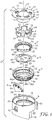
- a dose counter 2 of the present invention includes a lid 3, an indexer 4, a units teeth ring 5, a compression spring 6, a units rotational ring 7, a tens cone 8 and a housing 9. Those components are assembled as illustrated in FIGS. 2 , 3 and 7 .
- FIG. 1 represents an exploded view of a dose counter 2 of the present invention.
- the dose counter 2 comprises a units counter subassembly which counts individual doses in ones units as they are dispensed.
- the units counter subassembly includes all components shown except the tens cone 8.
- Alternative embodiments of the inventive dose counter 2 comprise additional counter components to count changes in tens units (and in some cases, changes in hundreds units) during the medication dosage counting process, as explained herein.
- the lid 3 has an open cylindrical part 11 with a wide rim 12 at a top end thereof.
- the cylindrical part 11 has its axis aligned coaxially with an axis 13.
- a plurality (e.g., five) of equally spaced slots 14 extend through the rim 12, and each of the slots 14 has a curved portion disposed in an annular manner, coaxially with respect to the axis 13.
- Each slot 14 has a central slot projection 15 that extends radially outwardly from the curved portion of the slot 14.
- a plurality (e.g., five) of ratchet members or teeth 16 project downwardly from a bottom surface of the rim 12, and are spaced circumferentially equally about the rim 12 relative to the axis 13.
- the lid 3 has a plurality (e.g., five) of lugs 17 of trapezoidal cross-section on its outer rim 18, and the lugs 17 are formed to engage complementary slots on a top rim of the housing 9, as explained herein.
- the indexer 4 is shaped like a castellated ring 20 that is coaxial with the axis 13.
- the ring has a plurality (e.g., five) of castellations 22 projecting upwardly therefrom.
- the castellations 22 are curved, like the curved portions of the slots 14.
- a protrusion 26 extends radially outward adjacent a top of each castellation 22, such that the lateral cross-section (relative to axis 13) of the top of each protrusion 26 and its respective castellation 22 corresponds closely to the shape of each of the curved slots 14 and each slot's respective central part 15. Accordingly, the castellations 22 can fit slidably through the slots 14 in the lid 12, in an axial direction.
- a units teeth ring 5 is also coaxial with axis 13, and is provided with two rings of upstanding teeth.
- An outer ring of teeth 30 is disposed for engagement with ratchet members 16 on the bottom surface of the rim 12 of the lid 3.
- An inner ring of teeth 32 is arranged for engagement with the sawtooth protrusions 24 on the indexer 4.
- Units teeth ring 5 has an outer circumferential surface 34 that has a plurality (e.g., four) of axially aligned grooves 36 disposed therein.
- WO 2005/060535 A2 The interaction of the lid 3, indexer 4 and units teeth ring 5 is functionally similar to that disclosed in WO 2005/060535 A2 , for causing the units teeth ring 5 to rotate about the axis 13 (i.e., to rotate the ring 5 an indexed amount as each dose of medication is dispensed).
- count indicia were provided on an outer circumferential surface of the counter ring bearing the two rings of upstanding teeth. In the present case, however, no indicia are borne by the units teeth ring 5 itself.
- WO 2005/060535 A2 is hereby incorporated by reference herein.
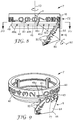
- the units rotational ring 7 is generally in the form of a hollow cylinder 38 that is coaxial with the axis 13.
- a plurality (e.g., four) of axially aligned ribs 40 extend radially inwardly from an internal surface 42 of the cylinder 38, terminating at a beveled ring 44 formed at the bottom of the cylinder 38.
- the units rotational ring 7 On an outer surface 46 of the cylinder 38, the units rotational ring 7 has a circumferential rim 48 extended thereabout adjacent the bottom of the cylinder 38.
- the circumferential rim 48 has a first set of missing arcuate segments or slots 48a, 48b, 48c, 48d and 48e, as seen in FIG. 1 (a second set of five missing arcuate segments or slots (not shown) are disposed 180 degrees around the other side of the units rotational ring 7 from the first set).
- the units rotational ring 7 has, on its outer circumferential surface 46, indicia for indicating ones units dosage counts of medication being dispensed.
- the indicia may take the form of digits from 9 to 0 arranged equally spaced twice about the circumference of the outer surface 46 of the cylinder 38.
- the digits are oriented so that they can be underlined by lines parallel to the axis 13, and the digits are arranged in two sequences of descending order in a clockwise direction when viewed from the bottom of the units rotational ring 7 (i.e., in the sequence: 9 8 7 6 5 4 3 2 1 0 9 8 7 6 5 4 3 2 1 0).
- the units rotational ring 7 has an oblong lug 50 spaced below and between each space between a 0 digit and its adjacent 9 digit. Since the digits 9 to 0 are arranged twice around the units rotational ring 7, there are two oblong lugs 50 thereon (on opposite sides of the ring 7).
- the ribs 40 on the units rotational ring 7 are disposed to align with the grooves 36 on the units teeth ring 5.
- the outer circumferential surface 34 of the units teeth ring 5 is slightly smaller in diameter than the internal surface 42 of the cylinder 38, thus allowing axial movement of the units teeth ring 5 relative to the units rotational ring 7.
- the interactions of the ribs 40 and respective grooves 36 couple the units teeth ring 5 and units rotational ring 7 for rotational purposes relative to the axis 13.
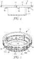
- the compression spring 6 is, in one embodiment, in the form of an annular leaf spring 52.
- the leaf spring 52 may be formed from a sheet of spring metal, although it may instead be formed of a suitable polymer material.
- the leaf spring 52 has a plurality (e.g., four) of cutouts 54 extending radially inwardly from an outer edge 56 thereof. Each of the cutouts 54 is formed and aligned to axially receive one of the ribs 40 of the units rotational ring 7 therein, thereby allowing axial movement of the compression spring 6 relative to the units rotational ring 7.
- the leaf spring 52 has an annular ring 58 with a plurality (e.g., four) of axially extending spring elements or leafs 60 thereon.
- each leaf 60 is biased downwardly from the ring 58 for engagement with the top of the beveled ring 44 within the cylinder 38 of the units rotational ring 7.
- the outer end of each leaf 60 is curved or otherwise formed to facilitate smooth sliding of the outer end with respect to the beveled ring 44.
- a top surface of the ring 58 of the leaf spring 52 engages a bottom surface of the units teeth ring 5. The leaf spring 52 thus urges the units teeth ring 5 axially away from the beveled ring 44 of the units rotational ring 7 and toward the sawtooth projections 24 on the indexer 4 and the ratchet members 16 on the bottom surface of the rim 12 of the lid 3.
- the leaf spring 52 may alternatively be assembled the other way up, so that the spring elements 60 are biased upwardly from the ring 58 for engagement with the bottom surface of the units teeth ring 5, while the other side of the leaf spring engages the top of the beveled ring 44.
- This alternative assembly may also be applied to other embodiments of the invention.
- any suitable keyed feature between units teeth ring 5 and units rotational ring 7 will suffice to couple those two components together for rotation, yet allow relative axial movement.
- rotation of the compression spring 6 relative to the units teeth ring 5 or units rotational ring 7 is permitted.
- any suitable keyed feature to accomplish that end will suffice.
- the housing 9 has a generally cylindrical body 62, with two forward wings 64 projecting outwardly therefrom and two forward legs 66 extending downwardly therefrom (only one of which is shown in FIG. 1 ).
- the cylindrical body 62 and the wings 64 and the legs 66 are formed to mate with interior surfaces of an actuator housing 68 for an aerosol container 70 (see FIG. 3 ).
- a count viewing window 72 is provided in the cylindrical body 62.
- a ledge 76 is disposed for alignment with the units rotational ring 7, as seen in FIG. 3 .
- the cylindrical body 62 has a top rim with a plurality (e.g., five) of slots 78 shaped for reception of the projections 17 on the lid 3 to provide a snap fit connection of the lid 3 and housing 9, or those components may be press fit together, or may be ultrasonically or otherwise (e.g., laser) welded together.
- a plurality e.g., five
- slots 78 shaped for reception of the projections 17 on the lid 3 to provide a snap fit connection of the lid 3 and housing 9, or those components may be press fit together, or may be ultrasonically or otherwise (e.g., laser) welded together.
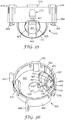
- the housing 9 has a lower rear internal cone-shaped recess 80 designed to accommodate the tens cone 8 therein, as best seen in FIGS. 3 and 6 .
- the tens cone 8 can thus rotate in a stable manner about an axis directed diagonally forward and upward from a rear corner 82 of the recess 80.
- the tens cone 8 protrudes partly from the housing 9, and is in part supported to rotate about an axis directed diagonally forward and upward from an inside of the actuator housing that receives the aerosol container.
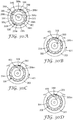
- the tens cone 8 has numbers from 12 to 0 arranged descending clockwise about an external conical surface 84 of the tens cone 8 when viewed from its pointed end 86.
- the orientation of the numbers is such that they can be underlined by slanted lines from the apex of the conical surface 84 (e.g., in the sequence: 12 11 10 9 8 7 6 5 4 3 2 1 0).
- An internal surface 87 of the tens cone 8 has a raised frustum 88 pointing the opposite way from the conical surface 84, as can be seen in FIG. 7 .
- annular series of equally spaced pegs 90 extend parallel to and in the same direction as the frustum 88 (parallel to an axis 92 of rotation for the tens cone 8, as seen in FIG. 8 ).
- the cylindrical part 11 of the lid 3 has a lower arcuate shelf 11a that extends over the top of the cone shaped recess 80 of the housing 9 to inhibit the ingress of dust, fibers, fluff or other debris from going therein.
- the dose counter 2 may be assembled by inserting the tens cone 8 into the housing 9, with the pointed end 86 of the conical surface 84 of the tens cone 8 seated in the rear corner 82 of the recess 80 in the housing 9.
- the circumferential rim 48 of the units rotational ring 7 has three slots 48c, 48d and 48e therein that correspond to positions of three of the pegs 90 on the tens cone 8, such that by correct orientation of the ring 7 and cone 8, the units rotational ring 7 can be seated on the ledge 76 of the housing 9, with three of the pegs 90 traversing the circumferential rim 48.
- the spring 6, units teeth ring 5, and indexer 4 can then be assembled in order over the units rotational ring 7, and the lid 3 fitted over the castellations 22 of the indexer 4 and then engaged with the housing 9.
- This complete assembly thus defines the dose counter 2, as seen in FIG. 2 .
- the internal working components of the dose counter 2 are fairly well enclosed by the housing 9 and lid 3, thus inhibiting the ingress of dust, fibers, fluff and other debris therein to protect those working components.
- the enclosure of the working components of the dose counter 2 (with the lid 3 engaged to the housing 9) also provides an assembly that is somewhat tamper resistant, and is durable and shock-resistant.
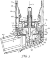
- FIG. 3 shows a vertical cross-sectional view through part of a press-and-breathe aerosol inhaler incorporating the dose counter 2 of FIGS. 1 and 2 .
- the purpose of the dose counter is to provide a display that indicates the number of doses of medication remaining or (in an alternative embodiment, not shown) the number already dispensed.
- the indicia provided for review by a user may be suitable alphabetic, numeric, alphanumeric, or color symbols, or any combination thereof, providing a sequential count up or count down of dispensed doses, or providing a more general indication such as "full" or "empty".
- the indicia would be visible through a window 94 in a side wall 96 of the actuator housing 68; alternatively, the side wall 96 may be transparent or have at least a portion thereof made of a transparent material to provide a viewing area or lens for viewing the indicia and count.
- the press-and-breathe inhaler comprises the actuator housing 68 having a cylindrical body 98 to accommodate the aerosol container 70.
- the actuator housing 68 has a mouthpiece 100.
- a nozzle block 102 is positioned within the actuator housing 68 and has an aperture to accommodate a valve stem 104 of the aerosol container 70 and a spray orifice 106.
- a metering valve 108 of the aerosol container 70 comprises a valve ferrule 110, valve stem 104, metering chamber 112 and return spring 114. As illustrated in FIG. 3 , the aerosol container 70 is also aligned coaxially with the axis 13.
- the housing 9 is designed to minimize interference and obstruction of the medication spray and airflow paths in the actuator housing 68.
- the dose counter 2 is clipped or retained within the actuator housing 68 by suitable detents or other engaging structure (not shown) between the actuator housing 68 and the dose counter 2.
- the dose counter 2 is designed to be useable with a variety of metering valve designs, and to fit compactly within commercially available actuator housing profiles so that it is not necessary to change the external configuration of those actuator housings to accommodate the inventive dose counter 2 therein.
- the FIGS. illustrate the dose counter 2 of the present invention in combination with an actuator housing for an inhaler of the type used for dispensing medication from a pressurized aerosol container (a pressurized metered dose inhaler or pMDI).
- inhalers in other forms may be used with the present invention including, for example, dry powder inhalers, portable nebulizers, and other metered dose dispensers that use reciprocal mechanism.
- the inhaler is actuated to dispense a dosage of medication by pressing down on the aerosol container 70 relative to the actuator housing 68.
- downward movement of the aerosol container 70 causes the valve ferrule 110 to engage top surfaces 22a of the castellations 22 of the indexer 4.
- the lid 3 is positioned low enough relative to the valve ferrule 110 so that those components never engage each other, thus ensuring sufficient space to allow adequate metering valve travel to guarantee the dispensing of a dose of medication.
- Engagement with the valve ferrule 100 causes the indexer 4 to move downwardly relative to the lid 3, and the sawtooth protrusions 24 of the indexer 4 engage teeth of the inner ring of teeth 32 of the units teeth ring 5.
- the dose counter 2 is designed to count at (or close before) the firing point of the metering valve 108 on the aerosol container 70, and then "lose” any subsequent excessive axial travel (i.e., lost "motion") of the axially moving components of the dose counter 2.
- the units rotational ring 7 is indexed to move rotationally one count increment, which will change the ones units count visible via the windows 72 and 94.
- the tens cone 8 is rotated as a function of the rotation of the units rotational ring 7 to move the number bearing portion of the conical surface 84 past the window 72.
- the axes 13 and 92 of the units rotational ring 7 and tens cone 8 are, as shown in FIG. 8 , disposed at an obtuse angle ⁇ relative to each other (i.e., disposed at an angle greater than 90 degrees and less than 180 degrees relative to each other).
- the angle ⁇ ranges from 110 degrees to 160 degrees.
- the angle ⁇ ranges from 125 degrees to 145 degrees.
- the angle ⁇ is 135 degrees.
- the axes 13 and 92 are coplanar, but not coaxial, parallel or perpendicular relative to each other.
- portions of the tens cone 8 and units rotational ring 7 converge adjacent the viewing window 72 of the housing 9.
- a circumferential segment of the outer surface 46 of the units rotational ring 7 that bears ones units indicia and an arcuate segment of the conical surface 84 that bears tens units indicia are aligned to collectively present at least a portion of a medication dosage count (for example, in FIG. 2 , the count "120" is seen, and in FIG. 9 , the count "129" is seen).
- the viewing window 72 provides a common view area for observing the indicia on the two separate indicia bearing surfaces.
- the viewing window 72 is aligned with the viewing window 94 in the side wall 96 of the actuator housing 68, thus presenting the common viewing area for observation by a user.
- the common viewing area is generally tangential to a circumferential surface of a cylinder disposed about the axis 13 (see FIG, 8 ).
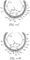
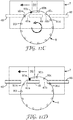
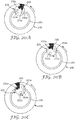
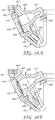
- Every tenth movement of the units rotational ring 7 results in a movement of the tens cone 8 due to interaction between one of the oblong lugs 50 (on the units rotational ring 7) and one of the pegs 90 (on the tens cone 8).
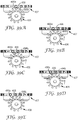
- the relationship between the lugs 50 and pegs 90 is illustrated schematically in FIGS. 10A-10D and FIGS. 11A-11D .
- This direct interaction between the units rotational ring 7 and the tens cone 8 eliminates the need for any transfer gear or other motion translation components between a component bearing ones units indicia (i.e., the units rotational ring 7) and a component bearing tens units indicia (i.e., the tens cone 8).
- This arrangement requires fewer parts, is more economical in function and is more compact.
- the use of fewer components in a dose counter reduces the number of components that must be manufactured within certain tolerance ranges, and thus reduces the possibility of component incompatibility or inoperabilities due to tolerance stack-up.
- the interaction in sequence for causing the tens cone 8 to change the indicia displayed in viewing window 72 involves engagement of one of the lugs 50 on the units rotational ring 7 with one of the pegs 90 on the tens cone 8.
- FIG. 10A as the units rotational ring 7 rotates clockwise, one of the lugs 50 thereon eventually moves into engagement with the peg 90a on the tens cone 8.
- FIG. 11A illustrates the relationship of the lug 50 and peg 90a at the time of their initial engagement caused by rotation of the units rotational ring 7 relative to the tens cone 8.
- the lug 50 pushes the peg 90a so far that rotation of the tens cone 8 moves the peg 90a out of the path of the advancing lug 50 (i.e., below the lug 50 as seen in FIG. 11D ).
- rotation of the tens cone 8 moves the peg 90a out of the path of the advancing lug 50 (i.e., below the lug 50 as seen in FIG. 11D ).
- further counterclockwise rotational movement of the tens cone 8 stops, and a new tens units number is aligned for observation through the viewing window 72.
- the new tens units number displayed will be a number smaller than the previous number that was displayed.
- Rotation of the tens cone 8 relative to the rotation of the units rotational ring 7 occurs each time one of the lugs 50 engages one of the pegs 90.
- the rotation of the tens cone 8 as a function of rotation of the units rotational ring 7 may be made more frequent or less frequent by providing more or less lugs 50 on the units rotational ring 7.
- the conical surface 84 of the tens cone 8 has thirteen tens units number bearing arcuate segments, and on its internal surface 87 the tens cone 8 correspondingly has thirteen pegs 90. If more or fewer number segments are desired to be provided on the tens cone 8, the number of pegs 90 must therefore accordingly be adjusted in a likewise fashion.
- the pegs on the tens cone 8 are referenced as pegs 90a, 90b, 90c, etc.
- the outer surface 46 of the units rotational ring 7 has the circumferential rim 48 thereon, which has slots 48a and 48b aligned adjacent each lug 50 to allow movement of pegs 90, as can be seen in the sequential illustrations of FIGS. 10 and 11 .
- peg 90a is moved by lug 50
- peg 90c moves through slot 48b in circumferential ring 48 (from below the slot 48b as seen in FIG. 11A to above the slot 48b as seen in FIG. 11D ).
- peg 90m moves through slot 48a as the tens cone 8 is rotated (from above the circumferential rim 48 as seen in FIG. 11A to below the circumferential rim 48 as seen in FIG. 11D ).
- the circumferential rim 48 acts to prevent rotation of the tens cone 8 except when one of the lugs 50 engages one of the pegs 90.
- tens cone 8 is constrained from movement about its axis by the circumferential rim 48 extending between the pegs 90m and 901. While movement of the tens cone 8 is allowed when the units rotational ring 7 and tens cone 8 are aligned as seen in FIGS. 10B and 10C (and in FIGS 11B and 11C ), the tens cone 8 is again prevented from movement once in the configuration shown in FIG. 11D . In the position shown in FIG.
- the circumferential rim 48 extends between the pegs 90a and 90d, and with further rotation of the units rotational ring 7, the circumferential rim 48 will extend between adjacent pegs 90a and 90m, and between adjacent pegs 90c and 90d.
- the tens cone 8 has been moved by interaction with one of the lugs 50 on the units rotational ring 7, it cannot rotate again until another lug 50 presents itself for engagement with the peg 90b on the tens cone 8, even though the units rotational ring 7 is rotating about its axis 13 to display differing ones units digits.
- cooperative features are provided between the housing 9 and tens cone 8 that will, when the tens cone 8 has been rotated to a position that shows a tens units 0 numeral in the view window 72, prevent further rotation of the tens cone 8.
- the units rotational ring 7 can continue to rotate as it counts down its nine remaining ones units counts, and then it would be prevented from further rotation by the tens cone 8.
- the viewing window would display a zero count for the dose counter 2.
- the aerosol dispensing assembly could be designed to cease dispensing doses of medication once the zero count has been reached, for example by limiting the free movement of the indexer 4.
- the inventive dose counter in the embodiment illustrated in FIGS. 1-11 operates in the following fashion.
- the valve ferrule 110 engages the indexer 4 to push it downwardly.
- Indexer 4 engages and then causes rotation of units teeth ring 5.
- the units rotational ring 7 is coupled rotationally to the units teeth ring 5, so it rotates as well.
- the indexer 4 and units teeth ring 5 also reciprocate down and up relative to the units rotational ring 7.
- a maximum dosage count of "129" medication dosages is shown. This allows for some testing of the aerosol dispensing assembly (e.g., 9 initial "tester” counts available), with 120 user available dispensing counts remaining. As noted above, changing the frequency or spacing of indicia on the units rotational ring and/or tens cone (along with corresponding changes in the interactive geometry between those components) allows modification of the possible count indicia shown.
- the indicia on the units rotational ring 7 would be disposed in the following order about its circumference: 9*8*7*6*5*4*3*2*1*0* (or with "1 ⁇ 2" in place of each asterisk) rather than the 9 8 7 6 5 4 3 2 1 0 9 8 7 6 5 4 3 2 1 0 indicia pattern described above.
- the tens cone 8 would then be moved after every twenty actuations (ten dosages) of the units rotational ring 7, rather than after every ten actuations thereof. This would allow the inventive dosage counter to achieve 240 actuation events, rather than have it limited to 120.
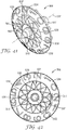
- FIGS. 12-20 illustrate a dose counter 202 of the present invention which provides a user with a possible dosage count ranging from 0 to 299.
- the dose counter 202 is similar to the dose counter 2 of FIGS. 1-11 , but includes a modified tens cone 208, a modified housing 209 and a hundreds disk 225.
- the other components of the dose counter 202 are essentially the same as those set forth for dose counter 2. For instance, the lid 3, indexer 4, units teeth ring 5, compression spring 6 and units rotational ring 7 are essentially the same, and operate the same as previously described.
- the interaction of the lid 3, indexer 4 and units teeth ring 5 is functionally similar to that disclosed in WO 2005/060535 A2 , for causing the units teeth ring 5 to rotate about the axis 13 (i.e., to rotate the ring 5 an indexed amount as each dose of medication is dispensed).
- the interaction between the units rotational ring 7 and tens cone 208 is also similar in terms of causing rotation of the tens cone 208 about its axis as a function of rotation of the units rotational ring 7.
- the tens cone 208 has numbers 9 to 0 arranged descending clockwise about external conical surface 284 of the tens cone 208 when viewed from a pointed end 286 thereof (i.e., in the sequence 9 8 7 6 5 4 3 2 1 0).
- the orientation for readability of the numbers is similar to the orientation on the tens cone 8.
- the conical surface 284 does not extend to the pointed end 286.
- the tens cone conical surface 284 extends only in a band adjacent an outer circumferential edge of the tens cone 208.
- An annual recess 284a is concentrically disposed within the band, and a small cone 284b protrudes concentrically within that recess 284a, capped by the pointed end 286. Also protruding within the recess 284a is a circumferential rim 285 surrounding the cone 284b.
- the rim 285 has a single gap 285a therein, and the recess 284a also has a ramp 289 projecting outwardly therefrom, which extends generally radially and outwardly from the gap 285a.
- An internal surface 287 of the tens cone 208 has a raised frustum 288 pointing the opposite way from the conical surface 284 as can be seen in FIG. 18 .
- an annular series of equally spaced pegs 290 extend parallel to and in the same direction as the frustum 288 (generally parallel to an axis 292 of rotation for the tens cone 208, as seen in FIG. 19 ). Since there are only ten numbers on the external surface 284 of the tens cone 208, there are only ten corresponding pegs 290 on the internal surface 287 thereof.
- the housing 209 again has a generally cylindrical body 262, with two forward wings 264 projecting outwardly therefrom and two legs 266 extending downwardly therefrom.
- the cylindrical body 262 and the wings 264 and the legs 266 are formed to mate with interior surfaces of the actuator housing 68 for the aerosol container 70 (see FIG. 16 ).
- a count viewing window 272 is provided in the cylindrical body 262.
- a ledge 276 is disposed for alignment with the units rotational ring 7, as seen in FIG. 16 .
- the cylindrical body 262 has a top rim with a plurality (e.g., five) of slots 278 shaped for reception of the projections 17 on the lid 3 to provide a snap fit connection of the lid 3 and housing 209 or those components may be press fit together, or maybe ultrasonically or otherwise (e.g., laser) welded together.
- a plurality e.g., five
- slots 278 shaped for reception of the projections 17 on the lid 3 to provide a snap fit connection of the lid 3 and housing 209 or those components may be press fit together, or maybe ultrasonically or otherwise (e.g., laser) welded together.
- the housing 209 has a lower rear internal cone shaped recess 280 designed to accommodate the tens cone 208 therein, as best seen in FIGS. 16 and 18 .
- the tens cone 208 can thus rotate in a stable manner about an axis directed diagonally forward and upward from a rear corner 282 of the recess 280.
- the housing 209 also has a generally vertically aligned arcuate slot 279 adjacent the recess 280 for reception and partial rotatable support of the hundreds disk 225.
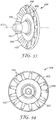
- the hundreds disk 225 has an external indicia bearing surface 227 extending generally perpendicular to a rotational axis 229 thereof (see, e.g., FIG. 19 ).
- the external surface 227 has numbers from 2 to 0 arranged descending clockwise thereon. The orientation of the numbers is generally adjacent and tangential to a circumferential edge of the circular external surface 227, with each number bisected horizontally by a radial line extending outwardly from the axis 229.
- An internal surface 231 of the hundreds disk 225 has three annularly equally spaced pegs 233 projecting outwardly therefrom, in a direction generally parallel to the axis 229 (see FIG. 17 ). Higher counts are possible by incorporating more numbers on a larger hundreds disc and correspondingly more pegs to match. When assembled, the internal surface 231 of the hundreds disk 225 faces and engages portions of the external surface 284 of the tens cone 208.
- the dose counter 202 may be assembled by inserting the hundreds disk 225 into the slot 279 of the housing 209.
- the tens cone 208 is then inserted into the housing 209, with the pointed end 286 of the small cone 284b thereon seated in the rear corner 282 of the recess 280 in the housing 209.
- the hundreds units number "2" of the hundreds disk 225 is aligned for observation through the viewing window 272
- the tens units number "0" on the tens cone 208 is aligned for observation through the viewing window 272.
- the circumferential rim 48 of the units rotational ring again has three slots 48c, 48d and 48e (such as shown in FIG.
- the units rotational ring 7 can be seated on the ledge 276 of the housing 209, with three of the pegs 290 traversing the circumferential rim 48.
- the ones units number "9" on the units rotational ring 7 is aligned for observation through the viewing window 272.
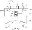
- the spring 6, units teeth ring 5, and indexer 4 can then be assembled in order over the units rotational ring 7, and the lid 3 fitted over the castellations 22 of the indexer 4 and then engaged with the housing 209. This complete assembly thus defines the dose counter 202 as seen in FIG. 15 .
- the internal working components of the dose counter 202 are fairly well enclosed by the housing 9 and lid 3, thus inhibiting the ingress of dust, fibers, fluff and other debris therein to protect those working components.
- the enclosure of the working components of the dose counter 202 (with the lid 3 engaged to the housing 9) also provides an assembly that is somewhat tamper resistant, and is durable and shock-resistant.
- a maximum dosage count of "299" medication dosages is shown. This allows for some testing or the aerosol dispensing assembly (e.g., 9 initial "tester” counts available), with 200 user available dispensing counts remaining. Changing the frequency or spacing of indicia on the units rotational ring, tens cone and/or hundreds disk (along with corresponding changes in the interactive geometry between those components) allows modification of the possible count indicia shown.
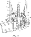
- FIG. 16 shows a vertical cross-sectional view through part of a press-and-breathe aerosol inhaler incorporating the dose counter 202 of FIGS. 12 , 15 and 18 .
- the purpose of the dose counter is to provide a display that indicates the number of doses of medication remaining or (in an alternative embodiment, not shown) the number already dispensed.
- the indicia provided for review by a user may be a suitable alphabetic, numeric, alphanumeric or color symbols, or any combination thereof, providing a sequential count up or count down of dispensed doses, or providing a more general indication, such as "full" or "empty”.
- the indicia would be visible through a window 94 in a side wall 96 of the actuator housing 68; alternatively, the side wall 96 may be transparent or have at least a portion thereof made of a transparent material to provide a viewing area or lens for viewing the indicia and count.
- the press-and-breathe inhaler is of the same structure and components as illustrated in FIG. 3 , and likewise cooperates with the dose counter 202 in the same manner to initiate a single ones units dosage count, as well as a change of decades (i.e., tens units) for counting by cooperation of the units rotational ring 7 and the tens cone 208.
- the aerosol container 70 is aligned coaxially with the axis 13.
- the housing 9 is designed to minimize interference and obstruction of the medication spray and airflow paths in the actuator housing 68.
- the dose counter 202 is clipped or retained within the actuator housing 68 by suitable detents or other engaging structure (not shown) between the actuator housing 68 and the dose counter 202.
- the dose counter 202 is designed to be useable with a variety of metering valve designs, and to fit compactly within commercially available actuator housing profiles so that it is not necessary to change the external configuration of those actuator housings to accommodate the inventive dose counter 202 therein.
- the FIGS. illustrate the dose counter 202 of the present invention in combination with an actuator housing for an inhaler of the type used for dispensing medication from a pressurized aerosol container.
- inhalers in other forms may be used with the present invention including, for example, dry powder inhalers, portable nebulizers, and other dispensers that use reciprocal mechanism.
- portions of the hundreds disk 225, the tens cone 208 and the units rotational ring 7 converge adjacent the viewing window 272 of the housing 209.
- a circumferential segment of the outer surface 46 of the units rotational ring 7 that bear ones units indicia, an arcuate segment of the conical surface 284 of the tens cone 208 that bears tens units indicia, and an arcuate segment of the external surface 227 of the hundreds disk 225 that bears hundreds units indicia are aligned to collectively present a medication dosage count (for example, in FIG. 14 , the count "100" is seen, and in FIG.
- the viewing window 272 provides a common view area for observing the indicia on the three separate indicia bearing surfaces.
- the external surface 227 of the hundreds disk 225 is thus generally parallel with the viewing area 272.
- the viewing window 272 is aligned with the viewing window 94 in the side wall 96 of the actuator housing 68, thus presenting the common viewing area for observation by a user.
- the common viewing area is generally tangential to a circumferential surface of a cylinder disposed about the axis 13.
- the rotational axis 229 of the hundreds disk 225 and the rotational axis 13 of the units rotational ring 7 are perpendicular to one another.
- the axis 229 of the hundreds disk 225 is disposed at an obtuse angle ⁇ with respect to the axis 92 of the tens cone 208.
- the angle ⁇ may assume the same ranges or value as stated above with respect to the angle ⁇ .
- the axes 13 and 292 are coplanar, but not coaxial, parallel or perpendicular relative to each other.
- the axes 292 and 229 are coplanar, but not coaxial, parallel or perpendicular relative to each other. In other embodiments of the invention, these pairs of axes need not be coplanar.
- Every tenth movement of the units rotational ring 7 results in a movement of the tens cone 208 due to interaction between one of the oblong lugs 50 (on the units rotational ring 7) and one of the pegs 290 (on the tens cone 208).
- the tens cone 208 thus rotates about its axis 292 as a function of the rotation of the units rotational ring 7 about its axis 13.
- the mechanics of the interaction between the tens cone 208 and the units rotational ring 7 are the same as illustrated in FIGS. 10 and 11 .
- the lug 50 on the units rotational ring 7 engages sequentially each peg 290 of the tens cone 208 to cause the tens cone 208 to rotate as function of rotation of the units rotational ring 7.
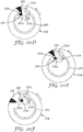
- Every complete rotation of the tens cone 208 results in a rotational movement of the hundreds disk 225 due to interaction between the ramp 289 (on the tens cone 208) and one of the pegs 233 (on the hundreds disk 225).
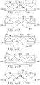
- the relationship between the ramp 289 and the pegs 233 is illustrated schematically in FIGS. 20A-20F .
- This direct interaction between the tens cone 208 and hundreds disk 225 eliminates the need for any transfer gear or other translation components between a component bearing tens units (i.e., the tens cone 208) and a component bearing hundreds units (i.e., the hundreds disk 225). This arrangement requires fewer parts, is more economical in function, and is more compact.
- the interaction and sequence for causing the hundreds disk 225 to change the hundreds units indicia displayed in the viewing window 272 involves engagement of the ramp 289 on the tens cone 208 with one of the pegs 233 on the hundreds disk 225.
- the tens cone 208 rotates counterclockwise, and the ramp 289 eventually moves into engagement with the peg 233a on the hundreds disk 225.
- the ramp 289 pushes the peg 233a (down and to the left, as viewed in FIG. 20B ) and thereby causes the hundreds disk 225 to rotate about its axis in a counterclockwise manner.
- FIG. 20A the tens cone 208 rotates counterclockwise, and the ramp 289 eventually moves into engagement with the peg 233a on the hundreds disk 225.
- the ramp 289 pushes the peg 233a (down and to the left, as viewed in FIG. 20B ) and thereby causes the hundreds disk 225 to rotate about its axis in a counterclockwise manner.
- the ramp 289 pushes the peg 233a so far down that rotation of the hundreds disk 225 moves the peg 233a out of the arcuate path of the advancing ramp 289 (i.e., out of reach of the ramp 289, as seen in FIG. 20E ).
- further counterclockwise rotational movement of the hundreds disk 225 stops, and a new hundreds units number is aligned for observation through the viewing window 272.
- the new hundreds units number displayed will be a smaller number than the previous number that was displayed.
- Rotation of the hundreds disk 225 relative to the rotation of the tens cone 208 occurs each time the ramp 289 engages one of the pegs 233.
- there is a single ramp 289 so for every single rotation of the tens cone 208, the hundreds disk 225 is rotated through one hundreds unit number (or, in the case where the hundreds disk 225 has three hundreds units thereon, the hundreds disk 225 is rotated 120°).
- the pegs on the hundreds disk 225 are referenced as pegs 233a, 233b and 233c.
- the external surface 284 of the tens cone 208 has an annular recess 284a thereon.
- the recess 284a is formed to accommodate the pegs 233.
- the circumferential rim 285 has a slot 285a aligned adjacent the ramp 289 and is provided to prevent movement of the pegs 233, as can be seen in the sequential illustrations of FIGS. 20A-20F .
- peg 233a moves through the slot 285a in the circumferential ring 285 (from below the slot 285a, as seen in FIG. 20A , to above the slot 285a, as seen in FIG. 20D ).
- peg 233a moves from above the slot 285a (see FIG. 20A ) to below the slot 285a (see FIG. 20E ).
- the circumferential rim 285 acts to prevent rotation of the hundreds disk 225 except when the ramp 289 engages one of the pegs 233.
- hundreds disk 225 is constrained from movement about its axis by the circumferential rim 285 extending between the peg 233c and the peg 233a (and the peg 233b). While movement of the hundreds disk 225 is allowed when the tens cone 208 and hundreds disk 225 are aligned as seen in FIGS. 20A-20E , the hundreds disk 225 is prevented from movement once in the configuration shown in FIG. 20F .
- the circumferential rim 285 extends between the opposed pegs 233c and 233a (or pegs 233c and 233b), and continued rotation of the tens cone 208 will maintain this relationship until the slot 285a of the circumferential rim 285 again reaches the position shown in FIG. 20A .
- the hundreds disk 225 has been moved by interaction with the ramp 289 on the tens cone 208, it cannot begin further rotation until the ramp 289 again presents itself for engagement with the peg 233c on the hundreds disk 225, even though the tens cone 208 is rotating about its axis to display differing tens units numbers.
- cooperative features are provided between the housing 9 and hundreds disk 225 that will, when the hundreds disk 225 has been rotated to a position that shows a hundreds units 0 numeral in the view window 272, prevent further rotation of the hundreds disk 225.
- the tens cone 208 can continue to rotate as it counts down its ten remaining tens units counts, and then it would be prevented from further rotation by the hundreds disk 225.
- the units rotational ring 7 can continue to rotate as it counts down its nine remaining ones units counts, and then it would be prevented from further rotation by the tens cone 208.
- the viewing window would display a zero count for the dose counter 202.
- the aerosol container may be dispensed by a user using the aerosol dispensing assembly, but the dose counter 202 will not register any further dosage counts.
- the aerosol dispensing assembly could be designed to cease dispensing doses of medication once the zero count has been reached, for example by limiting the free movement of the indexer 4.
- the inventive dose counter in the embodiment illustrated in FIGS. 12-20 operates in the following fashion.
- the valve ferrule 110 engages the indexer 4 to push it downwardly.
- Indexer 4 engages and then causes rotation of units teeth ring 5.
- the unit rotational ring 7 is coupled rotationally to the units teeth ring 5, so it rotates as well.
- the indexer 4 and units teeth ring 5 also reciprocate down and up relative to the units rotational ring 7.
- the tens cone 208 is indexed one position to change the tens unit count displayed thereon.
- Rotation of the tens cone 208 is translated into rotation of the hundreds disk 225 by engagement of the ramp 289 on the tens cone 208 with one of the pegs 233 on the hundreds disk 225.
- the hundreds disk 225 is only rotated periodically relative to the tens cone 208, to indicate a change in hundreds units of the counts (i.e., the hundreds disk 225 is only moved once for every ten movements of the tens cone 208).
- the hundreds disk 225 is indexed one position to change the hundreds units count displayed thereon.
- FIG. 21 illustrates a dose counter 302 of the present invention which provides a user with a possible dosage count ranging from 0 to 129.
- the dose counter 302 is similar to the dose counter 2 of FIGS. 1-11 , but each component thereof is modified. However, the dose counter 302 does include the same relative components, such as a lid 303, indexer 304, units teeth ring 305, compression spring 306, units rotational ring 307, tens cone 308 and housing 309. While the components differ in structure, they operate similarly to those described with respect to the dose counter 2 of FIGS. 1-11 . Actuation of the indexer 304 by a user causes indexed rotation of the units rotational ring 307, and the tens cone 308 is rotated as a function of rotation of the units rotational ring 307.
- the lid 303 is generally annular.
- a central circular hole 310 has a plurality (e.g., five) of circumferentially equally spaced radial hole extensions 311 of slightly greater radius thereon. Between adjacent hole extensions 311, the lid 303 has a plurality (e.g., five) of circumferentially equally spaced small radially inward protrusions 312 thereon. Adjacent an outer circumferential edge of the lid 303, a plurality (e.g., three) of circumferentially equally spaced cutaways 313 are defined by a radius slightly smaller than the outer edge.
- a cylindrical extension 314 extends downwardly from the lid 303, and has a smaller radius than the outer edge of the lid 303 (equal to the radius of the cutaways 313). Below each cutaway 313, the cylindrical extension 314 has an outward radial protrusion 315, shorter in circumferential length than the cutaways 313.
- the protrusions 315 are designed to form a snap fit with three doorframes 376 in the housing 309, as explained herein.
- the indexer 304 is shaped generally like a cylindrical cap with a central hole 316.
- the indexer 304 has a plurality (e.g., five) peripheral castellations 318 that are designed to pass through the hole extensions 311 of slightly greater radius in the central hole 310 of the lid 303.
- the indexer 304 also has a plurality (e.g., five) of peripheral grooves 320 extending from a top thereof to almost a bottom thereof, in directions parallel to an axis 322 of the indexer 304 and its associated lid 303 and designed to accommodate the protrusions 312 of the lid.
- a plurality e.g., five
- a plurality e.g., five
- the units teeth ring 305 is also coaxial with axis 322, and is provided with two rings of upstanding teeth.
- An outer ring of teeth 330 is disposed for engagement with ratchet members 331 on the bottom surface of the lid 303.
- An inner ring of teeth 332 is arranged for engagement with the sawtooth protrusions 326 on the indexer 304.
- a central cylinder 334 extends upwardly from the units teeth ring 305 to aid in keeping dust out of the dosage counter mechanism, and to serve as a guide for relative axial movement with the an inner cylinder 342 of the units rotational ring 307 (see FIG. 26 ).
- a circumferential perimeter of the units teeth ring 305 has a plurality (e.g., four) of circumferentially equally spaced features 336, with each feature 336 comprising a vertical recess with a pair of vertically oblong lugs on each side thereof.
- the interaction of the lid 303, indexer 304 and units teeth ring 305 is functionally similar to that disclosed in WO 2005/060535 A2 for causing units teeth ring 305 to rotate about the axis 322 (i.e., to rotate the ring 305 an indexed amount as each dose of medication is dispensed).
- the units rotational ring 307 is generally in the form of inner and outer coaxial cylinders 342 and 344, joined by an annular base 346. As seen in FIG. 26 , a circumferential rib 350 is disposed on a bottom side of the annular base 346. The rib 350 provides a low friction surface for the units rotational ring 307 to rotate relative to a shelf 381 of the housing 309 on which it rests. An upwardly extending circumferential groove 352 is also provided on a bottom surface of the annular base 346, coaxially within the rib 350, to accommodate a spindle 397 of the tens cone 308, at all rotational positions of the units rotational ring 307 with respect to the tens cone 308.
- the outer cylinder 344 has a further external cylindrical section 356 joined approximately midway up an outer surface of the outer cylinder 344 via an annular wall 358.
- An internal circumferential surface 360 of the outer cylinder 344 has a plurality (e.g., four) of features 362 (see FIG. 22 ).
- Each feature 362 comprises a pair of grooves on either side of a vertically oriented radially inwardly projecting rib.
- the features 362 are designed to slide in an axial orientation with the corresponding features 336 of the units teeth ring 305.
- the inner cylinder 342 of the units rotational ring 307 has a diameter such that it slides axially inside the central cylinder 334 of the units teeth ring 305. As seen in FIGS.
- an additional small cylindrical section 364 (of smaller diameter than the inner cylinder 342) extends from a lower end of the units rotational ring 307, and is designed to fit around the nozzle block 102 of the actuator housing 68.
- the external cylindrical section 356 has an outer cylindrical surface 366 bearing indicia for indicating ones units dosage counts of medication being dispensed. As illustrated by FIGS. 21 and 22 , the indicia may take the form of digits from 9 to 0 arranged equally spaced twice about the circumference of the outer surface 366 of the external cylindrical segment 356.
- the digits are oriented so that they can be underlined by lines parallel to the axis 322, and the digits are arranged in two sequences of descending order in a clockwise direction when viewed from the bottom of the units rotational ring 307 (i.e., in the sequence: 9 8 7 6 5 4 3 2 1 0 9 8 7 6 5 4 3 2 1 0).
- the units rotational ring 307 has an oblong lug 368 spaced below and between each space between a 0 digit and its adjacent 9 digit. Since the digits 9 to 0 are arranged twice around that units rotational ring 307, there are two oblong lugs 368 thereon (on opposite sides of the ring 307).
- the features 362 on the units rotational ring 307 are disposed to align with the features 336 on the units teeth ring 305.
- the outer circumferential edge of the units teeth ring 305 is slightly smaller in diameter than the internal surface 360 of the outer cylinder 344, thus allowing axial movement of the units teeth ring 305 relative to the units rotational ring 307.
- the interaction of the features 362 and 336 couple the units teeth ring 305 and units rotational ring 307 for rotational purposes relative to the axis 322.
- the compression spring 306 is similar to that disclosed in the embodiments above.
- it can be in the form an annular leaf spring 370.
- the leaf spring 370 has a plurality (e.g., three) of cutouts 372 extending radially inwardly from an outer circumferential edge thereof.
- Each of the cutouts 372 is formed and aligned to axially receive one of the features 362 of the units rotational ring 307 therein, thereby allowing axial movement of the compression spring 306 relative to the units rotational ring 307.
- the leaf spring 370 has an annular ring with a plurality (e.g., three) of axially extending spring elements or leafs 374 thereon.
- the spring elements 374 are biased downwardly from the leaf spring 370 for engagement with the top of the annular base 346 of the units rotational ring 307.
- the outer end of each leaf 374 is curved or otherwise formed to facilitate to smooth sliding of the outer end with respect to the annular base 346.
- a top surface of the ring of the leaf spring 370 engages a bottom surface of the units teeth ring 305. The leaf spring 370 thus urges the units teeth ring 305 axially away from the annular base 346 of the units rotational ring 307 and toward the sawtooth projections 326 on the indexer 304 and the ratchet members 331 on the bottom surface of the lid 303.
- any suitable keyed features between units teeth ring 305 and units rotational ring 307 will suffice to couple those two components together for rotation, yet allow relative axial movement.
- rotation of the compression spring 306 relative to the units teeth ring 305 or units rotational ring 307 is permitted.
- any suitable keyed feature to accomplish that end will suffice.
- the housing 309 has a generally cylindrical body 375 with a plurality (e.g., three) of doorframe features 376, two forward legs 378 and a viewing window 379 thereon.
- the housing 309 is also generally coaxial with respect to the axis 322, and has a lateral shelf 381 therein.
- the shelf 381 has a central hole 382 therethrough for accommodating the nozzle block 102 of the actuator housing 68, as seen in FIGS. 26 and 27 .
- the housing 309 On a rear side thereof (defined as including the viewing window 379), the housing 309 has a conical housing section 383 extending downwardly therefrom and designed to accommodate the tens cone 308 therein, as seen in FIGS. 24-28 .
- the tens cone 308 is aligned to rotate in a stable manner about an axis directed diagonally forward and upward from the rear of the housing 309.
- the relationship of the axis of the tens cone 308 relative to the axis 322 of the units rotational ring 307 in this embodiment is similar to that illustrated and stated for those components in FIGS. 8 and 19 of the first and second embodiments (i.e., for FIG. 8 , the axis 92 of tens cone 8 and the axis 13 of units rotational ring 7, and for the FIG. 19 , the axis 292 of the tens cone 208 and the axis 13 of the units rotational ring 7).
- the conical housing section 383 has a central hole 3 84 therethrough, and internally is shaped to support a conical wall of the tens cone 308 and to surround and engage splines thereon (as well as providing upper and lower axis passages for assembly and tooling).
- the conical housing section 383 has a gutter portion 385 (see FIG. 26 ) at its apex end where it adjoins the shelf 381 to support an upper part of a spindle of the tens cone 308.
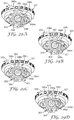
- the circular hole 384 has a projection 386 extending radially inwardly thereon (see FIGS. 30A-D ).
- the cylindrical wall 375 Adjacent a lower front end of the housing 309, the cylindrical wall 375 has a stepped portion 387 which partly conforms to an external surface of units rotational ring 307. This stepped portion 387 on the external profile of the housing 309 is shaped to minimize potential interference with medication spray emerging from the spray orifice 106 of the nozzle block 102 when the inhaler is actuated.
- Each doorframe feature 376 has an inverted U-shaped section defined by upwardly extending legs 390 and 391 and cross beam member 392 (see FIGS. 24 and 25 ).
- each protrusion 315 is aligned within one of the doorframe features 376.
- Each doorframe feature 376 flexes outwardly as the protrusion 315 passes by it during assembly, and then snaps back into place with the cross beam member 92 over the protrusion 315, thereby fixing the lid 303 to the housing 309.
- the lid 303 and housing 309 may be otherwise connected together, such as by press fit connections, or may be ultrasonically or otherwise (e.g., laser) welded together.
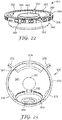
- the tens cone 308 has numbers from 12 to 0 arranged descending clockwise about an external conical surface 394 of the tens cone 308 when viewed from an apex of the conical surface 394 (e.g., in the sequence: 12 11 10 9 8 7 6 5 4 3 2 1 0).
- the orientation for readability of the numbers is similar to the orientation on the tens cone 8.
- the conical surface 394 extends only in a band adjacent an outer circumferential edge of the tens cone 308.
- An internal surface 395 of the tens cone 308 is also generally conical (inversely) and is provided with a plurality (e.g., thirteen) of radial spokes 396.
- a forward and upwardly directed spindle 397 extends from the center of the internal surface 395 of the tens cone 308.
- the tens cone 308 rotates about an axis 398, once assembled in the dose counter 302 (as seen in FIG. 26 ).
- the tens cone 308 On its external side, the tens cone 308 has a plurality (e.g., thirteen) of splines 399 arranged annularly about and parallel to the axis 398.
- the splines 399 project externally from the tens cone 308 in a generally cylindrical configuration to define a boss that is, upon assembly, received within the hole 384 of the conical housing section 383 in the housing 309.
- the splines 399 thus point in an opposite direction from the spindle 397 on the tens cone 308.
- Twelve of the splines 399 are identical in lateral cross section, having a cross section similar to that of a "fairy cake” or “cupcake” (see, e.g., splines 399a to 3991 in FIG. 30A ).
- a curved top portion or cap of each spline 399 is farthest from the axis 398 of the tens cone 308.
- the thirteenth spline 399m is, in part, similarly shaped, but has a base portion 400 extended axially inwardly toward the axis 398 of the tens cone 308.
- the splines 399a to 3991 are formed to be able to flex slightly radially inwardly relative to the axis 398, while the spline 399m is more rigid than the other splines 399a to 3991, and is not able to flex radially inwardly.
- the dose counter 302 may be assembled by inserting the tens cone 308 into the housing 309, with the spindle 397 of the tens cone 308 seated upon the gutter portion 385 in the conical housing section 383 of the housing 309.
- the boss formed by the splines 399 is also aligned to extend into the hole 384 of the conical housing section 383.
- the units rotational ring 307 is then inserted and seated on the shelf 381 of the housing 309, above the tens cone 308 (see FIG. 26 ). In this embodiment, the units rotational ring 307 completely covers the tens cone 308 in the conical housing section 383, to inhibit the ingress of dust, fibers, fluff or other debris from falling into the tens cone 308.
- the spring 306, units teeth ring 305 and indexer 304 can then be assembled in order over the units rotational ring 307, and the lid 303 fitted about the castellations 311 of the indexer 304.
- the lid 303 is snap-fit engaged with the housing 309 by engagement of the protrusions 315 and associated doorframe features 376.
- This complete assembly thus defines the dose counter 302 as seen in FIGS. 24, 25 , 26 and 27 .
- the internal working components of the dose counter 302 are fairly well enclosed by the housing 309 and lid 303, thus inhibiting the ingress of dust, fibers, fluff and other debris therein to protect those working components.
- the enclosure of the working components of the dose counter 302 (with the lid 303 engaged to the housing 309) also provides an assembly that is somewhat tamper resistant, and is durable and shock-resistant.
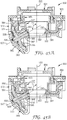
- FIG. 27 shows a vertical cross sectional view through part of a press-and - breath aerosol inhaler incorporating the dose counter 302 of FIGS. 21 , 24 , 25 , 26 and 28 .
- the purpose of the dose counter is to provide a display that indicates the number of doses of medication remaining, or (in an alternative embodiment, not shown) the number already dispensed.
- the indicia provided for review by a user may be suitable alphabetic, numeric, alphanumeric, or color symbols or any combination thereof, providing a sequential count up or count down of dispensed doses, or providing a more general indication, such as "full" or "empty".
- the indicia would be visible through a window 94 in a side wall 96 of the actuator housing 68; alternatively, the side wall 96 may be transparent or have at least a portion thereof made of a transparent material to provide a viewing area or lens for viewing the indicia and count.
- the press-and-breathe inhaler is of the same structure and components as illustrated in FIG. 3 , and likewise cooperates with the dose counter 302 in a similar manner to initiate a single ones units dosage count, as well as a change of decades (i.e., tens units) for counting by cooperation of the units rotational ring 307 and the tens cone 308. As illustrated in FIG. 27 , the aerosol container 70 is also aligned coaxially with the axis 322.
- the ferrule 110 engages a top surface of the indexer 304. It will be appreciated by those familiar with metering valves that the profiles of various kinds of valve ferrule differ, and that the indexer is suitably designed to abut a the ferrule flatly to minimize variations in travel between valves of the same kind due to tolerances on components.
- the inhaler is actuated to dispense a dosage of medication by pressing down on the aerosol container 70 relative to the actuator housing 68.
- downward movement of the aerosol container 70 causes the valve ferrule 110 to push down on the indexer 304.
- the lid 303 is positioned low enough relative to the valve ferrule 110 so that those components never engage each other, thus ensuring sufficient space to allow adequate metering valve travel to guarantee the dispensing of a dose of medication.
- Engagement with the valve ferrule 100 causes the indexer 304 to move downwardly relative to the lid 303, and the sawtooth protrusions 326 of the indexer 304 engage teeth of the inner ring of teeth 332 of the units teeth ring 305.
- the ring 305 rotates (as described in WO 2005/060535 A2 ). Such rotational movement results in coupled rotational movement of the units rotational ring 307.
- the compression spring 306 between the units rotational ring 307 and the units teeth ring 305 maintains relative engagement of the sawtooth protrusions 326 and inner ring of teeth 332 until the downward actuation force on the aerosol container 70 is removed, and the return spring 114 urges the valve ferrule 110 upwardly relative to the nozzle block 102.
- the dose counter 302 is designed to count at (or close before) the firing point of the metering valve 108 on the aerosol container 70, and then "lose” any subsequent excessive axial travel (i.e., lost "motion") of the axially moving components of the dose counter 302.
- the units rotational ring 307 is indexed to move rotationally one count increment, which will change the ones units count visible via the windows 379 and 94.
- the housing 309 is designed to minimize interference and obstruction of the medication spray and airflow paths in the actuator housing 68.
- the dose counter 302 is clipped or retained within the actuator housing 68 by suitable detents or other engaging structure (not shown) between the actuator housing 68 and the dose counter 302.
- the dose counter 302 is designed to be useable with a variety of metering valve designs, and to fit compactly within commercially available actuator housing profiles so that it is not necessary to change the external configuration of those actuator housings to accommodate the inventive dose counter 302 therein.
- the FIGS. illustrate the dose counter 302 of the present invention in combination with an actuator housing for an inhaler of the type used for dispensing medication from a pressurized aerosol container.
- inhalers in other forms may be used with the present invention including, for example, dry powder inhalers, portable nebulizers, and other dispensers that use reciprocal mechanism.
- portions of the tens cone 308 and units rotational ring 307 converge adjacent the viewing window 379 of the housing 309.
- a circumferential segment of the outer surface 366 of the units rotational ring 307 that bears ones units indicia and an arcuate segment of the conical surface 394 of the tens cone 308 are aligned to collectively present at least a portion of a medication dosage count (for example, in FIG. 24 , the count "129” is seen, and in FIG. 25 , the count "29" is seen).
- the viewing window 379 provides a common viewing area for viewing the indicia on the two separate indicia viewing surfaces.
- the viewing window 379 is aligned with the viewing window 94 in the side wall 96 of the actuator housing 68, thus presenting the common viewing area for observation by a user.
- the common viewing area is generally tangential to a circumferential surface of a cylinder disposed about the axis 322.
- Every tenth movement of the units rotational ring 307 results in a movement of the tens cone 308 due to interaction between one of the oblong lugs 368 (on the units rotational ring 307) and one of the spokes 396 (on the tens cone 308).
- the relationship between the lugs 368 and spokes 396 is illustrated schematically in FIGS. 29A-29D .
- This direct interaction between the units rotational ring 307 and the tens cone 308 eliminates the need for any transfer gear or other motion translation components between the component bearing ones units indicia (i.e., the units rotational ring 307) and the component bearing tens units indicia (i.e., the tens cone 308).
- This arrangement requires fewer parts, is more economical in function, and is more compact.
- the use of fewer components in a dose counter reduces the number of components that must be manufactured within certain tolerance ranges, and thus reduces the possibility of component incompatibility or inoperabilities due to tolerance stack up.
- the interaction and sequence for causing the tens cone 308 to change the indicia displayed in the viewing window 379 involves engagement of one of the lugs 368 on the units rotational ring 307 with one of the spokes 396 on the tens cone 308.
- FIG. 29A illustrates the relationship of the lug 368 and spoke 396a at the time of their initial engagement caused by rotation of the units rotational ring 307 relative to the tens cone 308.
- the lug 368 pushes the spoke 396a so far that rotation of the tens cone 308 moves the spoke 396a out of the path of the advancing lug 368 (i.e., below the lug 368 as seen in FIG. 29D ).
- further counter clockwise rotational movement of the tens cone 308 stops, and a new tens units number is aligned for observation through the viewing window 379.
- the new tens units number displayed will be a number smaller than the previous number that was displayed.
- Rotation of the tens cone 308 relative to the rotation of the units rotational ring 307 occurs each time one of the lugs 368 engages one of the spokes 396.
- there are two lugs 368 on the units rotational ring 307 so for every complete rotation of the units rotational ring 307 (which represents twenty ones units numbers) the tens cone 308 is rotated through two tens units numbers.
- the rotation of the tens cone 308 as a function of rotation of the units rotational ring 307 may be made more frequent or less frequent by providing more or fewer lugs 368 on the units rotational ring 307.
- the conical surface 394 of the tens cone 308 has thirteen tens units numbers bearing arcuate segments, and on its internal surface 395 the tens cone 308 correspondingly has thirteen spokes 396. If more or fewer arcuate number segments are desired to be provided on the tens cone 308, the number of spokes 396 must therefore accordingly be adjusted in a likewise fashion.
- the position of the tens cone 308 is maintained as it is indexed through each of its tens units numbers for display by the interaction of the splines 399 and the projection 386 on the housing 309, as illustrated in FIGS. 30A-30D .
- This arrangement also provides a mechanism for establishing a zero count for the dose counter 302, thus preventing further count down number changes when that zero dosage count is reached.
- the projection 386 is shaped to extend between adjacent splines 399 (such as between splines 399k and 3991).
- the sequence of movement shown in FIGS. 30A-30D corresponds generally in position to the sequential movement positions of the tens cone 308 in FIGS. 29A-29D . As seen in FIG.
- FIG. 30B illustrates continued movement of the tens cone 308 relative to the projection 386. Once the spline 3991 has moved past the projection 386, it snaps back to its original configuration as seen in FIG. 30D .
- the aerosol dispensing assembly could be designed to cease dispensing doses of medication once the zero count has been reached, for example by limiting the free movement of the indexer 304.
- the inventive dose counter 302 in the embodiment illustrated in FIGS. 21-30 operates in the following fashion.
- the valve ferrule 110 engages the indexer 304 to push it downwardly.
- Indexer 304 engages and then causes rotation of the units teeth ring 305.
- the units rotational ring 307 is coupled rotationally to the units teeth ring 305, so it rotates as well.
- the indexer 304 and units teeth ring 305 also reciprocate down and up relative to the units rotational ring 307.
- the ring 307 When complete down and up reciprocal movement of the units teeth ring 305 causes the units rotational ring 307 to rotate on its axis 322, the ring 307 has a single ones units count change in position thereof. Rotation of the units rotational ring 307 is translated into rotation of the tens cone 308 by engagement of the lug 368 on the units rotational ring 307 with one of the spokes 396 on the tens cone 308. However, the tens cone 308 is only rotated periodically relative to the units rotational ring 307, to indicate a change in decade of the counts (i.e., the tens cone 308 is only moved once for every ten movements of the units rotational ring 307). Each time the units rotational ring 307 counts ten ones units counts, the tens cone 308 is indexed one position to change the tens units count displayed thereon.
- a maximum dosage count of "129" medication dosages is shown. This allows for some testing of the aerosol dispensing assembly (e.g., nine initial "tester” counts available with 120 user available dispensing counts remaining). As noted above, changing the frequency or spacing of indicia on the units rotational ring and/or tens cone (along with corresponding changes in the interactive geometry between those components) allows modification of the possible count indicia shown.
- FIGS. 31-40 A fourth embodiment of the inventive dose counter is illustrated in FIGS. 31-40 .
- This embodiment is referenced as dose counter 402 (see FIGS. 37A and 37B ), and is generally similar to the third embodiment, except that the mechanism for preventing reverse movement of the counter components has been modified.
- the tens cone no longer has splines visible through a circular hole in a conical housing section of the housing. Instead, the tens cone has an annular sawtooth array disposed to engage a beveled protrusion on an inner movable face of the housing.
- FIGS. 31-34 illustrate a tens cone 408 of the fourth embodiment dose counter 402.
- the tens cone 408 has numbers 12 to 0 arranged descending clockwise about an external conical surface 484 of the tens cone 408 when viewed from an apex of the conical surface 484 (i.e., in the sequence 12 11 10 9 8 7 6 5 4 3 2 1 0).
- the orientation for readability of the numbers is similar to the orientation on the tens cone 8.
- the conical surface 484 extends only in a band adjacent an outer circumferential edge of the tens cone 408.
- the tens cone 408 Concentrically within the band, the tens cone 408 has an annular recess 435 sloped such that the recess 435 is deepest nearest an axis 437 of the tens cone 408.
- a short cylindrical wall 441 forms an inside wall of the recess 435.
- Radially within the cylindrical wall 441 is an annular sawtooth array 443 surrounding an axial hole 445.
- a narrow radial in-fill element 447 bridges the deepest part of the recess 435 between the external conical surface 484 and the cylindrical wall 441, at about the "6 o'clock" position, as indicated by the tens units digits on the external conical surface 484 (see FIG. 32 ).
- An internal surface 495 of the tens cone 408 is formed the same as the internal surface 395 of the tens cone 308, bearing radial spokes 496 and a spindle 497 thereon (see FIGS. 33 and 34 ).
- a housing 409 which again has a generally cylindrical body 462 with two forward legs 466 extending downwardly therefrom, and a viewing window 472 thereon.
- the housing 409 has a plurality (e.g., three) of doorframe features 476 thereon, shaped similarly and for the same function as the doorframe features 376 of housing 309 (to clip the housing 409 to a lid for the dose counter 402).
- the housing 409 also has a lateral shelf 481 therein, which has a central hole 482 therethrough for accommodating the nozzle block of the actuator housing.
- the housing 409 On a rear side thereof (defined as including the viewing window 472), the housing 409 has a conical housing section 483 extending downwardly therefrom and designed to accommodate the tens cone 408 therein, as seen in FIGS. 37A and 37B .
- the tens cone 408 is aligned to rotate in a stable manner about an axis directed diagonally forward and upward from the rear of the housing 409.
- the relationship of the axis 437 of the tens cone 408 relative to an axis 422 of the housing 409 in this embodiment is similar to that illustrated and stated for the those axes of the same components of the third embodiment (compare FIGS. 37A and 37B with FIG. 26 ).
- the conical housing section 483 is shaped internally to generally conform to the external side of the tens cone 408 except within the cylindrical wall 441 and recess 435 thereof.
- the conical housing section 483 has an inner planar face 454 that is flush with a top surface which corresponds to the cylindrical wall 441, except for a beveled protrusion 455 designed to fit between the teeth of the sawtooth array 443.
- That portion 457 of the conical housing section 483 that corresponds to the recess 435 of the tens cone 408 has a protruding ramp 459 directed axially inwards and designed to abut the in-fill element 447 when the tens cone 408 has rotated far enough to bring the ramp 459 and in-fill element 447 into engagement. This ultimately corresponds to the zero position for the counter elements of the dose counter 402.
- FIGS. 37A and 37B illustrate the tens cone 408, housing 409 and other components of the dose counter 402.
- Those other components conform generally to the configuration of like components in the embodiment illustrated in FIGS. 21-30 .
- a lid 403 corresponds to lid 303
- an indexer 404 corresponds to indexer 304
- a units teeth ring 405 corresponds to units teeth ring 305
- a compression spring 406 corresponds to compression ring 306
- a units rotational ring 407 corresponds to units rotational ring 307.
- the lid 403, indexer 404, units teeth ring 405, spring 406 and units rotational ring 407 are assembled with the tens cone 408 and housing 409 as illustrated in FIGS. 37A and 37B .
- This assembly is generally identical to that illustrated in the embodiment of FIGS. 21-30 .
- Indexing of the units rotational ring 407 is accomplished in the same manner in the embodiment of FIGS. 31-40 as in the embodiment of FIGS. 21-30 .
- indexing of the tens cone 408 is accomplished in the same manner in the embodiment of FIGS. 31-40 as in the embodiment of FIGS. 21-30 .
- the spokes 496 of the tens cone 408 are periodically engaged and advanced by a lug 468 on the units rotational ring 407, in the fashion illustrated schematically by FIGS. 29A-29D (and as illustrated for like structure in FIGS. 39A-39E ).
- An outer cylindrical surface 466 bears ones units indicia of the units rotational ring 407, and is viewable through the viewing window 472.
- the tens cone 408 bears tens units indicia on the external surface 484 thereof.
- the indicia on the surface 466 and the surface 484 are tangentially aligned within the viewing window 472, at the common viewing area, to present a representative dosage count to a user.
- the indicia bearing surfaces are aligned like those of like structure in the earlier described embodiments.
- the conical housing section 483 has a center pivoting section 461 which is separated from the conical housing section 483 along its side edges 463 and 465 and its top edge 467.
- This configuration thus allows the center pivoting section 461 to flex outwards slightly from a bottom portion 469 thereof connected to the conical housing section 483 to allow the beveled protrusion 455 to ride over the sawtooth array 443 when sufficient force is applied to cause rotation of the tens cone 408.
- FIGS. 40A-40E illustrate schematically and sequentially the interaction between the beveled protrusion 455 on the center pivoting section 461 of the conical housing section 483 of the housing 409.
- FIG. 40A shows the relationship between the beveled protrusion 455 and the teeth of the sawtooth array 443 when the tens cone 408 is fixed in place rotationally to display one of the tens units numbers thereon (such as aligned in FIGS. 37A and 38A ).
- a tooth 443a of the sawtooth array 443 moves to the left (as seen in FIG.
- the in-fill element 447 on the tens cone 408 is rotated into abutment with the ramp 459 on the housing 409. Following this point of abutment (when the units rotational ring is showing a 9 as its ones units digit), as the units rotational ring 408 completes its last ten ones units counts, the protruding oblong lug 468 can no longer move a radial spoke 496 on the tens cone 408. Thus, the units rotational ring 407 will also be unable to advance beyond 0 as its ones units digit, once the tens cone 408 has reached 0 as its tens units numeral, despite further actuations of the inhaler.
- the inventive dose counter 402 in the embodiment illustrated in FIGS. 31-40 operates in the following fashion.
- the valve ferrule engages the indexer 404 to push it downwardly.
- Indexer 404 engages and then causes rotation of the units teeth ring 405.
- the units rotational ring 407 is coupled rotationally to the units teeth ring 405, so it rotates as well.
- the indexer 404 and units teeth ring 405 also reciprocate down and up relative to the units rotational ring 407.
- the ring 407 When complete up and down reciprocal movement of the units teeth ring 405 causes the units rotational ring 407 to rotate on its axis 422, the ring 407 has a single ones units count change in position thereof. Rotation of the units rotational ring 407 is translated into rotation of the tens cone 408 by engagement of the lug 468 on the units rotational ring 407 with one of the spokes 496 on the tens cone 408. However, the tens cone 408 is only rotated periodically relative to the units rotational ring 407, to indicate a change in decade of the count (i.e., the tens cone 408 is only moved once for every ten movements of the units rotational ring 407). Each time the units rotational ring 407 counts ten ones units counts, the tens cone 408 is indexed one position to change the tens units counts displayed thereon.
- FIGS. 41-47 A fifth embodiment of the inventive dose counter is illustrated in FIGS. 41-47 .
- This embodiment is referenced as dose counter 502 (see FIGS. 45A and 45B ), and is generally similar to the third embodiment, except that the mechanism for preventing reverse movement of the counter components has been modified.
- the tens cone no longer has splines visible through a circular hole in a conical housing section of the housing. Instead, the tens column has an annular array of teardrop shaped recesses disposed to engage a teardrop shaped protrusion on an inner face of the housing.
- the tens cone of this embodiment and its associated housing and units rotational ring are configured to allow a rocking motion of the tens cone as it is rotated to engage and disengage one of its teardrop shaped recesses with the teardrop shaped protrusion on the housing.
- FIGS. 41-43 illustrate a tens cone 508 of the fifth embodiment dose counter 502.
- the tens cone has numbers 12 to 0 arranged descending clockwise about an external conical surface 584 of the tens cone 508 when viewed from an apex of the conical surface 584 (i.e., in the sequence 12 11 10 9 8 7 6 5 4 3 2 1 0).
- the orientation for readability of the numbers is similar to the orientation on the tens cone 8.
- the conical surface 584 extends only in a band adjacent an outer circumferential edge of the tens cone 508.
- the tens cone 508 Concentrically within the band, the tens cone 508 has an annular surface 535 which adjoins the conical surface 584 and extends perpendicular to an axis 537 of rotation for the tens cone 508. An annular array 537 of teardrop shaped recesses 539 are disposed on the annular surface 535. Each teardrop shaped recess 539 has its narrower end pointed radially outwardly from the axis 537 of the tens cone 508. Concentrically within the annular surface 535, the tens cone 508 has an annular recess 541 that is sloped such that the recess 541 is deepest nearest the axis 537 of the tens cone 508.
- the annular recess 541 abuts and surrounds a protruding boss 543 of the tens cone 508, with the boss 543 being coaxial with the axis 537.
- a narrow radial in-fill element 545 bridges the recess 541 between the annular surface 535 and the boss 543, at about the "6 o'clock" position, as indicated by the tens units digits on the external conical surface 584.
- An internal surface 595 of the tens cone 508 is formed the same as the internal surface 395 of the tens cone 308 (and the same as the internal surface 495 of the tens cone 408), bearing radial spokes 596 and a spindle 597 thereon (see FIG. 43 ).
- a housing 509 which again has a generally cylindrical body 562 with two forward legs 566 extending downwardly therefrom, and a viewing window 572 thereon.
- the housing 509 has a plurality (e.g., three) of doorframe features 576 thereon, shaped similarly and for the same function as the doorframe features 376 of housing 309 (to clip the housing 509 to a lid for the dose counter 502).
- the housing 509 also has a lateral shelf 581 therein, which has a central hole 582 therethrough for accommodating the nozzle block of the actuator housing.
- the housing 509 On a rear side thereof (defined as including the viewing window 572), the housing 509 has a conical housing section 583 extending downwardly therefrom and designed to accommodate the tens cone 508 therein, as seen in FIGS. 45A and 45B .
- the tens cone 508 is aligned to rotate generally about an axis directed diagonally forward and upward from the rear of the housing 509.
- the relationship of the axis 537 of the tens cone 508 relative to an axis 522 (see FIGS. 45A and 45B ) of the housing 409 in this embodiment is similar to that illustrated and stated for those axes of the same components of the third embodiment (compare FIGS. 45A and 45B with FIG. 26 ).
- the conical housing section 583 is shaped internally to generally conform to the external side of the tens cone 508 except within the annular surface 535 and recess 541 thereof. As best seen in FIG. 44 , the conical housing section 583 has a generally planar surface 551 that corresponds to the annular surface 535 and recess 541 of the tens cone 508.
- a teardrop shaped protrusion 553 extends inwardly from the planar surface 551 at the lowest point corresponding to the annular surface 535 of the tens cone 508, and is shaped to conform to each one of the thirteen teardrop shaped recesses 539 on the tens cone 508.
- a ramp 555 also projects inwardly from the planar surface 551, radially inwardly from the teardrop shaped protrusion 553 and circumferentially offset therefrom. The ramp 555 is designed to project inwardly sufficient to abut the in-fill element 545 when the tens cone 508 has rotated far enough to bring the ramp 555 and in-fill element 545 into engagement. This corresponds to the zero position for the counter elements of the dose counter 502.
- the conical housing section 583 also has a hole 557 shaped to accommodate the boss 597 of the tens cone 508. Above the hole 557, a portion of the conical housing section 583 has a diagonal cutout 559 to facilitate assembly of the tens cone 508 and the housing 509. The cutout 559 and hole 557 interface so that the diameter of the boss 543 of the tens cone 508 must be pushed past a slightly necked region 561 in the conical housing section 583 during assembly, so that the boss 543 clips into place in the housing 509 upon assembly.
- the conical housing section is also provided with a gutter portion 585 for support of the spindle 597 of the tens cone 508.
- FIGS. 45A and 45B illustrate the tens cone 508, housing 509 and other components of the dose counter 502. These other components conform generally to the configuration of like components in the embodiment illustrated in FIGS. 21-30 except for a revision to the underside of the units rotational ring 507.
- the units rotational ring 507 has an annular base 546 at a bottom thereof.
- a circumferential rib 550 is disposed on the annular base 546.
- a circumferential groove 552 is also provided on a bottom surface of the annular base 546, coaxial within the rib 550.
- the groove 542 is provided to accommodate the spindle 597 of the tens cone 508, at all rotational positions of the units rotational ring 507 with respect to the tens cone 508.
- the groove 552 has two diametrically opposed smoothly radially scooped deeper recessed regions 565 that extend radially slightly beyond the groove 552 and radially inwardly past the groove 552 and into a cylindrical section 564 of the units rotational ring 507.
- the recessed regions 565 are designed to allow the spindle 597 of the tens cone 508 to move to a temporary off-axis position while registering a change in the tens units number count, as explained below.
- a lid 503 corresponds to lid 303
- indexer 504 corresponds to indexer 304
- a units teeth ring 505 corresponds to units teeth ring 305
- a compression spring 506 corresponds to compression ring 306.
- the lid 503, indexer 504, units teeth ring 505, spring 506 and units rotational ring 507 are assembled with the tens cone 508 and housing 509 as illustrated in FIGS. 45A and 45B .
- This assembly other than the relationship of the tens cone 508 with the units rotational ring 507 and the housing 509, is generally identical to that illustrated in the embodiment of FIGS. 21-30 .
- Indexing of the units rotational ring 507 is accomplished in the same manner in the embodiment of FIGS. 41-47 as in the embodiment of FIGS. 21-30 .
- indexing of the tens cone 508 is accomplished in the same manner in the embodiment of FIGS. 41-47 as in the embodiments of FIGS. 21-30 .
- the spokes 596 of the tens cone 508 are periodically engaged and advanced by a lug 568 (see FIG. 47 ) on the units rotational ring 507, in the fashion illustrated schematically by FIGS. 29A-29D (and as illustrated for like structure in FIGS. 39A-39E ).
- An outer cylindrical surface 566 bears ones units indicia of the units rotational ring 507, and is viewable through the viewing window 572.
- the tens cone 508 bears tens units indicia on the external surface 584 thereof.
- the indicia on the surface 566 and the surface 584 are tangentially aligned within the viewing window 572, at the common viewing area, to present a representative dosage count to a user.
- the indicia bearing surfaces are aligned like those of like structure in the earlier described embodiments.
- the tens cone 508 rocks or moves off the axis as it indexes from displaying one tens units number in the viewing window 572 to a next tens units number.
- the lug 568 of the units rotational ring 507 engages one of the radial spokes 596 of the tens cone 508, the tens cone 508 is caused to rotate about its axis 537. This rotation becomes an off-axis movement as the teardrop shaped protrusion 553 rides out of whatever teardrop shaped recess 539 it currently is in.
- the recessed region 565 that the spindle 597 of the tens cone 508 is in allows the spindle 597 of the tens cone 508 to swivel off-axis, making such rotary off-axis movement of the tens cone 508 possible.
- a next teardrop shaped recess 539 comes into registration with the teardrop shaped protrusion 553 on the conical housing section 583.
- the recessed region 565 is moved out of engagement with the spindle 537, and the spindle again rides in the groove 552 that bears against the spindle 597 and pushes it back on axis (where it remains for the next 9 ones units digits counts of the units rotational ring 507).
- FIGS. 46A and 46B correspond to the position of the tens cone 508 when one of the teardrop shaped recesses 539 thereof is in mated engagement with the teardrop shaped protrusion 553 of the conical housing section 583 (as also shown in FIG. 45B ).
- FIG. 46C illustrates the off-axis movement of the tens cone 508 relative to the units rotational ring 507 (which is allowed by the recessed region 565 thereof), when none of the teardrop shaped recesses 539 on the tens cone 508 are in mated engagement with the teardrop shaped protrusion 553 of the conical housing section 583 (as also shown in FIG. 45A ).
- the in-fill element 545 on the tens cone 508 is rotated into abutment with the ramp 555 on the housing 509. Following this point of abutment (when the units rotational ring is showing a 9 as its ones units digit), as the units rotational ring 508 completes its last ten ones units counts, the protruding oblong lug 568 can no longer move a radial spoke 596 on the tens cone 508. Thus, the units rotational ring 507 will also be unable to advance beyond 0 as its ones units digit, once the tens cone 508 has reached 0 as its tens units numeral, despite further actuations of the inhaler.
- the inventive dose counter 502 in the embodiment illustrated in FIGS. 41-47 operates in the following fashion.
- the valve ferrule engages the indexer 504 to push it downwardly.
- Indexer 504 engages and then causes rotation of the units teeth ring 505.
- the units rotational ring 507 is coupled rotationally to the units teeth ring 505, so it rotates as well.
- the indexer 504 and the units teeth ring 505 also reciprocate down and up relative to the units rotational ring 507.
- the ring 507 When complete up and down reciprocal movement of the units teeth ring 505 causes the units rotational ring 507 to rotate on its axis 522, the ring 507 has a single ones units count change in position thereof. Rotation of the units rotational ring 507 is translated into rotation of the tens cone 508 upon engagement of the lug 568 on the units rotational ring 507 with one of the spokes 596 on the tens cone 508. However, the tens cone 508 is only rotated periodically relative to the units rotational ring 507, to indicate a change in decade of the counts (i.e., the tens cone 508 is only moved once for every ten movements of the units ring 507). Each time the units rotational ring 507 counts ten ones units counts, the tens cone 508 is indexed one position to change the tens units counts displayed thereon.
- those portions of the components of the dose counter that are designed for engagement are formed from materials (e.g., suitable polymers) that are durable but of adequately low friction to facilitate ready interaction.
Landscapes
- Engineering & Computer Science (AREA)
- Health & Medical Sciences (AREA)
- Life Sciences & Earth Sciences (AREA)
- Dispersion Chemistry (AREA)
- Chemical & Material Sciences (AREA)
- General Health & Medical Sciences (AREA)
- Bioinformatics & Cheminformatics (AREA)
- Hematology (AREA)
- Biomedical Technology (AREA)
- Animal Behavior & Ethology (AREA)
- Anesthesiology (AREA)
- Public Health (AREA)
- Veterinary Medicine (AREA)
- Heart & Thoracic Surgery (AREA)
- Pulmonology (AREA)
- Mechanical Engineering (AREA)
- Biophysics (AREA)
- General Physics & Mathematics (AREA)
- Theoretical Computer Science (AREA)
- Physics & Mathematics (AREA)
- Medical Preparation Storing Or Oral Administration Devices (AREA)
- Infusion, Injection, And Reservoir Apparatuses (AREA)
Claims (19)
- Compteur de doses à utiliser en association avec un dispositif conçu pour mesurer la distribution d'un médicament, le compteur de doses comprenant :un premier indicateur de nombre, ayant une première surface portant des repères, le premier indicateur de nombre étant rotatif autour d'un premier axe ; etun deuxième indicateur de nombre ayant une deuxième surface portant des repères, le deuxième indicateur de nombre étant rotatif autour d'un deuxième axe ;dans lequel les première et deuxième surfaces portant des repères s'alignent au niveau d'une zone de visualisation commune, afin de présenter collectivement au moins une portion d'un nombre de dosage de médicament et dans lequel les première et deuxième surfaces portant des repères sont tangentielles par rapport à la zone de visualisation commune ;caractérisé en ce queles premier et deuxième axes ne sont pas disposés dans des alignements coaxial, parallèle ou perpendiculaire l'un par rapport à l'autre.
- Compteur de doses selon la revendication 1, dans lequel la première surface portant des repères est une surface conique par rapport au premier axe.
- Compteur de doses selon l'une quelconque des revendications précédentes, dans lequel les premier et deuxième axes sont disposés selon un angle supérieur à 90 degrés et inférieur à 180 degrés l'un par rapport à l'autre.
- Compteur de doses selon la revendication 3, dans lequel les premier et deuxième axes sont disposés selon un angle de 110 degrés à 160 degrés l'un par rapport à l'autre.
- Compteur de doses selon la revendication 4, dans lequel les premier et deuxième axes sont disposés selon un angle de 125 degrés à 145 degrés l'un par rapport à l'autre.
- Compteur de doses selon l'une quelconque des revendications précédentes, dans lequel la zone de visualisation commune est généralement tangentielle par rapport à une surface circonférentielle d'un cylindre disposé autour du deuxième axe.
- Compteur de doses selon l'une quelconque des revendications précédentes, dans lequel la deuxième surface portant des repères est une surface cylindrique par rapport au deuxième axe.
- Compteur de doses selon l'une quelconque des revendications précédentes, dans lequel la zone de visualisation est généralement parallèle à la deuxième surface portant des repères du deuxième indicateur de nombre.
- Compteur de doses selon l'une quelconque des revendications précédentes et comprenant en outre :un élément initiant une rotation sur le deuxième indicateur de nombre ; etun élément suivant la rotation sur le premier indicateur de nombre ;dans lequel la rotation du deuxième indicateur de nombre met en prise l'élément initiant la rotation sur celui-ci avec l'élément suivant la rotation sur le premier indicateur de nombre, afin d'entraîner la rotation du premier indicateur de nombre en fonction du degré de rotation du deuxième indicateur de nombre.
- Compteur de doses selon l'une quelconque des revendications précédentes et comprenant en outre :un élément limitant la rotation sur le deuxième indicateur de nombre ; etun élément suivant la rotation sur le premier indicateur de nombre ;dans lequel l'élément limitant la rotation et l'élément suivant la rotation se mettent en prise à certains moments pendant la rotation du deuxième indicateur de nombre, afin d'empêcher la rotation du premier indicateur de nombre.
- Compteur de doses selon l'une quelconque des revendications 1 à 8 et comprenant en outre :un élément initiant la rotation sur le premier indicateur de nombre ; etun élément suivant la rotation sur le deuxième indicateur de nombre ;dans lequel la rotation du premier indicateur de nombre met en prise l'élément initiant la rotation sur celui-ci avec l'élément suivant la rotation sur le deuxième indicateur de nombre, afin d'entraîner la rotation du deuxième indicateur de nombre en fonction du degré de rotation du premier indicateur de nombre.
- Compteur de doses selon l'une quelconque des revendications 1 à 8 ou selon la revendication 11 et comprenant en outre :un élément limitant la rotation sur le premier indicateur de nombre ; etun élément suivant la rotation sur le deuxième indicateur de nombre ;dans lequel l'élément limitant la rotation et l'élément suivant la rotation se mettent en prise à certains moments pendant la rotation du premier indicateur de nombre afin d'empêcher la rotation du deuxième indicateur de nombre.
- Compteur de doses selon l'une quelconque des revendications précédentes, dans lequel la deuxième surface portant des repères est une surface s'étendant perpendiculaire au deuxième axe.
- Compteur de doses selon l'une quelconque des revendications précédentes, dans lequel le premier axe et le deuxième axe sont coplanaires.
- Compteur de doses selon l'une quelconque des revendications précédentes et comprenant en outre :un troisième indicateur de nombre ayant une troisième surface portant des repères, le troisième indicateur de nombre étant rotatif autour d'un troisième axe ;dans lequel le troisième axe n'est pas coaxial, parallèle ni perpendiculaire par rapport au premier axe ; etdans lequel les première et troisième surfaces portant des repères s'alignent pour présenter collectivement un nombre de dosage de médicament au niveau de la zone de visualisation commune, en association avec la deuxième surface portant des repères.
- Compteur de doses selon la revendication 15, dans lequel les première et troisième surfaces portant des repères s'alignent de façon tangentielle au niveau de la zone de visualisation commune.
- Compteur de doses selon la revendication 15 ou la revendication 16, dans lequel les deuxième et troisième axes sont disposés selon un angle de 90 degrés l'un par rapport à l'autre.
- Compteur de doses selon l'une quelconque des revendications 15 à 17, dans lequel les premier, deuxième et troisième axes sont coplanaires.
- Compteur de doses selon l'une quelconque des revendications précédentes, en association avec un inhalateur à dose mesurée ayant un récipient rempli d'un médicament.
Applications Claiming Priority (2)
| Application Number | Priority Date | Filing Date | Title |
|---|---|---|---|
| US74532606P | 2006-04-21 | 2006-04-21 | |
| PCT/US2007/067056 WO2007124406A2 (fr) | 2006-04-21 | 2007-04-20 | Compteur de doses |
Publications (3)
| Publication Number | Publication Date |
|---|---|
| EP2010125A2 EP2010125A2 (fr) | 2009-01-07 |
| EP2010125A4 EP2010125A4 (fr) | 2014-05-07 |
| EP2010125B1 true EP2010125B1 (fr) | 2017-01-04 |
Family
ID=38625761
Family Applications (1)
| Application Number | Title | Priority Date | Filing Date |
|---|---|---|---|
| EP07760991.5A Active EP2010125B1 (fr) | 2006-04-21 | 2007-04-20 | Compteur de doses |
Country Status (4)
| Country | Link |
|---|---|
| US (2) | US8479732B2 (fr) |
| EP (1) | EP2010125B1 (fr) |
| JP (1) | JP5102285B2 (fr) |
| WO (1) | WO2007124406A2 (fr) |
Families Citing this family (57)
| Publication number | Priority date | Publication date | Assignee | Title |
|---|---|---|---|---|
| US6082358A (en) | 1998-05-05 | 2000-07-04 | 1263152 Ontario Inc. | Indicating device for aerosol container |
| JP5102285B2 (ja) | 2006-04-21 | 2012-12-19 | スリーエム イノベイティブ プロパティズ カンパニー | 投与量カウンター |
| FR2924351B1 (fr) * | 2007-12-03 | 2011-09-30 | Valois Sas | Dispositif de distribution de produit fluide |
| US8656911B2 (en) | 2008-02-18 | 2014-02-25 | Glaxosmithkline Intellectual Property Development Limited | Actuation counter |
| US8392020B2 (en) | 2008-02-29 | 2013-03-05 | Tension International, Inc. | Automated precision small object counting and dispensing system and method |
| ES2691401T3 (es) | 2008-05-07 | 2018-11-27 | Map Pharmaceuticals Inc. | Contador de dosis y mecanismo de bloqueo |
| WO2010022336A2 (fr) | 2008-08-22 | 2010-02-25 | United States Pharmaceutical Distributors, Inc. | Roue de distribution de contenant |
| US8745961B2 (en) | 2008-08-22 | 2014-06-10 | Tension International, Inc. | Container dispersion and filling system |
| FR2944707B1 (fr) * | 2009-04-28 | 2013-08-09 | Valois Sas | Compteur pour dispositif de distribution de produit fluide ou pulverulent. |
| GB0920499D0 (en) * | 2009-11-23 | 2010-01-06 | 3M Innovative Properties Co | Dose counter |
| GB0921555D0 (en) * | 2009-12-09 | 2010-01-27 | 3M Innovative Properties Co | Dose indicator |
| US9202164B2 (en) * | 2011-09-26 | 2015-12-01 | Trudell Medical International | Dose counter and medication delivery device |
| WO2013059631A1 (fr) | 2011-10-21 | 2013-04-25 | Rigel Pharmaceuticals, Inc. | Procédé et dispositif d'administration d'un sel xinafoate de n4-[(2,2-difluoro-4h-benzo[1,4]oxazin-3-one)-6-yl]-5-fluoro-n2-[3- (méthylaminocarbonylméthylèneoxy)phényl]-2,4-pyrimidinediamine |
| CN104203319B (zh) * | 2012-01-23 | 2017-03-08 | 赛诺菲股份有限公司 | 用于吸入装置的剂量计数机构和吸入装置 |
| US20150306322A9 (en) * | 2012-01-23 | 2015-10-29 | Sanofi Sa | Inhalation Device |
| US9668939B2 (en) | 2012-02-02 | 2017-06-06 | Becton Dickinson Holdings Pte. Ltd. | Adaptor for coupling with a medical container |
| SG192312A1 (en) | 2012-02-02 | 2013-08-30 | Becton Dickinson Holdings Pte Ltd | Adaptor for coupling to a medical container |
| SG192310A1 (en) | 2012-02-02 | 2013-08-30 | Becton Dickinson Holdings Pte Ltd | Adaptor for coupling to a medical container |
| US8978278B1 (en) * | 2012-04-12 | 2015-03-17 | Martin Rossi | Toothbrush identifier |
| US20140053838A1 (en) * | 2012-07-12 | 2014-02-27 | Annaniy Berenshteyn | Dose counter assembly for inhaler |
| EP2692328A1 (fr) | 2012-08-03 | 2014-02-05 | Becton Dickinson France | Dispositif de comptage de doses pour couplage avec un récipient médical |
| GB201215917D0 (en) * | 2012-09-06 | 2012-10-24 | 3M Innovative Properties Co | Improvements in or relating to dose indicators |
| EP2735300A1 (fr) | 2012-11-26 | 2014-05-28 | Becton Dickinson France | Adaptateur pour récipient médical multidoses |
| GB201308679D0 (en) * | 2013-05-14 | 2013-06-26 | 3M Innovative Properties Co | Actuator for an inhaler |
| WO2014204511A2 (fr) | 2013-06-18 | 2014-12-24 | Isonea Limited | Surveillance d'observance pour inhalateurs d'asthme |
| GB201312448D0 (en) * | 2013-07-11 | 2013-08-28 | 3M Innovative Properties Co | Dose indicator or dose counter |
| JP1526207S (fr) | 2013-08-05 | 2015-06-15 | ||
| DE102014114462A1 (de) | 2013-10-15 | 2015-04-16 | Alfred Von Schuckmann | Zählwerk und Handgerät mit Zählwerk |
| GB201406046D0 (en) * | 2014-04-03 | 2014-05-21 | 3M Innovative Properties Co | Dose indicator or dose counter |
| GB201406047D0 (en) * | 2014-04-03 | 2014-05-21 | 3M Innovative Properties Co | Dose indicator or dose counter |
| US10716907B2 (en) * | 2014-05-07 | 2020-07-21 | Boehringer Ingelheim International Gmbh | Nebulizer |
| GB201421983D0 (en) * | 2014-12-10 | 2015-01-21 | Coalesce Product Dev Ltd | Improvements in counting devices |
| WO2017075018A1 (fr) | 2015-10-29 | 2017-05-04 | 3M Innovative Properties Company | Formulation et bombes aérosols, inhalateurs, et analogues contenant ladite formulation |
| DE102015120948A1 (de) | 2015-12-02 | 2017-06-08 | Alfred Von Schuckmann | Handgerät zur Ausgabe einer pharmazeutischen Substanz sowie Zählwerk und Schraubkappe für ein solches Handgerät |
| US9928348B2 (en) | 2015-12-21 | 2018-03-27 | At&T Intellectual Property I, L.P. | Medicine dispensing system |
| KR101767409B1 (ko) | 2016-11-16 | 2017-08-11 | 이상현 | 복용횟수 표시 및 정량토출 약통 |
| WO2018213244A1 (fr) | 2017-05-17 | 2018-11-22 | 3M Innovative Properties Company | Formulation et cartouches aérosols, inhalateurs, et analogues contenant la formulation |
| KR102643199B1 (ko) * | 2017-07-21 | 2024-03-07 | 베링거 인겔하임 인터내셔날 게엠베하 | 분무기 및 저장소 |
| US11291182B2 (en) * | 2018-02-05 | 2022-04-05 | Nexfeed LLP | Device for facilitating and tracking the feeding of an animal |
| DE102018203618A1 (de) * | 2018-03-09 | 2019-09-12 | B. Braun Melsungen Ag | Dosierspender und Gehäusestruktur hierfür |
| EP3801479A1 (fr) | 2018-06-07 | 2021-04-14 | Kindeva Drug Delivery L.P. | Formulation et inhalateur de fluticasone et de vilantérol |
| WO2019236397A1 (fr) | 2018-06-07 | 2019-12-12 | 3M Innovative Properties Company | Formulation et inhalateur de fluticasone et de vilantérol |
| EP3880169A1 (fr) | 2018-11-12 | 2021-09-22 | Kindeva Drug Delivery L.P. | Formulation d'uméclidinium et de vilantérol et inhalateur |
| WO2021064700A1 (fr) | 2019-10-04 | 2021-04-08 | Lupin Limited | Appareils d'état d'événement ainsi que dispositifs, systèmes et procédés associés |
| USD1006212S1 (en) * | 2020-04-03 | 2023-11-28 | Aptar Radolfzell Gmbh | Evaluation unit for inhalers |
| CN111860750B (zh) * | 2020-08-24 | 2022-06-21 | 万通(苏州)定量阀系统有限公司 | 一种气雾剂阀门计数指示器 |
| US11964121B2 (en) | 2021-10-13 | 2024-04-23 | Satio, Inc. | Mono dose dermal patch for pharmaceutical delivery |
| US12029562B2 (en) | 2021-04-14 | 2024-07-09 | Satio, Inc. | Dermal patch system |
| US11877848B2 (en) | 2021-11-08 | 2024-01-23 | Satio, Inc. | Dermal patch for collecting a physiological sample |
| US12023156B2 (en) | 2021-10-13 | 2024-07-02 | Satio, Inc. | Dermal patch for collecting a physiological sample |
| US12048543B2 (en) | 2021-11-08 | 2024-07-30 | Satio, Inc. | Dermal patch for collecting a physiological sample with removable vial |
| US12053284B2 (en) | 2021-11-08 | 2024-08-06 | Satio, Inc. | Dermal patch for collecting a physiological sample |
| US12036185B2 (en) | 2021-07-19 | 2024-07-16 | Optum, Inc. | System and method to count pills |
| JP2024536993A (ja) | 2021-09-08 | 2024-10-10 | キンデーバ ドラッグ デリバリー リミティド パートナーシップ | 定量吸入器及び懸濁組成物 |
| WO2024181972A1 (fr) | 2022-03-01 | 2024-09-06 | Kindeva Drug Delivery L.P. | Inhalateurs à dose et suspensions à haute dose |
| WO2024182686A1 (fr) | 2023-03-02 | 2024-09-06 | Kindeva Drug Delivery L.P. | Inhalateurs doseurs et solutions comprenant des cannabinoïdes dans hfa-152a |
| WO2024182699A1 (fr) | 2023-03-02 | 2024-09-06 | Kindeva Drug Delivery L.P. | Inhalateurs doseurs et solutions comprenant des cannabinoïdes dans hfo-1234ze(e) |
Family Cites Families (55)
| Publication number | Priority date | Publication date | Assignee | Title |
|---|---|---|---|---|
| US3402692A (en) * | 1966-12-23 | 1968-09-24 | Bourns Inc | Brake and turns-counting means for rotary instrument |
| US3822808A (en) * | 1973-03-20 | 1974-07-09 | Tokico Ltd | Fuel supplying apparatus having a reversible plate type flow indicator |
| US4561565A (en) * | 1983-10-28 | 1985-12-31 | Deere & Company | Rate adjustment for chemical meter |
| DK209987A (da) * | 1986-04-25 | 1987-10-26 | Glaxo Group Ltd | Identikatorindretning til aerosolbeholder og aerosolafgivelsesindretning |
| US5718355A (en) | 1989-02-03 | 1998-02-17 | Senetics, Inc. | Indicator device responsive to axial force for use with inhaler |
| FR2665557B1 (fr) * | 1990-07-31 | 1992-11-20 | Sam Atoms Monaco | Dispositif de comptage mecanique de nombre de tours d'un axe tournant par entrainement rotatif d'echappement d'un element incline. |
| DE4027670A1 (de) * | 1990-08-31 | 1992-03-05 | Pfeiffer Erich Gmbh & Co Kg | Austragvorrichtung fuer medien |
| HUT64242A (en) | 1991-08-15 | 1993-12-28 | Bon Del | Inhalator and method for inhaling |
| AU683036B2 (en) * | 1992-12-18 | 1997-10-30 | Merck Sharp & Dohme Corp. | Inhaler for powdered medications |
| US5564414A (en) * | 1994-05-26 | 1996-10-15 | Walker; William F. | Pressurized and metered medication dose counter on removable sleeve |
| FR2721106B1 (fr) * | 1994-06-10 | 1996-09-13 | Step | Compteur de doses pour inhalateurs. |
| DK0995457T3 (da) * | 1995-12-07 | 2004-08-16 | Jago Res Ag | Mundstykke til inhalator til flere dosisvise afgivelser af farmakologisk törpulver |
| FR2750780B1 (fr) * | 1996-07-05 | 1998-10-30 | Valois | Compteur de doses |
| GB2320489A (en) * | 1996-12-20 | 1998-06-24 | Norton Healthcare Ltd | Inhaler dose counter |
| SE9700939D0 (sv) | 1997-03-14 | 1997-03-14 | Astra Ab | Powder inhaler III |
| US6405727B1 (en) | 1997-05-23 | 2002-06-18 | Pa Knowledge Limited | Inhaler mechanism |
| TW533865U (en) * | 1997-06-10 | 2003-05-21 | Glaxo Group Ltd | Dispenser for dispensing medicament and actuation indicating device |
| US6142339A (en) * | 1998-01-16 | 2000-11-07 | 1263152 Ontario Inc. | Aerosol dispensing device |
| AU753568B2 (en) * | 1998-01-16 | 2002-10-24 | Trudell Medical International | Indicating device for use with a dispensing device |
| GB9807558D0 (en) * | 1998-04-09 | 1998-06-10 | Bason Neil P | An indicator device |
| US6729330B2 (en) * | 1998-05-05 | 2004-05-04 | Trudell Medical International | Indicating device for aerosol container |
| DE29814647U1 (de) * | 1998-08-14 | 1999-12-23 | Josef Wischerath Gmbh & Co. Kg, 50259 Pulheim | Inhalator mit einer Dosierzähleinrichtung |
| DE19846382C1 (de) * | 1998-10-08 | 2000-07-06 | Pari Gmbh | Zählwerk und seine Verwendung in Inhalatoren, Verneblern oder ähnlichen Dosieraerosolvorrichtungen |
| GB2348928B (en) | 1999-04-07 | 2001-10-31 | Bespak Plc | Improvements in or relating to dispensing apparatus |
| FR2799858B1 (fr) * | 1999-10-19 | 2002-01-18 | Valois Sa | Compteur de doses et distributeur de produit fluide incorporant un tel compteur |
| GB9924949D0 (en) | 1999-10-22 | 1999-12-22 | Innovata Biomed Ltd | Inhaler |
| SE515858C2 (sv) | 1999-11-26 | 2001-10-22 | Ernst Hoerlins Ingenjoersbyra | Räkneverk samt spraydosinhalator med räkneverket |
| GB2372542B (en) * | 2001-02-23 | 2003-08-20 | Bespak Plc | Dosage counting devices |
| GB2372543B (en) * | 2001-02-23 | 2003-08-20 | Bespak Plc | Dosage counting devices |
| FR2830527B1 (fr) * | 2001-10-04 | 2004-08-27 | Valois Sa | Compteur de doses pour distributeur de produit fluide |
| CA2489554A1 (fr) | 2002-06-21 | 2003-12-31 | Glaxo Group Limited | Indicateur d'actionnement pour dispositif distributeur |
| DE60211507T2 (de) | 2002-07-31 | 2006-09-21 | Chiesi Farmaceutici S.P.A. | Pulverinhalator |
| US7322352B2 (en) * | 2002-09-21 | 2008-01-29 | Aventis Pharma Limited | Inhaler |
| GB0222023D0 (en) | 2002-09-21 | 2002-10-30 | Aventis Pharma Ltd | Inhaler |
| US7575003B2 (en) * | 2002-11-04 | 2009-08-18 | Bang & Olufsen Medicom A/S | Device for dispension |
| US6993219B2 (en) * | 2003-03-13 | 2006-01-31 | Lucent Technologies Inc. | Waveguide/MEMS switch |
| FR2854878B1 (fr) * | 2003-05-15 | 2006-03-31 | Valois Sas | Distributeur de produit fluide. |
| US7222736B1 (en) * | 2003-06-13 | 2007-05-29 | James Seijas | Device and method for indicating scheduled doses |
| US7703454B2 (en) * | 2003-07-14 | 2010-04-27 | Vortran Medical Technology | Inhaler with breath actuated dose counter |
| US8045788B2 (en) * | 2003-07-14 | 2011-10-25 | August Technology Corp. | Product setup sharing for multiple inspection systems |
| US7621273B2 (en) * | 2003-10-28 | 2009-11-24 | Trudell Medical International | Indicating device with warning dosage indicator |
| GB0328635D0 (en) * | 2003-12-10 | 2004-01-14 | 3M Innovative Properties Co | Dose counter for dispensers |
| US7100530B2 (en) * | 2003-12-15 | 2006-09-05 | Trudell Medical International, Inc. | Dose indicating device |
| EP1730676B1 (fr) * | 2004-02-16 | 2013-08-28 | Glaxo Group Limited | Compteur a utiliser avec un distributeur de medicament |
| FR2869685B1 (fr) | 2004-04-29 | 2006-07-28 | Valois Sas | Indicateur pour dispositif de distribution de produit fluide ou pulverulent |
| GB2414187B (en) | 2004-05-21 | 2007-03-07 | Bespak Plc | Dispensing apparatus |
| US7543582B2 (en) * | 2004-09-20 | 2009-06-09 | Trudell Medical International | Dose indicating device with display elements attached to container |
| FR2883400B1 (fr) * | 2005-03-16 | 2007-06-15 | Valois Sas | Dispositif d'indication de doses pour distribuer des produits fluides ou pulverulents |
| US7404373B2 (en) * | 2005-10-03 | 2008-07-29 | Keith Bailey | Portable game scoreboard |
| GB2434753B (en) | 2005-11-22 | 2008-03-12 | Bespak Plc | Aerosol dispensing apparatus |
| US8020507B2 (en) * | 2006-04-21 | 2011-09-20 | Tara Strong | Food storage and management system |
| JP5102285B2 (ja) * | 2006-04-21 | 2012-12-19 | スリーエム イノベイティブ プロパティズ カンパニー | 投与量カウンター |
| GB2438396B (en) | 2006-05-26 | 2008-10-01 | Bespak Plc | Improvements in or relating to dispensing apparatus |
| DE102006040194A1 (de) | 2006-08-28 | 2008-03-06 | Rpc Formatec Gmbh | Handgerät zur portionierten Ausgabe sprühfähiger Substanzen |
| GB0921555D0 (en) * | 2009-12-09 | 2010-01-27 | 3M Innovative Properties Co | Dose indicator |
-
2007
- 2007-04-20 JP JP2009506785A patent/JP5102285B2/ja active Active
- 2007-04-20 EP EP07760991.5A patent/EP2010125B1/fr active Active
- 2007-04-20 WO PCT/US2007/067056 patent/WO2007124406A2/fr active Application Filing
- 2007-04-20 US US12/297,942 patent/US8479732B2/en active Active
-
2013
- 2013-07-02 US US13/933,148 patent/US9089661B2/en active Active
Non-Patent Citations (1)
| Title |
|---|
| None * |
Also Published As
| Publication number | Publication date |
|---|---|
| WO2007124406A3 (fr) | 2008-02-07 |
| EP2010125A2 (fr) | 2009-01-07 |
| WO2007124406A2 (fr) | 2007-11-01 |
| JP2009534131A (ja) | 2009-09-24 |
| EP2010125A4 (fr) | 2014-05-07 |
| US8479732B2 (en) | 2013-07-09 |
| US9089661B2 (en) | 2015-07-28 |
| US20090173346A1 (en) | 2009-07-09 |
| US20130291861A1 (en) | 2013-11-07 |
| JP5102285B2 (ja) | 2012-12-19 |
Similar Documents
| Publication | Publication Date | Title |
|---|---|---|
| EP2010125B1 (fr) | Compteur de doses | |
| EP1991295B1 (fr) | Appareil de distribution de quantites dosees | |
| EP1697235B1 (fr) | Compteur de doses pour distributeurs | |
| US7407066B2 (en) | Dosage counting devices | |
| EP2509666B1 (fr) | Indicateur de dose | |
| US7195134B2 (en) | Dosage counting devices | |
| US7191918B2 (en) | Dosage counting devices | |
| US9144651B2 (en) | Dose counter | |
| WO2007077450A2 (fr) | Compteur de doses avec un affichage du type odometre | |
| AU2007226364A1 (en) | Counter for use with a medicament dispenser |
Legal Events
| Date | Code | Title | Description |
|---|---|---|---|
| PUAI | Public reference made under article 153(3) epc to a published international application that has entered the european phase |
Free format text: ORIGINAL CODE: 0009012 |
|
| 17P | Request for examination filed |
Effective date: 20081020 |
|
| AK | Designated contracting states |
Kind code of ref document: A2 Designated state(s): AT BE BG CH CY CZ DE DK EE ES FI FR GB GR HU IE IS IT LI LT LU LV MC MT NL PL PT RO SE SI SK TR |
|
| RIN1 | Information on inventor provided before grant (corrected) |
Inventor name: BREWER, RICHARD D. Inventor name: STREIBIG, RACHEL Inventor name: HODSON, PETER D.;3M DRUG DELIVERY SYST. Inventor name: STUART, ADAM J. Inventor name: HOWGILL, STEPHEN J. Inventor name: HOLDEN, BENJAMIN J. Inventor name: PURKINS, GRAHAM R. |
|
| RIN1 | Information on inventor provided before grant (corrected) |
Inventor name: STUART, ADAM J. Inventor name: STREIBIG, RACHEL Inventor name: BREWER, RICHARD D. Inventor name: PURKINS, GRAHAM R. Inventor name: HOWGILL, STEPHEN J. Inventor name: HOLDEN, BENJAMIN J. Inventor name: HODSON, PETER D.;3M DRUG DELIVERY SYST. |
|
| DAX | Request for extension of the european patent (deleted) | ||
| A4 | Supplementary search report drawn up and despatched |
Effective date: 20140407 |
|
| RIC1 | Information provided on ipc code assigned before grant |
Ipc: A61M 15/00 20060101ALN20140401BHEP Ipc: G06M 1/16 20060101ALI20140401BHEP Ipc: G06M 1/24 20060101AFI20140401BHEP |
|
| REG | Reference to a national code |
Ref country code: DE Ref legal event code: R079 Ref document number: 602007049417 Country of ref document: DE Free format text: PREVIOUS MAIN CLASS: A61J0007020000 Ipc: G06M0001240000 |
|
| GRAP | Despatch of communication of intention to grant a patent |
Free format text: ORIGINAL CODE: EPIDOSNIGR1 |
|
| RIC1 | Information provided on ipc code assigned before grant |
Ipc: G06M 1/16 20060101ALI20160629BHEP Ipc: A61M 15/00 20060101ALN20160629BHEP Ipc: B65D 83/54 20060101ALN20160629BHEP Ipc: G06M 1/24 20060101AFI20160629BHEP Ipc: B65D 83/14 20060101ALN20160629BHEP Ipc: B65D 83/46 20060101ALN20160629BHEP |
|
| INTG | Intention to grant announced |
Effective date: 20160711 |
|
| GRAS | Grant fee paid |
Free format text: ORIGINAL CODE: EPIDOSNIGR3 |
|
| STAA | Information on the status of an ep patent application or granted ep patent |
Free format text: STATUS: GRANT OF PATENT IS INTENDED |
|
| GRAA | (expected) grant |
Free format text: ORIGINAL CODE: 0009210 |
|
| STAA | Information on the status of an ep patent application or granted ep patent |
Free format text: STATUS: THE PATENT HAS BEEN GRANTED |
|
| AK | Designated contracting states |
Kind code of ref document: B1 Designated state(s): AT BE BG CH CY CZ DE DK EE ES FI FR GB GR HU IE IS IT LI LT LU LV MC MT NL PL PT RO SE SI SK TR |
|
| REG | Reference to a national code |
Ref country code: GB Ref legal event code: FG4D |
|
| REG | Reference to a national code |
Ref country code: CH Ref legal event code: EP |
|
| REG | Reference to a national code |
Ref country code: AT Ref legal event code: REF Ref document number: 859906 Country of ref document: AT Kind code of ref document: T Effective date: 20170115 |
|
| REG | Reference to a national code |
Ref country code: IE Ref legal event code: FG4D |
|
| REG | Reference to a national code |
Ref country code: DE Ref legal event code: R096 Ref document number: 602007049417 Country of ref document: DE |
|
| REG | Reference to a national code |
Ref country code: FR Ref legal event code: PLFP Year of fee payment: 11 |
|
| REG | Reference to a national code |
Ref country code: LT Ref legal event code: MG4D Ref country code: NL Ref legal event code: MP Effective date: 20170104 |
|
| REG | Reference to a national code |
Ref country code: AT Ref legal event code: MK05 Ref document number: 859906 Country of ref document: AT Kind code of ref document: T Effective date: 20170104 |
|
| PG25 | Lapsed in a contracting state [announced via postgrant information from national office to epo] |
Ref country code: NL Free format text: LAPSE BECAUSE OF FAILURE TO SUBMIT A TRANSLATION OF THE DESCRIPTION OR TO PAY THE FEE WITHIN THE PRESCRIBED TIME-LIMIT Effective date: 20170104 |
|
| PG25 | Lapsed in a contracting state [announced via postgrant information from national office to epo] |
Ref country code: GR Free format text: LAPSE BECAUSE OF FAILURE TO SUBMIT A TRANSLATION OF THE DESCRIPTION OR TO PAY THE FEE WITHIN THE PRESCRIBED TIME-LIMIT Effective date: 20170405 Ref country code: FI Free format text: LAPSE BECAUSE OF FAILURE TO SUBMIT A TRANSLATION OF THE DESCRIPTION OR TO PAY THE FEE WITHIN THE PRESCRIBED TIME-LIMIT Effective date: 20170104 Ref country code: IS Free format text: LAPSE BECAUSE OF FAILURE TO SUBMIT A TRANSLATION OF THE DESCRIPTION OR TO PAY THE FEE WITHIN THE PRESCRIBED TIME-LIMIT Effective date: 20170504 Ref country code: LT Free format text: LAPSE BECAUSE OF FAILURE TO SUBMIT A TRANSLATION OF THE DESCRIPTION OR TO PAY THE FEE WITHIN THE PRESCRIBED TIME-LIMIT Effective date: 20170104 |
|
| PG25 | Lapsed in a contracting state [announced via postgrant information from national office to epo] |
Ref country code: BG Free format text: LAPSE BECAUSE OF FAILURE TO SUBMIT A TRANSLATION OF THE DESCRIPTION OR TO PAY THE FEE WITHIN THE PRESCRIBED TIME-LIMIT Effective date: 20170404 Ref country code: AT Free format text: LAPSE BECAUSE OF FAILURE TO SUBMIT A TRANSLATION OF THE DESCRIPTION OR TO PAY THE FEE WITHIN THE PRESCRIBED TIME-LIMIT Effective date: 20170104 Ref country code: PL Free format text: LAPSE BECAUSE OF FAILURE TO SUBMIT A TRANSLATION OF THE DESCRIPTION OR TO PAY THE FEE WITHIN THE PRESCRIBED TIME-LIMIT Effective date: 20170104 Ref country code: ES Free format text: LAPSE BECAUSE OF FAILURE TO SUBMIT A TRANSLATION OF THE DESCRIPTION OR TO PAY THE FEE WITHIN THE PRESCRIBED TIME-LIMIT Effective date: 20170104 Ref country code: LV Free format text: LAPSE BECAUSE OF FAILURE TO SUBMIT A TRANSLATION OF THE DESCRIPTION OR TO PAY THE FEE WITHIN THE PRESCRIBED TIME-LIMIT Effective date: 20170104 Ref country code: PT Free format text: LAPSE BECAUSE OF FAILURE TO SUBMIT A TRANSLATION OF THE DESCRIPTION OR TO PAY THE FEE WITHIN THE PRESCRIBED TIME-LIMIT Effective date: 20170504 Ref country code: SE Free format text: LAPSE BECAUSE OF FAILURE TO SUBMIT A TRANSLATION OF THE DESCRIPTION OR TO PAY THE FEE WITHIN THE PRESCRIBED TIME-LIMIT Effective date: 20170104 |
|
| REG | Reference to a national code |
Ref country code: DE Ref legal event code: R097 Ref document number: 602007049417 Country of ref document: DE |
|
| PG25 | Lapsed in a contracting state [announced via postgrant information from national office to epo] |
Ref country code: CZ Free format text: LAPSE BECAUSE OF FAILURE TO SUBMIT A TRANSLATION OF THE DESCRIPTION OR TO PAY THE FEE WITHIN THE PRESCRIBED TIME-LIMIT Effective date: 20170104 Ref country code: EE Free format text: LAPSE BECAUSE OF FAILURE TO SUBMIT A TRANSLATION OF THE DESCRIPTION OR TO PAY THE FEE WITHIN THE PRESCRIBED TIME-LIMIT Effective date: 20170104 Ref country code: SK Free format text: LAPSE BECAUSE OF FAILURE TO SUBMIT A TRANSLATION OF THE DESCRIPTION OR TO PAY THE FEE WITHIN THE PRESCRIBED TIME-LIMIT Effective date: 20170104 Ref country code: RO Free format text: LAPSE BECAUSE OF FAILURE TO SUBMIT A TRANSLATION OF THE DESCRIPTION OR TO PAY THE FEE WITHIN THE PRESCRIBED TIME-LIMIT Effective date: 20170104 |
|
| PLBE | No opposition filed within time limit |
Free format text: ORIGINAL CODE: 0009261 |
|
| STAA | Information on the status of an ep patent application or granted ep patent |
Free format text: STATUS: NO OPPOSITION FILED WITHIN TIME LIMIT |
|
| PG25 | Lapsed in a contracting state [announced via postgrant information from national office to epo] |
Ref country code: DK Free format text: LAPSE BECAUSE OF FAILURE TO SUBMIT A TRANSLATION OF THE DESCRIPTION OR TO PAY THE FEE WITHIN THE PRESCRIBED TIME-LIMIT Effective date: 20170104 |
|
| 26N | No opposition filed |
Effective date: 20171005 |
|
| REG | Reference to a national code |
Ref country code: IE Ref legal event code: MM4A |
|
| PG25 | Lapsed in a contracting state [announced via postgrant information from national office to epo] |
Ref country code: MC Free format text: LAPSE BECAUSE OF FAILURE TO SUBMIT A TRANSLATION OF THE DESCRIPTION OR TO PAY THE FEE WITHIN THE PRESCRIBED TIME-LIMIT Effective date: 20170104 |
|
| PG25 | Lapsed in a contracting state [announced via postgrant information from national office to epo] |
Ref country code: SI Free format text: LAPSE BECAUSE OF FAILURE TO SUBMIT A TRANSLATION OF THE DESCRIPTION OR TO PAY THE FEE WITHIN THE PRESCRIBED TIME-LIMIT Effective date: 20170104 Ref country code: LU Free format text: LAPSE BECAUSE OF NON-PAYMENT OF DUE FEES Effective date: 20170420 |
|
| REG | Reference to a national code |
Ref country code: FR Ref legal event code: PLFP Year of fee payment: 12 |
|
| REG | Reference to a national code |
Ref country code: BE Ref legal event code: MM Effective date: 20170430 |
|
| PG25 | Lapsed in a contracting state [announced via postgrant information from national office to epo] |
Ref country code: IE Free format text: LAPSE BECAUSE OF NON-PAYMENT OF DUE FEES Effective date: 20170420 |
|
| PG25 | Lapsed in a contracting state [announced via postgrant information from national office to epo] |
Ref country code: BE Free format text: LAPSE BECAUSE OF NON-PAYMENT OF DUE FEES Effective date: 20170430 |
|
| PG25 | Lapsed in a contracting state [announced via postgrant information from national office to epo] |
Ref country code: MT Free format text: LAPSE BECAUSE OF NON-PAYMENT OF DUE FEES Effective date: 20170420 |
|
| PG25 | Lapsed in a contracting state [announced via postgrant information from national office to epo] |
Ref country code: HU Free format text: LAPSE BECAUSE OF FAILURE TO SUBMIT A TRANSLATION OF THE DESCRIPTION OR TO PAY THE FEE WITHIN THE PRESCRIBED TIME-LIMIT; INVALID AB INITIO Effective date: 20070420 |
|
| PG25 | Lapsed in a contracting state [announced via postgrant information from national office to epo] |
Ref country code: CY Free format text: LAPSE BECAUSE OF NON-PAYMENT OF DUE FEES Effective date: 20170104 |
|
| PG25 | Lapsed in a contracting state [announced via postgrant information from national office to epo] |
Ref country code: TR Free format text: LAPSE BECAUSE OF FAILURE TO SUBMIT A TRANSLATION OF THE DESCRIPTION OR TO PAY THE FEE WITHIN THE PRESCRIBED TIME-LIMIT Effective date: 20170104 |
|
| REG | Reference to a national code |
Ref country code: GB Ref legal event code: 732E Free format text: REGISTERED BETWEEN 20200723 AND 20200729 |
|
| REG | Reference to a national code |
Ref country code: GB Ref legal event code: 732E Free format text: REGISTERED BETWEEN 20200917 AND 20200923 |
|
| P01 | Opt-out of the competence of the unified patent court (upc) registered |
Effective date: 20230523 |
|
| PGFP | Annual fee paid to national office [announced via postgrant information from national office to epo] |
Ref country code: GB Payment date: 20240423 Year of fee payment: 18 |
|
| PGFP | Annual fee paid to national office [announced via postgrant information from national office to epo] |
Ref country code: DE Payment date: 20240418 Year of fee payment: 18 |
|
| PGFP | Annual fee paid to national office [announced via postgrant information from national office to epo] |
Ref country code: CH Payment date: 20240501 Year of fee payment: 18 |
|
| PGFP | Annual fee paid to national office [announced via postgrant information from national office to epo] |
Ref country code: IT Payment date: 20240430 Year of fee payment: 18 Ref country code: FR Payment date: 20240423 Year of fee payment: 18 |