EP1677411A1 - Procede d'estimation de temperature de bobine de moteur a courant continu, procede de commande de moteur a courant continu et dispositifs associes - Google Patents
Procede d'estimation de temperature de bobine de moteur a courant continu, procede de commande de moteur a courant continu et dispositifs associes Download PDFInfo
- Publication number
- EP1677411A1 EP1677411A1 EP04792822A EP04792822A EP1677411A1 EP 1677411 A1 EP1677411 A1 EP 1677411A1 EP 04792822 A EP04792822 A EP 04792822A EP 04792822 A EP04792822 A EP 04792822A EP 1677411 A1 EP1677411 A1 EP 1677411A1
- Authority
- EP
- European Patent Office
- Prior art keywords
- motor
- estimating
- coil temperature
- coil
- temperature
- Prior art date
- Legal status (The legal status is an assumption and is not a legal conclusion. Google has not performed a legal analysis and makes no representation as to the accuracy of the status listed.)
- Withdrawn
Links
- 238000000034 method Methods 0.000 title claims description 51
- 238000001514 detection method Methods 0.000 claims description 10
- 230000000694 effects Effects 0.000 description 46
- 238000010586 diagram Methods 0.000 description 20
- 238000005259 measurement Methods 0.000 description 12
- 238000012545 processing Methods 0.000 description 10
- 238000012937 correction Methods 0.000 description 7
- 230000002159 abnormal effect Effects 0.000 description 5
- 238000004364 calculation method Methods 0.000 description 4
- 238000010438 heat treatment Methods 0.000 description 4
- 238000009529 body temperature measurement Methods 0.000 description 3
- 230000003247 decreasing effect Effects 0.000 description 3
- 238000007796 conventional method Methods 0.000 description 2
- 230000005611 electricity Effects 0.000 description 2
- 238000009499 grossing Methods 0.000 description 2
- 238000004088 simulation Methods 0.000 description 2
- 238000012935 Averaging Methods 0.000 description 1
- 238000006243 chemical reaction Methods 0.000 description 1
- 238000004804 winding Methods 0.000 description 1
Images


Classifications
-
- H—ELECTRICITY
- H02—GENERATION; CONVERSION OR DISTRIBUTION OF ELECTRIC POWER
- H02P—CONTROL OR REGULATION OF ELECTRIC MOTORS, ELECTRIC GENERATORS OR DYNAMO-ELECTRIC CONVERTERS; CONTROLLING TRANSFORMERS, REACTORS OR CHOKE COILS
- H02P6/00—Arrangements for controlling synchronous motors or other dynamo-electric motors using electronic commutation dependent on the rotor position; Electronic commutators therefor
- H02P6/14—Electronic commutators
- H02P6/16—Circuit arrangements for detecting position
- H02P6/18—Circuit arrangements for detecting position without separate position detecting elements
- H02P6/182—Circuit arrangements for detecting position without separate position detecting elements using back-emf in windings
-
- G—PHYSICS
- G01—MEASURING; TESTING
- G01K—MEASURING TEMPERATURE; MEASURING QUANTITY OF HEAT; THERMALLY-SENSITIVE ELEMENTS NOT OTHERWISE PROVIDED FOR
- G01K7/00—Measuring temperature based on the use of electric or magnetic elements directly sensitive to heat ; Power supply therefor, e.g. using thermoelectric elements
-
- H—ELECTRICITY
- H02—GENERATION; CONVERSION OR DISTRIBUTION OF ELECTRIC POWER
- H02P—CONTROL OR REGULATION OF ELECTRIC MOTORS, ELECTRIC GENERATORS OR DYNAMO-ELECTRIC CONVERTERS; CONTROLLING TRANSFORMERS, REACTORS OR CHOKE COILS
- H02P23/00—Arrangements or methods for the control of AC motors characterised by a control method other than vector control
- H02P23/14—Estimation or adaptation of motor parameters, e.g. rotor time constant, flux, speed, current or voltage
-
- H—ELECTRICITY
- H02—GENERATION; CONVERSION OR DISTRIBUTION OF ELECTRIC POWER
- H02P—CONTROL OR REGULATION OF ELECTRIC MOTORS, ELECTRIC GENERATORS OR DYNAMO-ELECTRIC CONVERTERS; CONTROLLING TRANSFORMERS, REACTORS OR CHOKE COILS
- H02P29/00—Arrangements for regulating or controlling electric motors, appropriate for both AC and DC motors
- H02P29/60—Controlling or determining the temperature of the motor or of the drive
- H02P29/64—Controlling or determining the temperature of the winding
Definitions
- the present invention relates to a method for estimating DC (Direct Current) motor coil temperature without using a temperature sensor, a DC motor control method based upon an estimated coil temperature, and their devices.
- DC Direct Current
- an air conditioner device comprises a compressor driven by a motor. Therefore, a disadvantage is necessarily prevented from occurrence such that oil is diluted so as to cause burning in. For this reason, it is required that a temperature in an interior of a compressor is detected as an indicator to which extent preheating driving is to be carried out.
- a thermistor may be provided for directly measuring a temperature of a body of a compressor. In this case, increase in cost is caused.
- the present invention was made in view of the above problems.
- DC motor based upon an estimated temperature and a device thereof.
- a method for estimating DC motor coil temperature of a first aspect calculates a resistance of the coil of a DC motor by using the motor current and the motor voltage, and estimates the coil temperature by using the resistance-temperature characteristics of the coil, in a motor driving system in which an output of an inverter is supplied to the DC motor.
- a method for estimating DC motor coil temperature of a second aspect calculates a resistance of the coil of a DC motor by using a duty difference - and a current difference by using a plurality of duties.
- a method for estimating DC motor coil temperature of a third aspect employs fixed coordinate system and applies a voltage with an electrical angle determined to be a constant angle.
- a method for estimating DC motor coil temperature of a fourth aspect maintains a constant duty for equal to or greater than at least 0.5 seconds.
- a method for estimating DC motor coil temperature of a fifth aspect detects a motor current by using a shunt resistor, and calculates a coil resistance at a carrier frequency lower than that for DC motor driving.
- a method for estimating DC motor coil temperature of a sixth aspect employs a DC motor which is provided in the interior of a casing of a compressor, for driving the compressor, as the DC motor.
- a DC motor control method of a seventh aspect sets a DC motor temperature to be a predetermined temperature based upon the coil temperature estimated by one of the methods of the first to sixth aspects.
- a DC motor control method of an eighth aspect sets a time interval till starting of a DC motor based upon the coil temperature estimated by one of the methods of the first to sixth aspects.
- a DC motor control method of a ninth aspect sets driving and controlling method for a DC motor based upon the coil temperature estimated by one of the methods of the first to sixth aspects.
- a device for estimating DC motor coil temperature of a tenth aspect comprises a motor driving system in which an output of an inverter is supplied to a DC motor, wherein the system comprises a coil temperature estimating means which comprise means for calculating a resistance of the coil of the DC motor by using a motor current and a motor voltage, and means for estimating a coil temperature by using the resistance-temperature characteristics of the coil.
- a device for estimating DC motor coil temperature of an eleventh aspect employs means for calculating a resistance of the coil of a DC motor by using a duty difference and a current difference by using a plurality of duties, as the coil temperature estimating means.
- a device for estimating DC motor coil temperature of a twelfth aspect employs means for employing fixed coordinate system and for applying a voltage with an electrical angle determined to be a constant angle, as the coil temperature estimating means.
- a device for estimating DC motor coil temperature of a thirteenth aspect employs means for maintaining a constant duty for equal to or greater than at least 0.5 seconds, as the coil temperature estimating means.
- a device for estimating DC motor coil temperature of a fourteenth aspect employs means for detecting a motor current by using a shunt resistor, and for calculating a coil resistance at a carrier frequency lower than that for DC motor driving, as the coil temperature estimating means.
- a device for estimating DC motor coil temperature of a fifteenth aspect employs a DC motor which is provided in the interior of a casing of a compressor, for driving the compressor, as the DC motor.
- a DC motor control device of a sixteenth aspect comprises control means for setting a DC motor temperature to be a predetermined temperature based upon the coil temperature estimated by one of the devices of the tenth to fifteenth aspects.
- a DC motor control device of a seventeenth aspect comprises control means for setting a time interval till starting of a DC motor based upon the coil temperature estimated by one of the devices of the tenth to fifteenth aspects.
- a DC motor control device of an eighteenth aspect comprises control means for setting driving and controlling method for a DC motor based upon the coil temperature estimated by one of the devices of the tenth to fifteenth aspects.
- a method for estimating DC motor coil temperature of a nineteenth aspect calculates a resistance of a coil by compensating a voltage drop due to transistors and diodes included in an inverter.
- a method for estimating DC motor coil temperature of a twentieth aspect carries out compensation based upon a resistance value of power wirings when a coil temperature is estimated by using a value obtained through calibration.
- a method for estimating DC motor coil temperature of a twenty-first aspect detects a rotor position of a DC motor, calculates an inductance from the detected rotor position, and compensates a coil temperature calculated from a resistance of a coil, in correspondence with the calculated inductance.
- a method for estimating DC motor coil temperature of a twenty-second aspect detects the motor current at central timing of ON-time or OFF-time.
- a method for estimating DC motor coil temperature of a twenty-third aspect detects the motor current under a condition that a predetermined voltage is output by using a PAM circuitry.
- a device for estimating DC motor coil temperature of a twenty-fourth aspect employs means for calculating a resistance of a coil by compensating voltage drops due to transistors and diodes included in an inverter, and for estimating a temperature of the coil from the resistance of the coil, as the coil temperature estimating means.
- a device for estimating DC motor coil temperature of a twenty-fifth aspect employs means for carrying out compensation based upon a resistance value of power wirings when a coil temperature is estimated by using a value obtained through calibration, as the coil temperature estimating means.
- a device for estimating DC motor coil temperature of a twenty-sixth aspect employs means for detecting a rotor position of a DC motor, calculating an inductance from the detected rotor position, and compensating a coil temperature calculated from a resistance of a coil, in correspondence with the calculated inductance, as the coil temperature estimating means.
- a device for estimating DC motor coil temperature of a twenty-seventh aspect employs means for detecting the motor current at central timing of ON-time or OFF-time, as the coil temperature estimating means.
- a device for estimating DC motor coil temperature of a twenty-eighth aspect employs means for detecting the motor current under a condition that a predetermined voltage is output by using a PAM circuitry, as the coil temperature estimating means.
- the invention of the first aspect has characteristic effect such that a temperature of a coil is estimated with accuracy without using a temperature sensor.
- the invention of the second aspect has characteristic effect such that a resistance is calculated with accuracy even when passing through a zero-point is not assured, then estimation accuracy of a temperature of a coil is improved.
- the invention of the third aspect has characteristic effect such that operation error is reduced, in addition to the effect of the first or second aspect.
- the invention of the fourth aspect has characteristic effect such that accuracy is improved by smoothing processing or the like, in addition to the effect of the second aspect.
- the invention of the fifth aspect has characteristic effect such that calculation accuracy is improved, in addition to the effect of one of the first to fourth aspect.
- the invention of the sixth aspect has characteristic effect such that a temperature in an interior of a compressor is estimated, in addition to the effect of one of the first to fifth aspect.
- the invention of the seventh aspect has characteristic effect such that a DC motor is controlled so as to make a temperature of the DC motor prior to starting to be a predetermined temperature with accuracy.
- the invention of the eighth aspect has characteristic effect such that a time interval for retrying for starting a DC motor is set with accuracy.
- the invention of the ninth aspect has characteristic effect such that driving and controlling method for retrying for starting a DC motor is set.
- the invention of the tenth aspect has characteristic effect such that a temperature of a coil is estimated with accuracy without using a temperature sensor.
- the invention of the eleventh aspect has characteristic effect such that a resistance is calculated with accuracy even when passing through a zero-point is not assured, then estimation accuracy of a temperature of a coil is improved.
- the invention of the twelfth aspect has characteristic effect such that operation error is reduced, in addition to the effect of the tenth or eleventh aspect.
- the invention of the thirteenth aspect has characteristic effect such that accuracy is improved by smoothing processing or the like, in addition to the effect of the eleventh aspect.
- the invention of the fourteenth aspect has characteristic effect such that calculation accuracy is improved, in addition to the effect of one of the tenth to thirteenth aspect.
- the invention of the fifteenth aspect has characteristic effect such that a temperature in an interior of a compressor is estimated, in addition to the effect of one of the tenth to fourteenth aspect.
- the invention of the sixteenth aspect has characteristic effect such that a DC motor is controlled so as to make a temperature of the DC motor prior to starting to be a predetermined temperature with accuracy.
- the invention of the seventeenth aspect has characteristic effect such that a time interval for retrying for starting a DC motor is set with accuracy.
- the invention of the eighteenth aspect has characteristic effect such that driving and controlling method for retrying for starting a DC motor is set.
- the invention of the nineteenth aspect has characteristic effect such that estimation accuracy is improved, in addition to the effect of one of the first to sixth aspect.
- the invention of the twentieth aspect has characteristic effect such that estimation accuracy is improved, in addition to the effect of the first aspect.
- the invention of the twenty-first aspect has characteristic effect such that estimation accuracy is improved, in addition to the effect of the nineteenth aspect.
- the invention of the twenty-second aspect has characteristic effect such that lowering in accuracy for current detection is suppressed even when an average current is not detected, in addition to the effect of one of the first to sixth aspect.
- the invention of the twenty-third aspect has characteristic effect such that chopping sound is vanished away, in addition to the effect of one of the first to sixth aspect.
- the invention of the twenty-fourth aspect has characteristic effect such that estimation accuracy is improved, in addition to the effect of one of the tenth to fifteenth aspect.
- the invention of the twenty-fifth aspect has characteristic effect such that estimation accuracy is improved, in addition to the effect of the tenth aspect.
- the invention of the twenty-sixth aspect has characteristic effect such that estimation accuracy is improved, in addition to the effect of the twenty-fourth aspect.
- the invention of the twenty-seventh aspect has characteristic effect such that lowering in accuracy for current detection is suppressed even when an average current is not detected, in addition to the effect of one of the tenth to fifteenth aspect.
- the invention of the twenty-eighth aspect has characteristic effect such that chopping sound is vanished away, in addition to the effect of one of the tenth to fifteenth aspect.
- Fig. 1 is a block diagram schematically illustrating a DC motor driving device.
- the DC motor driving device comprises a converter 2 input from a three-phase AC power source 1, an inverter 3 input a DC output of the converter 2, a DC motor 4 supplied an AC output of the inverter 3, and an inverter control section 5 for controlling the inverter 3 by taking a magnetic pole position of a rotor of the DC motor 4 as a standard.
- the DC motor driving device also comprises a temperature estimating section 6 for estimating a temperature of a coil of the DC motor 4.
- Fig. 2 is a block diagram illustrating an inverter control section 5 of another configuration.
- the inverter control section 5 receives a current on DC-side of the inverter 3 and a divided voltage of a voltage on DC-side of the inverter 3 as inputs, and outputs a PWM command for controlling each switching transistor of the inverter 3. More specifically, operation of a DC motor is stated with a dq-axis model comprising a current, a voltage, a rotation angle, and an equipment constant. Therefore, a rotation angle is calculated from an actually measured current, voltage, and equipment constant based upon the model. The DC motor is driven with efficiency, accordingly, by outputting a PWM command according to the rotation angle and by supplying the PWM command to the inverter 3. Consequently, a magnetic pole position of a rotor of the DC motor 4 is not required to be received, in this case.
- Fig. 3 is a flowchart useful in understanding processing of one example in a temperature estimating section 6.
- step SP1 a DC current is output and supplied to the DC motor 4 by controlling the inverter 3.
- step SP2 a DC current value is measured.
- step SP3 a resistance of a coil of the DC motor 4 is calculated from the known DC voltage value and the measured DC current value.
- step SP4 a temperature is calculated from the calculated resistance of the coil and the previously measured resistance-temperature characteristics.
- a DC current is supplied to the u-phase coil and v-phase coil in Y-connection of the DC motor 4 by turning on the switching transistor on +-side of u-phase and the switching transistor on -side of v-phase of the inverter 3.
- the DC current is set so as not to rotate the rotor of the DC motor 4.
- the resistance value of the coil (the resistance value of coils for two phases connected in series to one another) is calculated by carrying out the operation based upon the Ohm's law, for example. Then, the temperature of the coil is obtained by applying the calculated resistance value of the coil (specifically, 1/2 of the calculated resistance value of the coil) to the previously measured resistance-temperature characteristics.
- a duty ratio is changed, and a DC current value is measured in correspondence with each duty ratio. Thereafter, voltage-current characteristics are obtained based upon a plurality of measured DC current values and corresponding voltage values (for example, V0 X duty ratio).
- a slope of the obtained voltage-current characteristics is calculated as the resistance of the coil (refer to Fig. 6).
- an accurate temperature of the coil is obtained by applying the calculated resistance of the coil to the previously obtained resistance-temperature characteristics (refer to Fig. 7).
- Fig. 8 is a block diagram illustrating an arrangement of a temperature estimating section6.
- the temperature estimating section 6 comprises a resistance value calculating section 6a and a temperature table 6b.
- the resistance value calculating section 6a receives changing amount ⁇ I in current value and changing amount ⁇ V in voltage obtained by changing current and voltage in stepped manner, as is illustrated in Fig. 5, and calculates a resistance value R by carrying out the operation of ⁇ V/ ⁇ I.
- the temperature table 6b receives the calculated resistance value R, obtains a temperature by using the previously determined temperature-resistance characteristics, and outputs the obtained temperature as the estimated temperature.
- a duration for each duty ratio is set to be equal to or greater than 0.5 seconds. Accuracy of the DC current value is improved by carrying out the averaging processing.
- a carrier frequency is raised, specifically the carrier frequency is determined to be equal to or greater than 1,000 Hz, because the carrier frequency is higher, the noise is smaller.
- a resistance value is very small because the DC motor is intended to have high efficiency. Consequently, a condition with a very small duty is required for resistance value measurement. Therefore, a carrier frequency should be lowered so as not to be limited by the minimum time limit, for current measurement with a shunt resistor. Measurement accuracy for a DC current is improved by employing a carrier frequency which is lower than that for operating the DC motor 4 and by detecting (estimating) the DC current.
- a current is turned on according to those set voltages.
- the u-phase voltage is turned off, the v-phase voltage is turned on, and the w-phase voltage is turned on and is turned off, for a period when the current is turned on.
- the turned on period and the turned off period of the w-phase voltage are very short time, therefore the w-phase voltage may be deemed to be turned off.
- a current waveform for T/2 time cycle becomes a waveform in which a current value is increased for a period when a current is turned on, and a current value is gradually decreased for the remaining period.
- a measurement value of a DC current is obtained by calculating an average value based upon the current waveform for T/2 time cycle.
- a temperature in an interior of a compressor is easily obtained by taking a condition into consideration that a temperature of a coil is nearly the same to the temperature in the interior of the compressor, when the DC motor 4 is housed in the interior of the compressor, and drives the compressor.
- Fig. 12 is a block diagram illustrating an arrangement for controlling a motor temperature to become a predetermined temperature (target temperature) by using a temperature estimation value (actual temperature measurement value).
- the arrangement comprises a subtraction section 71 for calculating a difference between a target temperature and an actual measured temperature, a control section 72 for receiving the calculated difference temperature, for carrying out the PI controlling or on/off controlling, and for outputting a W-command (watt command), a heater 73 for operating by inputting the W-command so as to generate a heat quantity, and a DC motor 74 raised its temperature by the heater 73.
- Fig. 13 is a flowchart useful in understanding a control method of a motor temperature when a compressor is stopped.
- step SP1 it is judged whether or not an actually measured temperature is lower than a threshold value.
- a heater is turned on (a heater is turned on electricity).
- step SP3 it is waited till a certain time has passed. Then, the judgment in step SP1 is carried out again.
- step SP1 When it is judged that the actually measured temperature is equal to or higher than the threshold value, the judgment in step SP1 is carried out again.
- a temperature of the DC motor is controlled so as to become the threshold value.
- Fig. 14 is a flowchart useful in understanding processing from stopping to restarting of a compressor.
- step SP1 it is judged whether or not an actually measured temperature is lower than a threshold value.
- step SP2 an upper limit of a target value of a discharge pipe temperature of a compressor is lowered.
- step SP3 restarting operation is carried out.
- Fig. 15 is a flowchart useful in understanding processing for compensating voltage drops of transistors and diodes.
- stator windings are turned on electricity by conducting a transistor of an upper arm of V-phase and a transistor of a lower arm of
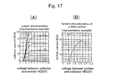
- step SP2 a voltage drop Vt of the transistors and a voltage drop Vd of the diodes are calculated by using the measured current value and the rated characteristics illustrated in Figs. 17(A) and 17(B).
- step SP3 a voltage V0 prior to correction is calculated by multiplying the duty ratio to the DC voltage.
- step SP4 an output voltage of the inverter is calculated by subtracting the voltage drop Vt of the transistors and the voltage drop Vd of the diodes from the voltage V0 prior to correction.
- a measured resistance value at calibration is R t0
- a constant differing according to the model is a
- a resistance value (catalog value, measurement value, or the like) of a power line is ⁇
- the following equations are preferably employed so that the affection due to the resistance value of the power line is corrected so as to improve temperature estimation accuracy.
- Fig. 18 is a flowchart useful in understanding temperature correction based upon an inductance determined by a rotor position.
- step SP1 a rotor position of a DC motor is detected by using the conventional method.
- step SP2 an inductance L of a phase used for temperature detection is calculated by using the conventional method, from the detected rotor position.
- a temperature is calculated by carrying out the operation of To+ ⁇ T by previously obtaining the temperature correction value ⁇ T due to the inductance L and by supposing a temperature obtained from only the resistance value to be To, the temperature correction value ⁇ T being obtained by using the relationship between an inductance L and a calculated temperature, as is illustrated in Fig. 19.
- an inductance L affects a current value such that a current amplitude becomes smaller when an inductance L becomes greater, and that a current amplitude becomes greater when an inductance L becomes smaller, so that an operation point on the rated characteristics is changed. Therefore, temperature estimation accuracy is improved by carrying out the correction processing described above.
- current measurement is carried out at the center of ON-time or OFF-time (for example, at the timing at 1/2 of the ON-time or at the timing at 1/2 of the OFF-time), as is illustrated in Fig. 20, for example.
- This current measurement is effective for a case where an average current is not measured. In this case, variation in current measurement is greatly suppressed.
- current detection is carried out without switching of transistors of an inverter by outputting a voltage of about 5 volts by using a PAM (Pulse Amplitude Modulation) circuitry, as is illustrated in Fig. 21.
- PAM Pulse Amplitude Modulation
Landscapes
- Engineering & Computer Science (AREA)
- Power Engineering (AREA)
- Physics & Mathematics (AREA)
- General Physics & Mathematics (AREA)
- Control Of Motors That Do Not Use Commutators (AREA)
- Inverter Devices (AREA)
Applications Claiming Priority (3)
| Application Number | Priority Date | Filing Date | Title |
|---|---|---|---|
| JP2003365130 | 2003-10-24 | ||
| JP2004004905A JP4501433B2 (ja) | 2003-10-24 | 2004-01-13 | Dcモータのコイル温度推定方法およびその装置 |
| PCT/JP2004/015680 WO2005041397A1 (fr) | 2003-10-24 | 2004-10-22 | Procede d'estimation de temperature de bobine de moteur a courant continu, procede de commande de moteur a courant continu et dispositifs associes |
Publications (2)
| Publication Number | Publication Date |
|---|---|
| EP1677411A1 true EP1677411A1 (fr) | 2006-07-05 |
| EP1677411A4 EP1677411A4 (fr) | 2016-05-25 |
Family
ID=34525450
Family Applications (1)
| Application Number | Title | Priority Date | Filing Date |
|---|---|---|---|
| EP04792822.1A Withdrawn EP1677411A4 (fr) | 2003-10-24 | 2004-10-22 | Procede d'estimation de temperature de bobine de moteur a courant continu, procede de commande de moteur a courant continu et dispositifs associes |
Country Status (4)
| Country | Link |
|---|---|
| US (1) | US7265954B2 (fr) |
| EP (1) | EP1677411A4 (fr) |
| JP (1) | JP4501433B2 (fr) |
| WO (1) | WO2005041397A1 (fr) |
Cited By (11)
| Publication number | Priority date | Publication date | Assignee | Title |
|---|---|---|---|---|
| WO2009115148A2 (fr) * | 2008-03-20 | 2009-09-24 | Robert Bosch Gmbh | Moteur électrique à système de détection de température et procédé de détection d'une température dans un moteur électrique |
| GB2473803A (en) * | 2009-07-02 | 2011-03-30 | Pg Drives Technology Ltd | Prevention of motor overload by calculation of motor resitance and temperature |
| FR2977412A1 (fr) * | 2011-06-30 | 2013-01-04 | Schneider Toshiba Inverter | Procede de commande mis en oeuvre dans un variateur de vitesse pour le prechauffage d'un moteur electrique |
| WO2014006368A2 (fr) * | 2012-07-03 | 2014-01-09 | Dyson Technology Limited | Commande d'un moteur sans balai |
| EP2743713A1 (fr) * | 2012-12-11 | 2014-06-18 | Nidec SR Drives Ltd. | Estimation de résistance dans des machines électriques |
| CN103904977A (zh) * | 2014-03-26 | 2014-07-02 | 哈尔滨工程大学 | 一种pwm驱动电机系统共模干扰噪声源阻抗的估算方法 |
| US9160255B2 (en) | 2012-07-03 | 2015-10-13 | Dyson Technology Limited | Method of preheating a brushless motor |
| EP2725331A3 (fr) * | 2012-10-26 | 2016-04-20 | Diehl AKO Stiftung & Co. KG | Procédé et dispositif de détermination d'une température de service d'un moteur électrique |
| FR3075514A1 (fr) * | 2017-12-18 | 2019-06-21 | Somfy Activites Sa | Procede d’estimation de la temperature interne d’une machine tournante , unite electronique de controle, actionneur et dispositif domotique associes |
| EP3490138A4 (fr) * | 2016-07-21 | 2020-01-01 | Nidec Corporation | Module de moteur, dispositif de commande de moteur, dispositif et procédé d'estimation de température |
| EP3817213A1 (fr) * | 2019-10-31 | 2021-05-05 | VAF GmbH | Dispositif de chauffage électrique pour un composant comprenant au moins un enroulement et procédé pour faire fonctionner un tel dispositif de chauffage |
Families Citing this family (38)
| Publication number | Priority date | Publication date | Assignee | Title |
|---|---|---|---|---|
| DE102004056998A1 (de) * | 2004-11-25 | 2006-06-08 | Siemens Ag | Verfahren und Vorrichtung zur Variation eines Nennstroms |
| DE602006018670D1 (de) | 2005-01-28 | 2011-01-13 | Oji Paper Co | Tintenstrahlaufzeichnungsmaterial |
| JP4854993B2 (ja) * | 2005-06-23 | 2012-01-18 | 株式会社日立産機システム | 永久磁石式回転電機の制御装置および永久磁石式回転電機の温度推定方法 |
| US8604803B2 (en) * | 2006-05-19 | 2013-12-10 | Pratt & Whitney Canada Corp. | System and method for monitoring temperature inside electric machines |
| US7825621B2 (en) * | 2007-08-28 | 2010-11-02 | Rockwell Automation Technologies, Inc. | Junction temperature reduction for three phase inverters modules |
| JP4535209B2 (ja) * | 2008-04-14 | 2010-09-01 | 株式会社村田製作所 | 無線icデバイス、電子機器及び無線icデバイスの共振周波数の調整方法 |
| JP4598100B2 (ja) * | 2008-04-17 | 2010-12-15 | 三菱電機株式会社 | 変速機の制御装置 |
| FR2933550B1 (fr) * | 2008-07-01 | 2012-10-12 | Schneider Toshiba Inverter Europe Sas | Procede de determination des inductances d'une machine synchrone a aimants permanents |
| US7791328B2 (en) | 2008-07-03 | 2010-09-07 | Emerson Electric Co. | Method and system for calibrating a motor control circuit to improve temperature measurement in an electrical motor |
| JP4659874B2 (ja) | 2008-11-20 | 2011-03-30 | 三菱電機株式会社 | 自動変速機の制御装置 |
| NZ588233A (en) | 2010-09-28 | 2011-06-30 | Dynamic Controls | Dynamically adjusting a compensation term based on a stored profile for a motor |
| JP5264871B2 (ja) * | 2010-12-09 | 2013-08-14 | 三菱電機株式会社 | 空気調和機 |
| JP5603807B2 (ja) * | 2011-03-07 | 2014-10-08 | Ntn株式会社 | 電気自動車用駆動モータの診断装置および診断方法並びに電気自動車用駆動モータの診断装置を備えた電気自動車 |
| JP2012202252A (ja) * | 2011-03-24 | 2012-10-22 | Sanyo Electric Co Ltd | スクロール圧縮装置 |
| DE102011077237A1 (de) * | 2011-06-08 | 2012-12-13 | Robert Bosch Gmbh | Verfahren zum Bestimmen einer Temperatur von Kraftstoff in einem Kraftstofftank |
| US9166518B2 (en) * | 2011-06-27 | 2015-10-20 | GM Global Technology Operations LLC | Rotor temperature estimation for an electric vehicle |
| US8662620B2 (en) | 2011-11-21 | 2014-03-04 | Xerox Corporation | Indirect temperature monitoring for thermal control of a motor in a printer |
| CN103813236A (zh) | 2012-11-07 | 2014-05-21 | 飞兆半导体公司 | 扬声器保护的相关方法及装置 |
| WO2015011944A1 (fr) | 2013-07-23 | 2015-01-29 | アイシン・エィ・ダブリュ株式会社 | Dispositif d'entraînement |
| US9634590B2 (en) | 2013-07-23 | 2017-04-25 | Aisin Aw Co., Ltd. | Drive device |
| WO2015011945A1 (fr) * | 2013-07-23 | 2015-01-29 | アイシン・エィ・ダブリュ株式会社 | Dispositif d'entraînement |
| JP6268857B2 (ja) * | 2013-07-23 | 2018-01-31 | アイシン・エィ・ダブリュ株式会社 | 駆動装置 |
| DE102014005706B4 (de) * | 2014-04-22 | 2023-02-02 | Diehl Ako Stiftung & Co. Kg | Verfahren und Vorrichtung zum Betreiben eines Elektromotors |
| US9236828B1 (en) | 2014-07-03 | 2016-01-12 | Rockwell Automation Technologies, Inc. | Methods and power conversion system control apparatus to control IGBT junction temperature at low speed |
| CN104158463B (zh) * | 2014-09-05 | 2016-03-30 | 南车株洲电力机车研究所有限公司 | 一种永磁同步电机的转子温度监测方法及系统 |
| US9318976B1 (en) | 2014-10-30 | 2016-04-19 | Rockwell Automation Technologies, Inc. | Adjustable PWM method to increase low speed starting torque and inverter voltage measurement accuracy |
| KR101821104B1 (ko) * | 2015-04-07 | 2018-01-22 | 닛산 지도우샤 가부시키가이샤 | 비접촉 수전 장치의 온도 추정 장치 및 온도 추정 방법 |
| WO2016185924A1 (fr) * | 2015-05-20 | 2016-11-24 | 三菱電機株式会社 | Dispositif de conversion de courant et système d'entraînement de véhicule auquel ce dernier est appliqué |
| US9568704B1 (en) | 2015-08-17 | 2017-02-14 | Apple Inc. | Temperature based control of voice coil motor |
| US9807528B1 (en) * | 2015-09-21 | 2017-10-31 | Apple Inc. | Electronic devices and method for thermal monitoring of an electro-mechanical actuator |
| US9932701B2 (en) | 2015-12-29 | 2018-04-03 | Whirlpool Corporation | Laundry appliances using search coils to identify motors and their rotors in order to self-tune control of the motor |
| JP6477578B2 (ja) * | 2016-04-20 | 2019-03-06 | トヨタ自動車株式会社 | モータ温度推定装置 |
| DK3625528T3 (da) | 2017-05-18 | 2022-06-13 | Gen Electric | System og fremgangsmåde til estimering af motortemperatur på et pitch-system af en vindmølle |
| CN109601022B (zh) * | 2017-07-28 | 2020-10-09 | 三菱电机株式会社 | 逆变器装置及逆变器装置的异常检测方法 |
| DE102018117262A1 (de) * | 2018-07-17 | 2020-01-23 | Ebm-Papst Mulfingen Gmbh & Co. Kg | Motorenidentifikation |
| KR102569255B1 (ko) * | 2018-10-23 | 2023-08-23 | 에이치엘만도 주식회사 | 모터 제어 장치 및 모터 제어 방법 |
| US10784797B1 (en) | 2019-06-19 | 2020-09-22 | Rockwell Automation Technologies, Inc. | Bootstrap charging by PWM control |
| US11336206B2 (en) | 2020-09-23 | 2022-05-17 | Rockwell Automation Technoligies, Inc. | Switching frequency and PWM control to extend power converter lifetime |
Family Cites Families (17)
| Publication number | Priority date | Publication date | Assignee | Title |
|---|---|---|---|---|
| JPS61180592A (ja) * | 1985-02-05 | 1986-08-13 | Mitsubishi Electric Corp | 査導電動機の制御装置 |
| DE3706659A1 (de) * | 1987-03-02 | 1988-09-15 | Heidelberger Druckmasch Ag | Einrichtung zum erfassen der wicklungstemperatur eines insbesondere buerstenlosen gleichstrommotors |
| JPH01248927A (ja) | 1988-03-29 | 1989-10-04 | Aisin Seiki Co Ltd | Pwm制御モータの異常検出装置 |
| JPH048192A (ja) * | 1990-04-25 | 1992-01-13 | Hitachi Ltd | 電動機の抵抗値測定方法とその装置および電気車の制御方法とその装置 |
| US5510687A (en) * | 1994-04-29 | 1996-04-23 | Allen-Bradley Company, Inc. | Electric motor controller with temperature protection |
| US5539601A (en) * | 1994-05-12 | 1996-07-23 | Siemens Energy & Automation, Inc. | Apparatus and method for thermal protection of electric motors |
| DE69806109T2 (de) * | 1997-09-05 | 2002-11-07 | Mitsubishi Denki K.K., Tokio/Tokyo | Steuersystem für elektrische Servolenkung |
| JP3297371B2 (ja) * | 1998-03-12 | 2002-07-02 | 株式会社東芝 | 電気車の制御装置 |
| JP3715136B2 (ja) * | 1999-06-03 | 2005-11-09 | トヨタ自動車株式会社 | 電動パワーステアリング装置 |
| JP4816838B2 (ja) | 2000-07-13 | 2011-11-16 | 株式会社安川電機 | 誘導電動機のベクトル制御装置 |
| JP3502040B2 (ja) * | 2000-12-27 | 2004-03-02 | 本田技研工業株式会社 | ブラシレスdcモータの定数検出装置およびブラシレスdcモータの制御装置およびブラシレスdcモータの定数検出用プログラム |
| JP3511018B2 (ja) * | 2001-05-18 | 2004-03-29 | 松下電器産業株式会社 | リニアコンプレッサ駆動装置 |
| JP2002367307A (ja) | 2001-06-13 | 2002-12-20 | Hitachi Ltd | 磁気ディスク装置 |
| JP4232358B2 (ja) * | 2001-06-26 | 2009-03-04 | ダイキン工業株式会社 | 予熱発生機構 |
| JP4391719B2 (ja) * | 2002-03-20 | 2009-12-24 | トヨタ自動車株式会社 | モータ温度推定装置およびモータ制御装置 |
| JP4023249B2 (ja) * | 2002-07-25 | 2007-12-19 | ダイキン工業株式会社 | 圧縮機内部状態推定装置及び空気調和装置 |
| JP3694007B2 (ja) * | 2003-06-03 | 2005-09-14 | シャープ株式会社 | 液晶表示パネル |
-
2004
- 2004-01-13 JP JP2004004905A patent/JP4501433B2/ja not_active Expired - Fee Related
- 2004-10-22 US US10/576,769 patent/US7265954B2/en not_active Expired - Fee Related
- 2004-10-22 EP EP04792822.1A patent/EP1677411A4/fr not_active Withdrawn
- 2004-10-22 WO PCT/JP2004/015680 patent/WO2005041397A1/fr active Application Filing
Non-Patent Citations (1)
| Title |
|---|
| See references of WO2005041397A1 * |
Cited By (16)
| Publication number | Priority date | Publication date | Assignee | Title |
|---|---|---|---|---|
| WO2009115148A2 (fr) * | 2008-03-20 | 2009-09-24 | Robert Bosch Gmbh | Moteur électrique à système de détection de température et procédé de détection d'une température dans un moteur électrique |
| GB2473803A (en) * | 2009-07-02 | 2011-03-30 | Pg Drives Technology Ltd | Prevention of motor overload by calculation of motor resitance and temperature |
| FR2977412A1 (fr) * | 2011-06-30 | 2013-01-04 | Schneider Toshiba Inverter | Procede de commande mis en oeuvre dans un variateur de vitesse pour le prechauffage d'un moteur electrique |
| US9160255B2 (en) | 2012-07-03 | 2015-10-13 | Dyson Technology Limited | Method of preheating a brushless motor |
| WO2014006368A2 (fr) * | 2012-07-03 | 2014-01-09 | Dyson Technology Limited | Commande d'un moteur sans balai |
| US10756653B2 (en) | 2012-07-03 | 2020-08-25 | Dyson Technology Limited | Control of a brushless motor |
| WO2014006368A3 (fr) * | 2012-07-03 | 2014-06-19 | Dyson Technology Limited | Commande d'un moteur sans balai |
| EP2725331A3 (fr) * | 2012-10-26 | 2016-04-20 | Diehl AKO Stiftung & Co. KG | Procédé et dispositif de détermination d'une température de service d'un moteur électrique |
| EP2743713A1 (fr) * | 2012-12-11 | 2014-06-18 | Nidec SR Drives Ltd. | Estimation de résistance dans des machines électriques |
| US9575104B2 (en) | 2012-12-11 | 2017-02-21 | Nidec Sr Drives Ltd. | Estimation of resistance in electrical machines |
| CN103869170A (zh) * | 2012-12-11 | 2014-06-18 | 尼得科Sr驱动有限公司 | 电机中电阻的估算 |
| CN103904977A (zh) * | 2014-03-26 | 2014-07-02 | 哈尔滨工程大学 | 一种pwm驱动电机系统共模干扰噪声源阻抗的估算方法 |
| EP3490138A4 (fr) * | 2016-07-21 | 2020-01-01 | Nidec Corporation | Module de moteur, dispositif de commande de moteur, dispositif et procédé d'estimation de température |
| FR3075514A1 (fr) * | 2017-12-18 | 2019-06-21 | Somfy Activites Sa | Procede d’estimation de la temperature interne d’une machine tournante , unite electronique de controle, actionneur et dispositif domotique associes |
| WO2019121662A1 (fr) * | 2017-12-18 | 2019-06-27 | Somfy Activites Sa | Procede d'estimation de la temperature interne d'une machine tournante, unite electronique de controle, actionneur et dispositif domotique associes |
| EP3817213A1 (fr) * | 2019-10-31 | 2021-05-05 | VAF GmbH | Dispositif de chauffage électrique pour un composant comprenant au moins un enroulement et procédé pour faire fonctionner un tel dispositif de chauffage |
Also Published As
| Publication number | Publication date |
|---|---|
| EP1677411A4 (fr) | 2016-05-25 |
| JP4501433B2 (ja) | 2010-07-14 |
| WO2005041397A1 (fr) | 2005-05-06 |
| US7265954B2 (en) | 2007-09-04 |
| JP2005151790A (ja) | 2005-06-09 |
| US20070070560A1 (en) | 2007-03-29 |
Similar Documents
| Publication | Publication Date | Title |
|---|---|---|
| US7265954B2 (en) | Method for estimating DC motor coil temperature, DC motor control method and their devices | |
| KR101386939B1 (ko) | 가변 버스 전압에 의한 역률 보정 | |
| EP2290793B1 (fr) | Dispositif convertisseur, module de commande de moteur, appareil réfrigérant et dispositif de réduction harmonique | |
| KR101341874B1 (ko) | 모터 파라미터를 추정, 관리 및 진단하기 위한 제어기 및 방법 | |
| CN100581047C (zh) | 压缩机预热控制装置及方法 | |
| KR101312328B1 (ko) | 제어 각도 사이의 트랜지션용 제어기 및 방법 | |
| US8525508B2 (en) | Method for calibrating a motor control circuit to improve temperature measurement in an electrical motor | |
| JP6217369B2 (ja) | モータ制御装置及びモータ制御方法 | |
| CN101960712A (zh) | 逆变器装置 | |
| KR20080068254A (ko) | 인버터의 입력전류 검출장치 및 그 방법 | |
| US9923505B2 (en) | Methods and systems for controlling an electric motor | |
| US6362593B1 (en) | Apparatus and method for compensating dead time of motor | |
| JP6651188B1 (ja) | 電動機の減磁検出方法 | |
| US11984822B2 (en) | Power conversion apparatus | |
| KR20210092540A (ko) | 전력 변환 장치 및 이를 이용하는 공기 조화기 | |
| JP2005218275A (ja) | モータのコイル温度検出装置 | |
| KR100839073B1 (ko) | 인버터 회로의 입력전류 검출장치 및 그 방법 | |
| JP2007053895A (ja) | インバータ装置 | |
| JP6476001B2 (ja) | モータ駆動装置 | |
| KR100266579B1 (ko) | 인버터일체형유도전동기제어장치 | |
| US11146205B2 (en) | Method for controlling electric motors, corresponding circuit and computer program product | |
| JP3661388B2 (ja) | インバータ装置 | |
| JP4631575B2 (ja) | インバータ装置 | |
| US7973510B2 (en) | Apparatus for controlling inverter | |
| JP2004336871A (ja) | 電動機駆動装置の入力電流検出方法および制御方法 |
Legal Events
| Date | Code | Title | Description |
|---|---|---|---|
| PUAI | Public reference made under article 153(3) epc to a published international application that has entered the european phase |
Free format text: ORIGINAL CODE: 0009012 |
|
| 17P | Request for examination filed |
Effective date: 20060419 |
|
| AK | Designated contracting states |
Kind code of ref document: A1 Designated state(s): AT BE BG CH CY CZ DE DK EE ES FI FR GB GR HU IE IT LI LU MC NL PL PT RO SE SI SK TR |
|
| DAX | Request for extension of the european patent (deleted) | ||
| RA4 | Supplementary search report drawn up and despatched (corrected) |
Effective date: 20160425 |
|
| RIC1 | Information provided on ipc code assigned before grant |
Ipc: G01K 7/00 20060101ALI20160419BHEP Ipc: H02P 23/14 20060101ALI20160419BHEP Ipc: H02P 29/00 20160101ALI20160419BHEP Ipc: F25B 1/00 20060101ALI20160419BHEP Ipc: H02P 6/00 20160101AFI20160419BHEP |
|
| 17Q | First examination report despatched |
Effective date: 20180315 |
|
| STAA | Information on the status of an ep patent application or granted ep patent |
Free format text: STATUS: THE APPLICATION IS DEEMED TO BE WITHDRAWN |
|
| 18D | Application deemed to be withdrawn |
Effective date: 20190212 |