EP1675384A2 - Bildverarbeitungsvorrichtung, -verfahren und Bildaufnahmevorrichtung - Google Patents
Bildverarbeitungsvorrichtung, -verfahren und Bildaufnahmevorrichtung Download PDFInfo
- Publication number
- EP1675384A2 EP1675384A2 EP05257890A EP05257890A EP1675384A2 EP 1675384 A2 EP1675384 A2 EP 1675384A2 EP 05257890 A EP05257890 A EP 05257890A EP 05257890 A EP05257890 A EP 05257890A EP 1675384 A2 EP1675384 A2 EP 1675384A2
- Authority
- EP
- European Patent Office
- Prior art keywords
- image
- light image
- visible light
- invisible light
- pass filter
- Prior art date
- Legal status (The legal status is an assumption and is not a legal conclusion. Google has not performed a legal analysis and makes no representation as to the accuracy of the status listed.)
- Withdrawn
Links
Images


Classifications
-
- H—ELECTRICITY
- H04—ELECTRIC COMMUNICATION TECHNIQUE
- H04N—PICTORIAL COMMUNICATION, e.g. TELEVISION
- H04N1/00—Scanning, transmission or reproduction of documents or the like, e.g. facsimile transmission; Details thereof
- H04N1/40—Picture signal circuits
- H04N1/409—Edge or detail enhancement; Noise or error suppression
-
- H—ELECTRICITY
- H04—ELECTRIC COMMUNICATION TECHNIQUE
- H04N—PICTORIAL COMMUNICATION, e.g. TELEVISION
- H04N23/00—Cameras or camera modules comprising electronic image sensors; Control thereof
- H04N23/80—Camera processing pipelines; Components thereof
- H04N23/81—Camera processing pipelines; Components thereof for suppressing or minimising disturbance in the image signal generation
-
- H—ELECTRICITY
- H04—ELECTRIC COMMUNICATION TECHNIQUE
- H04N—PICTORIAL COMMUNICATION, e.g. TELEVISION
- H04N1/00—Scanning, transmission or reproduction of documents or the like, e.g. facsimile transmission; Details thereof
- H04N1/40—Picture signal circuits
-
- H—ELECTRICITY
- H04—ELECTRIC COMMUNICATION TECHNIQUE
- H04N—PICTORIAL COMMUNICATION, e.g. TELEVISION
- H04N23/00—Cameras or camera modules comprising electronic image sensors; Control thereof
- H04N23/10—Cameras or camera modules comprising electronic image sensors; Control thereof for generating image signals from different wavelengths
- H04N23/11—Cameras or camera modules comprising electronic image sensors; Control thereof for generating image signals from different wavelengths for generating image signals from visible and infrared light wavelengths
-
- H—ELECTRICITY
- H04—ELECTRIC COMMUNICATION TECHNIQUE
- H04N—PICTORIAL COMMUNICATION, e.g. TELEVISION
- H04N23/00—Cameras or camera modules comprising electronic image sensors; Control thereof
- H04N23/80—Camera processing pipelines; Components thereof
Definitions
- the present invention contains subject matter related to Japanese Patent Application JP 2004-371985 filed in the Japanese Patent Office on December 22, 2004.
- This invention relates to the field of image processing apparatus, image processing methods, image pickup apparatus, computer programs and recording medium.
- Illustrative embodiments relate to the field of image processing apparatus, image processing methods, image pickup apparatus, computer programs and recording medium adapted to eliminate or at least reduce noises, while storing edges of images.
- the color tone of the image depends on lighting to a large extent.
- the picked up image of a subject bears an orangey color tone when the subject is irradiated with candle light but bears a bluish color tone when it is irradiated with moon light.
- Images of a subject may be picked up with completely different color tones on the same site depending on lighting.
- the picked up image When picking up an image, it is possible to correctly reproduce the original color tone by utilizing natural light without using lighting equipment such as a flash bulb.
- the picked up image contains noises to a considerable extent when the subject is shot indoors or at night because of insufficient exposure to light.
- flash light is used for imaging, the edges of the objects and other details in the picked up image appear clearly but the color tone of the image may not be accurate and/or shades and high lights that do not actually exist may also appear.
- the image processing apparatus 11 includes a pair of low pass filters 12, 13, a high pass filter 14, a pair of image synthesizing sections 15, 17 and a single shadow extracting section 16.
- the low pass filter 13 is a cross bilateral filter that detects edges from an image picked up by using flash light (to be referred to as flash image hereinafter) and remove noises from an image picked up without using flash light (to be referred to as natural light image hereinafter).
- the high pass filter 14 extracts edges of objects in the picked up image. For extracting edges, the image processing apparatus executes a process of dividing each pixel value in the natural light image by the corresponding one of the flash image.
- the image synthesizing section 15 synthetically combines the natural light image from which noises are removed by the low pass filter 13 and the flash image from which edges are extracted by the high pass filter 14 to generate a synthetic image Comp.
- the image processing apparatus executes a process of multiplying each pixel value of the low pass filter 13 by the corresponding one of the output image of the high pass filter 14.
- the synthetic image Comp provides the advantages of the flash image and those of the natural light image so that its color tone is accurate and it contains fewer noises.
- the low pass filter 12 removes noises from the natural light image.
- a bilateral filter is used for the low pass filter 12.
- a bilateral filter can detect edges and remove noises from a single image.
- the shadow extracting section 16 extracts differences between the two images including the flash image and the natural light image and evaluates the probability by which the flash image is changed from the natural light image by high lights and shadows.
- the image synthesizing section 17 carries out an operation of weighted addition of the output image from the low pass filter 12 and the output image Comp of the image synthesizing section 15 according to the outcome of the evaluation of the shadow extracting section 16. More specifically, the image synthesizing section 17 raises the weight of the image in a part thereof where shadows and high lights may highly probably have been produced by flash light and reduces the weight of the image in a part hereof where they may probably have not been produced. On the other hand, the image synthesizing section 17 removes unnecessary shadows and high lights from the synthetic image Comp and generates an output image Out.
- the known image processing apparatus 11 can obtain an image where edges in a flash image and the color tone of a corresponding natural light image are optimally blended by generating two images including an image where edges are synthesized from a flash image and an image from which noises are removed without referring to the edges of the flash image, raising the coefficient of the output image of the high pass filter 12 for pixels where shadows and high lights may highly probably have been produced by flash light and reducing the coefficient of the output image Comp of the image synthesizing section 17 for pixels where shadows and high lights may probably have not been produced (see, for example, Non-Patent Document 1: Georg Petschnigg et al, Digital Photography with Flash and No-Flash Image pairs, acm Transaction on Graphics, Vol. 23, Number 3, pp. 664-672, August 2004).
- edges and details of an image become clear when flash light is used for picking up the image
- shadows and high lights that do not exist in a corresponding natural light image can appear as described above.
- the image processing apparatus 11 requires two images including a flash image and a natural light image. Since it is not possible to pick up a flash image and a natural light image at the same time, the technique of obtaining two images cannot be applied to moving pictures and to operations of picking up a moving subject. Still additionally, it is not possible to obtain a flash image in areas where the use of flashlight is prohibited.
- embodiments of the present invention seek to provide an image processing apparatus, an image processing method, an image pickup apparatus, a computer program and a recording medium that can reduce noises in an image picked up in natural light without using lighting equipment that affect the picked up image.
- a first aspect of the present invention provides an image processing apparatus including: an image acquisition means for acquiring a visible light image and an invisible light image corresponding to the visible light image; and a noise reduction means for reducing noises of the visible light image by using the invisible light image.
- an image pickup apparatus including: a visible light image pickup means for picking up a visible light image according to a first spectral characteristic of having sensitivity mainly relative to visible light; an invisible light image pickup means for picking up an invisible light image according to a second spectral characteristic of having sensitivity mainly to invisible light; an aberration correction means for correcting the aberration of the visible light image and that of the invisible light image; and a noise reduction means for reducing noises of the visible light image by using the invisible light image.
- an image processing method including: an image acquisition step of acquiring a visible light image and an invisible light image corresponding to the visible light image and picked up with the same number of pixel as those of the visible light image; and a noise reduction step of reducing noises of the visible light image by using the invisible light image.
- a computer program for causing a computer to execute a predetermined process, the program including: an image acquisition step of acquiring a visible light image and an invisible light image corresponding to the visible light image and picked up with the same number of pixel as those of the visible light image; and a noise reduction step of reducing noises of the visible light image by using the invisible light image.
- a recording medium where a computer program for causing a computer to execute a predetermined process, the program including: an image acquisition step of acquiring a visible light image and an invisible light image corresponding to the visible light image and picked up with the same number of pixel as those of the visible light image; and a noise reduction step of reducing noises of the visible light image by using the invisible light image.
- an invisible light image is a non-visible light image, i.e. an image formed by light having a wavelength not in the visible spectrum.
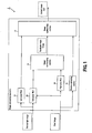
- FIG 2 is a schematic block diagram showing the configuration of the embodiment of image pickup apparatus.
- the image pickup apparatus 1 includes an image pickup section 2 for picking up both a visible light image Visible and an infrared image Infr at a time, an image processing section 3 for removing noises from the visible light image Visible, a memory 4 for providing storage area for storing images and data, a system control section 8 adapted to output images to LCD (liquid crystal display) 5 and exchange data with external recording apparatus 10 by way of interfaces such as serial interface 6 and USB (universal serial bus) 7 and a signal processing section 9 adapted to operate for AGC (automatic gain control) and CDS (correlated double sampling) on the image input from image pickup element 21 and output the image to the image processing section 3.
- AGC automatic gain control
- CDS correlated double sampling
- the image pickup section 2 outputs RGB images including a visible light image Visible and an infrared image Infr.
- the image pickup section 2 includes an image pickup element 21 typically formed by using a CCD (charge coupld device) and a CMOS (complementary Metal-Oxide Semiconductor), a motor 23 for focusing lens 22 and switching the shutter speed 23 and a driver 24 for controlling the motor 23.
- CCD charge coupld device
- CMOS complementary Metal-Oxide Semiconductor
- the image pickup element 21 may include two image pickup elements 21 including one that operates for picking up an infrared image Infr and one that operate for picking up a visible light image Visible.
- the image pickup element 21 for picking up an infrared image Infr and the image pickup element 21 for picking up a visible light image Visible have a same number of pixels and a same view angle and are adapted to be exposed to light simultaneously for a same period of time. Alternatively, it may be so arranged that the output of a single image pickup element 21 is used for both an infrared image Infr and a visible light image Visible.
- the image processing section 3 removes noises from the visible light image Visible input to it and generates an output image Out, preserving edges of the visible light image Visible.
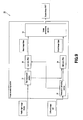
- FIG 3 is a schematic block diagram showing the configuration of the image processing section 3.
- the image processing section 3 includes a gain adjustment section 31 for adjusting the gain of the visible light image Visible, a low pass filter 33 for removing noises from the visible light image Visible, a high pass filter 34 for extracting edges and details of the infrared image Infr and an image synthesizing section 35 for synthetically combining base image Base, which is the output image of the low pass filter 33, and detail image Edge, which is the output image of the high pass filter 34.
- the gain adjustment section 31 boosts the pixel values of the visible light image Visible that may be an underexposed dark image to make it show pixel values close to those of a correctly exposed image.
- Techniques that can be used for gain adjustment include one that multiplies pixel values of the visible light image by a constant and one that involves the use of gamma correction based on an exponential function or some other correction based on a polynominal function. The maximum value is limited for the pixels after adjustment.
- FIG 4 is a schematic block diagram showing the configuration of the low pass filter 33.
- the low pass filter 33 includes an X edge detecting section 41 for detecting edges in the X-direction (transversal direction) of the infrared image Infr, a Y edge detecting section 42 for detecting edges in the Y-direction (longitudinal direction) of the infrared image Infr, an X evaluation value storage section 43 for storing the edge evaluation value of the X-direction, a Y evaluation value storage section 44 for storaging the edge evaluation value of the Y-direction, three X low pass filters 45a, 45b, 45c for removing edges in the X-direction, three low pass filters 46a, 46b, 46c for removing edges in the Y-direction, three X comparator sections 47a, 47b, 47c for comparing the X edge evaluation value with threshold values and three Y comparator sections 48a, 48b, 48c for comparing the Y edge evaluation value with threshold values.
- the X low pass filters are FIR low pass filters with 5 ⁇ 1 taps in the X-direction. Noises are removed in the X-direction from the visible light image by the X low pass filters.
- the Y low pass filters are FIR low pass filters with 1 ⁇ 5 taps in the Y-direction. Noises are removed in the Y-direction from the visible light image by the Y low pass filters.
- the X edge detecting section 41 is an FIR filter with 4 ⁇ 4 taps for detecting edges in the X-direction.
- the Y edge detecting section 42 is an FIR filter with 4x4 taps for detecting edges in the Y-direction.
- the X value storage section 43 computationally determines an edge evaluation value by applying absolute value computations to the filtering outcome of the X edge detecting section 42 and stores the value as X edge image.
- the Y value storage section 44 computationally determines an edge evaluation value by applying absolute value computations to the filtering outcome of the Y edge detecting section 43 and stores the value as Y edge image.
- the X comparator sections 47 and the Y comparator sections 48 compare the respective edge evaluation values with predetermined threshold values. Threshold value n is equal to 1/2 of the largest possible edge evaluation value.
- the X comparator section 47a compares the edge evaluation value in the X-direction with the threshold value n and the X comparator section 47b compares the edge evaluation value in the X-direction with threshold value n/2, whereas the X comparator section 47c compares the edge evaluation value in the X-direction with threshold value n/4.
- the Y comparator section 48a compares the edge evaluation value in the Y-direction with the threshold value n and the Y comparator section 48b compares the edge evaluation value in the Y-direction with threshold value n/2, whereas the Y comparator section 48c compares the edge evaluation value in the Y-direction with threshold value n/4.
- the low pass filter 33 is a three-stage filter including three filters for three different levels including a level 1 filter 49a, a level 2 filter 49b and a level 3 filter 49c.
- the level of the low pass filter 33 depends on the magnitudes of the threshold values of the X comparator sections 47 and the Y comparator sections 48.
- the low pass filter for the threshold value n, the low pass filter for the threshold value n/2 and the low pass filter for the threshold value n/4 are respectively referred to as level 1 filter 49a, level 2 filter 49b and level 3 filter 49c.
- the visible light image Visible is firstly output to the X comparator section 47a.
- the X comparator section 47a compares the edge evaluation value in the X-direction stored in the X evaluation value storage section 43 with the threshold value n.
- the X comparator section 47a outputs the visible light image Visible to the X low pass filter 45a when the edge evaluation value is smaller than the threshold value n but it outputs the visible light image Visible to the Y comparator section 48a when the edge evaluation value is not smaller than the threshold value n.
- the Y comparator section 48b compares the edge evaluation value in the Y-direction stored in the Y evaluation value storage section 44 with the threshold value n.
- the Y comparator section 48a outputs the visible light image Visible to the Y low pass filter 46a when the edge evaluation value is smaller than the threshold value n but it outputs the visible light image Visible to the next X comparator section 47b when the edge evaluation value is not smaller than n.
- the X comparator section 47b, the Y comparator section 46b, the X comparator section 47c and the Y comparator section 48c compare the edge evaluation value with the respective threshold values and outputs the visible light image Visible to the immediately downstream low pass filter when the edge evaluation value is smaller than the respective threshold values but they output the visible light image Visible to the next comparator section when the edge evaluation value is not smaller than the respective threshold values.
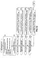
- FIG 5 is a flowchart of operation of the low pass filter 33.
- the low pass filter 33 firstly inputs the infrared image Infr (Step S1).
- the X edge detecting section 41 detects edges that are found in the X-direction in the infrared image Infr.
- the X evaluation value storage section 43 computationally determines the edge evaluation value in the X-direction by applying predetermined absolute value computations to the edges detected in the X-direction and stores the computationally determined edge evaluation value as X edge image (Step S2).
- the Y edge detecting section 42 detects edges that are found in the Y-direction in the infrared image Infr.
- the Y evaluation value storage section 44 computationally determines the edge evaluation value in the Y-direction by applying predetermined absolute value computations to the edges detected in the Y-direction and stores the computationally determined edge evaluation value as Y edge image (Step S3).
- the low pass filter 33 inputs the visible light image Visible from the gain adjustment section 31 (Step S4).
- the low pass filter 33 then applies the input visible light image Visible to the level 1 filter 49a for a process in the X-direction (Step S5).
- FIG 6 is a flowchart of the process of the level 1 filter 49a in the X-direction.
- the level 1 filter 49a firstly initializes the coordinate Y in the Y-direction to 0 (Step S11) and also initializes the coordinate X in the X-direction to 0 (Step S12).
- the X comparator section 47a inputs the X evaluation value image from the X evaluation value storage section 43. Then, the X comparator section 47a compares the edge evaluation value in the X-direction at the coordinates (X, Y) of the X evaluation value image with the threshold value n.
- Step S 13; YES If the edge evaluation value at the coordinates (X, Y) is smaller than the threshold value n (Step S 13; YES), it applies the X low pass filter 45a to the visible light image at the coordinates (X, Y) (Step S 14). On the other hand, if the edge evaluation value at the coordinates (X, Y) is smaller than the threshold value (Step S 13; NO), the process proceeds to Step S 15.
- the level 1 filter 49a increments the value of the X-coordinate by 1 in Step S 15. It then compares the value of the X-coordinate with the width of the visible light image Visible. If the X-coordinate is smaller than the width of the visible light image Visible (Step S16; YES), the process returns to Step S 13.
- the level 1 filter 49a increments the value of the Y-coordinate by 1 (Step S 17).
- the level 1 filter 49a compares the value of the Y-coordinate with the height of the visible light image Visible in Step S 18. If the Y-coordinate is smaller than the height of the visible light image Visible (Step S 18; YES), the process returns to Step S 12. On the other hand, if the Y-coordinate is not smaller than the height of the visible light image Visible (Step S 18; NO), the level 1 filter 49a ends the process in the X-direction.
- the level 1 filter compares the edge evaluation value consisting the visible image with the threshold value n. If the edge evaluation value is smaller than the threshold value n, it removes noises in the X-direction by applying the X low pass filter 45a.
- the level 1 filter 49a in the X-direction uses the Y edge image instead of the X edge image as image to be evaluated and the Y low pass filter 46a instead of the X low pass filter 45a as low pass filter (Step S6).
- the level 1 filter 49a As the level 1 filter 49a completes its own process, it outputs the visible light image Visible to the level 2 filter 49b.
- the level 2 filter 49b executes a process in the X-direction (Step S7). As it completes the process in the X-direction, it then executes another process in the Y-direction (Step S8).
- the level 3 filter 49c receives the output image of the level 2 filter 49b, it executes a process in the X-direction (Step S9) and, as it completes the process in the X-direction, it executes another process in the Y-direction (Step S10).
- the processes executed by the level 2 filter and the level 3 filter are the same except that the two filters use different respective threshold values.
- edge preservation filter A filter having such a functional feature is referred to as edge preservation filter.
- edge preservation filters there are bilateral filters and cross bilateral filters besides those illustrated in FIG 4. Any of these filters may be used for the low pass filter 33.
- the low pass filter 33 outputs an image obtained by removing noises from the visible light image Visible. This image is referred to as base image Base.
- the base image Base provides an advantage that the color tone of the image is correct and a disadvantage that the details of edges are not clear and gives an impression of a blurred image.
- FIG 7 is a schematic block diagram of the high pass filter 34, showing a typical configuration thereof.
- the high pass filter 34 in FIG 7 is a two-dimensional FIR filter.
- the high pass filter 34 is formed by using a low pass filter 71 and a division section 72.
- the low pass filter 71 is typically an edge preservation type low pass filter.
- the low pass filter 71 removes noises from the visible light image Visible and outputs the obtained image to the division section 72.
- the division section 72 divides the infrared image Infr by the output of the low pass filter 71 and extracts the high pass components of the infrared image Infr.
- the image output from the high pass filter 34 preserves the edges and the details of the infrared image Infr. This image is referred to as detail image Edge.
- the image synthesizing section 35 generates a synthetic image by multiplying the base image Base by the detail image Edge.
- This image is the output image OUT of the image processing section 3.
- the output image OUT has the advantages of the base image Base and those of the detail image Edge and is characterized in that it provides the correct color tone and clearly shows details.
- the image pickup apparatus 1 of this embodiment provides an output image OUT by synthetically combining a base image Base obtained by removing noises from a visible light image Visible and a detail image Edge obtained by extracting edges and details of a corresponding infrared image Infr.
- the output image OUT is obtained by removing noises from the visible light image Visible and contains edges and details attenuated by the removal of noises.
- the image processing method of embodiments of the invention can be applied to moving pictures and to operations of picking up a moving subject.
- Known image processing apparatus are adapted to extract edges from a flash image so that the cost of arithmetic operations for removing shadows and high lights that can be produced due to differences of lighting conditions between a natural light image and a flash image is enormous.
- the infrared image Infr can be picked up under lighting conditions same as those of the visible light image Visible. In other words, it is no longer necessary to correct the differences of lighting conditions.
- known image processing apparatus are accompanied by the problem that the pixels of details are discarded when the apparatus mistakes details and edges for high lights.
- the infrared image Infr and the visible light image Visible are picked up under the same lighting conditions so that shadows and high lights would not be produced due to differences of lighting conditions and hence no necessary pixels would be discarded.
- This image processing section 50 detects edges by using the luminance of the visible light image Visible. Since luminance has only a single variable, the cost of arithmetic operations for detecting edges will be much less than that of arithmetic operations for detecting edges from the three variables of RGB. Since human beings are generally sensitive to luminance but not to color components, it is sufficiently effective to detect edges by using luminance.
- FIG 8 is a schematic block diagram of the image processing section 50.
- the image processing section 50 includes a gain adjustment section 52, a matrix section 53, a color low pass filter 54, a luminance low pass filter 55, a high pass filter 56, an image synthesizing section 57 and an inverse matrix section 58.
- the gain adjustment section 52 boosts the pixel values of the visible light image Visible that may be an underexposed dark image to make it show pixel values close to those of a correctly exposed image.
- Techniques that can be used for gain adjustment include one that multiplies pixel values of the visible light image by a constant and one that involves the use of gamma correction based on an exponential function or some other correction based on a polynominal function. The maximum value is limited for the pixels after adjustment.
- the matrix section 53 transforms an RGB image into color images Cb, Cr and a luminance image Yd by means of matrix transformation of the RGB image.
- the color low pass filter 54 removes noises from the color images Cb, Cr.
- a bilateral filter may typically be used for the color low pass filter 54.
- a bilateral filter can detect edges and remove noises from a single image.
- the luminance low pass filter 55 removes noises from the luminance image Yd.
- a cross bilateral filter may typically be used for the luminance low pass filter 55.
- a cross bilateral filter can remove noises from the image that is the object of filtering while preserving the edges detected from the image used for detecting edges.
- the luminance low pass filter 55 detects edges from an infrared image Infr and removes noises from the luminance image Yd.
- the image output from the luminance low pass filter 55 is referred to as base image Base.
- the base image Base has an advantage that the luminance of the image is correct and a disadvantage that it can give an impression of a blurred image because edges and details are not clear.
- the high pass filter 56 extracts edges from the infrared image Infr.
- the image output from the high pass filter 56 preserves edges and details of the infrared image Infr. This image is referred to as detail image Edge.
- the image synthesizing section 57 generates a synthetic image by multiplying the base image Base by the detail image Edge.
- This synthetic image has the advantages of the base image Base and those of the detail image Edge and is characterized in that it provides the correct luminance and clear details and edges.
- the inverse matrix section 58 transforms the luminance image into an RGB image by means of inverse matrix transformation of the synthetic image. This image is the output image OUT of the image processing section.
- the image processing section 50 produces color images Cr, Cb and a luminance image Yd by transforming the RGB image and detects edges only from the luminance image Yd. Since human beings are generally sensitive to luminance but not to color components, it is sufficiently effective to detect edges by using luminance. Since luminance has only a single variable, the cost of arithmetic operations for detecting edges will be much less than that of arithmetic operations for detecting edges from the three variables of RGB.
- this image processing section 30 includes an aberration correcting section 32 for correcting the aberration of an infrared image.
- the configuration of the image processing section 30 is same as that of the image processing section 3 except that the former includes an aberration correcting section 32. Therefore, the components same as those of the image processing section 3 will be denoted by the same reference symbols respectively and will not be described any further.
- the aberration correcting section 32 corrects the aberration that is produced due to the difference of wavelength between infrared rays and rays of visible light.
- FIG 10 shows a configuration of the aberration correcting section 32.
- the aberration correcting section 32 includes a matrix section 61, an error computing bilinear scaler 62, an aberration correcting bilinear scaler 63, a parameter computing section 64 and an error computing section 65.
- the matrix section 61 generates a luminance image Yd from the input visible light image Visible.
- the error computing bilinear scaler 62 generates five different scale transformation images and distortion transformation images on the basis of the scale values and the distortion values output from the parameter computing section 64.
- the error computing section 65 compares the scale transformation images and the infrared image and the distortion transformation images and the infrared image and computes the error values of the images.
- the error values are PSNR values (peak signal to noise ratio).
- the parameter computing section 64 optimizes the scale values and the distortion values by referring to the PSNR values computed by the error computing section 65.
- the aberration correcting bilinear scaler 63 corrects the aberration of the visible light image Visible, using the scale value and the distortion value optimized by the parameter computing section 64.
- FIG 11 is a flowchart of operation of the aberration correcting section 32.
- the aberration correcting section 32 inputs the visible light image Visible and the infrared image Infr.
- the visible light image Visible is an RGB image (Step S21).
- the matrix section 61 multiplies the visible light image Visible by a matrix to generate a luminance image Yd (Step S22).
- the parameter computing section 64 initializes the maximum value, the current value and the minimum value of the scale value and the maximum value, the current value and the minimum value of the distortion value (Step S23).
- the parameter computing section 64 inputs the PSNR values from the error computing section 65 and determines the scale value that maximizes the PSNR values (Step S24).
- FIG 12 is a flowchart of the scale value computing process.
- the parameter computing section 64 prepares five parameters including the maximum value S 1 of the scale value, the median value S2 of the maximum value and the current value, the current value S3, the median value S4 of the minimum value and the current value and the minimum value S5.
- the error detecting bilinear scaler 62 carries out a scale transformation of the luminance image Yd, using the five scale values. As a result, five luminance images Yd1 through Yd5 are generated to correspond to the five parameters (Step S31).
- the error computing section 65 compares the luminance images Yd1 through Yd5 and the infrared image Infr to determine five PSNR values (Step S32). If the PSNR value of the luminance image Yd1 generated by the scale transformation, using the maximum value S1 and that of the infrared image Infr, are largest (Step S33; YES), the parameter computing section 64 replaces the current value S3 with the maximum value S 1 and the maximum value S 1 with the value obtained by doubling the maximum value S 1 and subtracting the minimum value S5 from the doubled maximum value S 1 (Step S34).
- Step S35 If the PSNR value is largest for the median value of the maximum value S 1 and the current value S3 (Step S35; YES), the parameter computing section 64 replaces the maximum value S5 with the current value S3 and the current value S3 with the median value of the maximum value S 1 and the current value S3 (Step S36).
- the parameter computing section 64 replaces the maximum value S1 with the current value S3 and the current value S3 with the median value of the current value S3 and the minimum value S5 (Step S38).
- the parameter computing section 64 replaces the current value S3 with the minimum value S5 and the minimum value S5 with the value obtained by doubling the maximum value S5 and subtracting the maximum value S1 from the doubled minimum value S5 (Step S40).
- Step S33, Step S35, Step S37, Step S39; NO) If the PSNR value is largest for the minimum value S5 (Step S33, Step S35, Step S37, Step S39; NO), the parameter computing section 64 replaces the current value S3 with the minimum value S5 and the minimum value S5 with the value obtained by doubling the minimum value S5 and subtracting the maximum value S5 from the doubled minimum value S5 (Step S41). In this way, the process of optimizing the scale value is completed.
- the parameter computing section 64 optimizes the distortion value.
- the process of optimizing a distortion value is identical with the process of optimizing a scale value.
- parameters are converted from scale values to distortion values (Step S25).
- the parameter computing section 64 compares the extent of improvement of the PSNR value with a predetermined threshold value. If the extent of improvement of the PSNR value is not greater than a predetermined threshold value (Step S26; NO), the processing operation returns to Step S25 to repeat the process of optimizing the scale value and the distortion value.
- the parameter computing section 64 If, on the other hand, the extent of improvement is greater than the predetermined threshold value (Step S26; YES), the parameter computing section 64 outputs the current scale value and distortion value to the aberration correcting bilinear scaler 63.
- the aberration correcting bilinear scaler 63 corrects the aberration of the visible light image Visible, using the current scale value and distortion value (Step S27), and outputs the corrected image to the high pass filter 56 (Step S28).
- the aberration correcting section 32 Due to the provision of the aberration correcting section 32, it is now possible to correct the difference of aberration that is produced by the difference of wavelength between rays of visible light and infrared rays. As a result, the image picked up as visible light image Visible and the image picked up as infrared image Infr agree with each other.
- the refractive index of infrared rays is high and expanded to a slight extent.
- a large image is obtained by correcting the visible light image Visible so that the distortion of the image will also be boosted. Since there is a tradeoff between the size and the distortion of an image, the corrected image may be different depending on if priority is given to size or to distortion.
- the filtering process and the aberration correcting process of the image processing section 3 may be executed according to a control program.
- a control program may be recorded on the firmware of the image pickup apparatus 1.
- the external recording apparatus 10 may acquire the control program that is recorded in a recording medium in a form readable to the external recording apparatus 10.
- Recording mediums that can be used for recording the control program include those that operate with a magnetic reading system (e.g., magnetic tapes, flexible discs, magnetic cards), those that operate with an optical reading system (e.g., CD-ROMs, MOs, CD-Rs, DVDs) and semiconductor memories (e.g., memory cards, IC cards).
- the control program may be acquired by way of the Internet or some other network.
Applications Claiming Priority (1)
| Application Number | Priority Date | Filing Date | Title |
|---|---|---|---|
| JP2004371985A JP4534756B2 (ja) | 2004-12-22 | 2004-12-22 | 画像処理装置、画像処理方法、撮像装置、プログラム、及び記録媒体 |
Publications (2)
| Publication Number | Publication Date |
|---|---|
| EP1675384A2 true EP1675384A2 (de) | 2006-06-28 |
| EP1675384A3 EP1675384A3 (de) | 2011-11-30 |
Family
ID=36071991
Family Applications (1)
| Application Number | Title | Priority Date | Filing Date |
|---|---|---|---|
| EP05257890A Withdrawn EP1675384A3 (de) | 2004-12-22 | 2005-12-20 | Bildverarbeitungsvorrichtung, -verfahren und Bildaufnahmevorrichtung |
Country Status (5)
| Country | Link |
|---|---|
| US (1) | US7589771B2 (de) |
| EP (1) | EP1675384A3 (de) |
| JP (1) | JP4534756B2 (de) |
| KR (1) | KR101220002B1 (de) |
| CN (1) | CN100442816C (de) |
Cited By (7)
| Publication number | Priority date | Publication date | Assignee | Title |
|---|---|---|---|---|
| DE102008009263B3 (de) * | 2008-02-15 | 2009-06-10 | Siemens Aktiengesellschaft | Verfahren zum automatischen Erkennen, insbesondere bei der Verkehrsüberwachung, von Fahrzeugen oder von Fahrzeugkennzeichen |
| EP2087314A2 (de) * | 2006-11-01 | 2009-08-12 | Sony Corporation | Quanten-nanodot-kamera |
| EP2187621A2 (de) | 2008-11-17 | 2010-05-19 | Samsung Electronics Co., Ltd | Vorrichtung und Verfahren zur Bildverarbeitung |
| DE102009021721A1 (de) * | 2009-05-18 | 2010-11-25 | Osram Opto Semiconductors Gmbh | Optisches Aufzeichnungsgerät zur Aufzeichnung eines Bildes |
| EP2309449A1 (de) * | 2009-10-09 | 2011-04-13 | EPFL Ecole Polytechnique Fédérale de Lausanne | Verfahren zur Herstellung eines vollfarbigen, geglätteten Bildes |
| EP2472847A1 (de) * | 2009-08-24 | 2012-07-04 | Nec Corporation | System, verfahren und programm zur komprimierung dynamischer bildbereiche |
| CN104079908A (zh) * | 2014-07-11 | 2014-10-01 | 上海富瀚微电子股份有限公司 | 红外与可见光图像信号处理方法及其实现装置 |
Families Citing this family (107)
| Publication number | Priority date | Publication date | Assignee | Title |
|---|---|---|---|---|
| US7457477B2 (en) * | 2004-07-06 | 2008-11-25 | Microsoft Corporation | Digital photography with flash/no flash extension |
| US8531562B2 (en) | 2004-12-03 | 2013-09-10 | Fluke Corporation | Visible light and IR combined image camera with a laser pointer |
| US8385671B1 (en) * | 2006-02-24 | 2013-02-26 | Texas Instruments Incorporated | Digital camera and method |
| SE531942C2 (sv) * | 2007-02-01 | 2009-09-15 | Flir Systems Ab | Metod för bildbehandling av IR-bilder innefattande kontrastförhöjande filtrering |
| JP2008233381A (ja) * | 2007-03-19 | 2008-10-02 | Fujifilm Corp | 撮像装置 |
| JP4316629B2 (ja) * | 2007-03-29 | 2009-08-19 | 株式会社東芝 | 画像処理システム、画像取得方法及びプログラム |
| JP4757221B2 (ja) * | 2007-03-30 | 2011-08-24 | 富士フイルム株式会社 | 撮像装置及び方法 |
| JP2008271024A (ja) * | 2007-04-18 | 2008-11-06 | Fujifilm Corp | 画像処理装置および方法並びにプログラム |
| JP4341695B2 (ja) | 2007-05-17 | 2009-10-07 | ソニー株式会社 | 画像入力処理装置、撮像信号処理回路、および、撮像信号のノイズ低減方法 |
| JP2008306512A (ja) * | 2007-06-08 | 2008-12-18 | Nec Corp | 情報提供システム |
| JP5144202B2 (ja) | 2007-10-05 | 2013-02-13 | オリンパス株式会社 | 画像処理装置およびプログラム |
| KR100928292B1 (ko) * | 2008-01-18 | 2009-11-25 | 동국대학교 산학협력단 | 합성 영상 생성 장치 및 그 방법 |
| JP4492724B2 (ja) * | 2008-03-25 | 2010-06-30 | ソニー株式会社 | 画像処理装置、画像処理方法、プログラム |
| JP5175783B2 (ja) * | 2008-04-09 | 2013-04-03 | 富士フイルム株式会社 | 撮像装置及び撮像装置の駆動方法 |
| CN102246505B (zh) * | 2008-12-10 | 2014-08-13 | 佳能株式会社 | 图像处理设备和图像处理方法以及数据处理设备和数据处理方法 |
| WO2010081010A2 (en) * | 2009-01-09 | 2010-07-15 | New York University | Methods, computer-accessible medium and systems for facilitating dark flash photography |
| EP2380345B1 (de) * | 2009-01-16 | 2016-10-26 | Dual Aperture International Co. Ltd. | Verbessern der schärfentiefe eines bildgebungssystems |
| US9208542B2 (en) | 2009-03-02 | 2015-12-08 | Flir Systems, Inc. | Pixel-wise noise reduction in thermal images |
| USD765081S1 (en) | 2012-05-25 | 2016-08-30 | Flir Systems, Inc. | Mobile communications device attachment with camera |
| US9473681B2 (en) | 2011-06-10 | 2016-10-18 | Flir Systems, Inc. | Infrared camera system housing with metalized surface |
| US9948872B2 (en) | 2009-03-02 | 2018-04-17 | Flir Systems, Inc. | Monitor and control systems and methods for occupant safety and energy efficiency of structures |
| US9756264B2 (en) | 2009-03-02 | 2017-09-05 | Flir Systems, Inc. | Anomalous pixel detection |
| US9843742B2 (en) | 2009-03-02 | 2017-12-12 | Flir Systems, Inc. | Thermal image frame capture using de-aligned sensor array |
| US9998697B2 (en) | 2009-03-02 | 2018-06-12 | Flir Systems, Inc. | Systems and methods for monitoring vehicle occupants |
| US10244190B2 (en) | 2009-03-02 | 2019-03-26 | Flir Systems, Inc. | Compact multi-spectrum imaging with fusion |
| US9517679B2 (en) | 2009-03-02 | 2016-12-13 | Flir Systems, Inc. | Systems and methods for monitoring vehicle occupants |
| WO2012170946A2 (en) | 2011-06-10 | 2012-12-13 | Flir Systems, Inc. | Low power and small form factor infrared imaging |
| US9635285B2 (en) * | 2009-03-02 | 2017-04-25 | Flir Systems, Inc. | Infrared imaging enhancement with fusion |
| US9986175B2 (en) | 2009-03-02 | 2018-05-29 | Flir Systems, Inc. | Device attachment with infrared imaging sensor |
| US9451183B2 (en) | 2009-03-02 | 2016-09-20 | Flir Systems, Inc. | Time spaced infrared image enhancement |
| US9674458B2 (en) | 2009-06-03 | 2017-06-06 | Flir Systems, Inc. | Smart surveillance camera systems and methods |
| US9235876B2 (en) | 2009-03-02 | 2016-01-12 | Flir Systems, Inc. | Row and column noise reduction in thermal images |
| US9171361B2 (en) | 2010-04-23 | 2015-10-27 | Flir Systems Ab | Infrared resolution and contrast enhancement with fusion |
| US10757308B2 (en) | 2009-03-02 | 2020-08-25 | Flir Systems, Inc. | Techniques for device attachment with dual band imaging sensor |
| US8174611B2 (en) * | 2009-03-26 | 2012-05-08 | Texas Instruments Incorporated | Digital image segmentation using flash |
| CN101902558B (zh) * | 2009-06-01 | 2012-06-13 | 联咏科技股份有限公司 | 图像处理电路及其图像处理方法 |
| US9756262B2 (en) | 2009-06-03 | 2017-09-05 | Flir Systems, Inc. | Systems and methods for monitoring power systems |
| US10091439B2 (en) | 2009-06-03 | 2018-10-02 | Flir Systems, Inc. | Imager with array of multiple infrared imaging modules |
| US9843743B2 (en) | 2009-06-03 | 2017-12-12 | Flir Systems, Inc. | Infant monitoring systems and methods using thermal imaging |
| US9819880B2 (en) | 2009-06-03 | 2017-11-14 | Flir Systems, Inc. | Systems and methods of suppressing sky regions in images |
| US9292909B2 (en) | 2009-06-03 | 2016-03-22 | Flir Systems, Inc. | Selective image correction for infrared imaging devices |
| US9716843B2 (en) * | 2009-06-03 | 2017-07-25 | Flir Systems, Inc. | Measurement device for electrical installations and related methods |
| JP5152114B2 (ja) * | 2009-06-30 | 2013-02-27 | ソニー株式会社 | 画像処理装置及び画像処理方法、撮像装置、並びにコンピューター・プログラム |
| KR101618298B1 (ko) * | 2009-10-23 | 2016-05-09 | 삼성전자주식회사 | 고감도 영상 생성 장치 및 방법 |
| US8339508B2 (en) * | 2010-02-22 | 2012-12-25 | Csr Technology Inc. | Method and apparatus for low-light imaging enhancement |
| US9207708B2 (en) | 2010-04-23 | 2015-12-08 | Flir Systems, Inc. | Abnormal clock rate detection in imaging sensor arrays |
| US9848134B2 (en) | 2010-04-23 | 2017-12-19 | Flir Systems, Inc. | Infrared imager with integrated metal layers |
| US9706138B2 (en) | 2010-04-23 | 2017-07-11 | Flir Systems, Inc. | Hybrid infrared sensor array having heterogeneous infrared sensors |
| JP5545016B2 (ja) * | 2010-05-12 | 2014-07-09 | ソニー株式会社 | 撮像装置 |
| JP5141733B2 (ja) * | 2010-08-18 | 2013-02-13 | カシオ計算機株式会社 | 撮像装置、撮像方法、及びプログラム |
| US8570433B1 (en) | 2010-08-25 | 2013-10-29 | CSR Technology, Inc. | Coloration artifact reduction |
| KR101101441B1 (ko) * | 2010-09-07 | 2012-01-02 | 삼성전기주식회사 | 노이즈 저감장치 및 방법 |
| CN102749601B (zh) * | 2011-04-22 | 2016-02-10 | 株式会社东芝 | 图像处理装置、图像处理方法、以及磁共振成像装置 |
| KR101248808B1 (ko) * | 2011-06-03 | 2013-04-01 | 주식회사 동부하이텍 | 경계 영역의 잡음 제거 장치 및 방법 |
| US9235023B2 (en) | 2011-06-10 | 2016-01-12 | Flir Systems, Inc. | Variable lens sleeve spacer |
| US9706137B2 (en) | 2011-06-10 | 2017-07-11 | Flir Systems, Inc. | Electrical cabinet infrared monitor |
| US10389953B2 (en) | 2011-06-10 | 2019-08-20 | Flir Systems, Inc. | Infrared imaging device having a shutter |
| US9509924B2 (en) | 2011-06-10 | 2016-11-29 | Flir Systems, Inc. | Wearable apparatus with integrated infrared imaging module |
| US10079982B2 (en) | 2011-06-10 | 2018-09-18 | Flir Systems, Inc. | Determination of an absolute radiometric value using blocked infrared sensors |
| US10051210B2 (en) | 2011-06-10 | 2018-08-14 | Flir Systems, Inc. | Infrared detector array with selectable pixel binning systems and methods |
| US9961277B2 (en) | 2011-06-10 | 2018-05-01 | Flir Systems, Inc. | Infrared focal plane array heat spreaders |
| CN103875235B (zh) | 2011-06-10 | 2018-10-12 | 菲力尔系统公司 | 用于红外成像装置的非均匀性校正技术 |
| EP2719166B1 (de) | 2011-06-10 | 2018-03-28 | Flir Systems, Inc. | Linienbasierte bildverarbeitung und flexibles speichersystem |
| US9900526B2 (en) | 2011-06-10 | 2018-02-20 | Flir Systems, Inc. | Techniques to compensate for calibration drifts in infrared imaging devices |
| US9058653B1 (en) | 2011-06-10 | 2015-06-16 | Flir Systems, Inc. | Alignment of visible light sources based on thermal images |
| US10841508B2 (en) | 2011-06-10 | 2020-11-17 | Flir Systems, Inc. | Electrical cabinet infrared monitor systems and methods |
| US10169666B2 (en) | 2011-06-10 | 2019-01-01 | Flir Systems, Inc. | Image-assisted remote control vehicle systems and methods |
| US9143703B2 (en) | 2011-06-10 | 2015-09-22 | Flir Systems, Inc. | Infrared camera calibration techniques |
| KR20130008304A (ko) * | 2011-07-12 | 2013-01-22 | 삼성전자주식회사 | 색 왜곡 보정 방법 및 장치 |
| JP5385350B2 (ja) * | 2011-08-16 | 2014-01-08 | 富士フイルム株式会社 | 画像表示方法および装置 |
| CN102521912B (zh) * | 2011-12-19 | 2015-11-18 | 山东新北洋信息技术股份有限公司 | 图像处理方法及装置 |
| US9143704B2 (en) * | 2012-01-20 | 2015-09-22 | Htc Corporation | Image capturing device and method thereof |
| US9811884B2 (en) | 2012-07-16 | 2017-11-07 | Flir Systems, Inc. | Methods and systems for suppressing atmospheric turbulence in images |
| JP2014110592A (ja) * | 2012-12-04 | 2014-06-12 | Toshiba Corp | 画像処理装置 |
| CN103067661B (zh) | 2013-01-07 | 2017-12-05 | 华为终端有限公司 | 图像处理方法、装置和拍摄终端 |
| CN104125442A (zh) * | 2013-04-26 | 2014-10-29 | 索尼公司 | 图像处理方法、装置以及电子设备 |
| KR20150021353A (ko) * | 2013-08-20 | 2015-03-02 | 삼성테크윈 주식회사 | 영상 융합 시스템 및 그 방법 |
| US9973692B2 (en) | 2013-10-03 | 2018-05-15 | Flir Systems, Inc. | Situational awareness by compressed display of panoramic views |
| US11297264B2 (en) | 2014-01-05 | 2022-04-05 | Teledyne Fur, Llc | Device attachment with dual band imaging sensor |
| US9990730B2 (en) | 2014-03-21 | 2018-06-05 | Fluke Corporation | Visible light image with edge marking for enhancing IR imagery |
| US9691211B2 (en) * | 2014-07-03 | 2017-06-27 | Seiko Epson Corporation | Image processing apparatus, image processing method, and program |
| WO2016084608A1 (ja) * | 2014-11-25 | 2016-06-02 | ソニー株式会社 | 内視鏡システム、および内視鏡システムの動作方法、並びにプログラム |
| US20160255323A1 (en) | 2015-02-26 | 2016-09-01 | Dual Aperture International Co. Ltd. | Multi-Aperture Depth Map Using Blur Kernels and Down-Sampling |
| WO2016176370A1 (en) | 2015-04-27 | 2016-11-03 | Flir Systems, Inc. | Moisture measurement device with thermal imaging capabilities and related methods |
| JP6614824B2 (ja) * | 2015-06-26 | 2019-12-04 | キヤノン株式会社 | 画像処理装置、画像処理システム、撮像装置、画像処理方法およびプログラム |
| US10152811B2 (en) | 2015-08-27 | 2018-12-11 | Fluke Corporation | Edge enhancement for thermal-visible combined images and cameras |
| CN105303529A (zh) * | 2015-09-23 | 2016-02-03 | 成都融创智谷科技有限公司 | 一种基于直方图均衡化的数字图像去雾方法 |
| CN108353128B (zh) * | 2015-10-27 | 2020-05-19 | 富士胶片株式会社 | 摄像系统以及对象检测装置及其工作方法 |
| US10070111B2 (en) * | 2015-12-22 | 2018-09-04 | Adobe Systems Incorporated | Local white balance under mixed illumination using flash photography |
| JP2017157902A (ja) * | 2016-02-29 | 2017-09-07 | ソニー株式会社 | 信号処理装置、撮像装置および信号処理方法 |
| KR101770977B1 (ko) | 2016-03-25 | 2017-08-24 | 연세대학교 산학협력단 | 고해상도 컬러 영상 생성 장치 및 방법 |
| CN107845083B (zh) * | 2016-09-19 | 2019-12-20 | 杭州海康威视数字技术股份有限公司 | 分光融合的图像采集设备 |
| CN107918929B (zh) * | 2016-10-08 | 2019-06-21 | 杭州海康威视数字技术股份有限公司 | 一种图像融合方法、装置及系统 |
| JP6351903B1 (ja) * | 2016-10-14 | 2018-07-04 | 三菱電機株式会社 | 画像処理装置、画像処理方法、及び撮影装置 |
| CN106534704A (zh) * | 2016-12-28 | 2017-03-22 | 上海与德信息技术有限公司 | 一种基于红外技术的终端设备的拍摄方法及装置 |
| CN108429887A (zh) * | 2017-02-13 | 2018-08-21 | 中兴通讯股份有限公司 | 一种图像处理方法和装置 |
| WO2018220780A1 (ja) * | 2017-06-01 | 2018-12-06 | 日本電気株式会社 | 画像生成装置、画像生成方法およびプログラムを記憶する記憶媒体 |
| TWI698010B (zh) * | 2018-08-09 | 2020-07-01 | 大陸商廈門星宸科技有限公司 | 用以控制影像擷取裝置的電路及相關的控制方法 |
| JP7155737B2 (ja) * | 2018-08-10 | 2022-10-19 | 株式会社リコー | 画像処理装置、画像処理システム、プログラムおよび画像処理方法 |
| KR102592605B1 (ko) * | 2018-12-06 | 2023-10-24 | 삼성전자주식회사 | 이미지 신호 처리기, 이미지 신호 처리기의 동작 방법, 및 이미지 신호 처리기를 포함하는 전자 장치 |
| JP7308030B2 (ja) * | 2018-12-28 | 2023-07-13 | 株式会社プリマジェスト | 画像処理装置 |
| JP7204499B2 (ja) * | 2019-01-21 | 2023-01-16 | キヤノン株式会社 | 画像処理装置、画像処理方法、および、プログラム |
| JP7316809B2 (ja) * | 2019-03-11 | 2023-07-28 | キヤノン株式会社 | 画像処理装置、画像処理装置の制御方法、システム、及び、プログラム |
| EP4149104A4 (de) * | 2020-05-08 | 2023-10-25 | Sony Semiconductor Solutions Corporation | Elektronische vorrichtung und bildgebungsvorrichtung |
| KR102257752B1 (ko) * | 2020-05-14 | 2021-05-31 | 인천대학교 산학협력단 | 인공지능 기반 적외선 이미지와 가시광선 이미지를 융합하는 영상 융합 장치 및 방법 |
| WO2023181558A1 (ja) * | 2022-03-24 | 2023-09-28 | 株式会社日立国際電気 | 撮像装置 |
| JP7426438B2 (ja) | 2022-06-09 | 2024-02-01 | 維沃移動通信有限公司 | 画像処理方法、装置、電子機器および読み取り可能記憶媒体 |
Citations (5)
| Publication number | Priority date | Publication date | Assignee | Title |
|---|---|---|---|---|
| EP0858208A1 (de) * | 1997-02-07 | 1998-08-12 | Eastman Kodak Company | Verfahren zur Herstellung digitaler Bilder mit verbesserten Leistungseigenschaften |
| US6393160B1 (en) * | 1998-03-13 | 2002-05-21 | Applied Science Fiction | Image defect correction in transform space |
| WO2004064391A1 (en) * | 2003-01-15 | 2004-07-29 | Elbit Systems Ltd. | Versatile camera for various visibility conditions |
| US20040183925A1 (en) * | 2003-03-19 | 2004-09-23 | Ramesh Raskar | Stylized imaging using variable controlled illumination |
| JP2004318425A (ja) * | 2003-04-15 | 2004-11-11 | Konica Minolta Photo Imaging Inc | 画像処理方法、画像処理装置及びプログラム |
Family Cites Families (20)
| Publication number | Priority date | Publication date | Assignee | Title |
|---|---|---|---|---|
| US4249797A (en) * | 1979-05-24 | 1981-02-10 | Steve Sendecki | Dual image viewer with mirror adjusting means |
| JPH01296785A (ja) * | 1988-05-24 | 1989-11-30 | Fujitsu Ltd | 画像重畳装置 |
| US4910593A (en) * | 1989-04-14 | 1990-03-20 | Entech Engineering, Inc. | System for geological defect detection utilizing composite video-infrared thermography |
| JP3411978B2 (ja) * | 1991-06-24 | 2003-06-03 | キヤノン株式会社 | 画像信号処理装置 |
| JP3592436B2 (ja) * | 1996-05-02 | 2004-11-24 | パイオニア株式会社 | 移動距離導出方法及び装置 |
| US6882364B1 (en) * | 1997-12-02 | 2005-04-19 | Fuji Photo Film Co., Ltd | Solid-state imaging apparatus and signal processing method for transforming image signals output from a honeycomb arrangement to high quality video signals |
| US6075590A (en) * | 1998-03-02 | 2000-06-13 | Applied Science Fiction, Inc. | Reflection infrared surface defect correction |
| TW423252B (en) * | 1998-07-30 | 2001-02-21 | Intel Corp | Infrared correction system |
| JP2000115465A (ja) * | 1998-10-05 | 2000-04-21 | Canon Inc | 画像読取装置及び画像読取方法及び記憶媒体 |
| JP2000199947A (ja) * | 1998-10-29 | 2000-07-18 | Konica Corp | 画像形成方法及び画像読み取り装置 |
| JP3545979B2 (ja) * | 1999-11-30 | 2004-07-21 | シャープ株式会社 | 輪郭補正装置 |
| JP2002300403A (ja) * | 2001-03-30 | 2002-10-11 | Fuji Photo Film Co Ltd | 画像処理装置 |
| US7082218B2 (en) * | 2001-07-27 | 2006-07-25 | Hewlett-Packard Development Company, L.P. | Color correction of images |
| EP1289267A3 (de) * | 2001-08-28 | 2004-10-06 | Fuji Photo Film Co., Ltd. | Bildlesevorrichtung und -Verfahren |
| JP2003284084A (ja) * | 2002-03-20 | 2003-10-03 | Sony Corp | 画像処理装置および方法、並びに画像処理装置の製造方法 |
| US7317484B2 (en) * | 2003-02-26 | 2008-01-08 | Digital Imaging Systems Gmbh | CMOS APS readout scheme that combines reset drain current and the source follower output |
| US7409083B2 (en) * | 2003-07-18 | 2008-08-05 | Canon Kabushiki Kaisha | Image processing method and apparatus |
| CN1273937C (zh) * | 2003-11-27 | 2006-09-06 | 上海交通大学 | 红外与可见光图像融合方法 |
| WO2006026354A2 (en) * | 2004-08-25 | 2006-03-09 | Newport Imaging Corporation | Apparatus for multiple camera devices and method of operating same |
| US7684095B2 (en) * | 2004-09-27 | 2010-03-23 | Lexmark International, Inc. | Scanning apparatus having an ultraviolet light source |
-
2004
- 2004-12-22 JP JP2004371985A patent/JP4534756B2/ja not_active Expired - Fee Related
-
2005
- 2005-12-16 US US11/304,651 patent/US7589771B2/en not_active Expired - Fee Related
- 2005-12-20 EP EP05257890A patent/EP1675384A3/de not_active Withdrawn
- 2005-12-21 KR KR1020050126685A patent/KR101220002B1/ko active IP Right Grant
- 2005-12-22 CN CNB2005101319848A patent/CN100442816C/zh not_active Expired - Fee Related
Patent Citations (5)
| Publication number | Priority date | Publication date | Assignee | Title |
|---|---|---|---|---|
| EP0858208A1 (de) * | 1997-02-07 | 1998-08-12 | Eastman Kodak Company | Verfahren zur Herstellung digitaler Bilder mit verbesserten Leistungseigenschaften |
| US6393160B1 (en) * | 1998-03-13 | 2002-05-21 | Applied Science Fiction | Image defect correction in transform space |
| WO2004064391A1 (en) * | 2003-01-15 | 2004-07-29 | Elbit Systems Ltd. | Versatile camera for various visibility conditions |
| US20040183925A1 (en) * | 2003-03-19 | 2004-09-23 | Ramesh Raskar | Stylized imaging using variable controlled illumination |
| JP2004318425A (ja) * | 2003-04-15 | 2004-11-11 | Konica Minolta Photo Imaging Inc | 画像処理方法、画像処理装置及びプログラム |
Non-Patent Citations (3)
| Title |
|---|
| EISEMANN E ET AL: "Flash Photography Enhancement via Intrinsic Relighting", ACM TRANSACTIONS ON GRAPHICS: TOG, ACM, US, vol. 23, no. 3, 12 August 2004 (2004-08-12), pages 673-678, XP002398968, ISSN: 0730-0301, DOI: 10.1145/1015706.1015778 * |
| PETSCHNIGG G ET AL: "Digital photography with flash and no-flash image pairs", PROCEEDINGS ACM SIGGRAPH, XX, XX, 8 August 2004 (2004-08-08), pages 664-672, XP002398974, * |
| THERRIEN C W ET AL: "An adaptive technique for the enhanced fusion of low-light visible with uncooled thermal infrared imagery", IMAGE PROCESSING, 1997. PROCEEDINGS., INTERNATIONAL CONFERENCE ON SANTA BARBARA, CA, USA 26-29 OCT. 1997, LOS ALAMITOS, CA, USA,IEEE COMPUT. SOC, US, vol. 1, 26 October 1997 (1997-10-26), pages 405-408, XP010254193, DOI: 10.1109/ICIP.1997.647792 ISBN: 978-0-8186-8183-7 * |
Cited By (12)
| Publication number | Priority date | Publication date | Assignee | Title |
|---|---|---|---|---|
| EP2087314A2 (de) * | 2006-11-01 | 2009-08-12 | Sony Corporation | Quanten-nanodot-kamera |
| EP2087314A4 (de) * | 2006-11-01 | 2013-01-23 | Sony Corp | Quanten-nanodot-kamera |
| DE102008009263B3 (de) * | 2008-02-15 | 2009-06-10 | Siemens Aktiengesellschaft | Verfahren zum automatischen Erkennen, insbesondere bei der Verkehrsüberwachung, von Fahrzeugen oder von Fahrzeugkennzeichen |
| EP2187621A2 (de) | 2008-11-17 | 2010-05-19 | Samsung Electronics Co., Ltd | Vorrichtung und Verfahren zur Bildverarbeitung |
| EP2187621A3 (de) * | 2008-11-17 | 2012-04-04 | Samsung Electronics Co., Ltd | Vorrichtung und Verfahren zur Bildverarbeitung |
| DE102009021721A1 (de) * | 2009-05-18 | 2010-11-25 | Osram Opto Semiconductors Gmbh | Optisches Aufzeichnungsgerät zur Aufzeichnung eines Bildes |
| EP2472847A1 (de) * | 2009-08-24 | 2012-07-04 | Nec Corporation | System, verfahren und programm zur komprimierung dynamischer bildbereiche |
| EP2472847A4 (de) * | 2009-08-24 | 2013-10-23 | Nec Corp | System, verfahren und programm zur komprimierung dynamischer bildbereiche |
| US9002127B2 (en) | 2009-08-24 | 2015-04-07 | Nec Corporation | Image dynamic range compression system, method and program |
| EP2309449A1 (de) * | 2009-10-09 | 2011-04-13 | EPFL Ecole Polytechnique Fédérale de Lausanne | Verfahren zur Herstellung eines vollfarbigen, geglätteten Bildes |
| CN104079908A (zh) * | 2014-07-11 | 2014-10-01 | 上海富瀚微电子股份有限公司 | 红外与可见光图像信号处理方法及其实现装置 |
| CN104079908B (zh) * | 2014-07-11 | 2015-12-02 | 上海富瀚微电子股份有限公司 | 红外与可见光图像信号处理方法及其实现装置 |
Also Published As
| Publication number | Publication date |
|---|---|
| KR20060071893A (ko) | 2006-06-27 |
| US7589771B2 (en) | 2009-09-15 |
| JP2006180269A (ja) | 2006-07-06 |
| KR101220002B1 (ko) | 2013-01-08 |
| US20060132642A1 (en) | 2006-06-22 |
| EP1675384A3 (de) | 2011-11-30 |
| CN100442816C (zh) | 2008-12-10 |
| CN1794783A (zh) | 2006-06-28 |
| JP4534756B2 (ja) | 2010-09-01 |
Similar Documents
| Publication | Publication Date | Title |
|---|---|---|
| US7589771B2 (en) | Image processing apparatus, image processing method, image pickup apparatus, computer program and recording medium | |
| KR101698876B1 (ko) | 고스트-프리 높은 동적 레인지 이미지들의 생성 | |
| JP4341695B2 (ja) | 画像入力処理装置、撮像信号処理回路、および、撮像信号のノイズ低減方法 | |
| CN101297545B (zh) | 摄影装置、图像处理装置 | |
| JP4501855B2 (ja) | 画像信号処理装置、撮像装置、および画像信号処理方法、並びにコンピュータ・プログラム | |
| US11625815B2 (en) | Image processor and method | |
| US9307212B2 (en) | Tone mapping for low-light video frame enhancement | |
| KR102266649B1 (ko) | 이미지 처리 방법 및 장치 | |
| CN103685968A (zh) | 图像处理装置及图像处理方法 | |
| KR20120016476A (ko) | 영상 처리 방법 및 영상 처리 장치 | |
| CN102082912A (zh) | 图像拍摄装置及图像处理方法 | |
| Akyüz | Deep joint deinterlacing and denoising for single shot dual-ISO HDR reconstruction | |
| JP4986820B2 (ja) | 画像処理装置及び画像処理方法 | |
| JP2022179514A (ja) | 制御装置、撮像装置、制御方法およびプログラム | |
| JP5159715B2 (ja) | 画像処理装置 | |
| JP4877402B2 (ja) | 画像処理装置、画像処理方法、撮像装置、プログラム、及び記録媒体 | |
| US11533423B2 (en) | Contrast-based autofocus | |
| JP4389671B2 (ja) | 画像処理装置、および画像処理方法、並びにコンピュータ・プログラム | |
| JP2006180271A (ja) | 撮像装置、プログラム、及び記録媒体 | |
| JP2011041094A (ja) | 画像処理装置、撮像装置および画像処理方法 | |
| JP2011041094A5 (de) | ||
| GB2623241A (en) | Focus setting determination | |
| JP5602825B2 (ja) | 画像処理装置及び画像処理方法 | |
| GB2623242A (en) | Focus setting determination | |
| GB2616109A (en) | Focus setting determination |
Legal Events
| Date | Code | Title | Description |
|---|---|---|---|
| PUAI | Public reference made under article 153(3) epc to a published international application that has entered the european phase |
Free format text: ORIGINAL CODE: 0009012 |
|
| AK | Designated contracting states |
Kind code of ref document: A2 Designated state(s): AT BE BG CH CY CZ DE DK EE ES FI FR GB GR HU IE IS IT LI LT LU LV MC NL PL PT RO SE SI SK TR |
|
| AX | Request for extension of the european patent |
Extension state: AL BA HR MK YU |
|
| PUAL | Search report despatched |
Free format text: ORIGINAL CODE: 0009013 |
|
| RIC1 | Information provided on ipc code assigned before grant |
Ipc: H04N 5/217 20110101AFI20110929BHEP |
|
| AK | Designated contracting states |
Kind code of ref document: A3 Designated state(s): AT BE BG CH CY CZ DE DK EE ES FI FR GB GR HU IE IS IT LI LT LU LV MC NL PL PT RO SE SI SK TR |
|
| AX | Request for extension of the european patent |
Extension state: AL BA HR MK YU |
|
| RIC1 | Information provided on ipc code assigned before grant |
Ipc: H04N 5/217 20110101AFI20111026BHEP |
|
| 17P | Request for examination filed |
Effective date: 20120104 |
|
| 17Q | First examination report despatched |
Effective date: 20120328 |
|
| RIC1 | Information provided on ipc code assigned before grant |
Ipc: H04N 5/217 20110101ALI20120521BHEP Ipc: H04N 5/33 20060101ALI20120521BHEP Ipc: H04N 5/232 20060101AFI20120521BHEP |
|
| AKX | Designation fees paid |
Designated state(s): DE FR GB |
|
| GRAP | Despatch of communication of intention to grant a patent |
Free format text: ORIGINAL CODE: EPIDOSNIGR1 |
|
| STAA | Information on the status of an ep patent application or granted ep patent |
Free format text: STATUS: THE APPLICATION IS DEEMED TO BE WITHDRAWN |
|
| 18D | Application deemed to be withdrawn |
Effective date: 20130301 |