EP1675359B1 - Mobiles endgerät mit einem quer verschiebbaren, eine anzeigevorrichtung umfassenden, gehäuseteil - Google Patents
Mobiles endgerät mit einem quer verschiebbaren, eine anzeigevorrichtung umfassenden, gehäuseteil Download PDFInfo
- Publication number
- EP1675359B1 EP1675359B1 EP05019452A EP05019452A EP1675359B1 EP 1675359 B1 EP1675359 B1 EP 1675359B1 EP 05019452 A EP05019452 A EP 05019452A EP 05019452 A EP05019452 A EP 05019452A EP 1675359 B1 EP1675359 B1 EP 1675359B1
- Authority
- EP
- European Patent Office
- Prior art keywords
- slider
- mobile terminal
- rail
- keypad
- coupled
- Prior art date
- Legal status (The legal status is an assumption and is not a legal conclusion. Google has not performed a legal analysis and makes no representation as to the accuracy of the status listed.)
- Not-in-force
Links
Images


Classifications
-
- H—ELECTRICITY
- H04—ELECTRIC COMMUNICATION TECHNIQUE
- H04B—TRANSMISSION
- H04B1/00—Details of transmission systems, not covered by a single one of groups H04B3/00 - H04B13/00; Details of transmission systems not characterised by the medium used for transmission
- H04B1/38—Transceivers, i.e. devices in which transmitter and receiver form a structural unit and in which at least one part is used for functions of transmitting and receiving
-
- H—ELECTRICITY
- H04—ELECTRIC COMMUNICATION TECHNIQUE
- H04M—TELEPHONIC COMMUNICATION
- H04M1/00—Substation equipment, e.g. for use by subscribers
- H04M1/02—Constructional features of telephone sets
- H04M1/0202—Portable telephone sets, e.g. cordless phones, mobile phones or bar type handsets
- H04M1/0206—Portable telephones comprising a plurality of mechanically joined movable body parts, e.g. hinged housings
- H04M1/0208—Portable telephones comprising a plurality of mechanically joined movable body parts, e.g. hinged housings characterized by the relative motions of the body parts
- H04M1/0235—Slidable or telescopic telephones, i.e. with a relative translation movement of the body parts; Telephones using a combination of translation and other relative motions of the body parts
- H04M1/0237—Sliding mechanism with one degree of freedom
-
- G—PHYSICS
- G06—COMPUTING; CALCULATING OR COUNTING
- G06F—ELECTRIC DIGITAL DATA PROCESSING
- G06F1/00—Details not covered by groups G06F3/00 - G06F13/00 and G06F21/00
- G06F1/16—Constructional details or arrangements
- G06F1/1613—Constructional details or arrangements for portable computers
- G06F1/1615—Constructional details or arrangements for portable computers with several enclosures having relative motions, each enclosure supporting at least one I/O or computing function
- G06F1/1624—Constructional details or arrangements for portable computers with several enclosures having relative motions, each enclosure supporting at least one I/O or computing function with sliding enclosures, e.g. sliding keyboard or display
-
- G—PHYSICS
- G06—COMPUTING; CALCULATING OR COUNTING
- G06F—ELECTRIC DIGITAL DATA PROCESSING
- G06F1/00—Details not covered by groups G06F3/00 - G06F13/00 and G06F21/00
- G06F1/16—Constructional details or arrangements
- G06F1/1613—Constructional details or arrangements for portable computers
- G06F1/1633—Constructional details or arrangements of portable computers not specific to the type of enclosures covered by groups G06F1/1615 - G06F1/1626
- G06F1/1662—Details related to the integrated keyboard
- G06F1/1671—Special purpose buttons or auxiliary keyboards, e.g. retractable mini keypads, keypads or buttons that remain accessible at closed laptop
-
- G—PHYSICS
- G06—COMPUTING; CALCULATING OR COUNTING
- G06F—ELECTRIC DIGITAL DATA PROCESSING
- G06F1/00—Details not covered by groups G06F3/00 - G06F13/00 and G06F21/00
- G06F1/16—Constructional details or arrangements
- G06F1/1613—Constructional details or arrangements for portable computers
- G06F1/1633—Constructional details or arrangements of portable computers not specific to the type of enclosures covered by groups G06F1/1615 - G06F1/1626
- G06F1/1675—Miscellaneous details related to the relative movement between the different enclosures or enclosure parts
- G06F1/1677—Miscellaneous details related to the relative movement between the different enclosures or enclosure parts for detecting open or closed state or particular intermediate positions assumed by movable parts of the enclosure, e.g. detection of display lid position with respect to main body in a laptop, detection of opening of the cover of battery compartment
-
- H—ELECTRICITY
- H04—ELECTRIC COMMUNICATION TECHNIQUE
- H04M—TELEPHONIC COMMUNICATION
- H04M1/00—Substation equipment, e.g. for use by subscribers
- H04M1/02—Constructional features of telephone sets
- H04M1/0202—Portable telephone sets, e.g. cordless phones, mobile phones or bar type handsets
- H04M1/0206—Portable telephones comprising a plurality of mechanically joined movable body parts, e.g. hinged housings
- H04M1/0241—Portable telephones comprising a plurality of mechanically joined movable body parts, e.g. hinged housings using relative motion of the body parts to change the operational status of the telephone set, e.g. switching on/off, answering incoming call
- H04M1/0245—Portable telephones comprising a plurality of mechanically joined movable body parts, e.g. hinged housings using relative motion of the body parts to change the operational status of the telephone set, e.g. switching on/off, answering incoming call using open/close detection
-
- H—ELECTRICITY
- H04—ELECTRIC COMMUNICATION TECHNIQUE
- H04M—TELEPHONIC COMMUNICATION
- H04M1/00—Substation equipment, e.g. for use by subscribers
- H04M1/02—Constructional features of telephone sets
- H04M1/23—Construction or mounting of dials or of equivalent devices; Means for facilitating the use thereof
-
- G—PHYSICS
- G06—COMPUTING; CALCULATING OR COUNTING
- G06F—ELECTRIC DIGITAL DATA PROCESSING
- G06F2200/00—Indexing scheme relating to G06F1/04 - G06F1/32
- G06F2200/16—Indexing scheme relating to G06F1/16 - G06F1/18
- G06F2200/161—Indexing scheme relating to constructional details of the monitor
- G06F2200/1614—Image rotation following screen orientation, e.g. switching from landscape to portrait mode
Definitions
- the present invention relates generally to a mobile terminal, and more particularly to a sliding type mobile terminal.
- a mobile terminal is a communication device which permits mobile communication with another party.
- Mobile terminals are capable of voice communication, sending and receiving text messages, accessing the Internet, receiving television signals, and capturing still and video images and sending the captured images to the other party.
- Mobile terminals may have various types of construction, such as a top sliding type, a folder type, a flip type, and a bar type.
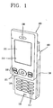
- Figure 1 is a perspective view illustrating a top sliding type mobile terminal.
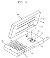
- Figure 2 is an exploded view illustrating the top sliding type mobile terminal.
- Figure 3 is a perspective view illustrating operation of the top sliding type mobile terminal.
- the mobile terminal includes a body 100 having a lower portion that includes a keypad 110.
- the mobile terminal also includes a slider 200 configured to slidingly couple to the body 100.
- the mobile terminal also includes a longitudinal sliding unit coupled between the slider 200 and the body 100 such that the slider 200 may move longitudinally with respect to the body 100.
- the mobile terminal also includes a display unit 210 fixedly coupled to the slider 200.
- the body 100 may be constructed in a rectangle shape and have a certain thickness.
- a keypad 110 has a plurality of keys 111 and is placed in the body 100 such that the keys 111 may protrude outside of the body 100.
- the number of the keys 111 may be decreased because of limitations on the size of the area where the keys 111 are arranged. Therefore, each of the keys 111 may have both a function of entering numbers and a function of entering letters. That is, the primary function of the keys 111 is to enter numbers, but each of the keys 111 may also be used to enter a plurality of letters. Therefore, to input a message, the same key 111 may need to be pressed several times to input different letters.
- the slider 200 When in a first position, the slider 200 is placed on top of the body 100 such that the keys 111 are covered by the slider 200. When the slider 200 is moved in a longitudinal direction with respect to the body 100, the keys 111 are exposed to provide access to the keys 111 for a user. Furthermore, a battery 120 is detachably mounted on the lower surface of the body 100.
- a display unit 210 is provided on an outer surface of the slider 200.
- An operating keypad 220 is provided on the outer surface of the slider 200, below the display unit. Voice phone calls are made and terminated by pressing keys 221 on the operating keypad 220.
- a display window 211 of the display unit 210 is rectangular in shape and is oriented in the same longitudinal direction as the slider 200.
- the longitudinal sliding unit is provided on an inner surface of the body 100 and an inner surface of the slider 200.
- the longitudinal sliding unit includes a driving motor 310 provided in the body 100, a pinion 320 coupled to the driving motor 310, and a rack 330 mounted longitudinally on the inner surface of the slider 200 and having one side engaged with the pinion 320.
- Reference numerals 201, 101, 230 and 130 represent guide grooves, guide protrusions inserted into the guide grooves, a receiver and a microphone, respectively.
- a semi-automatic closing technique may be implemented in the mobile terminal using a wire spring.
- the amount of space required for the slider 200 to move is minimal, allowing for the mobile terminal to have increased structural strength.
- the amount of space required for the folder to move is increased because the folder needs to be opened and closed on an axis located at one end of the body. Furthermore, the structural strength of the folding mobile terminal is weakened when the folder is opened.
- the area on the body 100 that may be used for the keypad 110 is limited. Therefore, a small number of keys 111 are included in the keypad 110, necessitating that multiple functions must be assigned to each key 111. Furthermore, if letters are inputted using the keys 111, each key 111 must be pressed two or three times for each letter to be input. The above drawbacks may make the top sliding type mobile terminal inconvenient for sending and receiving text messages.
- a mobile terminal of the sliding type which permits sliding a slider in a transverse direction with respect to a body.
- Letter and number keys are all arranged on the body such that the slider, when slid over the body, covers only the letter keys.
- the present invention is directed to a side sliding type mobile terminal that substantially obviates one or more problems due to limitations and disadvantages of the related art.
- An object of the present invention is to provide a side sliding type mobile terminal capable of including an expanded keypad to simplify letter input by utilizing a wider area to increase the number of letter keys available to a user without sacrificing user-friendless.
- a mobile terminal comprises the features set out in claim 1.
- the slider comprises a display unit configured to display image information.
- the slider is configured to slide into a first position and a second position.
- the keypad is covered by the slider when the slider is slid into the first position and the keypad is exposed when the slider is slid into the second position.
- the slider comprises a display unit configured to display image information.
- the mobile terminal may further comprise a processor coupled to the slider, configured to detect when the slider is slid from the first position to the second position and when the slider is slid from the second position to the first position.
- the image information may be rotated 90 degrees from a transverse orientation to a longitudinal orientation when the processor detects that the slider has been slid from the first position to the second position.
- the image information may be rotated 90 degrees from a longitudinal orientation to a transverse orientation when the processor detects that the slider has been slid from the second position to the first position.
- the slider may further comprise a number keypad for numerical input and an operational keypad for performance of call functions.
- the keypad may comprise letter keys and symbol keys, and may have a QWERTY key layout, for example.
- Figure 4 is a front view illustrating a side sliding type mobile terminal, according to one embodiment of the present invention.
- Figures 5 and 6 are a front view and a rear view, respectively, illustrating a side sliding type mobile terminal in an opened configuration, according to one embodiment of the present invention.
- a side sliding type mobile terminal (mobile terminal) 505 includes a body 400.
- the mobile terminal 505 also includes a slider 500 configured to slidingly couple to the body 400.
- the length and the width of the body 400 may be different from each other.
- the length and the width of the slider 500 may be different from each other.
- the mobile terminal 505 also includes a transverse sliding unit 600 mounted between the body 400 and the slider 500 such that the slider 500 may move (e.g., slide) transversely with respect to the body 400.
- the body 400 may be constructed with a rectangular shape and may have a predetermined thickness, for example.
- the width of the body 400 may be smaller than the length of the body 400.
- Inner surfaces of the body 400 and the slider 500, respectively, are the surfaces that are mounted to the transverse sliding unit 600.
- Outer surfaces of the body 400 and the slider 500, respectively, are the surfaces opposite the inner surfaces of the body 400 and the slider 500.
- the inner surface of the body 400 may be divided into two sections, a first section being a key arrangement region, where a keypad 410 is located, and a second section being a mounting region for coupling with the transverse sliding unit 600.
- the keypad may preferably include a QWERTY keypad layout.
- the slider 500 may also be constructed with a rectangular shape and may have a predetermined thickness, for example.
- the inner surfaces of the body 400 and the slider 500 may have the same size and shape.
- a printed circuit board (PCB) or the like may be mounted within the slider 500.
- a number keypad 510 may be provided on the outer surface of the slider 500.
- Operating keys 520 may also be provided on the outer surface of the slider 500, such as for example, above the number keypad 510.
- a display unit 530 may be provided on the outer surface of the slider 500, such as for example, above the operating keys 520.
- a display window 531 may be formed in the display unit 530. The display window 531 may have a rectangular shape, with a width different from a length, for example.
- Figures 7 and 8 are an exploded perspective view and a cross-section view, respectively, illustrating a transverse sliding unit used in a side sliding type mobile terminal, according to the present invention.
- the transverse sliding unit 600 includes a rail body 610 coupled to the slider 500.
- the transverse sliding unit 600 also includes a rail guide 620 slidably coupled to the rail body 610 and fixedly coupled to the body 400.
- the transverse sliding unit 600 also includes a detachment unit such that the rail guide 620 may be detached from the rail body 610 at a set position of the rail body 610.
- the rail body 610 may include a base portion 611 coupled to the inside surface of the slider 500.
- the base portion 611 may be constructed with a rectangular shape and may have a predetermined thickness, for example.
- a rail groove 612 may be formed longitudinally in the base portion 611.
- the rail groove 612 may include a longitudinal groove portion 613 and transverse groove portions 614.
- the longitudinal groove portion 613 may have a specified width and depth and the transverse groove portions 614 may be constructed with a square shape at both sides of the surface of the longitudinal groove portion 613 closest to the slider.
- the rail body 610 may be fixedly coupled to the inner surface of the slider 500 such that the longitudinal dimension of the rail body 610 coincides with the transverse dimension of the slider 500.
- the rail body 610 may be coupled to the slider 500 by a fastener, such as for example, a screw.
- the rail guide 620 may include a rail portion 621 slidably coupled to the rail groove 612 and stopping portions 622 extending from both sides of the rail portion 621.
- the rail portion 621 may be constructed with a hexahedron shape and may have a width corresponding to the width of the rail groove 612, for example.
- a protrusion 623 may be formed at an upper surface of the hexahedron shaped rail portion 621.
- the stopping portions 622 may be constructed with a predetermined thickness and length at edges of the rail portion 621.
- the rail guide 620 may be coupled to the mounting region on the inner surface of the body 400 such that the longitudinal dimension of the rail guide 620 coincides with the transverse dimension of the body 400.
- the rail guide 620 may be coupled to the body 400 by a fastener, such as for example, a screw.
- the rail portion 621 and the stopping portions 622 may be inserted into the rail groove 612 to couple the rail guide 620 to the rail body 610.
- the detachment unit may include detachment grooves 615 formed in the rail groove 612.
- the detachment unit may also include an elastic detachment protrusion 624 formed on the rail portion 621 of the rail guide 620 and configured to be detached from the detachment grooves 615 by the elasticity of the elastic detachment protrusion 624.
- Two detachment grooves 615 may be formed at certain intervals of the rail groove 612.
- the elastic detachment groove 624 may preferably be protrudingly formed at or near the center of the surface of the rail portion 621 away from the body 400.
- a first detachment groove 615 may be located at half a length of the rail guide 620 from an end of the rail body 610, for example.
- a second detachment groove 615 may be located at half a length of the rail body 610 from an end of the rail guide 620, for example.
- two transverse sliding units 600 may be disposed at certain intervals of the slider 500.
- a buffering member 630 configured to smooth the sliding of the slider 500 with respect to the body 400 may be provided between the slider 500 and the body 400.
- the buffering member 630 may be constructed from lubrication-coated synthetic rubber wires, for example.
- Two buffering members 630 may be disposed at certain intervals of the slider 500, for example.
- a receiver 540 and a microphone 550 may be mounted on the outer surface of the slider 500.
- the receiver 540 may be mounted at an upper portion of the slider 500, for example, and the microphone 550 may be mounted on a lower portion of the slider 500, for example.
- a battery 420 and a speaker 430 may be detachably mounted to the outer surface of the body 400, for example.
- Figure 9 is a flow diagram illustrating a method for controlling a side sliding type mobile terminal, according to one embodiment of the present invention.
- the method of controlling the side sliding type mobile terminal comprises, at step 910, moving the slider 500, including the display unit 530, transversely with respect to the body 400.
- image information is displayed on the display unit 530, the display unit 530 turning 90 degrees upon detecting the movement of the slider 500.
- the body 400 and the slider 500 each have a length (longitudinal dimension) and a width (transverse dimension).
- the respective lengths of the body 400 and the slider 500 are longer than the respective widths of the body 400 and the slider 500. Longitudinal and transverse orientations are viewed with respect to lengths and widths of the body 400 and the slider 500.
- the slider 500 may preferably be slid transversely with respect to the body 400.
- Figures 10 and 11 are front views illustrating a side sliding type mobile terminal, according to one embodiment of the present invention.
- image information may be displayed transversely with respect to the body 400.
- the image information may be displayed longitudinally with respect to the body 400.
- the mobile terminal is used to make a voice call.
- the user inputs the telephone number of the receiving party by pressing the number keys 510 provided on the slider 500 and executes the call by pressing the operating keys 520.
- the user may end the call by pressing the operating keys 520.
- the user may answer an incoming call by pressing the operating keys 520.
- the user may end the call by pressing the operating keys 520.
- image information may be displayed transversely on the display unit 530 to enable convenient viewing by the user.
- the slider 500 may be positioned on top of the body 400.
- the mobile terminal is used for text based communication, such as for example, text messaging or Internet usage.
- the user may slide the slider 500 in a transverse direction with respect to the body 400, so that the letter keys 410 provided on the body 400 are exposed.
- the rail body 610 coupled to the slider 500 and the rail guide 620 coupled to the body 400 may slide with respect to each other. If the slider 500 is slid a certain distance with respect to the body 400, the elastic protrusion 624 of the rail guide 620 coupled to the slider 500 may insert into and fix the detachment groove 615 of the rail body 610, so that the slider 500 becomes fixed in place.
- the transverse movement of the slider 500 may be detected by a processor within the mobile terminal. When the transverse movement of the slider 500 is detected, the image information displayed on the display unit 530 may be rotated 90 degrees, for example.
- the user may rotate the mobile terminal 90 degrees such that the mobile terminal 'faces' the user for convenient text input. That is, the mobile terminal may be oriented such that the letter keys 410 are positioned to face the user, the display unit 530 is positioned above the letter keys 410, and the image information is displayed longitudinally on the display unit 530. The user may then input letters and/or symbols using the letter keys 410 provided on the body 400.
- the user may slide the slider 500 transversely with respect to the body 400 so that the slider 500 retracts and fits on top of the body 400.
- the elastic protrusion 624 may separate from the detachment groove 615 and be inserted into a different detachment groove 615 to fix the slider 500 in position on top of the body 400.
- the image information displayed on the display unit 530 may rotate 90 degrees so that the image information is displayed transversely.
- a mobile terminal comprises a body comprising a keypad and a slider slidingly coupled to the body.
- the slider is configured to slide transversely with respect to the body and may comprise a display unit configured to display image information.
- the keypad may comprise keys arranged longitudinally with respect to the body.
- the slider may be configured to slide into a first position and a second position.
- the keypad may be covered by the slider when the slider is slid into the first position and the keypad may be exposed when the slider is slid into the second position.
- the slider may comprise a display unit configured to display image information.
- the mobile terminal may further comprise a processor coupled to the slider, configured to detect when the slider is slid from the first position to the second position and when the slider is slid from the second position to the first position.
- the image information may be rotated 90 degrees from a transverse orientation to a longitudinal orientation when the processor detects that the slider has been slid from the first position to the second position.
- the image information may be rotated 90 degrees from a longitudinal orientation to a transverse orientation when the processor detects that the slider has been slid from the second position to the first position.
- the slider may further comprise a number keypad for numerical input and an operational keypad for performance of call functions.
- the keypad may comprise letter keys and symbol keys, and may have a QWERTY key layout, for example.
- a mobile terminal in another embodiment, comprises a body having a length (longitudinal dimension) different from a width (transverse dimension), the body comprising a keypad having keys.
- the mobile terminal also comprises a transverse sliding unit coupled to the body and a slider, configured to enable the slider to slide transversely with respect to the body.
- the mobile terminal also comprises the slider coupled to the transverse sliding unit.
- the keypad may be positioned on top of the body when the slider is in the first position.
- the slider may have the same width and length as the body on the surfaces of the slider and the body that couple to the transverse sliding unit, respectively.
- the transverse sliding unit may comprise a rail body coupled to the body or the slider, and a rail guide slidably coupled to the rail body and fixedly coupled to the body or the slider.
- the transverse sliding unit may further comprise a detachment unit configured to enable the rail guide to be detached from the rail body at a set position of the rail body.
- the detachment unit may comprise detachment grooves in the rail body, and an elastic detachment protrusion in the rail guide configured to couple with the detachment grooves.
- the rail body may comprise a base portion constructed with a rectangular shape and a predetermined thickness, and a rail groove formed longitudinally on a surface of the base portion.
- the rail guide may comprise a rail portion slidably coupled to the rail groove of the rail body, and stopping portions extending from both sides of the rail portion.
- the side sliding type mobile terminal may further comprise a buffering member coupled to the slider or the body, configured to buffer relative motion between the slider and the body.
- a method of controlling a mobile terminal comprises transversely sliding a slider with respect to a body and detecting the sliding of the slider with respect to the body.
- the method also comprises rotating image information on a display unit of the slider to enable viewing of the image information by a user in response to the detecting of the sliding of the slider with respect to the body.
- the sliding of the slider may expose a keypad on the body to enable the user to perform text based communication. Conversely, the sliding of the slider may place the slider in a position on top of the body to enable the user to perform voice based communication.
- the size of the mobile terminal may effectively decrease, allowing for greater portability. Furthermore, due to the side sliding type construction of the mobile terminal, the available area for arrangement of a letter keypad is increased. Additionally, since more area is available for a letter keypad, a key arrangement with a greater number of keys, such as for example, a QWERTY keypad may be included in the mobile terminal. Therefore, it may not be necessary to assign multiple functions to each key or to press a key several times to input a single letter.
- the image information display may be rotated 90 degrees in response to sliding of the slider, the image information may be conveniently viewed by the user, regardless of whether the mobile terminal is being used for a voice call or text based communication.
- the present invention may enable convenient text based communication while still providing a bar type mobile terminal for voice calls.
Claims (10)
- Mobiles Endgerät (505), mit:- einem Gehäusekörper (400) mit unterschiedlicher Länge und Breite und mit einer darauf befindlichen Tastatur (410), wobei die Tastatur (410) auf dem Gehäusekörper (400) angeordnete Buchstabentasten und/oder Symboltasten aufweist,- einem Schieber (500), der dieselbe Breite und Länge hat wie der Gehäusekörper (400) und an einer Außenfläche des Schiebers (500) eine Anzeigeeinheit (530) zum Ermöglichen einer Anzeige von Bildinformationen, einen Empfänger (540) und/oder ein Mikrofon (550) sowie eine Zahlentastatur (510) und Bedienungstasten (520) aufweist,- einer Querverschiebeeinheit (600), die zwischen dem Gehäusekörper (400) und dem Schieber (500) angeordnet ist und den Gehäusekörper (400) mit dem Schieber (500) koppelt, um es dem Schieber (500) zu ermöglichen, bezüglich des Gehäusekörpers (400) in eine Breitenrichtung zu gleiten, wobei die Querverschiebeeinheit (600) umfasst:-- einen Schienenkörper (610), der mit dem Gehäusekörper (400) oder dem Schieber (500) gekoppelt ist, und-- eine Schienenführung (620), die verschiebbar mit dem Schienenkörper (610) und fest mit dem Gehäusekörper (400) oder dem Schieber (500) gekoppelt ist,- wobei eine Innenfläche des Gehäusekörpers (400) einen ersten Abschnitt, in dem sich die Tastatur (410) befindet, und einen zweiten Abschnitt umfasst, in dem sich der Schienenkörper (610) oder die Schienenführung (620) befindet, und wobei ferner- der Schieber (500) zwischen einer ersten Stellung, in der der Schieber (500) den ersten Abschnitt abdeckt, und einer zweiten Stellung bewegbar ist, in der der erste Abschnitt freiliegt, so dass die Tastatur (410) durch den Schieber (500) abgedeckt ist, wenn sich der Schieber (500) in der ersten Stellung befindet, und die Tastatur (410) freiliegt und der Schienenkörper (610) oder die Schienenführung (620) durch den Schieber (500) abgedeckt ist, wenn sich der Schieber (500) in der zweiten Stellung befindet.
- Mobiles Endgerät (505) nach Anspruch 1,
das ferner einen mit dem Schieber (500) gekoppelten Prozessor umfasst, der dazu ausgeführt ist, zu ermitteln, ob der Schieber (500) aus der ersten Stellung in die zweite Stellung geschoben wird, und ob der Schieber (500) aus der zweiten Stellung in die erste Stellung geschoben wird. - Mobiles Endgerät (505) nach Anspruch 2,
bei dem die Bildinformationen bezüglich des Gehäusekörpers (400) um 90 Grad aus der Breitenrichtung in die Längenrichtung gedreht und angezeigt werden, wenn der Prozessor ermittelt, dass der Schieber (500) aus der ersten Stellung in die zweite Stellung geschoben worden ist. - Mobiles Endgerät (505) nach Anspruch 2,
bei dem die Bildinformationen bezüglich des Gehäusekörpers (400) um 90 Grad aus der Längenrichtung in die Breitenrichtung gedreht und angezeigt werden, wenn der Prozessor ermittelt, dass der Schieber (500) aus der zweiten Stellung in die erste Stellung geschoben worden ist. - Mobiles Endgerät (505) nach Anspruch 1,
bei dem die Tastatur (410) eine QWERTY-Tastenanordnung aufweist. - Mobiles Endgerät (505) nach Anspruch 1,
bei dem die Querverschiebeeinheit (600) ferner eine Trenneinheit umfasst, die dafür ausgestaltet ist, an einer festgelegten Position des Schienenkörpers (610) ein Abnehmen der Schienenführung (620) vom Schienenkörper (610) zu ermöglichen. - Mobiles Endgerät (505) nach Anspruch 6,
bei dem die Trenneinheit umfasst:- Entnahmenuten (615) im Schienenkörper (610), und- einen elastischen Entnahmevorsprung (624) in der Schienenführung (620), der dafür ausgestaltet ist, mit den Entnahmenuten (615) gekoppelt zu werden. - Mobiles Endgerät (505) nach Anspruch 1,
bei dem der Schienenkörper (610) umfasst:- einen Basisabschnitt (611), der mit einer rechteckigen Form und einer vorgegebenen Dicke ausgeführt ist, und- eine Schienennut (612), die auf einer Oberfläche des Basisabschnitts (611) in einer Längenrichtung der Basis ausgebildet ist. - Mobiles Endgerät (505) nach Anspruch 1,
bei dem die Schienenführung (620) umfasst:- einen Schienenabschnitt (621), der verschiebbar mit der Schienennut (612) des Schienenkörpers (610) gekoppelt ist, und- Anschlagabschnitte, die sich von beiden Seiten des Schienenabschnitts (621) erstrecken. - Mobiles Endgerät (505) nach Anspruch 1,
das ferner ein Dämpferelement (630) umfasst, das mit dem Schieber (500) oder dem Gehäusekörper (400) gekoppelt und dazu ausgeführt ist, eine Relativbewegung zwischen dem Schieber (500) und dem Gehäusekörper (400) zu dämpfen.
Applications Claiming Priority (1)
| Application Number | Priority Date | Filing Date | Title |
|---|---|---|---|
| KR1020040110676A KR100721337B1 (ko) | 2004-12-22 | 2004-12-22 | 사이드 슬라이딩형 전자장치 |
Publications (2)
| Publication Number | Publication Date |
|---|---|
| EP1675359A1 EP1675359A1 (de) | 2006-06-28 |
| EP1675359B1 true EP1675359B1 (de) | 2012-10-31 |
Family
ID=36061530
Family Applications (1)
| Application Number | Title | Priority Date | Filing Date |
|---|---|---|---|
| EP05019452A Not-in-force EP1675359B1 (de) | 2004-12-22 | 2005-09-07 | Mobiles endgerät mit einem quer verschiebbaren, eine anzeigevorrichtung umfassenden, gehäuseteil |
Country Status (6)
| Country | Link |
|---|---|
| US (2) | US7610069B2 (de) |
| EP (1) | EP1675359B1 (de) |
| JP (1) | JP2006178924A (de) |
| KR (1) | KR100721337B1 (de) |
| CN (2) | CN100531236C (de) |
| DE (1) | DE202005021699U1 (de) |
Families Citing this family (51)
| Publication number | Priority date | Publication date | Assignee | Title |
|---|---|---|---|---|
| KR100704031B1 (ko) * | 2004-04-29 | 2007-04-04 | 삼성전자주식회사 | 이중 슬라이딩 타입 휴대용 통신 장치 |
| KR100616197B1 (ko) | 2004-08-24 | 2006-08-25 | 삼성전자주식회사 | 이중 슬라이딩 타입 휴대용 통신 장치의 슬라이딩 장치 |
| KR100721337B1 (ko) * | 2004-12-22 | 2007-05-28 | 엘지전자 주식회사 | 사이드 슬라이딩형 전자장치 |
| JP4568332B2 (ja) * | 2005-09-20 | 2010-10-27 | スガツネ工業株式会社 | 携帯機器 |
| WO2007060730A1 (ja) * | 2005-11-25 | 2007-05-31 | Mitsubishi Denki Kabushiki Kaisha | 携帯端末 |
| KR100845862B1 (ko) * | 2006-04-25 | 2008-07-14 | 엘지전자 주식회사 | 이동 단말기 |
| CN101102652A (zh) * | 2006-07-07 | 2008-01-09 | 深圳富泰宏精密工业有限公司 | 滑盖结构及应用该滑盖结构的便携式电子装置 |
| EP1887761A3 (de) * | 2006-08-08 | 2012-12-26 | Samsung Electronics Co., Ltd. | Mobile Kommunikationsvorrichtung mit einem eine Qwerty-Tastatur überdeckenden schieb- und drehbarem Gehäuse |
| EP1895382A1 (de) | 2006-08-28 | 2008-03-05 | Research In Motion Limited | Tastaturlayout mit in drei Reihen angeordneten Tasten für ein kompaktes mobiles Kommunikationsgerät |
| EP1895381A1 (de) * | 2006-08-28 | 2008-03-05 | Research In Motion Limited | Tragbare Vorrichtung mit hybridem Hoch- und Querformat, Rollkugel-Navigation und verborgener Qwerty-Tastatur |
| JP2008076818A (ja) * | 2006-09-22 | 2008-04-03 | Fujitsu Ltd | 携帯端末装置 |
| TW200825869A (en) * | 2006-12-13 | 2008-06-16 | Kye Systems Corp | Computer input device |
| US8131902B2 (en) * | 2007-03-06 | 2012-03-06 | International Business Machines Corporation | Determining orientation of blade server inserted into a blade chassis |
| JP4450008B2 (ja) | 2007-04-17 | 2010-04-14 | 株式会社カシオ日立モバイルコミュニケーションズ | 電子機器 |
| EP1988691B1 (de) * | 2007-05-02 | 2014-03-05 | Samsung Electronics Co., Ltd. | Tragbares Endgerät mit Schiebemechanismus |
| JP2009003614A (ja) * | 2007-06-20 | 2009-01-08 | Sony Corp | スライド機構及び電子機器 |
| TWI351209B (en) * | 2007-07-25 | 2011-10-21 | High Tech Comp Corp | Electronic apparatus and flexible printed circuit board thereof |
| US8121659B2 (en) | 2007-12-20 | 2012-02-21 | Nokia Corporation | Slide mechanism |
| US20090256861A1 (en) * | 2007-12-31 | 2009-10-15 | Motorola, Inc. | Device and Method for Managing the Orientation of Information Being Displayed on the Screen of a Device |
| US8217964B2 (en) * | 2008-02-14 | 2012-07-10 | Nokia Corporation | Information presentation based on display screen orientation |
| JP2009278411A (ja) * | 2008-05-15 | 2009-11-26 | Sony Ericsson Mobilecommunications Japan Inc | 携帯装置 |
| JP2009284018A (ja) | 2008-05-19 | 2009-12-03 | Fujitsu Ltd | 情報端末 |
| EP2128660B1 (de) * | 2008-05-28 | 2012-04-18 | Lighting Science Group Corporation | Leuchte und Betriebsverfahren |
| US7953462B2 (en) | 2008-08-04 | 2011-05-31 | Vartanian Harry | Apparatus and method for providing an adaptively responsive flexible display device |
| KR101035126B1 (ko) * | 2008-08-07 | 2011-05-19 | 주식회사 한빛티앤아이 | 자판 내장형 휴대폰용 슬라이드 힌지 모듈 |
| EP2151975A1 (de) | 2008-08-07 | 2010-02-10 | Hanbit Precision Co., Ltd. | Schiebegelenkmodul für ein Mobiltelefon |
| US20100066640A1 (en) * | 2008-09-12 | 2010-03-18 | Sony Ericsson Mobile Communications Ab | Electronic Device with Locking, Movable Displays |
| JP2010093555A (ja) * | 2008-10-08 | 2010-04-22 | Sharp Corp | 通信装置、操作キー表示制御方法、及び操作キー表示制御プログラム |
| US20120106077A1 (en) * | 2008-10-31 | 2012-05-03 | Tracy Mark S | Extruding Material Through A Die To Produce A Computer Chassis |
| KR101019679B1 (ko) * | 2008-11-17 | 2011-03-07 | 주식회사 한빛티앤아이 | 휴대폰용 슬라이드 힌지 모듈 |
| CN101754621A (zh) * | 2008-11-28 | 2010-06-23 | 深圳富泰宏精密工业有限公司 | 滑盖式电子装置 |
| US8463326B2 (en) * | 2009-02-23 | 2013-06-11 | Research In Motion Limited | Handheld electronic device transitionable between different configurations |
| US8103322B2 (en) * | 2009-02-27 | 2012-01-24 | Research In Motion Limited | Handheld electronic device having two device members slidable relative to a bridge |
| US8023975B2 (en) * | 2009-03-23 | 2011-09-20 | T-Mobile Usa, Inc. | Secondary status display for mobile device |
| US8224407B2 (en) * | 2009-03-23 | 2012-07-17 | T-Mobile Usa, Inc. | Mobile device having a movable display and associated systems and methods |
| US8391935B2 (en) * | 2009-03-23 | 2013-03-05 | T-Mobile Usa, Inc. | Multifunction mobile device having a movable element, such as a display, and associated functions |
| US20100299874A1 (en) * | 2009-05-27 | 2010-12-02 | Ming-Han Lin | Sliding Hinge |
| KR101578430B1 (ko) * | 2009-07-13 | 2015-12-18 | 엘지전자 주식회사 | 이동 단말기 |
| CN101989170A (zh) * | 2009-07-29 | 2011-03-23 | 深圳富泰宏精密工业有限公司 | 便携式电子装置 |
| JP5330934B2 (ja) | 2009-08-27 | 2013-10-30 | 京セラ株式会社 | 携帯電子機器及び携帯電子機器の表示方法 |
| KR101602229B1 (ko) * | 2009-09-25 | 2016-03-10 | 엘지전자 주식회사 | 이동 단말기 |
| US9436219B2 (en) | 2010-05-12 | 2016-09-06 | Litl Llc | Remote control to operate computer system |
| US8938753B2 (en) | 2010-05-12 | 2015-01-20 | Litl Llc | Configurable computer system |
| JP5384430B2 (ja) * | 2010-05-31 | 2014-01-08 | 株式会社Nttドコモ | スライド式移動機構及び電子機器 |
| GB2485534B (en) * | 2010-11-15 | 2016-08-17 | Edesix Ltd | Imaging recording apparatus |
| US10474409B2 (en) * | 2014-09-19 | 2019-11-12 | Lenovo (Beijing) Co., Ltd. | Response control method and electronic device |
| US11347367B2 (en) | 2019-01-18 | 2022-05-31 | Dell Products L.P. | Information handling system see do user interface management |
| US11169653B2 (en) | 2019-01-18 | 2021-11-09 | Dell Products L.P. | Asymmetric information handling system user interface management |
| US11009907B2 (en) | 2019-01-18 | 2021-05-18 | Dell Products L.P. | Portable information handling system user interface selection based on keyboard configuration |
| WO2022019357A1 (ko) | 2020-07-24 | 2022-01-27 | 엘지전자 주식회사 | 이동 단말기 |
| KR20220166839A (ko) | 2020-07-24 | 2022-12-19 | 엘지전자 주식회사 | 이동 단말기 |
Citations (2)
| Publication number | Priority date | Publication date | Assignee | Title |
|---|---|---|---|---|
| US20010048589A1 (en) * | 1999-12-20 | 2001-12-06 | Brandenberg Carl Brock | Physical configuration of a hand-held electronic communication device |
| DE20317865U1 (de) * | 2003-11-06 | 2004-03-04 | Inventec Appliances Corporation, Wu-Ku | Tragbares elektronisches Kommunikationsgerät mit zwei verschiebbaren Tastaturen |
Family Cites Families (36)
| Publication number | Priority date | Publication date | Assignee | Title |
|---|---|---|---|---|
| US6243595B1 (en) * | 1998-06-16 | 2001-06-05 | Nortel Networks Limited | Portable wireless communication device having an extendible section |
| US6483445B1 (en) * | 1998-12-21 | 2002-11-19 | Intel Corporation | Electronic device with hidden keyboard |
| US6437973B1 (en) * | 2000-04-18 | 2002-08-20 | Hewlett-Packard Company | Modular mechanism for movable display |
| JP3964607B2 (ja) | 2000-08-08 | 2007-08-22 | アルプス電気株式会社 | 携帯型情報端末 |
| DE60119681T2 (de) * | 2000-12-28 | 2007-05-10 | Cellon France S.A.S. | Elektronische Vorrichtung mit zwei zueinander beweglichen Teilen |
| KR100470172B1 (ko) | 2001-06-22 | 2005-02-04 | 주식회사 임팩트라 | 디스플레이부를 수직 및 수평으로 변환가능한 이동단말기 |
| US6636419B2 (en) * | 2001-08-09 | 2003-10-21 | Danger, Inc. | Handheld display and keyboard |
| JP2003125053A (ja) * | 2001-10-18 | 2003-04-25 | Bosu & K Consulting Kk | 携帯電話 |
| US6850226B2 (en) * | 2001-11-09 | 2005-02-01 | Nokia Corporation | Multifunction mobile communications device with slidable display screen |
| JP2003288154A (ja) * | 2002-03-27 | 2003-10-10 | Casio Comput Co Ltd | 電子機器 |
| JP2003319042A (ja) * | 2002-04-25 | 2003-11-07 | Matsushita Electric Ind Co Ltd | 携帯端末機器 |
| JP3910112B2 (ja) * | 2002-06-21 | 2007-04-25 | シャープ株式会社 | カメラ付携帯電話機 |
| US6847310B1 (en) * | 2002-06-21 | 2005-01-25 | Bsquare Corporation | Keyboard |
| US7305631B1 (en) * | 2002-09-30 | 2007-12-04 | Danger, Inc. | Integrated motion sensor for a data processing device |
| US6829139B1 (en) * | 2002-10-01 | 2004-12-07 | Danger, Inc. | Adjustable data processing display |
| AU2003291132A1 (en) * | 2002-11-21 | 2004-06-18 | Danger, Inc. | Data processing device with adjuntable display and input devices with multiple orientations |
| US7277275B2 (en) * | 2003-04-09 | 2007-10-02 | Samsung Electronics Co., Ltd. | Portable computer having adjustable display |
| KR20040102680A (ko) | 2003-05-29 | 2004-12-08 | 하경균 | 슬라이딩 타입 휴대폰의 슬라이드 트랙 |
| US7529571B2 (en) * | 2003-09-03 | 2009-05-05 | Samsung Electronics Co., Ltd. | Sliding/hinge apparatus for sliding/rotating type mobile terminals |
| JP2005084955A (ja) * | 2003-09-09 | 2005-03-31 | Hitachi Ltd | 携帯情報端末 |
| KR100563696B1 (ko) * | 2003-09-09 | 2006-03-28 | 엘지전자 주식회사 | 슬라이드형 이동통신 단말기의 슬라이드 구조 |
| US7107018B2 (en) * | 2003-09-12 | 2006-09-12 | Motorola, Inc. | Communication device having multiple keypads |
| KR100703339B1 (ko) * | 2003-09-24 | 2007-04-03 | 삼성전자주식회사 | 슬라이딩 타입 휴대용 무선 단말기 및 이 무선단말기에서의 슬라이딩 제어 방법 |
| US20050070348A1 (en) * | 2003-09-29 | 2005-03-31 | Inventec Appliances Corp. | Hand-held communication electronic apparatus having two slidable keypads |
| KR100617690B1 (ko) * | 2003-11-10 | 2006-08-28 | 삼성전자주식회사 | 슬라이딩 타입 휴대용 무선 단말기 |
| US7042711B2 (en) * | 2003-11-18 | 2006-05-09 | Kabushiki Kaisha Toshiba | Multi-functional electronic device with a continuously accessible pointing device |
| US7092246B2 (en) * | 2003-11-18 | 2006-08-15 | Kabushiki Kaisha Toshiba | Apparatus for connecting a display to a body case of an electronic device |
| KR100532334B1 (ko) * | 2003-11-26 | 2005-11-29 | 삼성전자주식회사 | 슬라이딩 겸용 폴딩 타입 휴대용 디지털 통신 장치 |
| KR100608726B1 (ko) * | 2003-12-09 | 2006-08-04 | 엘지전자 주식회사 | 양방향 슬라이드형 휴대용 단말기 |
| KR100655114B1 (ko) * | 2004-03-26 | 2006-12-08 | 이근주 | 슬라이드형 휴대폰용 모듈 |
| US7262761B1 (en) * | 2004-04-21 | 2007-08-28 | Danger, Inc. | User interface for detecting a data entry mode |
| KR20070036802A (ko) * | 2004-09-14 | 2007-04-03 | 미쓰비시덴키 가부시키가이샤 | 휴대 기기 |
| US20060109980A1 (en) * | 2004-11-19 | 2006-05-25 | Yuichi Miyazaki | Portable wireless communication device |
| US7353053B2 (en) * | 2004-11-23 | 2008-04-01 | Oqo, Inc. | Non-binding sliding display for a handheld electronic device |
| WO2006067259A1 (en) * | 2004-12-20 | 2006-06-29 | Nokia Corporation | Electronic device |
| KR100721337B1 (ko) * | 2004-12-22 | 2007-05-28 | 엘지전자 주식회사 | 사이드 슬라이딩형 전자장치 |
-
2004
- 2004-12-22 KR KR1020040110676A patent/KR100721337B1/ko not_active IP Right Cessation
-
2005
- 2005-09-07 DE DE202005021699U patent/DE202005021699U1/de not_active Expired - Lifetime
- 2005-09-07 EP EP05019452A patent/EP1675359B1/de not_active Not-in-force
- 2005-09-13 JP JP2005266120A patent/JP2006178924A/ja active Pending
- 2005-09-15 US US11/228,740 patent/US7610069B2/en not_active Expired - Fee Related
- 2005-12-20 CN CNB2005101339184A patent/CN100531236C/zh not_active Expired - Fee Related
- 2005-12-20 CN CN2009101335158A patent/CN101540791B/zh not_active Expired - Fee Related
-
2009
- 2009-09-15 US US12/560,343 patent/US8938276B2/en not_active Expired - Fee Related
Patent Citations (2)
| Publication number | Priority date | Publication date | Assignee | Title |
|---|---|---|---|---|
| US20010048589A1 (en) * | 1999-12-20 | 2001-12-06 | Brandenberg Carl Brock | Physical configuration of a hand-held electronic communication device |
| DE20317865U1 (de) * | 2003-11-06 | 2004-03-04 | Inventec Appliances Corporation, Wu-Ku | Tragbares elektronisches Kommunikationsgerät mit zwei verschiebbaren Tastaturen |
Also Published As
| Publication number | Publication date |
|---|---|
| KR100721337B1 (ko) | 2007-05-28 |
| KR20060071706A (ko) | 2006-06-27 |
| US8938276B2 (en) | 2015-01-20 |
| CN101540791A (zh) | 2009-09-23 |
| DE202005021699U1 (de) | 2009-06-04 |
| CN1794752A (zh) | 2006-06-28 |
| JP2006178924A (ja) | 2006-07-06 |
| CN101540791B (zh) | 2012-02-29 |
| US7610069B2 (en) | 2009-10-27 |
| US20060135229A1 (en) | 2006-06-22 |
| US20100004038A1 (en) | 2010-01-07 |
| EP1675359A1 (de) | 2006-06-28 |
| CN100531236C (zh) | 2009-08-19 |
Similar Documents
| Publication | Publication Date | Title |
|---|---|---|
| EP1675359B1 (de) | Mobiles endgerät mit einem quer verschiebbaren, eine anzeigevorrichtung umfassenden, gehäuseteil | |
| EP1804468B1 (de) | Tragbares Endgerät, das zwei Tastaturen hat | |
| US6495784B2 (en) | Step keys, step key assembly, and terminal having the step key assembly | |
| EP1720326B1 (de) | Tragbares Endgerät mit zwei Gehäusen die sowohl faltbar als auch ausziehbar relativ zueinander sind | |
| US8155718B2 (en) | Sliding/hinge apparatus for sliding/rotating type mobile terminals | |
| US7620425B2 (en) | Mobile terminal having a plurality of displays | |
| US7697270B2 (en) | Portable electronic device | |
| JP3959086B2 (ja) | 移動通信端末機用スライダーアセンブリ | |
| CN102420883B (zh) | 便携式终端 | |
| US8466876B2 (en) | Terminal | |
| EP1635541A2 (de) | Taste zur Dateneingabe für eine tragbare Vorrichtung und Tastenarray dazu | |
| WO2009157116A1 (ja) | スライド式携帯端末 | |
| KR100721340B1 (ko) | 사이드 슬라이딩형 전자장치 | |
| KR100800808B1 (ko) | 슬라이딩 타입 휴대 단말기의 슬라이딩 모듈 | |
| EP1783986A2 (de) | Verschiebemodul eines verschiebbaren tragbaren Endgerätes | |
| CN101562641A (zh) | 滑盖结构及应用该滑盖结构的便携式电子装置 | |
| KR100648643B1 (ko) | 슬라이드형 단말기 | |
| KR100803457B1 (ko) | 이중 슬라이딩 타입 휴대용 통신 장치의 슬라이딩 모듈 | |
| US7499266B2 (en) | Sliding-type portable terminal | |
| KR100325246B1 (ko) | 플립형 휴대폰에서 힌지 장치에 구비된 자동절환 스위칭 장치 | |
| KR20050079361A (ko) | 양방향 슬라이드 방식 이동통신 단말기 | |
| KR100652766B1 (ko) | 이동통신 단말기의 데이터 입력장치 | |
| KR200388393Y1 (ko) | 곡면 슬라이딩 조립체 및 곡면 슬라이딩 조립체를 갖는곡면 슬라이딩 휴대전화기 | |
| KR100727074B1 (ko) | 슬라이드형 개인휴대단말기 | |
| KR20060020869A (ko) | 휴대용 단말기의 슬라이딩 모듈 |
Legal Events
| Date | Code | Title | Description |
|---|---|---|---|
| PUAI | Public reference made under article 153(3) epc to a published international application that has entered the european phase |
Free format text: ORIGINAL CODE: 0009012 |
|
| 17P | Request for examination filed |
Effective date: 20050907 |
|
| AK | Designated contracting states |
Kind code of ref document: A1 Designated state(s): AT BE BG CH CY CZ DE DK EE ES FI FR GB GR HU IE IS IT LI LT LU LV MC NL PL PT RO SE SI SK TR |
|
| AX | Request for extension of the european patent |
Extension state: AL BA HR MK YU |
|
| 17Q | First examination report despatched |
Effective date: 20061012 |
|
| AKX | Designation fees paid |
Designated state(s): AT BE BG CH CY CZ DE DK EE ES FI FR GB GR HU IE IS IT LI LT LU LV MC NL PL PT RO SE SI SK TR |
|
| APBK | Appeal reference recorded |
Free format text: ORIGINAL CODE: EPIDOSNREFNE |
|
| APBN | Date of receipt of notice of appeal recorded |
Free format text: ORIGINAL CODE: EPIDOSNNOA2E |
|
| APBR | Date of receipt of statement of grounds of appeal recorded |
Free format text: ORIGINAL CODE: EPIDOSNNOA3E |
|
| APAF | Appeal reference modified |
Free format text: ORIGINAL CODE: EPIDOSCREFNE |
|
| RAP1 | Party data changed (applicant data changed or rights of an application transferred) |
Owner name: LG ELECTRONICS INC. |
|
| APBT | Appeal procedure closed |
Free format text: ORIGINAL CODE: EPIDOSNNOA9E |
|
| GRAP | Despatch of communication of intention to grant a patent |
Free format text: ORIGINAL CODE: EPIDOSNIGR1 |
|
| RTI1 | Title (correction) |
Free format text: MOBILE TERMINAL COMPRISING A TRANSVERSELY SLIDING HOUSING CARRYING A DISPLAY UNIT |
|
| GRAS | Grant fee paid |
Free format text: ORIGINAL CODE: EPIDOSNIGR3 |
|
| GRAA | (expected) grant |
Free format text: ORIGINAL CODE: 0009210 |
|
| AK | Designated contracting states |
Kind code of ref document: B1 Designated state(s): AT BE BG CH CY CZ DE DK EE ES FI FR GB GR HU IE IS IT LI LT LU LV MC NL PL PT RO SE SI SK TR |
|
| REG | Reference to a national code |
Ref country code: GB Ref legal event code: FG4D Ref country code: CH Ref legal event code: EP |
|
| REG | Reference to a national code |
Ref country code: AT Ref legal event code: REF Ref document number: 582541 Country of ref document: AT Kind code of ref document: T Effective date: 20121115 |
|
| REG | Reference to a national code |
Ref country code: IE Ref legal event code: FG4D |
|
| REG | Reference to a national code |
Ref country code: DE Ref legal event code: R096 Ref document number: 602005036757 Country of ref document: DE Effective date: 20121227 |
|
| REG | Reference to a national code |
Ref country code: NL Ref legal event code: T3 |
|
| REG | Reference to a national code |
Ref country code: AT Ref legal event code: MK05 Ref document number: 582541 Country of ref document: AT Kind code of ref document: T Effective date: 20121031 |
|
| REG | Reference to a national code |
Ref country code: LT Ref legal event code: MG4D |
|
| PG25 | Lapsed in a contracting state [announced via postgrant information from national office to epo] |
Ref country code: SE Free format text: LAPSE BECAUSE OF FAILURE TO SUBMIT A TRANSLATION OF THE DESCRIPTION OR TO PAY THE FEE WITHIN THE PRESCRIBED TIME-LIMIT Effective date: 20121031 Ref country code: IS Free format text: LAPSE BECAUSE OF FAILURE TO SUBMIT A TRANSLATION OF THE DESCRIPTION OR TO PAY THE FEE WITHIN THE PRESCRIBED TIME-LIMIT Effective date: 20130228 Ref country code: LT Free format text: LAPSE BECAUSE OF FAILURE TO SUBMIT A TRANSLATION OF THE DESCRIPTION OR TO PAY THE FEE WITHIN THE PRESCRIBED TIME-LIMIT Effective date: 20121031 Ref country code: FI Free format text: LAPSE BECAUSE OF FAILURE TO SUBMIT A TRANSLATION OF THE DESCRIPTION OR TO PAY THE FEE WITHIN THE PRESCRIBED TIME-LIMIT Effective date: 20121031 Ref country code: ES Free format text: LAPSE BECAUSE OF FAILURE TO SUBMIT A TRANSLATION OF THE DESCRIPTION OR TO PAY THE FEE WITHIN THE PRESCRIBED TIME-LIMIT Effective date: 20130211 |
|
| PG25 | Lapsed in a contracting state [announced via postgrant information from national office to epo] |
Ref country code: BE Free format text: LAPSE BECAUSE OF FAILURE TO SUBMIT A TRANSLATION OF THE DESCRIPTION OR TO PAY THE FEE WITHIN THE PRESCRIBED TIME-LIMIT Effective date: 20121031 Ref country code: PL Free format text: LAPSE BECAUSE OF FAILURE TO SUBMIT A TRANSLATION OF THE DESCRIPTION OR TO PAY THE FEE WITHIN THE PRESCRIBED TIME-LIMIT Effective date: 20121031 Ref country code: PT Free format text: LAPSE BECAUSE OF FAILURE TO SUBMIT A TRANSLATION OF THE DESCRIPTION OR TO PAY THE FEE WITHIN THE PRESCRIBED TIME-LIMIT Effective date: 20130228 Ref country code: GR Free format text: LAPSE BECAUSE OF FAILURE TO SUBMIT A TRANSLATION OF THE DESCRIPTION OR TO PAY THE FEE WITHIN THE PRESCRIBED TIME-LIMIT Effective date: 20130201 Ref country code: CY Free format text: LAPSE BECAUSE OF FAILURE TO SUBMIT A TRANSLATION OF THE DESCRIPTION OR TO PAY THE FEE WITHIN THE PRESCRIBED TIME-LIMIT Effective date: 20121031 Ref country code: SI Free format text: LAPSE BECAUSE OF FAILURE TO SUBMIT A TRANSLATION OF THE DESCRIPTION OR TO PAY THE FEE WITHIN THE PRESCRIBED TIME-LIMIT Effective date: 20121031 Ref country code: LV Free format text: LAPSE BECAUSE OF FAILURE TO SUBMIT A TRANSLATION OF THE DESCRIPTION OR TO PAY THE FEE WITHIN THE PRESCRIBED TIME-LIMIT Effective date: 20121031 |
|
| PG25 | Lapsed in a contracting state [announced via postgrant information from national office to epo] |
Ref country code: AT Free format text: LAPSE BECAUSE OF FAILURE TO SUBMIT A TRANSLATION OF THE DESCRIPTION OR TO PAY THE FEE WITHIN THE PRESCRIBED TIME-LIMIT Effective date: 20121031 |
|
| PG25 | Lapsed in a contracting state [announced via postgrant information from national office to epo] |
Ref country code: EE Free format text: LAPSE BECAUSE OF FAILURE TO SUBMIT A TRANSLATION OF THE DESCRIPTION OR TO PAY THE FEE WITHIN THE PRESCRIBED TIME-LIMIT Effective date: 20121031 Ref country code: DK Free format text: LAPSE BECAUSE OF FAILURE TO SUBMIT A TRANSLATION OF THE DESCRIPTION OR TO PAY THE FEE WITHIN THE PRESCRIBED TIME-LIMIT Effective date: 20121031 Ref country code: SK Free format text: LAPSE BECAUSE OF FAILURE TO SUBMIT A TRANSLATION OF THE DESCRIPTION OR TO PAY THE FEE WITHIN THE PRESCRIBED TIME-LIMIT Effective date: 20121031 Ref country code: BG Free format text: LAPSE BECAUSE OF FAILURE TO SUBMIT A TRANSLATION OF THE DESCRIPTION OR TO PAY THE FEE WITHIN THE PRESCRIBED TIME-LIMIT Effective date: 20130131 Ref country code: CZ Free format text: LAPSE BECAUSE OF FAILURE TO SUBMIT A TRANSLATION OF THE DESCRIPTION OR TO PAY THE FEE WITHIN THE PRESCRIBED TIME-LIMIT Effective date: 20121031 |
|
| PG25 | Lapsed in a contracting state [announced via postgrant information from national office to epo] |
Ref country code: RO Free format text: LAPSE BECAUSE OF FAILURE TO SUBMIT A TRANSLATION OF THE DESCRIPTION OR TO PAY THE FEE WITHIN THE PRESCRIBED TIME-LIMIT Effective date: 20121031 |
|
| PLBE | No opposition filed within time limit |
Free format text: ORIGINAL CODE: 0009261 |
|
| STAA | Information on the status of an ep patent application or granted ep patent |
Free format text: STATUS: NO OPPOSITION FILED WITHIN TIME LIMIT |
|
| 26N | No opposition filed |
Effective date: 20130801 |
|
| REG | Reference to a national code |
Ref country code: DE Ref legal event code: R097 Ref document number: 602005036757 Country of ref document: DE Effective date: 20130801 |
|
| PG25 | Lapsed in a contracting state [announced via postgrant information from national office to epo] |
Ref country code: MC Free format text: LAPSE BECAUSE OF FAILURE TO SUBMIT A TRANSLATION OF THE DESCRIPTION OR TO PAY THE FEE WITHIN THE PRESCRIBED TIME-LIMIT Effective date: 20121031 |
|
| REG | Reference to a national code |
Ref country code: CH Ref legal event code: PL |
|
| REG | Reference to a national code |
Ref country code: IE Ref legal event code: MM4A |
|
| PG25 | Lapsed in a contracting state [announced via postgrant information from national office to epo] |
Ref country code: CH Free format text: LAPSE BECAUSE OF NON-PAYMENT OF DUE FEES Effective date: 20130930 Ref country code: LI Free format text: LAPSE BECAUSE OF NON-PAYMENT OF DUE FEES Effective date: 20130930 Ref country code: IE Free format text: LAPSE BECAUSE OF NON-PAYMENT OF DUE FEES Effective date: 20130907 |
|
| REG | Reference to a national code |
Ref country code: FR Ref legal event code: PLFP Year of fee payment: 11 |
|
| PG25 | Lapsed in a contracting state [announced via postgrant information from national office to epo] |
Ref country code: TR Free format text: LAPSE BECAUSE OF FAILURE TO SUBMIT A TRANSLATION OF THE DESCRIPTION OR TO PAY THE FEE WITHIN THE PRESCRIBED TIME-LIMIT Effective date: 20121031 |
|
| PG25 | Lapsed in a contracting state [announced via postgrant information from national office to epo] |
Ref country code: LU Free format text: LAPSE BECAUSE OF NON-PAYMENT OF DUE FEES Effective date: 20130907 Ref country code: HU Free format text: LAPSE BECAUSE OF FAILURE TO SUBMIT A TRANSLATION OF THE DESCRIPTION OR TO PAY THE FEE WITHIN THE PRESCRIBED TIME-LIMIT; INVALID AB INITIO Effective date: 20050907 |
|
| PGFP | Annual fee paid to national office [announced via postgrant information from national office to epo] |
Ref country code: NL Payment date: 20150811 Year of fee payment: 11 |
|
| PGFP | Annual fee paid to national office [announced via postgrant information from national office to epo] |
Ref country code: GB Payment date: 20150811 Year of fee payment: 11 Ref country code: DE Payment date: 20150811 Year of fee payment: 11 |
|
| PGFP | Annual fee paid to national office [announced via postgrant information from national office to epo] |
Ref country code: FR Payment date: 20150625 Year of fee payment: 11 |
|
| PGFP | Annual fee paid to national office [announced via postgrant information from national office to epo] |
Ref country code: IT Payment date: 20150915 Year of fee payment: 11 |
|
| REG | Reference to a national code |
Ref country code: DE Ref legal event code: R119 Ref document number: 602005036757 Country of ref document: DE |
|
| REG | Reference to a national code |
Ref country code: NL Ref legal event code: MM Effective date: 20161001 |
|
| GBPC | Gb: european patent ceased through non-payment of renewal fee |
Effective date: 20160907 |
|
| PG25 | Lapsed in a contracting state [announced via postgrant information from national office to epo] |
Ref country code: NL Free format text: LAPSE BECAUSE OF NON-PAYMENT OF DUE FEES Effective date: 20161001 |
|
| REG | Reference to a national code |
Ref country code: FR Ref legal event code: ST Effective date: 20170531 |
|
| PG25 | Lapsed in a contracting state [announced via postgrant information from national office to epo] |
Ref country code: DE Free format text: LAPSE BECAUSE OF NON-PAYMENT OF DUE FEES Effective date: 20170401 Ref country code: GB Free format text: LAPSE BECAUSE OF NON-PAYMENT OF DUE FEES Effective date: 20160907 Ref country code: FR Free format text: LAPSE BECAUSE OF NON-PAYMENT OF DUE FEES Effective date: 20160930 |
|
| PG25 | Lapsed in a contracting state [announced via postgrant information from national office to epo] |
Ref country code: IT Free format text: LAPSE BECAUSE OF NON-PAYMENT OF DUE FEES Effective date: 20160907 |