EP1671836A2 - Glissière de siège pour un véhicule - Google Patents
Glissière de siège pour un véhicule Download PDFInfo
- Publication number
- EP1671836A2 EP1671836A2 EP05077947A EP05077947A EP1671836A2 EP 1671836 A2 EP1671836 A2 EP 1671836A2 EP 05077947 A EP05077947 A EP 05077947A EP 05077947 A EP05077947 A EP 05077947A EP 1671836 A2 EP1671836 A2 EP 1671836A2
- Authority
- EP
- European Patent Office
- Prior art keywords
- rail
- side walls
- lock member
- lock
- seat slide
- Prior art date
- Legal status (The legal status is an assumption and is not a legal conclusion. Google has not performed a legal analysis and makes no representation as to the accuracy of the status listed.)
- Granted
Links
- 238000005452 bending Methods 0.000 claims description 10
- 230000001747 exhibiting effect Effects 0.000 description 6
- 239000007769 metal material Substances 0.000 description 6
- 230000000694 effects Effects 0.000 description 3
- 230000002452 interceptive effect Effects 0.000 description 2
- 230000000452 restraining effect Effects 0.000 description 2
- 238000010008 shearing Methods 0.000 description 2
- 238000004519 manufacturing process Methods 0.000 description 1
- 238000000034 method Methods 0.000 description 1
- 230000000087 stabilizing effect Effects 0.000 description 1
Images


Classifications
-
- B—PERFORMING OPERATIONS; TRANSPORTING
- B60—VEHICLES IN GENERAL
- B60N—SEATS SPECIALLY ADAPTED FOR VEHICLES; VEHICLE PASSENGER ACCOMMODATION NOT OTHERWISE PROVIDED FOR
- B60N2/00—Seats specially adapted for vehicles; Arrangement or mounting of seats in vehicles
- B60N2/02—Seats specially adapted for vehicles; Arrangement or mounting of seats in vehicles the seat or part thereof being movable, e.g. adjustable
- B60N2/04—Seats specially adapted for vehicles; Arrangement or mounting of seats in vehicles the seat or part thereof being movable, e.g. adjustable the whole seat being movable
- B60N2/06—Seats specially adapted for vehicles; Arrangement or mounting of seats in vehicles the seat or part thereof being movable, e.g. adjustable the whole seat being movable slidable
- B60N2/08—Seats specially adapted for vehicles; Arrangement or mounting of seats in vehicles the seat or part thereof being movable, e.g. adjustable the whole seat being movable slidable characterised by the locking device
- B60N2/0831—Movement of the latch
- B60N2/0837—Movement of the latch pivoting
- B60N2/0856—Movement of the latch pivoting about a vertical axis
-
- B—PERFORMING OPERATIONS; TRANSPORTING
- B60—VEHICLES IN GENERAL
- B60N—SEATS SPECIALLY ADAPTED FOR VEHICLES; VEHICLE PASSENGER ACCOMMODATION NOT OTHERWISE PROVIDED FOR
- B60N2/00—Seats specially adapted for vehicles; Arrangement or mounting of seats in vehicles
- B60N2/02—Seats specially adapted for vehicles; Arrangement or mounting of seats in vehicles the seat or part thereof being movable, e.g. adjustable
- B60N2/04—Seats specially adapted for vehicles; Arrangement or mounting of seats in vehicles the seat or part thereof being movable, e.g. adjustable the whole seat being movable
- B60N2/06—Seats specially adapted for vehicles; Arrangement or mounting of seats in vehicles the seat or part thereof being movable, e.g. adjustable the whole seat being movable slidable
- B60N2/07—Slide construction
- B60N2/0702—Slide construction characterised by its cross-section
- B60N2/0705—Slide construction characterised by its cross-section omega-shaped
-
- B—PERFORMING OPERATIONS; TRANSPORTING
- B60—VEHICLES IN GENERAL
- B60N—SEATS SPECIALLY ADAPTED FOR VEHICLES; VEHICLE PASSENGER ACCOMMODATION NOT OTHERWISE PROVIDED FOR
- B60N2/00—Seats specially adapted for vehicles; Arrangement or mounting of seats in vehicles
- B60N2/02—Seats specially adapted for vehicles; Arrangement or mounting of seats in vehicles the seat or part thereof being movable, e.g. adjustable
- B60N2/04—Seats specially adapted for vehicles; Arrangement or mounting of seats in vehicles the seat or part thereof being movable, e.g. adjustable the whole seat being movable
- B60N2/06—Seats specially adapted for vehicles; Arrangement or mounting of seats in vehicles the seat or part thereof being movable, e.g. adjustable the whole seat being movable slidable
- B60N2/07—Slide construction
- B60N2/0702—Slide construction characterised by its cross-section
- B60N2/0715—C or U-shaped
-
- B—PERFORMING OPERATIONS; TRANSPORTING
- B60—VEHICLES IN GENERAL
- B60N—SEATS SPECIALLY ADAPTED FOR VEHICLES; VEHICLE PASSENGER ACCOMMODATION NOT OTHERWISE PROVIDED FOR
- B60N2/00—Seats specially adapted for vehicles; Arrangement or mounting of seats in vehicles
- B60N2/02—Seats specially adapted for vehicles; Arrangement or mounting of seats in vehicles the seat or part thereof being movable, e.g. adjustable
- B60N2/04—Seats specially adapted for vehicles; Arrangement or mounting of seats in vehicles the seat or part thereof being movable, e.g. adjustable the whole seat being movable
- B60N2/06—Seats specially adapted for vehicles; Arrangement or mounting of seats in vehicles the seat or part thereof being movable, e.g. adjustable the whole seat being movable slidable
- B60N2/08—Seats specially adapted for vehicles; Arrangement or mounting of seats in vehicles the seat or part thereof being movable, e.g. adjustable the whole seat being movable slidable characterised by the locking device
- B60N2/0812—Location of the latch
- B60N2/0818—Location of the latch inside the rail
Definitions
- This invention generally relates to a seat slide apparatus for a vehicle.
- US2004-0026975 discloses a motor vehicle seat that is known as this type of seat slide apparatus.
- an upper rail secured to a seat is relatively movably mounted on a lower rail fixed on a vehicle body such as a vehicle floor.
- a lock unit which incorporates, therein, plural lock pins and lock springs, is fixedly attached onto the upper rail.
- Plural engagement bores are formed at an undersurface of the lower rail, the plural engagement bores which are operatively engaged with the plural lock pins for the purpose of restraining or locking a longitudinal movement of the upper rail relative to the lower rail.
- JPS57(1982)-194121A1 discloses a seat slide apparatus for a vehicle that is known as this type of seat slide apparatus.
- this seat slide apparatus an upper rail secured to a seat is operatively mounted on a lower rail and is movable relative to the lower rail via rollers secured to the lower rail by retainers.
- the lower rail is provided with longitudinally extending series of holes at a side wall thereof.
- the seat slide apparatus is further provided with a lock member (described as a latch member in this reference) which is normally biased sidewise to be engaged with the holes of the lower rail.
- the upper rail is associated with this lock mechanism via an operation lever. That is, when the lock mechanism is moved rearward on the lower rail in response to operation of the operation lever, the engagement between the lock member and the holes of the lower rail is released so that the upper rail becomes movable relative to the lower rail.
- JP2002-160554A (a third reference) discloses a seat track device for a vehicle seat that is known as this type of seat slide apparatus.
- this seat track device attention is focused on reducing a degree of sliding friction applied to retainers, the sliding friction which may occur due to relative movement of an upper rail relative to a lower rail, and on stabilizing a degree of sliding friction applied thereto.
- the retainers include a changed structure in the light of the foregoing, the other configuration of the device is substantially identical to the one disclosed in the second reference.
- This seat track device is provided with a lock member (described as a lock lever in this reference) for restraining or locking a longitudinal movement of the upper rail relative to the lower rail, and are operatively engaged with lock holes formed at both the upper rail and the lower rail.
- a lock member (described as a lock lever in this reference) for restraining or locking a longitudinal movement of the upper rail relative to the lower rail, and are operatively engaged with lock holes formed at both the upper rail and the lower rail.
- a mechanism by which the lock pins are engaged with the engagement bores (i.e., a lock unit), incorporates a great number of components therein. Therefore, it may undesirably results in requirement of a sufficiently large space for accommodating the lock unit. In such circumstances, it is difficult to downsize the mechanism.
- the lock member which is mounted outside of the lower rail and the upper rail, causes greatening an entire structure of the seat slide apparatus. In such circumstances, it is difficult to downsize. Moreover, because the holes to be engaged by the lock member are formed only at the lower rail, it may be difficult to exert a sufficient degree of shear strength during a rail lock condition. For example, in the event that a vehicle is subjected to an unexpectedly large load, such as at a vehicle impact, it may cause a deformation in the lock member. Consequently, the lock member cannot exert a sufficient degree of locking strength.
- the lock holes which are engaged with the lock member, are formed at both the upper rail and the lower rail, a degree of locking strength can be enhanced.
- the retainers are attached on the same surface in which an operation position of the lock mechanism appears, the retainers are required to assure a longitudinal length that corresponds to a longitudinal operation length of the lock member. It may hence undesirably elongate a longitudinal length of the retainers.
- the lock member is mounted outside of the lower rail and the upper rail. Therefore, a difficulty in downsizing still remains.
- the present invention has been made in view of the above circumstances, and provides a seat slide apparatus for use in a vehicle, which can adjust finely a position of a seat and is further downsized.
- a seat slide apparatus for a vehicle includes: a first rail fixedly mounted on a vehicle; a second rail secured to a seat and mounted to be rotatable relative to the first rail; a sliding member arranged between the first rail and the second rail and slidably movable in response to a relative movement between the first rail and the second rail; and at least one lock member associated with the second rail and movable with the second rail.
- the lock member is provided to be engageable with engagement bores provided at the first rail and the second rail and is biased in a direction to be engaged with the engagement bores.
- the lock member is accommodated in a space defined by the first rail and the second rail.
- the at least one lock member which locks the lower rail and the upper rail at plural engagement positions or stages and restrains a relative movement of the upper rail relative to the lower rail, is housed in the space surrounded by the lower rail and the upper rail. Therefore, it is possible to reduce an entire size of the seat slide apparatus adjusted to a vehicle.
- the at least one lock member can include: a first lock member and a second lock member, and one of the first lock member and the second lock member is selectively engaged with the engagement bores.
- Fig. 1 is an exploded perspective view illustrating a configuration of a seat slide apparatus adjusted to a vehicle according to a first embodiment of the present invention
- Fig. 2 is a side view illustrating a front seat of a vehicle, which is attached with the seat slide apparatus according to embodiments of the present invention
- Fig. 3 is a longitudinal cross sectional view illustrating the seat slide apparatus according to the first embodiment
- Fig. 4 is an overhead cross sectional view illustrating the seat slide apparatus according to the first embodiment
- Fig. 5 is an overhead cross sectional view illustrating a seat slide apparatus according to a second embodiment
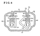
- Fig. 6 is a longitudinal cross sectional view illustrating a seat slide apparatus according to an example 4.
- Fig. 7 is an exploded perspective view illustrating a configuration of a seat slide apparatus adjusted to a vehicle according to a third embodiment of the present invention.
- Fig. 8 is a longitudinal cross sectional view illustrating the seat slide apparatus according to the third embodiment.
- Fig. 9 is an overhead cross sectional view illustrating the seat slide apparatus according to the third embodiment.
- Seat slide apparatus 1 can be preferably mounted, making a lateral pair, under a seat S of a vehicle.
- Fig. 2 illustrates only one seat slide apparatus 1 which configures the lateral pair and is mounted at the left side under the seat S, and the description will be exhibited only for the seat slide apparatus 1 at the left side of the seat S. It is, however, to be understood that both seat slide apparatus 1 possess the same general configuration and so the description below applied to both seat slide apparatus 1.
- the seat slide apparatus 1 is provided with a lower rail 11, which is fixedly mounted on a vehicle body such as a floor F and extends in a longitudinal direction, and an upper rail 12, which is secured to a bottom surface of the seat S and is mounted to be movable relative to the lower rail 11.
- the lower rail 11 serves as a first rail while the upper rail 12 serves as a second rail.
- Directions, such as “longitudinal”, “lateral” and “vertical”, which are mentioned herein, correspond to an orientation of a vehicle.
- the lower rail 11 includes a bottom wall 21 fixed to the floor F of the vehicle, first side walls 22 extending upwards from left and right ends of the bottom wall 21 and making a lateral pair, and second side walls 23 formed by bending downwards upper end portions of the first side walls 22 and making a lateral pair.
- the lower rail 11 hence exhibits a laterally symmetrical cross section extending in a longitudinal direction.
- the upper rail 12 includes an upper wall 31 secured to the seat S, first side walls 32 extending downwards from left and right ends of the upper wall 31 and making a lateral pair, and second side walls 33 formed by bending upwards lower end portions of the first side walls 32 and making a lateral pair.
- the upper rail 12 hence exhibits a laterally symmetrical cross section extending in the longitudinal direction.
- the lower rail 11 and the upper rail 12 are mechanically associated with each other in such a manner that the second side walls 23 of the lower rail 11 are interposed between the corresponding first side wall 32 and the corresponding second side wall 33, of the upper rail 12.
- Two sliding members 41 are provided between the first side wall 22 of the lower rail 11 and the second side wall 33 of the upper rail 12 at each side (left and right) of the seat slide apparatus 1, the sliding members 41 which are slidably movable in response to a longitudinal movement of the upper rail 12 relative to the lower rail 11.
- Each sliding member 41 is an assembly having a flat plate-type retainer 42 exhibiting adequate rigidity and made of metal material and at least one splierically-shaped roller 43 exhibiting adequate rigidity-
- the roller 43 is supported to be freely rotatable by a curled portion 42a formed at an upper end of the retainer 42.
- the first side wall 22 of the lower rail 11 is formed with an arc-shaped cross sectional portion 22a which supports the rollers 43 for their free rotation
- the second side wall 33 of the upper rail 12 is formed with an arc-shaped cross sectional portion 33a which also supports the rollers 43 for their free rotation.
- the rollers 43 of each sliding member 41 are press-fitted into a space between the arc-shaped cross sectional portions 22a and 33a-
- each sliding member 41 is translated in the longitudinal direction with the upper rail 12.
- At least one stopper 22b is formed or provided at the arc-shaped cross sectional portion 22a of the first side wall 22 of the lower rail 11, at the one side, and at the other side, of the seat slide apparatus 1, respectively.
- each sliding member 41 is designed to substantially meet a half of the entire length of the lower rail 11.
- each sliding member 41 can be translated half of an operation distance of the upper rail 12 relative to the lower rail 11.
- incorporated between a space defined by the lower rail 11 and the upper rail 12 are two lock members which physically lock the upper rail 11 and the lower rail 12 at plural lock positions and restrain or lock a longitudinal movement of the upper rail 12 relative to the lower rail 11.
- the space defined by the lower rail 11 and the upper rail 12 represents herein an inner space defined by the bottom wall 21 of the lower rail 11, the pair of first side walls 22 of the lower rail 11, the sliding members 41, the pair of second side walls 33 of the upper rail 12, the pair of first side walls 32 of the upper rail 12, and the upper wall 31 of the upper rail 12 (see Fig. 3).
- Each lock member 50 and 51 is operatively associated with the upper rail side 12. More specifically, each lock member 50 and 51 is operatively associated with an operation plate 52 and is secured to the upper rail 12 via a base plate 53 supporting the operation plate 52 to be movable in the longitudinal direction.
- the operation plate 52 and the base plate 53 are formed to be an approximately long plate made of metal material having adequate rigidity-
- the operation plate 52 is supported by the base plate 53 by means of pins 54 and 55.
- the base plate 53 is secured to the upper rail 12 by means of rivets 56 and 57.
- the lock members 50 and 51 are provided as a lock unit having the operation plate 52, the base plate 53, the pins 54 and 55, the rivets 56 and 57 and springs SP1 and SP2 (described later). This lock unit is then secured to the upper rail 12 by means of the rivets 56 and 57.
- Each lock member 50 and 51 is made of metal material exhibiting adequate rigidity and is formed to be substantially comb-shaped. More specifically, the lock member 50 is formed with lock teeth 50a to be engageable with engagement bores 23a of the lower rail 11 and engagement bores 32a and 33b of the upper rail 12. Likewise, the lock member 51 is formed with lock teeth 51a to be engageable with the engagement bores 23a, 32a and 33b. The engagement bores 23a, 32a and 33b are described in detail later. The lock teeth 50a and 50b are constantly biased by the corresponding elastic bodies SP1 and SP2 in a direction to be engaged with the engagement bores 23a, 32a and 33b. This direction to be engaged with the engagement bores corresponds to a lock direction.
- the lock members 50 and 51 are arranged in a symmetrical manner about a point with each other, and are biased in the lock directions towards the lateral sides of the lower rail 11, and of the upper rail 12, the lock directions which are not identical to each other.
- the lock members 50 and 51 are arranged in a vertical space between the operation plate 52 and the base plate 53 and are pivotably supported by means of the pins 54 and 55, respectively.
- the lock members 50 and 51 are operatively pivoted at horizontal surfaces with the pins 54 and 55 as pivot axes.
- the lock teeth 50a of the lock member 50 are mounted at a vertically higher surface than the lock teeth 51a of the lock member 51, i.e., are mounted closer to the bottom surface of the seat S than the lock teeth 51a of the lock member 51 are. Consequently, the lock teeth 50a are pivoted at a horizontal surface which is different from the one of the lock teeth 51a.
- the operation plate 52 is provided with oblong bores 52a and 52b at longitudinal both ends thereof.
- the pins 54 and 55 being fitted into the oblong bores 52a and 52b are fixed to the base plate 53 in a condition where the lock members 50 and 51 are pivotally supported by the pins 54 and 55. Therefore, by virtue of the pins 54 and 55 fitted into the oblong bores 52a and 52b, which serve as guides, the operation plate 52 is restrained or locked from vertical and lateral movements and is allowed to move only in the longitudinal direction.
- the operation plate 52 is formed or provided with sloped bores 52c and 52d which are positioned at an approximately central portion of the operation plate 52 and adjacent to the oblong bores 52a and 52b.
- the sloped bores 52c and 52d respectively exhibit a flat and approximately triangle shape and possess different lateral widths at front and rear ends thereof. More specifically, each sloped bore 52c and 52d possess a superior or large lateral width at a front end thereof and an inferior or small lateral width at a rear end thereof.
- the sloped bores 52c and 52d are fitted with guide pins 58 and 59 securely attached to the lock members 50 and 51.
- the guide pin 58 can shift along an inner wall surface between the front end having the large lateral width and the rear end having the small lateral width, of the sloped bore 52c, while the guide pin 59 can shift along an inner wall surface between the front end having the large lateral width and the rear end having the small lateral width, of the sloped bore 52d.
- each lock member 50 and 51 When each guide pin 58 and 59 shifts to the front end having the large lateral width of each sloped bore 52c and 52d, each lock member 50 and 51 is pivoted to a lock position, which corresponds to the engagement position of each lock teeth 50a and 51 a with the engagement bores 23a, 32a and 33b. When each guide pin 58 and 59 shifts to the rear end having the small lateral width of each sloped bore 52c and 52d, each lock member 50 and 51 is pivoted to a unlock position (a disengagement position).
- each lock member 50 and 51 is operated to lock and unlock a relative movement between lower rail 11 and the upper rail 12 with each pin 58 and 59 as a pivot axis.
- each guide pin 58 and 59 is attached to each lock member 50 and 51 as an independent component.
- each guide pin 58 and 59 can be integrally formed with each lock member 50 and 51, such as a projection.
- the operation plate 52 is connected with an initial position return elastic body k for biasing constantly the operation plate 52 in such a manner that the guide pins 58 and 59 are shifted towards the front ends having a large lateral width, i.e., in the lock direction.
- an operation handle not illustrated
- each lock member 50 and 51 can be returned to, or maintained at, a lock position by virtue of a biasing force of the initial position return elastic body k and a biasing force of each elastic body SP1. and SP2 biasing each lock member 50 and 51 to the lock direction.
- each elastic body SP1 and SP2 is configured with a torsion spring. More specifically, each torsion spring SP1 and SP2 is fitted into each pin 54 and 55 and one end of each is hooked at each guide pin 58 and 59. Therefore, each torsion spring SP1 and SP2 effectively bias each lock member 50 and 51 in the lock direction, i.e., in a counterclockwise direction in Fig. 4.
- the pair of second side walls 23 of the lower rail 11 is provided with the engagement bores 23a extending continuously and longitudinally with a pitch equally spaced between each adjacent bore 23a over a longitudinal movement range of the upper rail 12 and in a symmetrical manner in a vehicle lateral direction. More specifically, the engagement bores 23a are formed at the one (e.g., an upper side in Fig.
- the engagement bores 23a of the one of the second side walls 23 are arranged in a substantially laterally symmetric manner relative to the engagement bores 23a of the other one of the second side walls 23. Meanwhile, the position, at which each the lock member 50 and the lock member 51 is engaged with the first and second side walls 32 and 33 of the upper rail 12, is shifted, between the lock members 50 and 51, half of the equally spaced longitudinal pitch for the engagement bores 23a of the lower rail 11.
- the engagement bores 32a are formed at the one (e.g., an upper side in Fig. 4) of the first side walls 32 are shifted, relative to the engagement bores 32a formed at the other one (e.g., a lower side in Fig. 4) of the first side walls 32, half of the equally spaced longitudinal pitch for the engagement bores 23a.
- the engagement bores 33b are formed at the one (e.g., the upper side in Fig. 4) of the second side walls 33 are shifted, relative to the engagement bores 33b formed at the other one (e.g., the lower side in Fig. 4) of the second side walls 33.
- the lock teeth 50a are shifted from the lock teeth 5 1 a half of the equally space longitudinal pitch for the engagement bores 23a.
- the engagement bores 32a and 33b are positioned at the upper rail 12 in such a manner that the lock teeth 50a and 51a of each lock member 50 and 51 are respectively engaged therewith, such as approximately longitudinally intermediate positions of the upper rail 12.
- the engagement bores 23a, 32a and 33b are formed corresponding to the engagement operation position of each lock member 50 and 51, it is possible to selectively engage the lock teeth 50a or 51a with the engagement bores 23a, 32a and 33b. Consequently, it is possible to implement an adjustment of a longitudinal position of the upper rail 12 relative to the lower rail 11 every half of the pitch p of the engagement bores 23a.
- the lock teeth 50a (alternatively or in addition the lock teeth 51a) are engaged with the engagement bores 23a, 32a and 33b crossing over the second side wall 23 of the lower rail 11, and the first and second side walls 32 and 33 of the upper rail 12. That is, as illustrated in Figs. 3 and 4, because each lock teeth 50a and 51a are engaged with the engagement bores 33b of the second side wall 33 of the upper rail 12 as well as with the engagement bores 32a of the first side wall 32 of the upper rail 12 and the engagement bores 23a of the second side wall 23 of the lower rail 11, a lock mechanism of each lock member 50 and 51 becomes a bar-tacking structure.
- each lock teeth 50a and 51 a are engaged with a single side wall of the lower rail 11 and a single side wall of the upper rail 12, it is possible to enhance a degree of shearing strength of each lock member 50 and 51 as well as downsizing the seat slide apparatus 1, and to further enhance a degree of locking strength of each lock member 50 and 51.
- each sliding position of each sliding member 41 between the lower rail 11 and the upper rail 12 does not interfere in an engagement position of each lock member 50 and 51 with the engagement bores 23a, 32a and 33b, and vice versa. More specifically, each sliding member 41 is positioned downsides of a vertically intermediate position between the lower rail 11 and the upper rail 12, while each lock member 50 and 51 is positioned upsides of the vertically intermediate position therebetween.
- each sliding member 41 is positioned at a vertical height different from the one of each lock member 50 and 51, and each sliding member 41 can operate at a position not interfering in each lock member 50 and 51, vice versa, a longitudinal length of each sliding member 41 is not unnecessarily responsive to a longitudinal length of the lock mechanism and can be controlled at the minimum length possible.
- the lengths of the lower rail 11 and the upper rail 12 can be controlled at the minimum length possible that substantially satisfies a moving amount ofthe upper rail 12, the same which effectively leads to further downsizing of the seat slide apparatus I adjusted to a vehicle.
- the lock teeth 50a or 51 a are selectively engaged with the engagement bores 23a, 32a and 33b of the lower rail 11 and the upper rail 12. Consequently, a longitudinal movement of the upper rail 12 relative to the lower rail 11 can be effectively restrained or locked, and the seat S is hence held at a predetermined position relative to the floor F.
- each guide pin 58 and 59 is shifted to the rear end having the small lateral width of each sloped bore 52c and 52d against a biasing force of each elastic body SP1 and SP2, and as a consequence, each lock member 50 and 51 is operated to unlock the relative movement of the lower rail 11 and the upper rail 12.
- the lock teeth 50a (or the lock teeth 51 a) are released from being engaged with the engagement bores 23a, 32a and 33b. Therefore, the upper rail 12 is allowed to move relative to the lower rail 11, and the seat S is allowed to slide longitudinally relative to the floor F.
- the plural lock members 50 and 51 (two according to the first embodiment) which lock the lower rail 11 and the upper rail 12 at plural engagement positions or stages and restrain a relative movement of the upper rail 12 relative to the lower rail 11, are housed in the space surrounded by the lower rail 11 and the upper rail 12. Therefore, it is possible to reduce an entire size of the seat slide apparatus 1 adjusted to a vehicle.
- Each sliding member 41 is positioned at a vertical position (height) being different from a vertical position (height) of each lock member 50 and 51, and each lock member 50 and 51 does not interfere in each sliding member 41, vice versa. Therefore, a longitudinal length of each sliding member 41 is not influenced by a longitudinal length of the lock mechanism, vice versa, and can be controlled at the minimum length possible. In other words, without being influenced by the length, of each sliding member 41 and the lock mechanism, the lengths of the lower rail 11 and the upper rail 12 can be controlled at the minimum length possible that substantially satisfies a moving amount of the upper rail 12, the same which effectively leads to downsizing of the seat slide apparatus 1 adjusted to a vehicle.
- the lock teeth 50a (alternatively or in addition the lock teeth 51a) are brought into engagement with the second side wall 23 of the lower rail 11, the first side wall 32 and the second side wall 33 of the upper rail 12. Likewise, the lock teeth 51a are brought into engagement with the second side wall 23 of the lower rail 11, the first side wall 32 and the second side wall 33 of the upper rail 12.
- the lock mechanism is a bar-tacking structure, and it is possible to enhance a degree of locking strength of the lock mechanism.
- the lock mechanism by which a position of the seat S can be finely adjusted, is substantially configured with the lock members 50 and 51, the operation plate 52, the pins 54 and 55, and the elastic body SP1 and SP2- Therefore, it is possible to reduce the number of components to the minimum quantity possible and reduce the manufacturing cost. More over, the reduction of the number of components effectively leads to facilitating an assembling procedure.
- a configuration of a seat slide apparatus 1 of the second embodiment is substantially identical to the above-described configuration of the seat slide apparatus I of the first embodiment, and yet there is a difference therebetween in so far as the engagement operation positions of the lock members 50 and 51 and the positions of the engagement bores 23a, 32a and 33b.
- the components used herein in the same manner as the first embodiment are denoted with the same reference numerals.
- the engagement bores 23a are formed or provided continuously and longitudinally at the pair of second side walls 23 of the lower rail 11 with a pitch equally spaced between each adjacent bore 23a and shifted, in a longitudinal direction between the pair of second side walls 23, every half of the pitch for the engagement bores 23a. More specifically, the engagement bores 23a at the one (the upper side in Fig. 5) of the second side walls 23 of the lower rail 11 are shifted, every half of the pitch for the engagement bores 23a, relative to the engagement bores 23a at the other one (the lower side in Fig. 5) of the second side walls 23.
- the position, at which each the lock member 50 and 51 is engaged with the first and second side walls 32 and 33 of the upper rail 12, is provided in a symmetrical manner in a vehicle lateral direction. More specifically, the engagement bores 32a of one of the first side walls 32 of the upper rail 12 (e.g., the upper side in Fig. 5) longitudinally extends in a substantially laterally symmetric manner relative to the engagement bores 32a of the other one of the first side walls 32 of the upper rail 12 (e.g., the lower side in Fig- 5). Likewise, the engagement bores 33b of the one of the second side walls 33 of the upper rail 12 (e.g., the upper side in Fig.
- the lock teeth 50a are arranged substantially in a symmetrical manner relative to the lock teeth 51a.
- the seat slide apparatus has two lock members 50 and 51.
- the number of the lock members can be one, three or more than three.
- the engagement bores 32a of the one of the first side walls 32 e.g., the upper side in Fig. 4
- the lock member can be shifted, between each lock member, every amount arbitrarily obtained by "pitch P/ the number of lock members N", relative to the engagement bores 32a of the other one of the first side walls 32 (e.g., the lower side in Fig. 4).
- the engagement bores 33b of the one of the second side walls 33 (e.g., the upper side in Fig. 4), with which the lock member is engaged, can be shifted, between each lock member, every amount arbitrarily obtained by "pitch P/the number of lock members N", relative to the engagement bores 33b of the other one of the second side walls 33 (e.g., the lower side in Fig. 4).
- the engagement bores 23a of the one of the second side walls 23 e.g., the upper side in Fig. 5
- the engagement bores 23a of the other one of the second side walls 23 (e.g., the lower side in Fig. 5).
- the lock members 50 and 51 are arranged in a symmetrical manner about a point with each other and are engaged with the engagement bores 23a, 32a and 33b at both left and right sides of the lower rail 11 and the upper rail 12.
- the lock members 50 and 51 can be engaged with the engagement bores 23a, 32a and 33b defined only at one side (left side or right side) of each the lower rail 11 and the upper rail 12.
- the engagement bores 23a of the one of the second side walls 23 extend in the longitudinal direction having a longitudinal gap corresponding to a length obtained by "p/N" relative to the engagement bores 23a of the other one of the second side walls 23 (e.g., the lower side in Fig. 5).
- two rows of engagement bores 23a can be formed or provided at one of the second side walls 23 of the lower rail 11. and cab extend longitudinally at different heights. In this case, the upper row having the engagement bores 23a can be shifted, relative to the lower row having the engagement bores 23a, in a longitudinal direction every half of the pitch for the engagement bores 23a.
- a seat slide apparatus 71 for a vehicle is provided with a lower rail 72 and an upper rail 73 mounted on the lower rail 72 to be relatively movable in a longitudinal direction.
- the lower rail 72 includes a bottom wall 81, first side walls 82 extending upwards from left and right ends of the bottom wall 82 and making a lateral pair, and second side walls 83 formed by bending downwards upper end portions of the first side walls 82 and making a lateral pair.
- the upper rail 73 includes an upper wall 91, first side walls 92 extending downwards from left and right ends of the upper wall 91 and making a lateral pair, and second side walls 93 formed by bending upwards lower end portions of the first side walls 92 and making a lateral pair.
- two lock members 101 and 102 are housed in a space defined or surrounded by the lower rail 72 and the upper rail 73, and are pivotably supported by a shaft (not illustrated) longitudinally extending at a clinch portion between the first side wall 92 and the second side wall 93 at the respective sides.
- Each lock member 101 and 102 is pivoted at a plan surface perpendicular to a horizontal surface. It is hence possible to selectively engage either the lock member 101 or the lock member 102 with engagement bores 83a, 92a and 93a of the lower rail 72 and the upper rail 73, by which the same effects as the above described embodiments can be exerted.
- the first rail is represented by the lower rail 11 fixed to the floor F and the second rail is represented by the upper rail 12 secured to the seat S.
- the first rail can be represented by the upper rail 12 fixedly mounted on the floor F and the second rail can be represented by the lower rail 11 secured to the seat S.
- the lock mechanism (the lock unit) can be fixedly attached to the lower rail 11 secured to the seat S.
- the elastic bodies SP1 and SP2 which biases the lock members 50 and 51 in the lock direction, are represented by torsion springs.
- the elastic bodies SP1 and SP2 can be represented by leaf springs and so on.
- each sliding member 41 is not limited to the above descriptions.
- the number of rollers 43 attached to the retainer 42 can be one, two, three, or more.
- the two sliding members 41 at both left and right sides between the lower rail 11 and the upper rail 12. That is, totally provided are the four sliding members 41 in the seat slide apparatus described above.
- the number of the sliding members 41 is not limited to the above and can be more than two.
- the base plate 53 is not essential to achieve the present invention.
- the base plate 53 described above is employed for assembling the lock members 50 and 5 1 as a lock unit and serves to facilitate attaching the lock members 50 and 51 to the upper rail 12 and to stably secure the lock members 50 and 51 to the upper rail 12. Therefore, the lock members 50 and 51 can be secured to the upper rail 12 by fixing the pins 54 and 55, for example directly to the upper rail 12.
- engagement bores can be further provided at the first side walls 22 of the lower rail 11.
- the lock teeth 50a of the lock member 50 are engaged with the engagement bores of the two side walls of the lower rail 11 and the two side walls of the upper rail 12.
- the lock teeth 51a of the lock member 51 are engaged with the engagement bores of the two side walls of the lower rail 11 and the two side walls of the upper rail 12.
- the lock teeth 50a of the lock member 50 can be engaged in this order with the first side wall 32 of the upper rail 12, the second side wall 23 of the lower rail 11, the second side wall 33 of the upper rail 12 and the first side wall of the lower rail 11.
- the lock teeth 51a of the lock member 51 can be engaged in the same manner.
- the seat slide apparatus of the illustrated embodiments is characterized in that the lock members are pivotably supported by the pins secured in a vehicle vertical direction in the space defined by the first rail and the second rail and are operated to lock using a horizontal locking movement with the pins as pivot axes. According to this configuration, it is possible to operate the lock members effectively applying a space longitudinally extending in the space surrounded by the first and second rails, the same which leads to reducing a space required for the lock mechanism. As described above, the lock mechanism according to the embodiments and examples of the present invention, in terms of a structure that the lock members are housed in the space defined by the first and second rails, can effectively achieve downsizing of the seat slide apparatus adjusted to a vehicle.
- the seat slide apparatus of the illustrated embodiments each has an operation plate, which is operatively associated with the lock members and operates for locking and unlocking the lock members, housed in the space surrounded by the first and second rails.
- Each operation plate is provided with the oblong bores, by which the operation plate is allowed to operate in a longitudinal direction for relatively moving the second rail with the pins extending through the oblong bores and is not allowed to operate in vertical and lateral directions, and the operation plate is further provided with second guide bores, which the guide pins attached to, or projections formed at, the respective lock members are inserted into and guide the lock members to rotate between the lock position and the unlock position on the basis of the longitudinal operation of the operation plate.
- the operation plate housed in the space defined by the first and second rails is the operation plate, which operates the lock members to lock and unlock, as well as the lock members. Therefore, it is possible to downsize the entire structure of the seat slide apparatus. Moreover, according to this configuration, because the operation plate is operated in a direction being parallel with a moving direction (a longitudinal direction) of the second rail, it is possible to downsize the lock mechanism without being influenced by the lateral lengths of the first and second rails.
- the oblong bores 52a and 52b, through which the pins 54 and 55 extend, are structured as first guide bores, while the sloped bores 52c and 52d, through which the guide pins 58 and 59 extend, are structured as the second guide bores, as illustrated in Fig. 1.
- the seat slide apparatus of the illustrated embodiments each comprises sliding members which include: rollers slidably rotatable between the first rail and the second rail; and a retainer freely rotatably supporting the rollers.
- sliding members which include: rollers slidably rotatable between the first rail and the second rail; and a retainer freely rotatably supporting the rollers.
- two sliding members at both left and right sides between the first rail and the second rail. According to this configuration, it is possible to stabilize a degree of sliding friction applied to the first and second rails relatively moving and to position the lock members and the sliding members so as not to mutually interfere.
- a seat slide apparatus 1 according to a third embodiment of the present invention which is mounted, making a lateral pair, under the seat S of a vehicle, as is illustrated in Fig. 2.
- the seat slide apparatus 1 is provided with the lower rail 11, which is fixedly mounted on a vehicle body such as the floor F and extends in a longitudinal direction, and the upper rail 12, which is secured to a bottom surface of the seat S and is mounted to be movable relative to the lower rail 11.
- the lower rail 11 serves as the first rail while the upper rail 12 serves as the second rail.
- Directions, such as “longitudinal”, “lateral” and “vertical”, which are mentioned herein, correspond to an orientation of a vehicle.
- the lower rail 11 includes the bottom wall 21 fixed to the floor F of the vehicle, the first side walls 22 extending upwards from the left and right ends of the bottom wall 21 and making a lateral pair, and the second side walls 23 formed by bending downwards the upper end portions of the first side walls 22 and making a lateral pair.
- the lower rail 11 hence exhibits a laterally symmetrical cross section extending in a longitudinal direction.
- the upper rail 12 includes the upper wall 31 secured to the seat S, the first side walls 32 extending downwards from the left and right ends of the upper wall 31 and making a lateral pair, and the second side walls 33 formed by bending upwards the lower end portions of the first side walls 32 and making a lateral pair.
- the upper rail 12 hence exhibits a laterally symmetrical cross section extending in the longitudinal direction.
- the lower rail 11 and the upper rail 12 are mechanically associated with each other in such a manner that the second side walls 23 of the lower rail 11 are interposed between the corresponding first side wall 32 and the corresponding second side wall 33, of the upper rail 12.
- the two sliding members 41 are provided between the first side wall 22 of the lower rail 11 and the second side wall 33 of the upper rail 12 at each side (left and right) of the seat slide apparatus 1, the sliding members 41 which are slidably movable in response to a longitudinal movement of the upper rail 12 relative to the lower rail 11.
- Each sliding member 41 is an assembly having the flat plate-type retainer 42 exhibiting adequate rigidity and made of metal material and the at least one spherically-shaped roller 43 exhibiting adequate rigidity-
- the roller 43 is supported to be freely rotatable by the curled portion 42a formed at the upper end of the retainer 42.
- the first side wall 22 of the lower rail 11 is formed or provided with the arc-shaped cross sectional portion 22a which supports the rollers 43 for their free rotation
- the second side wall 33 of the upper rail 12 is formed or provided with the arc-shaped cross sectional portion 33a which also supports the rollers 43 for their free rotation.
- the rollers 43 of each sliding member 41 are press-fitted into a space between the arc-shaped cross sectional portions 22a and 33a.
- each sliding member 41 is translated in the longitudinal direction with the upper rail 12.
- the at least one stopper 22b is formed or provided at the arc-shaped cross sectional portion 22a of the first side wall 22 of the lower rail 11, at the one side, and at the other side, of the seat slide apparatus 1 respectively.
- the three stoppers 22b provided are the three stoppers 22b; the first one of which is positioned at a longitudinal front end of the lower rail 11; the second one of which is positioned at a longitudinal rear end of the lower rail 11; and the third one of which is positioned at a substantially longitudinal intermediate portion of the lower rail 11.
- each sliding member 41 is designed to substantially meet a half of the entire length of the lower rail 11.
- each sliding member 41 can be translated half of an operation distance of the upper rail 12 relative to the lower rail 11.
- a lock member 51 which physically locks the upper rail 11 and the lower rail 12 at plural lock positions (longitudinal direction) and restrains or locks a longitudinal movement of the upper rail 12 relative to the lower rail 11.
- the space defined by the lower rail 11 and the upper rail 12 represents herein an inner space defined or surrounded by the bottom wall 21 of the lower rail 11, the pair of first side walls 22 of the lower rail 11, the sliding members 41, the pair of second side walls 33 of the upper rail 72, the pair of first side walls 32 of the upper rail 12, and the upper wall 31 of the upper rail 12 (see Fig. 8).
- the lock member 51 is operatively associated with the upper rail side 12. More specifically, the lock member 51 is operatively associated with an operation plate 52 and is secured to the upper rail 12 via a base plate 53 supporting the operation plate 52 to be movable in the longitudinal direction.
- the operation plate 52 and the base plate 53 are formed to be an approximately long plate made of metal material having adequate rigidity.
- the operation plate 52 is supported by the base plate 53 by means of pins 54 and 55.
- the base plate 53 is secured to the upper rail 12 by means of the rivets 56 and 57-
- the lock member 51 is provided as a lock unit having the operation plate 52, the base plate 53, the pins 54 and 55, the rivets 56 and 57 and an elastic body SP (described later). This lock unit is then secured to the upper rail 12 by means of the rivets 56 and 57.
- the lock member 51 is made of metal material exhibiting adequate rigidity and is formed to be substantially comb-shaped. More specifically, the lock member 51 is formed with lock teeth 51a engageable with the engagement bores 23a, 32a and 33b.
- the engagement bores 23a, 32a and 33b are described in detail later.
- the lock teeth 51a are constantly biased by the elastic body SP in a direction to be engaged with the engagement bores 23a, 32a and 33b.
- the lock member 51 is arranged in a vertical space between the operation plate 52 and the base plate 53 and is pivotably supported by means of the pin 54.
- the lock member 51 is operatively pivoted at a horizontal surface with the pin 54 as a pivot axis.
- the operation plate 52 is provided with the oblong bores 52a and 52b at longitudinal both ends thereof.
- the pins 54 and 55 being fitted into the oblong bores 52a and 52b are fixed to the base plate 53 in a condition where the lock member 51 is pivotally supported by the pin 54. Therefore, by virtue of the pins 54 and 55 fitted into the oblong bores 52a and 52b, which serve as guides, the operation plate 52 is restrained or locked from vertical and lateral movements and is allowed to move only in the longitudinal direction.
- the operation plate 52 is formed or provided with a sloped bore 52c which is positioned at an approximately central portion of the operation plate 52 and adjacent to the oblong bore 52a.
- the sloped bore 52c exhibits a flat and approximately triangle shape and possesses different lateral widths at front and rear ends thereof. More specifically, the sloped bore 52c possesses a superior or large lateral width at a front end thereof and an inferior or small lateral width at a rear end thereof. As illustrated in Fig. 7, the sloped bore 52c is fitted with a guide pin 58 securely attached to the lock member 51.
- the guide pin 58 can shift along an inner wall surface between the front end having the large lateral width and the rear end having the small lateral width, of the sloped bore 52c.
- the lock member 51 is pivoted to a lock position, which corresponds to the engagement position of the lock teeth 51a with the engagement bores 23a, 32a and 33b.
- the lock member 51 is pivoted to an unlock position (a disengagement position).
- the lock member 51 is operated to lock and unlock a relative movement between lower rail 11 and the upper rail 12 with the pin 54 as a pivot axis.
- the guide pin 58 is attached to the lock member 51 as an independent component.
- the guide pin 58 can be integrally formed with the lock member 51, such as a projection.
- the operation plate 52 is connected with an initial position return elastic body k for biasing constantly the operation plate 52 in such a manner that the guide pin 58 is shifted towards the front end having a large lateral width, i.e., in the lock direction.
- an operation handle not illustrated
- the lock member 51 it is possible to operate the lock member 51 to unlock a relative movement of the upper rail 12 and the lower rail 11.
- the lock member 51 can be returned to, or maintained at, a lock position by virtue of a biasing force of the initial position return elastic body k and a biasing force of each elastic body SP biasing the lock member 51 to the lock direction.
- the elastic body SP is configured with a torsion spring. More specifically, the torsion spring SP is fitted into the pin 54 and one end of the torsion spring SP is hooked at the guide pin 58. Therefore, the torsion spring SP effectively biases the lock member 51 in the lock direction, i.e., in a counterclockwise direction in Fig. 9.
- the engagement bores 23a of the lower rail 11 extend continuously and longitudinally with a pitch equally spaced between each adjacent bore 23a corresponding to a longitudinal movement range of the upper rail 12. More specifically, the engagement bores 23a extend continuously and longitudinally at only one (e.g., an upper side in Fig. 9) of the second side walls 23 with a pitch equally spaced between each adjacent bore 23a corresponding to a longitudinal movement range of the upper rail 12. Meanwhile, the engagement bores 32a and 33b are formed at the first and second side walls 32 an 33 of the upper rail 12, the first and second side walls 32 and 33 which are laterally at the same side as the one of the second side walls 23 having the engagement bores 23a. The engagement bores 32a and 33b are hence positioned at the upper rail 12 in such a manner that the lock teeth 51a of the lock member 51 are engaged therewith, such as approximately longitudinal intermediate position ofthe upper rail 12.
- the lock teeth 51a of the lock member 51 which is housed in the space defied or surrounded by the lower rail 11 and the upper rail 12, are operatively engaged with the engagement bores of the lower rail 11 and the engagement bores 32a and 33b of the upper rail 12.
- the lock teeth 51a are engaged with the engagement bores 23a, 32a and 33b crossing over the second side wall 23 of the lower rail 11, and the first and second side walls 32 and 33 of the upper rail 12, between which the second side wall 23 of the lower rail 11 interpose.
- a lock mechanism becomes a bar-tacking structure.
- a lock mechanism compared with a structure in which the lock teeth 51a are engaged with a single side wall of the lower rail 11 and a single side wall of the upper rail 12, it is possible to enhance a degree of shearing strength of the lock member 51, and to further enhance a degree of locking strength of the lock member 51.
- each sliding member 41 when the lock member 51 is operated in the lock direction, a sliding position of each sliding member 41 between the lower rail 11 and the upper rail 12 does not interfere in an engagement position of the lock member 51 with the engagement bores 23a, 32a and 33b, and vice versa. More specifically, each sliding member 41 is positioned downsides of a vertically intermediate position between the lower rail 11 and the upper rail 12, while the lock member 51 is positioned upsides of the vertically intermediate position therebetween.
- each sliding member 41 is positioned at a vertical height different from the o lock member 51, and each sliding member 41 can operate at a position not interfering in the lock member 51, vice versa, a longitudinal length of each sliding member 41 is not unnecessarily responsive to a longitudinal length of the lock mechanism and can be controlled at the minimum length possible.
- the lengths of the lower rail 11 and the upper rail 12 can be controlled at the minimum length possible that substantially satisfies a moving amount of the upper rail 12, the same which effectively leads to further downsizing of the seat slide apparatus 1 adjusted to a vehicle.
- the lock teeth 51a are engaged with the engagement bores 23a, 32a and 33b of the lower rail 11 and the upper rail 12- Consequently, a longitudinal movement of the upper rail 12 relative to the lower rail 11 can be effectively restrained or locked, and the seat S is hence held at a predetermined position relative to the floor F.
- the lock teeth 51a are released from being engaged with the engagement bores 23a, 32a and 33b. Therefore, the upper rail 12 is allowed to move relative to the lower rail 11, and the seat S is allowed to slide longitudinally relative to the floor F. As described above, it is possible to adjust a longitudinal position of the seat S relative to the floor F.
- the lock member 51 which locks the lower rail 11 and the upper rail 12 at plural engagement positions or stages and restrains a relative movement of the upper rail 12 relative to the lower rail 11, is housed in the space surrounded by the lower rail 11 and the upper rail 12. Therefore, it is possible to reduce an entire size of the seat slide apparatus 1 adjusted to a vehicle.
- Each sliding member 41 is positioned at a vertical position (height) being different from a vertical position (height) of the lock member 51, and the lock member 51 does not interfere in each sliding member 41, vice versa. Therefore, a longitudinal length of each sliding member 41 is not influenced by a longitudinal length of the lock mechanism, vice versa, and can be controlled at the minimum length possible. In other words, without being influenced by the length, of each sliding member 41 and the lock mechanism, the lengths of the lower rail 11 and the upper rail 12 can be controlled at the minimum length possible that substantially satisfies a moving amount of the upper rail 12, the same which effectively leads to downsizing of the seat slide apparatus 1 adjusted to a vehicle.
- the lock teeth 51a are brought into engagement with the second side wall 23 of the lower rail II, the first side wall 32 and the second side wall 33 of the upper rail 12, between which the second side wall 23 interposes.
- the lock mechanism is a bar-tacking structure, and it is possible to enhance a degree of locking strength of the lock mechanism.
- the first rail is represented by the lower rail 11 fixed to the floor F and the second rail is represented by the upper rail 12 secured to the seat S.
- the first rail can be represented by the upper rail 12 fixedly mounted on the floor F and the second rail can be represented by the lower rail 11 secured to the seat S.
- the lock mechanism (the lock unit) can be fixedly attached to the lower rail 11 secured to the seat S.
- the elastic body SP which biases the lock member 51 in the lock direction, is represented by a torsion spring.
- the elastic body SP can be represented by a leaf spring and so on.
- the lock member 51 is operated at a horizontal surface.
- the lock member 51 does not interfere in sliding movement of each sliding member 41, in order to lock, the lock member 51 can be operated in a flat surface perpendicular to a horizontal surface for example.
- each sliding member 41 is not limited to the above descriptions.
- the number of rollers 43 attached to the retainer 42 can be one, two, three, or more.
- the two sliding members 41 at both left and right sides are provided between the lower rail 11 and the upper rail 12. That is, four sliding members 41 in total are provided in the seat slide apparatus described above.
- the number of the sliding members 41 is not limited to the above and can be more than two.
- the base plate 53 is not essential to achieve the present invention.
- the base plate 53 described above is employed for assembling the lock member 51 as a lock unit and serves to facilitate attaching the lock member 51 to the upper rail 12 and to stably secure the lock member 51 to the upper rail 12- Therefore, the lock member 51 can be secured to the upper rail 12 by fixing the pin 54, for example directly to the upper rail 12.
- engagement bores can be further provided at the first side walls 22 of the lower rail 11.
- the lock teeth 51a of the lock member 51 are engaged with the engagement bores of the two side walls of the lower rail 11 and the two side walls of the upper rail 12.
- the lock teeth 51a of the lock member 51 can be engaged in this order with the first side wall 32 of the upper rail 12, the second side wall 23 of the lower rail 11, the second side wall 33 of the upper rail 12 and the first side wall of the lower rail 11.
- the seat slide apparatus of the above embodiment is characterized in that the operation plate, which is operatively associated with the lock member and operates for locking and unlocking the lock member, is housed in the space surrounded by the first and second rails, the operation plate is provided with the oblong bore, by which the operation plate is allowed to operate in a longitudinal direction for relatively moving the second rail with the pin extending through the oblong bores and is not allowed to operate in vertical and lateral directions, and the operation plate is further provided with a second guide bore, which the guide pin is attached to, or a projection formed at, the lock member is inserted into and guides the lock member to rotate between the lock position and the unlock position on the basis of the longitudinal operation of the operation plate.
- the operation plate housed in the space defined by the first and second rails is the operation plate, which operates the lock member to lock and unlock, as well as the lock member. Therefore, it is possible to downsize the entire structure of the seat slide apparatus. Moreover, according to this configuration, because the operation plate is operated in a direction being parallel with a moving direction (a longitudinal direction) of the second rail, it is possible to downsize the lock mechanism without being influenced by the lateral lengths of the first and second rails.
- the oblong bore 52a, through which the pin 54 extends, are structured as a first guide bore, while the sloped bores 52c, through which the guide pin 58 extend, is structured as the second guide bore, as illustrated in Fig. 7.
- each sliding member includes: rollers slidably rotatable between the first rail and the second rail; and a retainer freely rotatably supporting the rollers.
- two sliding members at both left and right sides between the first rail and the second rail. According to this configuration, it is possible to stabilize a degree of sliding friction applied to the first and second rails relatively moving and to position the lock member and the sliding members so as not to mutually interfere.
Landscapes
- Engineering & Computer Science (AREA)
- Aviation & Aerospace Engineering (AREA)
- Transportation (AREA)
- Mechanical Engineering (AREA)
- Seats For Vehicles (AREA)
Applications Claiming Priority (2)
| Application Number | Priority Date | Filing Date | Title |
|---|---|---|---|
| JP2004367970A JP2006168688A (ja) | 2004-12-20 | 2004-12-20 | 車両用シートスライド装置 |
| JP2004370430A JP2006175966A (ja) | 2004-12-22 | 2004-12-22 | 車両用シートスライド装置 |
Publications (3)
| Publication Number | Publication Date |
|---|---|
| EP1671836A2 true EP1671836A2 (fr) | 2006-06-21 |
| EP1671836A3 EP1671836A3 (fr) | 2006-07-05 |
| EP1671836B1 EP1671836B1 (fr) | 2007-10-03 |
Family
ID=36027224
Family Applications (1)
| Application Number | Title | Priority Date | Filing Date |
|---|---|---|---|
| EP05077947A Expired - Fee Related EP1671836B1 (fr) | 2004-12-20 | 2005-12-20 | Glissière de siège pour un véhicule |
Country Status (3)
| Country | Link |
|---|---|
| US (1) | US7328877B2 (fr) |
| EP (1) | EP1671836B1 (fr) |
| DE (1) | DE602005002720T2 (fr) |
Cited By (5)
| Publication number | Priority date | Publication date | Assignee | Title |
|---|---|---|---|---|
| WO2013059312A1 (fr) | 2011-10-17 | 2013-04-25 | Fisher & Company, Incorporated | Ensemble de glissières de siège |
| WO2013119411A1 (fr) * | 2012-02-06 | 2013-08-15 | Johnson Controls Technology Company | Ensemble de réglage de position pour siège de véhicule |
| US9108533B2 (en) | 2010-05-28 | 2015-08-18 | Brose Fahrzeugteile Gmbh & Co. Kg, Coburg | Longitudinal guide for a motor vehicle seat |
| US10266074B2 (en) | 2011-10-17 | 2019-04-23 | Fisher & Company, Incorporated | Seat-track assembly |
| US11225173B2 (en) | 2020-02-12 | 2022-01-18 | Fisher & Company, Incorporated | Seat-track assembly |
Families Citing this family (63)
| Publication number | Priority date | Publication date | Assignee | Title |
|---|---|---|---|---|
| JP4631327B2 (ja) * | 2004-06-28 | 2011-02-16 | アイシン精機株式会社 | 車両用シート装置 |
| JP4534828B2 (ja) * | 2005-03-24 | 2010-09-01 | アイシン精機株式会社 | 車両用シート装置 |
| JP4774913B2 (ja) * | 2005-10-25 | 2011-09-21 | アイシン精機株式会社 | 車両用シートスライド装置およびその組み立て方法 |
| US7665791B2 (en) * | 2006-04-14 | 2010-02-23 | Aisin Seiki Kabushiki Kaisha | Seat slide device for vehicle |
| US7648115B2 (en) * | 2006-06-20 | 2010-01-19 | Deere & Company | Seat slide locator |
| GB0616733D0 (en) * | 2006-08-23 | 2006-10-04 | Accuride Int Ltd | A sliding support assembly |
| JP2008049891A (ja) * | 2006-08-25 | 2008-03-06 | Aisin Seiki Co Ltd | 車両用シートスライド装置 |
| JP2008074380A (ja) * | 2006-08-25 | 2008-04-03 | Aisin Seiki Co Ltd | 車両用シートスライド装置 |
| CN101795599A (zh) * | 2007-06-11 | 2010-08-04 | 江森自控科技公司 | 闩锁机构 |
| JP2009101955A (ja) * | 2007-10-25 | 2009-05-14 | Aisin Seiki Co Ltd | 車両用シートスライド装置 |
| US8215602B2 (en) * | 2008-05-23 | 2012-07-10 | Lear Corporation | Longitudinal adjustment apparatus for a vehicle seat |
| WO2010080601A1 (fr) * | 2008-12-18 | 2010-07-15 | Lear Corporation | Système de blocage à enclenchement positif pour siège de véhicule |
| DE112009003579B4 (de) * | 2008-12-19 | 2023-01-26 | Lear Corporation | Sitz-Verstellvorrichtung und Fahrzeugsitzanordnung |
| US8376460B2 (en) * | 2009-02-26 | 2013-02-19 | Hema Engineering Industries Limited | Seat track assembly |
| DE102009033892B4 (de) * | 2009-07-20 | 2017-03-30 | Lear Corporation | Sitzschienenanordnung mit Sitzverriegelung und Memoryelement für Fahrzeugsitz |
| JP5516590B2 (ja) | 2009-09-10 | 2014-06-11 | トヨタ自動車株式会社 | 車両用シート |
| US8408631B2 (en) * | 2010-01-13 | 2013-04-02 | Lear Corporation | Vehicle seat easy entry assembly with position memory |
| JP2011245956A (ja) * | 2010-05-26 | 2011-12-08 | Imasen Electric Ind Co Ltd | シートスライド装置 |
| DE102010017329A1 (de) * | 2010-05-28 | 2011-12-01 | Brose Fahrzeugteile Gmbh & Co. Kommanditgesellschaft, Coburg | Längsführung für einen Kraftfahrzeugsitz |
| US8870147B2 (en) | 2010-06-28 | 2014-10-28 | Fisher & Company, Incorporated | Lock mechanism for seat track |
| KR101136824B1 (ko) * | 2010-07-16 | 2012-04-19 | (주)케이엠앤아이 | 차량용 시트트랙 로킹 시스템 |
| CN103097751A (zh) * | 2010-07-16 | 2013-05-08 | 约翰逊控股公司 | 用于车辆座椅的带有导引轨道的纵向调整装置 |
| US9393883B2 (en) | 2010-09-29 | 2016-07-19 | Lear Corporation | Adjustable seat track having track engagement structure |
| DE102010047043B4 (de) * | 2010-09-30 | 2021-05-06 | Adient Luxembourg Holding S.À R.L. | Längsversteller und Fahrzeugsitz |
| US8398144B2 (en) * | 2010-10-01 | 2013-03-19 | C. Rob Hammerstein Gmbh & Co. Kg | Longitudinal adjustment device |
| DE102011088878B4 (de) * | 2011-12-16 | 2015-03-26 | Lear Corporation | Formschlüssiger Arretiermechanismus für einen Fahrzeugsitz |
| US9855868B2 (en) * | 2012-06-04 | 2018-01-02 | Lear Corporation | Seat adjuster assembly |
| DE102013105450B4 (de) * | 2013-05-28 | 2021-02-04 | Fischer Automotive Systems Gmbh & Co. Kg | Linearverschiebeeinrichtung |
| EP3010751B1 (fr) * | 2013-06-20 | 2021-03-03 | Safran Seats USA LLC | Dispositif de fixation angulairement mobile pour fixation sur rails |
| KR101500211B1 (ko) * | 2013-12-03 | 2015-03-06 | 현대자동차주식회사 | 워크인 메모리 기능을 가지는 차량용 시트레일 장치 |
| DE102014214975B4 (de) | 2014-07-30 | 2023-10-05 | Keiper Seating Mechanisms Co., Ltd. | Schienenanordnung für einen Fahrzeugsitz und Fahrzeugsitz |
| WO2019011667A1 (fr) * | 2017-07-14 | 2019-01-17 | Adient Engineering and IP GmbH | Dispositif de réglage longitudinal pour siège de véhicule et siège de véhicule |
| CN108162814B (zh) * | 2017-12-20 | 2024-02-06 | 安道拓(重庆)汽车部件有限公司 | 内锁式汽车座椅滑轨 |
| US10906431B2 (en) | 2018-05-04 | 2021-02-02 | Lear Corporation | Track assembly |
| DE102019206304B4 (de) | 2018-05-04 | 2022-01-27 | Lear Corporation | Schienenanordnung |
| DE102019206254B4 (de) | 2018-05-04 | 2022-09-08 | Lear Corporation | Nockenanordnung, halteanordnung mit einer nockenanordnung und nocken für einen schieneneinsteller |
| US11040638B2 (en) | 2018-05-04 | 2021-06-22 | Lear Corporation | Track assembly |
| US10882420B2 (en) | 2019-03-08 | 2021-01-05 | Lear Corporation | Track assembly |
| US11358497B2 (en) | 2018-05-04 | 2022-06-14 | Lear Corporation | Track system having a rolling member |
| US10889208B2 (en) | 2018-05-04 | 2021-01-12 | Lear Corporation | Track assembly |
| US11040639B2 (en) | 2018-05-04 | 2021-06-22 | Lear Corporation | Track assembly |
| US10926667B2 (en) * | 2018-05-04 | 2021-02-23 | Lear Corporation | Track assembly |
| CN110789410B (zh) * | 2018-08-02 | 2022-03-18 | 安道拓工程技术知识产权有限公司 | 座椅纵向调节装置 |
| JP7104971B2 (ja) * | 2018-08-08 | 2022-07-22 | デルタ工業株式会社 | スライド装置 |
| JP7017490B2 (ja) * | 2018-09-27 | 2022-02-08 | トヨタ自動車株式会社 | 車両用シート構造 |
| US11440482B2 (en) | 2018-12-10 | 2022-09-13 | Lear Corporation | Track assembly |
| US11225201B2 (en) | 2018-12-10 | 2022-01-18 | Lear Corporation | Track assembly |
| US11613220B2 (en) | 2018-12-17 | 2023-03-28 | Lear Corporation | Electrical assembly |
| US11117538B2 (en) | 2018-12-17 | 2021-09-14 | Lear Corporation | Electrical assembly |
| US10855037B2 (en) | 2018-12-17 | 2020-12-01 | Lear Corporation | Support assembly with a support member and a track assembly |
| US10950977B2 (en) | 2018-12-18 | 2021-03-16 | Lear Corporation | Track assembly for a vehicle component |
| KR102530200B1 (ko) * | 2018-12-20 | 2023-05-09 | 현대트랜시스 주식회사 | 차량용 시트 트랙 장치 |
| US11975665B2 (en) | 2019-02-20 | 2024-05-07 | Lear Corporation | Electrical assembly |
| US11040653B2 (en) | 2019-02-25 | 2021-06-22 | Lear Corporation | Track assembly |
| US11807142B2 (en) | 2019-03-06 | 2023-11-07 | Lear Corporation | Electrical track assembly |
| US11299075B2 (en) | 2019-03-06 | 2022-04-12 | Lear Corporation | Electrical assembly |
| DE102019120194A1 (de) * | 2019-07-25 | 2021-01-28 | Aguti Produktentwicklung & Design Gmbh | Vorrichtung zur Anbringung einer Sitzanordnung in einem Fahrzeug und Fahrzeug |
| US11463083B2 (en) | 2019-10-04 | 2022-10-04 | Lear Corporation | Electrical system |
| US11634101B2 (en) | 2019-10-04 | 2023-04-25 | Lear Corporation | Removable component system |
| US11323114B2 (en) | 2019-10-04 | 2022-05-03 | Lear Corporation | Electrical system |
| US11835119B2 (en) | 2020-02-21 | 2023-12-05 | Lear Corporation | Track system with a support member |
| US11505141B2 (en) | 2020-10-23 | 2022-11-22 | Lear Corporation | Electrical system with track assembly and support assembly |
| WO2022187615A2 (fr) | 2021-03-05 | 2022-09-09 | Camaco, LLC | Ensemble rail renforcé pour siège de véhicule |
Citations (3)
| Publication number | Priority date | Publication date | Assignee | Title |
|---|---|---|---|---|
| JPS57194121A (en) | 1981-05-22 | 1982-11-29 | Oi Seisakusho Co Ltd | Seat slide of automobile |
| JP2002160554A (ja) | 2000-11-27 | 2002-06-04 | Shiroki Corp | 車両用シートのシートトラック装置 |
| US20040026975A1 (en) | 2000-11-15 | 2004-02-12 | Peter Rausch | Motor vehicle seat |
Family Cites Families (4)
| Publication number | Priority date | Publication date | Assignee | Title |
|---|---|---|---|---|
| JP4542254B2 (ja) * | 2000-11-21 | 2010-09-08 | アイシン精機株式会社 | 車両用シートスライド装置 |
| JP4249931B2 (ja) * | 2002-02-28 | 2009-04-08 | アイシン精機株式会社 | 車両用シートスライド装置 |
| JP2005088751A (ja) * | 2003-09-17 | 2005-04-07 | Delta Kogyo Co Ltd | 車両用スライドアジャスタ |
| KR200357471Y1 (ko) * | 2004-02-23 | 2004-07-30 | 주식회사다스 | 자동차용 시트로킹장치의 로크가이드 |
-
2005
- 2005-12-20 EP EP05077947A patent/EP1671836B1/fr not_active Expired - Fee Related
- 2005-12-20 DE DE602005002720T patent/DE602005002720T2/de active Active
- 2005-12-20 US US11/311,661 patent/US7328877B2/en not_active Expired - Fee Related
Patent Citations (4)
| Publication number | Priority date | Publication date | Assignee | Title |
|---|---|---|---|---|
| JPS57194121A (en) | 1981-05-22 | 1982-11-29 | Oi Seisakusho Co Ltd | Seat slide of automobile |
| US4817904A (en) | 1981-05-22 | 1989-04-04 | Nissan Motor Company, Limited | Seat position adjusting mechanism for a vehicle |
| US20040026975A1 (en) | 2000-11-15 | 2004-02-12 | Peter Rausch | Motor vehicle seat |
| JP2002160554A (ja) | 2000-11-27 | 2002-06-04 | Shiroki Corp | 車両用シートのシートトラック装置 |
Cited By (12)
| Publication number | Priority date | Publication date | Assignee | Title |
|---|---|---|---|---|
| US9108533B2 (en) | 2010-05-28 | 2015-08-18 | Brose Fahrzeugteile Gmbh & Co. Kg, Coburg | Longitudinal guide for a motor vehicle seat |
| US9387778B2 (en) | 2010-05-28 | 2016-07-12 | Brose Fahrzeugteile Gmbh & Co. Kg, Coburg | Longitudinal guide for a motor vehicle seat |
| US9579992B2 (en) | 2010-05-28 | 2017-02-28 | Brose Fahrzeugteile Gmbh & Co. Kg, Coburg | Longitudinal guide for a motor vehicle seat |
| WO2013059312A1 (fr) | 2011-10-17 | 2013-04-25 | Fisher & Company, Incorporated | Ensemble de glissières de siège |
| EP2768696A1 (fr) * | 2011-10-17 | 2014-08-27 | Fisher & Company, Incorporated | Ensemble de glissières de siège |
| EP2768696A4 (fr) * | 2011-10-17 | 2015-04-15 | Fisher & Company Inc | Ensemble de glissières de siège |
| US10266074B2 (en) | 2011-10-17 | 2019-04-23 | Fisher & Company, Incorporated | Seat-track assembly |
| US10500987B2 (en) | 2011-10-17 | 2019-12-10 | Fisher & Company, Incorporated | Seat-track assembly |
| US10703228B2 (en) | 2011-10-17 | 2020-07-07 | Fisher & Company, Incorporated | Seat-track assembly |
| WO2013119411A1 (fr) * | 2012-02-06 | 2013-08-15 | Johnson Controls Technology Company | Ensemble de réglage de position pour siège de véhicule |
| US9944202B2 (en) | 2012-02-06 | 2018-04-17 | Adient Luxembourg Holding S.a.r.l. | Position adjustment assembly for vehicle seating |
| US11225173B2 (en) | 2020-02-12 | 2022-01-18 | Fisher & Company, Incorporated | Seat-track assembly |
Also Published As
| Publication number | Publication date |
|---|---|
| US20060131470A1 (en) | 2006-06-22 |
| DE602005002720T2 (de) | 2008-07-17 |
| DE602005002720D1 (de) | 2007-11-15 |
| EP1671836B1 (fr) | 2007-10-03 |
| EP1671836A3 (fr) | 2006-07-05 |
| US7328877B2 (en) | 2008-02-12 |
Similar Documents
| Publication | Publication Date | Title |
|---|---|---|
| EP1671836B1 (fr) | Glissière de siège pour un véhicule | |
| US7000880B2 (en) | Slide for motor vehicle seat | |
| US6688574B2 (en) | Seat sliding device for a vehicle | |
| JP5098279B2 (ja) | 車両用シート装置 | |
| US9393883B2 (en) | Adjustable seat track having track engagement structure | |
| US9073455B2 (en) | Slide rail device for vehicle | |
| US9162596B2 (en) | Seat slide apparatus for vehicle | |
| US8757577B2 (en) | Slide rail device for vehicle | |
| US20150090855A1 (en) | Vehicle seat | |
| US20070090263A1 (en) | Seat sliding apparatus for a vehicle | |
| US20090218843A1 (en) | Longitudinal adjustment apparatus for a vehicle seat | |
| US7661646B2 (en) | Locking mechanism for seat track assembly | |
| US20150090853A1 (en) | Vehicle seat | |
| CN108621874B (zh) | 轨道调节器 | |
| EP2008863A1 (fr) | Dispositif coulissant de siege pour vehicule | |
| JP6471610B2 (ja) | スライドレール | |
| CN104428161A (zh) | 一种车辆座椅的轨道锁定机构 | |
| US9090179B2 (en) | Vehicle seat reclining device | |
| EP1780070A2 (fr) | Dispositif de siège pour un véhicule | |
| CN101795599A (zh) | 闩锁机构 | |
| JP2003252086A (ja) | シートスライド装置 | |
| US20060261238A1 (en) | Runner for a motor vehicle seat, and a method of manufacturing such a runner | |
| US10040374B2 (en) | Seat slide device | |
| JP5112729B2 (ja) | チップアップ・スライド式自動車用シート | |
| JP6739802B2 (ja) | シートスライドアジャスタ |
Legal Events
| Date | Code | Title | Description |
|---|---|---|---|
| PUAI | Public reference made under article 153(3) epc to a published international application that has entered the european phase |
Free format text: ORIGINAL CODE: 0009012 |
|
| PUAL | Search report despatched |
Free format text: ORIGINAL CODE: 0009013 |
|
| AK | Designated contracting states |
Kind code of ref document: A2 Designated state(s): AT BE BG CH CY CZ DE DK EE ES FI FR GB GR HU IE IS IT LI LT LU LV MC NL PL PT RO SE SI SK TR |
|
| AX | Request for extension of the european patent |
Extension state: AL BA HR MK YU |
|
| AK | Designated contracting states |
Kind code of ref document: A3 Designated state(s): AT BE BG CH CY CZ DE DK EE ES FI FR GB GR HU IE IS IT LI LT LU LV MC NL PL PT RO SE SI SK TR |
|
| AX | Request for extension of the european patent |
Extension state: AL BA HR MK YU |
|
| 17P | Request for examination filed |
Effective date: 20061222 |
|
| GRAP | Despatch of communication of intention to grant a patent |
Free format text: ORIGINAL CODE: EPIDOSNIGR1 |
|
| AKX | Designation fees paid |
Designated state(s): DE FR |
|
| GRAS | Grant fee paid |
Free format text: ORIGINAL CODE: EPIDOSNIGR3 |
|
| GRAA | (expected) grant |
Free format text: ORIGINAL CODE: 0009210 |
|
| AK | Designated contracting states |
Kind code of ref document: B1 Designated state(s): DE FR |
|
| REF | Corresponds to: |
Ref document number: 602005002720 Country of ref document: DE Date of ref document: 20071115 Kind code of ref document: P |
|
| ET | Fr: translation filed | ||
| PLBE | No opposition filed within time limit |
Free format text: ORIGINAL CODE: 0009261 |
|
| STAA | Information on the status of an ep patent application or granted ep patent |
Free format text: STATUS: NO OPPOSITION FILED WITHIN TIME LIMIT |
|
| 26N | No opposition filed |
Effective date: 20080704 |
|
| PGFP | Annual fee paid to national office [announced via postgrant information from national office to epo] |
Ref country code: FR Payment date: 20091221 Year of fee payment: 5 |
|
| PGFP | Annual fee paid to national office [announced via postgrant information from national office to epo] |
Ref country code: DE Payment date: 20091217 Year of fee payment: 5 |
|
| REG | Reference to a national code |
Ref country code: FR Ref legal event code: ST Effective date: 20110831 |
|
| PG25 | Lapsed in a contracting state [announced via postgrant information from national office to epo] |
Ref country code: FR Free format text: LAPSE BECAUSE OF NON-PAYMENT OF DUE FEES Effective date: 20110103 |
|
| REG | Reference to a national code |
Ref country code: DE Ref legal event code: R119 Ref document number: 602005002720 Country of ref document: DE Effective date: 20110701 |
|
| PG25 | Lapsed in a contracting state [announced via postgrant information from national office to epo] |
Ref country code: DE Free format text: LAPSE BECAUSE OF NON-PAYMENT OF DUE FEES Effective date: 20110701 |