EP1662161B1 - Riemenscheibe zur Kraftübertragung, Starter-Generator ausgerüstet mit so einer Riemenscheibe und Antriebssystem eines Verbrennungsmotors - Google Patents
Riemenscheibe zur Kraftübertragung, Starter-Generator ausgerüstet mit so einer Riemenscheibe und Antriebssystem eines Verbrennungsmotors Download PDFInfo
- Publication number
- EP1662161B1 EP1662161B1 EP05292358A EP05292358A EP1662161B1 EP 1662161 B1 EP1662161 B1 EP 1662161B1 EP 05292358 A EP05292358 A EP 05292358A EP 05292358 A EP05292358 A EP 05292358A EP 1662161 B1 EP1662161 B1 EP 1662161B1
- Authority
- EP
- European Patent Office
- Prior art keywords
- starter
- alternator
- stiffness
- alternator according
- rim
- Prior art date
- Legal status (The legal status is an assumption and is not a legal conclusion. Google has not performed a legal analysis and makes no representation as to the accuracy of the status listed.)
- Not-in-force
Links
Images


Classifications
-
- F—MECHANICAL ENGINEERING; LIGHTING; HEATING; WEAPONS; BLASTING
- F16—ENGINEERING ELEMENTS AND UNITS; GENERAL MEASURES FOR PRODUCING AND MAINTAINING EFFECTIVE FUNCTIONING OF MACHINES OR INSTALLATIONS; THERMAL INSULATION IN GENERAL
- F16H—GEARING
- F16H55/00—Elements with teeth or friction surfaces for conveying motion; Worms, pulleys or sheaves for gearing mechanisms
- F16H55/32—Friction members
- F16H55/36—Pulleys
-
- F—MECHANICAL ENGINEERING; LIGHTING; HEATING; WEAPONS; BLASTING
- F16—ENGINEERING ELEMENTS AND UNITS; GENERAL MEASURES FOR PRODUCING AND MAINTAINING EFFECTIVE FUNCTIONING OF MACHINES OR INSTALLATIONS; THERMAL INSULATION IN GENERAL
- F16D—COUPLINGS FOR TRANSMITTING ROTATION; CLUTCHES; BRAKES
- F16D3/00—Yielding couplings, i.e. with means permitting movement between the connected parts during the drive
- F16D3/02—Yielding couplings, i.e. with means permitting movement between the connected parts during the drive adapted to specific functions
- F16D3/12—Yielding couplings, i.e. with means permitting movement between the connected parts during the drive adapted to specific functions specially adapted for accumulation of energy to absorb shocks or vibration
-
- F—MECHANICAL ENGINEERING; LIGHTING; HEATING; WEAPONS; BLASTING
- F16—ENGINEERING ELEMENTS AND UNITS; GENERAL MEASURES FOR PRODUCING AND MAINTAINING EFFECTIVE FUNCTIONING OF MACHINES OR INSTALLATIONS; THERMAL INSULATION IN GENERAL
- F16D—COUPLINGS FOR TRANSMITTING ROTATION; CLUTCHES; BRAKES
- F16D3/00—Yielding couplings, i.e. with means permitting movement between the connected parts during the drive
- F16D3/50—Yielding couplings, i.e. with means permitting movement between the connected parts during the drive with the coupling parts connected by one or more intermediate members
- F16D3/64—Yielding couplings, i.e. with means permitting movement between the connected parts during the drive with the coupling parts connected by one or more intermediate members comprising elastic elements arranged between substantially-radial walls of both coupling parts
- F16D3/68—Yielding couplings, i.e. with means permitting movement between the connected parts during the drive with the coupling parts connected by one or more intermediate members comprising elastic elements arranged between substantially-radial walls of both coupling parts the elements being made of rubber or similar material
-
- F—MECHANICAL ENGINEERING; LIGHTING; HEATING; WEAPONS; BLASTING
- F16—ENGINEERING ELEMENTS AND UNITS; GENERAL MEASURES FOR PRODUCING AND MAINTAINING EFFECTIVE FUNCTIONING OF MACHINES OR INSTALLATIONS; THERMAL INSULATION IN GENERAL
- F16F—SPRINGS; SHOCK-ABSORBERS; MEANS FOR DAMPING VIBRATION
- F16F15/00—Suppression of vibrations in systems; Means or arrangements for avoiding or reducing out-of-balance forces, e.g. due to motion
- F16F15/10—Suppression of vibrations in rotating systems by making use of members moving with the system
- F16F15/12—Suppression of vibrations in rotating systems by making use of members moving with the system using elastic members or friction-damping members, e.g. between a rotating shaft and a gyratory mass mounted thereon
- F16F15/121—Suppression of vibrations in rotating systems by making use of members moving with the system using elastic members or friction-damping members, e.g. between a rotating shaft and a gyratory mass mounted thereon using springs as elastic members, e.g. metallic springs
- F16F15/124—Elastomeric springs
-
- Y—GENERAL TAGGING OF NEW TECHNOLOGICAL DEVELOPMENTS; GENERAL TAGGING OF CROSS-SECTIONAL TECHNOLOGIES SPANNING OVER SEVERAL SECTIONS OF THE IPC; TECHNICAL SUBJECTS COVERED BY FORMER USPC CROSS-REFERENCE ART COLLECTIONS [XRACs] AND DIGESTS
- Y10—TECHNICAL SUBJECTS COVERED BY FORMER USPC
- Y10S—TECHNICAL SUBJECTS COVERED BY FORMER USPC CROSS-REFERENCE ART COLLECTIONS [XRACs] AND DIGESTS
- Y10S474/00—Endless belt power transmission systems or components
- Y10S474/902—Particular connection between rim and hub
-
- Y—GENERAL TAGGING OF NEW TECHNOLOGICAL DEVELOPMENTS; GENERAL TAGGING OF CROSS-SECTIONAL TECHNOLOGIES SPANNING OVER SEVERAL SECTIONS OF THE IPC; TECHNICAL SUBJECTS COVERED BY FORMER USPC CROSS-REFERENCE ART COLLECTIONS [XRACs] AND DIGESTS
- Y10—TECHNICAL SUBJECTS COVERED BY FORMER USPC
- Y10T—TECHNICAL SUBJECTS COVERED BY FORMER US CLASSIFICATION
- Y10T74/00—Machine element or mechanism
- Y10T74/21—Elements
- Y10T74/2121—Flywheel, motion smoothing-type
- Y10T74/2131—Damping by absorbing vibration force [via rubber, elastomeric material, etc.]
Definitions
- the invention relates to an alternator-starter separated from the crankshaft of a motor vehicle as disclosed in EP 0012669 A and corresponding to the preamble of claim 1.
- the field concerned is that of the power transmission and is more particularly, but not exclusively, reversible drive systems of a motor vehicle engine, particularly between a crankshaft and a starter-alternator connected by belt.
- the pulley can advantageously also equip other members of the drive train, including non-reversible members: compressor, water pump, etc.
- the invention can also be applied in all fields that require power transmission by rotating machines or motors, for example in industrial installations.
- alternator - starter It is known to integrate the starter function of a heat engine on the alternator, called alternator - starter. This integration eliminates the starter, heavy ring gear coupled to a flywheel of high inertia and electric starter.
- the alternator-starter serves both as a motor, for starting the heat engine through a flexible link and the crankshaft pulley behaving like a brake, then receiver once the engine started to include charging the battery.
- the integration can be done either by direct coupling of the alternator mounted on the crankshaft, then called Alterno - Integrated Starter (ADI), or by an Alterno - Starter in a belt transmission (replacing the alternator classic), called Alterno - Separated Starter (ADS).
- ADI Alterno - Integrated Starter
- ADS Alterno - Separated Starter
- the belt drive between the two bodies, crankshaft and alternator allows a great adaptability to the assembly and a felted start.
- the belt is poly-V type, notched or trapezoidal.
- the present invention belongs to this second category.
- crankshaft After starting, in the so-called "started” mode, the crankshaft becomes motor and the alternator-starter receiver. In operation, the instantaneous speed of the crankshaft then fluctuates substantially sinusoidally: this is the known phenomenon of motor acyclism. These speed fluctuations are transmitted by the belt to the receiving members, such as alternator, compressor, water pump.
- the resistance torque on the crankshaft can reach values of the order of 90 Nm but also significantly higher values, up to 150 to 180 Nm Gold, a conventional alternator-mounted decoupling pulley is not able to typically deliver a motor torque of the order of 30 Nm maximum, which allows to deliver a torque on the crankshaft of 90 Nm with a reduction ratio typically of 3 between the two bodies.
- positive and negative torque values are not necessarily symmetrical, due to the asymmetries of damping effects (by friction) and of mechanical dissymmetries in the movements, both in starting and started mode.
- freewheels As described in patent documents US 5,676,225 , US 6,093,991 or US6,237,736 , or elastic freewheels, such as those of the documents US 6,083,130 or EP 0 517 184 .
- Freewheel systems or freewheel elastic are in principle totally incompatible with reversible use, for example on an alternator-starter pulley to drive a crankshaft, because of the change of direction of torque.
- decoupling pulleys equipped with an elastomeric ring, whose stiffness conditions an angular deformation. They make it possible to absorb irregularities in speed or torque and are therefore essentially dedicated to filtering at low crankshaft operating speeds.
- the invention aims to solve the problems mentioned, and in particular to achieve a system that can, in the start-up phase, filter torque jolts and limit voltage variations, as well as the risk of generating too low voltages causing slip and noise, while ensuring effective decoupling in started mode.
- the invention exploits in particular the elasticity of the decouplers to meet this dual objective.
- the subject of the invention is an alternator-starter according to the features of claim 1.
- the stiffness range of such a decoupling assembly is between 0.2 and 4 Nm / degree.
- the decoupling element is an elastomer ring directly adhered or via an insert, a torsion spring or a coil spring, or at least one of these elements associated with two wheels. free mounted in opposition.
- the elastic ring is made of a rubber-like material, preferably: silicone, HNBR (hydrogen-nitryl-butadiene), chloroprene, EPDM (ethylene-propylene-diene), BR (butadiene rubber), NR ( nitrile rubber) or a combination of two or more of these compounds.
- the decoupling element may also be a torsion spring with a steel blade or a helical steel spring. This diversity of materials makes it possible to adapt the stiffness to any transmission system.
- the elastic assembly provides two values of stiffness, whether in the engine phase or in the receiver phase, that is to say that the member generates or receives a driving torque, a first base value provided by the decoupler element active elastic, to which is added, beyond a preset deflection angle, an additional stiffness provided by at least one two-component deflection limiter: a central plate, integral with an outer face of the central hub, coupled resilient stops regularly disposed at the periphery, on an inner face of the rim, the stops and the limiter being shaped to come into deforming contact.
- asymmetric limiting embodiments adapted to this differentiation of behavior, repeat the above with angular stops and / or advances of the angular plate having a difference in density, modulus or shape according to the contact face, so that the deforming contact obtained according to the face is of stiffness adapted to the corresponding torque direction.
- an optimized distribution of the stiffness states corresponding to the starting and starting speeds of each direction of torque is performed to provide angular deformations adapted to the system.
- This distribution is defined by the adjustment of the position in the free state of the advances of the plate which forms, with each contact stop corresponding to the motor direction or receiver of these advances, a pre-set angle of start / start speed change threshold.
- the pulley having two elastic decoupler base elements of different stiffnesses, at least one of these elements is associated with an asymmetric type of travel limiter adapted stiffness in the direction and each association is mounted on a freewheel , the two freewheels being in opposition so as to define a value of stiffness adapted to each direction;
- At least one travel limiter described above can be calculated in stiffness to ensure alone, that is to say without decoupling element or with a disengaged decoupling element, an effective damping in starting regime and sufficient decoupling in started mode.
- crankshaft resistance torques that can reach appreciably higher values, for example between 90 and 150 to 180 Nm, which implies the use of stiffness. higher values.
- the stiffness calibrated to allow effective decoupling in the engine started while allowing a torque engine sufficient with damping in starting mode can be provided by an elastic assembly comprising at least the elastic decoupling element presented above but not associated with a travel limiter or associated with a limiter once disengaged.
- Such a torque value of 30 Nm corresponds well, with a conventional reduction ratio of 2.5 to 3 between the diameters of the crankshaft and the alternator, at a crankshaft starting torque of up to 90 Nm and a stiffness up to about 2N.m / °.
- the reversible member may be in particular the alternator and the crankshaft: when the alternator pulley is in engine mode, the crankshaft pulley is in the receiver mode and vice versa.
- the elastic assembly comprises a resilient element mounted on a first freewheel associated with a second freewheel mounted between the rim and the hub, in opposition to the first freewheel.
- a separate starter-alternator 10 is implanted in the drive chain of the wheels of a motor vehicle, by coupling to the crankshaft 20 of the heat engine 30 by means of a drive belt 1.
- the alternator 10 is furthermore electrically connected to the battery 40.
- the motor 30 drives the driving wheels via a transmission shaft 50 whose motor torque is regulated by a clutch 60, the latter being coupled to a gearbox 70.
- the belt also generally drives an air conditioning compressor 80 when engaged.
- a tensioner 90 makes it possible to maintain the tension of the belt 1.
- the pulley according to the invention is used on the alternator / crankshaft assembly, and advantageously on the compressor.
- the figure 2 shows the sectional view, simplified by abstraction of the symmetrical portion around X'X, of a first example of a pulley 200 according to the invention with an annular ring of rubber material, for a separate reversible alternator 10.
- the pulley 200 comprises a peripheral rim 201, the annular decoupling ring 202, and an inner hub 203.
- the rim and the hub are made of metal and mounted on rolling bearing 204.
- the ring 202 is located between the hub 203 and the rim 201 on which a drive belt (not shown) is positioned.
- This decoupler is dimensioned in material and in profile, in particular bases B1, B2 and height H of the trapezoidal profile type, for a stiffness of about 1 Nm / degree, inducing angular deformations of the order of 30 degrees maximum.
- the torque developed by the alternator-starter motor mode, at startup is at most about 30 N.m. This allows a correct start (in terms of torque response time by damping forces) when the application is not too severe, that is to say for resistant crankshaft torques of about 75 to 90 Nm , for a reduction ratio of 3 for example between the diameters of the crankshaft and the alternator.
- the decoupling in started mode remains effective because the decoupling remains the basic function of such a crown, the stiffness may remain sufficiently low.
- FIGs 3a and 3b illustrate views in longitudinal section A - A ( figure 3a ) and transverse B - B ( figure 3b partially cutaway view) of another example of pulley 300 according to the invention, torsion spring 302, for reversible alternator 12.
- the spring is disposed between the rim 301 and the hub 303, around the central nut 100, the rim and the hub being mounted on bearing 304.
- the figure 4 is a simplified longitudinal sectional view, another example of pulley 400 with coil spring 402 for reversible alternator 14, disposed between a rim 401 and a hub 403 mounted on a bearing 404.
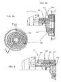
- a pulley variant 500 according to the invention is illustrated in longitudinal section and exploded perspective, by the Figures 5a and 5b , capable of providing two stiffness values for a reversible alternator 16.
- the pulley 500 comprises a rubber ring 502, as a base elastic element disposed between the rim 501 and the hub 503 mounted on the central nut 100, the rim and the hub being separated by a plain bearing 504.
- a clearance limiter 510 consisting of a central plate 512 secured to an outer face of the central hub 503 and elastic stops 514, regularly arranged. on an inner face of the rim 501.
- the stops and the limiter being shaped to come into deforming contact in starting mode. This limiter then brings a excess stiffness in starting mode for alternator torque values substantially greater than, for example, +/- 30 Nm
- the plate 512 of rigid plastic material is substantially square, having contact faces Fc , and the two rubber stops 514 are of substantially triangular shape, having two main faces F p of contact.
- the alternator tends to provide a motor torque that can range from 0 to C3, for example up to 60 Nm, but can also receive a torque of 0 to C4 because of the fluctuations described in the introduction (see Figure 16).
- the angular deformations then sweep the entire range ⁇ 4- ⁇ 3, alternately in motor mode (positively until ⁇ 3) and in receiver mode (negatively until ⁇ 4).
- the sweep is reduced to the basic strain range extending from ⁇ 2 to ⁇ 1, alternately for both receiver (from 0 to ⁇ 2) and motor (from 0 to ⁇ 1) pairs, corresponding globally to the range C2-C1 (for example - 20 to +20 Nm).
- At least one basic decoupler element intervenes and, depending on the direction of the motor or receiver torque, provides stiffnesses K1 (linear portion OA of the diagram) and K2 ( linear portion OB of the diagram), K2 being equal to K1 in the case of a symmetrical decoupler.
- the basic decoupler element, of stiffness K1 or respectively K2 is associated with a travel limiter of stiffness ⁇ K1 or respectively ⁇ K2, to provide a resultant stiffness, respectively K3 (AC portion) and K4 (BD portion), higher absolute values (for example from 2 to 4 Nm / degree).
- the base element is calculated in dimension and material to provide a stiffness value K1 optimized for the pure decoupling phase.
- the Figures 7a to 7d present a pulley variant 700 whose stiffness are differentiated in motor and receiver modes, for the starting speed.
- the figure 7a illustrates a perspective view in which the central plate 712 made of rigid plastic material takes up that of the preceding variant ( figures 5a - 5b) with an elastic decoupling ring and a limiter.
- the resilient stops 714 of the limiter, formed on the inner face of the rim 701, also repeat the configuration of the previous version, but are this time armed with a rigid strand 715 of plastic material.
- the strands are fixed in a channel arranged near a Fp * of the main faces Fp of each stop.
- the sectional view of the figure 7b shows the position of the plate 712 in the free state.
- a vertex S of the plate in this position forms with this vertex S, displaced in positions S1 and S2 corresponding to the plate 712 (in dashed lines) respectively in contact with the faces Fp of the abutments 714 adjacent deformation angles ⁇ 1 and ⁇ 2.
- angles ⁇ 1 and ⁇ 2 define the deformation of the elastic assembly of the pulley in the transition of the start / start regimes, respectively in motor mode, corresponding to the contact of the plate with the face Fp * densified by the proximity of the rigid strand 715 - , and in receiver mode, corresponding to the contact between the plate and the unreinforced face Fp.
- the distribution of the values of the angles ⁇ 1 and ⁇ 2 corresponds to the respective distribution of stiffness K1 and K3 on the one hand, K1 and K4 on the other hand in each deformation range, respectively in motor mode and in receiver.
- the position of the plate in the free state is then preset so that the distribution of the deformation values are optimized with respect to the kinematic characteristics of transmission of torque and decoupling of the system for each of the regimes, starting and started, and for each mode. operating, motor and receiver.
- FIGs 7c and 7d show more precisely the position of contact of the plate 712 to the passage (by rotation according to arrows F1 and F2) start / start regimes, respectively in motor mode ( Figure 7c ), with the contact between the plate 712 and the reinforced face Fp * of the stops 714 -, and in receiver mode ( figure 7d with the contact of the plate 712 and the non-reinforced face Fp of the abutments 714 -.
- FIG. 8a to 8c Another example of a differentially stiffened travel limiter for starting in motor and receiver modes is illustrated by the Figures 8a to 8c .
- This limiter is distinguished from the previous by resilient peripheral stops formed by advances 814 of a peripheral annular blade R, mounted on the rim 801. Part of these advances is stiffened by elastic tongues 815, inserted between the spring R and the rim 801, to define an upper stiffness in motor mode.
- angles ⁇ 'l and ⁇ '2 are preset when the plate 812 is in the free position ( figure 8a ) in order to adapt, as in the previous version, the distribution of deformations as a function of the speed, starting and started, with regard to the kinematic characteristics of torque transmission and decoupling of the system for each of the speeds and for each operating mode: motor mode ( figure 8b ) where the plate 812 is in deforming contact with the advancing portions 814 reinforced by the compressed tabs 815, and receiving mode ( figure 8c ), where the plate 812 is in contact with the non-reinforced advance portions.
- the limiter consists of reinforced elastic stops 914 on the rim 901 of the type of stops illustrated by the Figures 7a to 7d .
- the plate 912 has a pentagonal geometry whose faces bear recesses 912a. These recesses induce a dissymmetry of the deflections, respectively ⁇ "1 and ⁇ ''2, corresponding to the motor and receiver modes in starting mode.
- the stops 924 are an integral part of the rim 902 and are therefore rigid.
- the elasticity of contact of the stops with the circular plate 922 is provided by a rubber coating 932 of the plate 922.
- This coating has advances 934, in the form of a "viper tail", and notches 935.
- a preset of plateau makes it possible to define deflection angles ⁇ "'1 and ⁇ "' 2for motor and receiver modes.
- each advance 934 enters the notch 935 and the contact is transmitted, via the advance 934, between the rigid stop 924 and the rigid plate 922.
- receiver mode reverse rotation according to the arrow F2 in figure 9d
- the advance 934 comes into deforming contact on the one hand against the stop 924 and on the other hand against the coating 932, which has a thickness substantially greater than that left by the depression of the notch 935. Under these conditions, the stiffnesses in receiver and motor modes are substantially differentiated.
- FIG. 10a to 10d Various implementations of the basic elastic element and the travel limiter, constituted by one of the preceding examples, are illustrated by the Figures 10a to 10d according to views in longitudinal section of pulleys, respectively referenced 600a to 600d, mounted on the reversible alternator 10.
- the elastic assemblies are mounted between a rim 601a to 601d and a hub, 603a to 603d, the rim and the hub being assembled on a bearing or bearing 604, more generally on any known load bearing device.
- the travel limiter is formed of a plate 612 and abutments 614, and the base elastic member of a rubber ring 602.
- the travel limiter 612-614 and the elastic ring 602 are disposed at the ends of the pulley, respectively 600a and 600b.
- the limiter 612 - 614 and the ring gear 602 are arranged side by side at the end of the pulley (respectively on the side of the alternator 10 and the side opposite the alternator 10).
- a variant of pulley 600 for a reversible alternator 10 is illustrated in the sectional view of FIG. figure 11 . It consists of a 601 rim and a hub 603 assembled on the load support device 604.
- the pulley comprises two basic elastic rings, 602a and 602b, each associated with a travel limiter, respectively 612a-614a and 612b-614b.
- the freewheel 3b carries only the elastic ring 602b, without the travel limiter 612b-614b.
- the other free wheel 3a directly connects the rim 601 to the hub 603 without limiter or crown.
- variant 600 "of the preceding pulley has a torsion spring 302, protected by a flange 619, in place of the elastic ring 602b.
- the wheels remain mounted in opposition and the elastic member 302 or 602b acts in the direction of the torque in opposition to one or other of the freewheels.
Landscapes
- Engineering & Computer Science (AREA)
- General Engineering & Computer Science (AREA)
- Mechanical Engineering (AREA)
- Physics & Mathematics (AREA)
- Acoustics & Sound (AREA)
- Aviation & Aerospace Engineering (AREA)
- Devices For Conveying Motion By Means Of Endless Flexible Members (AREA)
- Pulleys (AREA)
- Transmission Devices (AREA)
- Connection Of Motors, Electrical Generators, Mechanical Devices, And The Like (AREA)
Claims (13)
- Start-Stopp-Anlasser, welcher von der Kurbelwelle einer Wärmekraftmaschine eines Kraftfahrzeugs separiert ist, welcher in einem angelassenen Regime einen ersten Bereich von Basisdeformationen und in einem Anlassregime einen zweiten Bereich von Deformationen, welcher ausgedehnter ist als der erste Bereich von Basisdeformationen aufweist, und eine Rolle einer Einrichtung zur Kraftübertragung (10, 20) über einen Riemen (1), in dem Anlassregime und dann in dem angelassenen Regime, aufweist, umfassend wenigstens ein elastisches Entkopplungselement (202, 302, 402, 502, 602), welches positioniert ist zwischen einer zentralen Nabe (203, 303, 403, 503) und einem Radkranz (201, 301, 401, 501), auf welchem der Antriebsriemen gespannt ist, und welches mit einem progressiven Auslenkungsbegrenzerelement (510; 610; 710) verbunden ist, dadurch gekennzeichnet, dass der Auslenkungsbegrenzer zwei Bestandteile umfasst, nämlich eine zentrale Platte (512, 612, 712, 812, 912), welche an einer Außenseite der zentralen Nabe befestigt ist, welche gekoppelt ist mit im Umfang regelmäßig an einer Innenseite des Radkranzes angeordneten Anschlägen (514, 614, 714, 814, 914), und in welcher die Entkopplungs- und Auslenkungsbegrenzerelemente eine elastische Gesamtheit bilden, welche zwei Steifigkeitswerte bereitstellt, sei es in einer antreibenden oder einer angetriebenen Phase, nämlich einen ersten Basiswert (K1, K2) der Steifigkeit, welcher erbracht wird durch das aktive elastische Entkopplungselement in dem Anlassregime oder angelassenen Regime in einem zentralen Bereich von positiven und negativen Deformationen für jede Drehmomentrichtung, was dem ersten Bereich von Basisdeformationen entspricht, und an welchen sich in jenseits des zentralen Bereichs angeordneten Intervallen eine zusätzliche Steifigkeit (ΔK1, ΔK2) anfügt, welche durch den Auslenkungsbegrenzer erbracht wird, um eine resultierende Steifigkeit (K3, K4) mit höherem Absolutwert bereitzustellen.
- Start-Stopp-Anlasser nach Anspruch 1, wobei das Entkopplungselement ein Kranz aus einem Elastomer (202), welcher direkt oder über einen Einsatz angehaftet ist, eine Torsionsfeder (302) oder eine Spiralfeder (402) oder wenigstens eines dieser Elemente verbunden mit zwei gegenüberliegend angebrachten freien Rädern (3a, 3b) ist.
- Start-Stopp-Anlasser nach dem vorhergehenden Anspruch, wobei das elastische Material des Kranzes ein Material vom Kautschuktyp ist, welches ausgewählt ist aus Silikon, einem HNBR, Chloropren, einem EPDM, einem BR, einem NR und einer Kombination von wenigstens zwei dieser Verbindungen.
- Start-Stopp-Anlasser nach einem der vorhergehenden Ansprüche, wobei die zentrale Platte in Form eines regelmäßigen Polygons (712), vorzugsweise mit vier Seiten, ist und die winkeligen Anschläge (714) aus einem elastischen Material, welches zwei Hauptkontaktflächen (Fp) aufweist, sind.
- Start-Stopp-Anlasser nach einem der Ansprüche 1-3, wobei die zentrale Platte ringförmig (922) ist und eine Umfangsschicht aus einem elastischen Material aufweist, welche Vorsprünge (933, 934) ausbildet, welche in Kontakt mit Umfangsanschlägen (714, 924) kommen.
- Start-Stopp-Anlasser nach einem der Ansprüche 1-3, wobei die Anschläge ausgebildet sind ausgehend von einer Umfangsblattfeder (R), welche an dem Radkranz angebracht ist und regelmäßig verteilte zentripetale Vorsprünge (814) aufweist.
- Start-Stopp-Anlasser nach einem der Ansprüche 1-6, wobei die Auslenkungsbegrenzer durch das Vorhandensein von winkeligen Anschlägen (714, 814) asymmetrisch gemacht sind und/oder Vorsprünge (933, 934) der ringförmigen Platte einen Unterschied in Dichte, Modul oder Form entlang der Kontaktfläche aufweisen, sodass die gemäß der Fläche (Fp, Fp*) erhaltenen Kontakte Steifigkeiten definieren, welche an die entsprechende Drehmomentrichtung angepasst sind, wobei eine angepasste Kombination von zwei spezifischen Steifigkeiten für jede Drehmomentrichtung zum Einsatz gebracht wird, welche durch die Verbindung des spezifischen elastischen Basiselements und des asymmetrischen Auslenkungsbegrenzers erhalten wird.
- Start-Stopp-Anlasser nach Anspruch 7, wobei eine elastische Entkopplungsanordnung mit optimierter Verteilung von Steifigkeitszuständen entsprechend dem Anlassregime und angelassenen Regime für jede Drehmomentrichtung realisiert ist durch die Regelung der Position der Vorsprünge der Platte im freien Zustand, welche mit dem entsprechenden Kontaktanschlag im antreibenden Modus oder angetriebenen Modus dieser Vorsprünge einen voreingestellten Schwellwinkel (Θ1, Θ2) zum Wechsel des Anlassregimes/angelassenen Regimes bildet.
- Start-Stopp-Anlasser nach Anspruch 7 oder 8, wobei jeder Anschlag gebildet ist durch zwei Halbanschläge aus Materialien, welche unterschiedliche Dichten aufweisen.
- Start-Stopp-Anlasser nach Anspruch 8 oder 9, wobei jeder Anschlag eine Litze (715) aus einem starren Material oder mit einer höheren Dichte als das elastische Material des Rests des Anschlags aufweist, wobei die Litze näher an einer Kontaktfläche als an der anderen angeordnet ist.
- Start-Stopp-Anlasser nach Anspruch 7 oder 8, wobei eine Zunge aus einem elastischen Material (815) zwischen den Radkranz und einen Teil eines Anschlags in Form eines Vorsprungs einer ringförmigen Blattfeder eingefügt ist.
- Start-Stopp-Anlasser nach einem der vorhergehenden Ansprüche, wobei, um auch die Steifigkeiten der angelassenen Regimes im antreibenden und angetriebenen Modus zu differenzieren, die Entkopplung realisiert ist über zwei elastische Basisentkopplungselemente mit unterschiedlicher Steifigkeit (602a, 602b), wobei wenigstens eines dieser Elemente mit einem Auslenkungsbegrenzer (612a, 614a; 612b, 614b) verbunden ist, dessen Steifigkeit gemäß dem Modus angepasst ist, und jeder Verbund an einem freien Rad (3a, 3b) angebracht ist, wobei die zwei freien Räder auf solche Weise gegenüberliegend sind, dass ein an jede Richtung angepasster Steifigkeitswert definiert wird.
- Start-Stopp-Anlasser nach den vorhergehenden Ansprüchen, dadurch gekennzeichnet, dass der Bereich von Basisverformungen Drehmomenten entspricht, welche zwischen -20 Nm und +20 Nm enthalten sind.
Applications Claiming Priority (1)
| Application Number | Priority Date | Filing Date | Title |
|---|---|---|---|
| FR0412479A FR2878305B1 (fr) | 2004-11-24 | 2004-11-24 | Poulie d'organe de transmission de puissance, alterno-demarreur separe equipe d'une telle poulie et systeme d'entrainement de moteur thermique |
Publications (2)
| Publication Number | Publication Date |
|---|---|
| EP1662161A1 EP1662161A1 (de) | 2006-05-31 |
| EP1662161B1 true EP1662161B1 (de) | 2011-03-23 |
Family
ID=34954440
Family Applications (1)
| Application Number | Title | Priority Date | Filing Date |
|---|---|---|---|
| EP05292358A Not-in-force EP1662161B1 (de) | 2004-11-24 | 2005-11-08 | Riemenscheibe zur Kraftübertragung, Starter-Generator ausgerüstet mit so einer Riemenscheibe und Antriebssystem eines Verbrennungsmotors |
Country Status (7)
| Country | Link |
|---|---|
| US (1) | US7985150B2 (de) |
| EP (1) | EP1662161B1 (de) |
| JP (1) | JP4641931B2 (de) |
| AT (1) | ATE503125T1 (de) |
| DE (1) | DE602005027035D1 (de) |
| ES (1) | ES2363776T3 (de) |
| FR (1) | FR2878305B1 (de) |
Families Citing this family (43)
| Publication number | Priority date | Publication date | Assignee | Title |
|---|---|---|---|---|
| KR101565168B1 (ko) * | 2006-07-07 | 2015-11-02 | 데이코 유로페 에스.알.엘. 콘 유니코 소시오 | 풀리 어셈블리 |
| EP2041451B1 (de) * | 2006-07-07 | 2011-02-16 | DAYCO EUROPE S.r.l. | Riemenscheibenanorndung |
| BRPI0621782A2 (pt) | 2006-07-07 | 2011-12-20 | Dayco Europe Srl | montagem de polia |
| DE112007002872B4 (de) * | 2006-12-06 | 2017-01-26 | Schaeffler Technologies AG & Co. KG | Triebrad eines Nebenaggregatezugs eines Verbrennungsmotors |
| US8632431B2 (en) | 2006-12-11 | 2014-01-21 | Schaeffler Technologies AG & Co. KG | Drive wheel of an auxiliary unit belt drive of an internal combustion engine |
| EP2088327B1 (de) * | 2008-02-11 | 2011-08-31 | Agilent Technologies Italia S.p.A. | Stütze für Wälzlager |
| DE102008023177B4 (de) * | 2008-05-10 | 2019-06-27 | Dr. Ing. H.C. F. Porsche Aktiengesellschaft | Antriebseinrichtung für wenigstens eine Maschinenhilfseinheit mittels eines Riemens |
| US8888619B2 (en) * | 2008-10-27 | 2014-11-18 | Litens Automotive Partnership | Over-running decoupler with torque limiter |
| JP2011122566A (ja) * | 2009-12-14 | 2011-06-23 | Isuzu Motors Ltd | エンジンの振動低減装置 |
| WO2011143580A2 (en) * | 2010-05-14 | 2011-11-17 | Connard Cali | Overrunning isolating decoupler pulleys |
| JP2012049838A (ja) * | 2010-08-27 | 2012-03-08 | Elpida Memory Inc | 半導体装置およびその特性調整方法 |
| DE202010012227U1 (de) * | 2010-09-06 | 2010-12-23 | Hackforth Gmbh | Drehelastische Wellenkupplung |
| US20120322592A1 (en) * | 2011-04-11 | 2012-12-20 | Zen Sa Industria Metalurgica | Overrunning pulley with elastomer torsional damping system |
| JP2012225264A (ja) * | 2011-04-20 | 2012-11-15 | Isuzu Motors Ltd | エンジンの振動低減装置 |
| US20130059685A1 (en) * | 2011-09-07 | 2013-03-07 | Connard Cali | Self-lubricating torque transfer devices |
| WO2013049919A1 (en) | 2011-10-06 | 2013-04-11 | Litens Automotive Partnership | Clutched driven device and associated clutch mechanism |
| WO2013152430A1 (en) | 2012-04-10 | 2013-10-17 | Litens Automotive Partnership | Clutch assembly |
| CN104541080A (zh) * | 2012-06-20 | 2015-04-22 | 戴科知识产权控股有限责任公司 | 附件驱动分离器 |
| DE102013210428A1 (de) | 2012-07-05 | 2014-01-09 | Schaeffler Technologies AG & Co. KG | Antriebsstrang mit Zweimassenschwungrad |
| US20150285312A1 (en) * | 2012-10-12 | 2015-10-08 | Litens Automotive Partnership | Isolator for use with mgu that is used to assist or start engine through and endless drive member |
| CN104822965B (zh) | 2012-10-12 | 2017-11-28 | 利滕斯汽车合伙公司 | 通过环形传动构件由mgu或马达辅助或起动的发动机所使用的隔离器 |
| DE102012024958A1 (de) * | 2012-12-20 | 2014-07-10 | GM Global Technology Operations LLC (n. d. Ges. d. Staates Delaware) | Riemenscheibe für eine Kurbelwelle in einem Fahrzeug |
| US9872438B2 (en) * | 2013-03-15 | 2018-01-23 | Mtd Products Inc | Battery-electric and internal-combustion engine assist hybrid propulsion and implement drive work systems |
| CN105102839B (zh) | 2013-04-10 | 2018-06-12 | 利滕斯汽车合伙公司 | 离合器组件 |
| US9797498B2 (en) | 2013-05-23 | 2017-10-24 | Litens Automotive Partnership | Isolator with double acting spring system with reduced noise |
| US10267405B2 (en) | 2013-07-24 | 2019-04-23 | Litens Automotive Partnership | Isolator with improved damping structure |
| EP3025072B1 (de) | 2013-07-25 | 2018-12-26 | Litens Automotive Partnership | Federanordnung für einen isolator |
| ITTO20130677A1 (it) | 2013-08-06 | 2015-02-07 | Dayco Europe Srl | Puleggia filtrante per una trasmissione a cinghia |
| KR101490948B1 (ko) * | 2013-09-09 | 2015-02-12 | 현대자동차 주식회사 | 차량용 댐퍼 풀리 조립체 |
| EP3066354B1 (de) | 2013-11-10 | 2018-12-26 | Litens Automotive Partnership | Isolator mit doppelfedern |
| JP6256013B2 (ja) * | 2014-01-09 | 2018-01-10 | 株式会社ジェイテクト | プーリユニット |
| FR3022005B1 (fr) * | 2014-06-06 | 2016-07-08 | Vianney Rabhi | Raccord d'etancheite tournant haute-pression a bague continue extensible |
| TWI551795B (zh) * | 2014-07-14 | 2016-10-01 | 勝利工業股份有限公司 | 用於交流發電機之皮帶輪 |
| TWI555932B (zh) * | 2014-07-14 | 2016-11-01 | 勝利工業股份有限公司 | 用於交流發電機之皮帶輪 |
| CN104100695A (zh) * | 2014-07-24 | 2014-10-15 | 苏州淮通电气有限公司 | 一种易拆装三角带的电机飞轮 |
| US9341254B2 (en) * | 2014-08-08 | 2016-05-17 | Gates Corporation | Isolating pulley |
| DE102014117543A1 (de) * | 2014-11-28 | 2016-06-16 | Trelleborgvibracoustic Gmbh | Schwingungsdämpfungsvorrichtung |
| US9291253B1 (en) * | 2015-03-24 | 2016-03-22 | Gates Corporation | Isolating decoupler |
| FR3053394B1 (fr) * | 2016-06-30 | 2019-08-09 | Hutchinson | Poulie de decouplage a embrayage deporte |
| DE102017003156A1 (de) * | 2017-03-31 | 2018-10-04 | Süddeutsche Gelenkscheibenfabrik GmbH & Co. KG | Schwingungsentkoppelte Riemenscheibe |
| FR3073267B1 (fr) * | 2017-11-08 | 2019-11-01 | Hutchinson | Poulie pour alterno-demarreur |
| WO2020191495A1 (en) | 2019-03-26 | 2020-10-01 | Litens Automotive Partnership | Rotary device with clutch with time-based slip and method of providing time-based slip for a rotary device |
| US11796046B2 (en) * | 2021-01-08 | 2023-10-24 | American Axle & Manufacturing, Inc. | Isolated drive assembly with an isolator assembly and a torque limiter for limiting the transmission of torque through an elastomeric element of the isolator assembly |
Citations (1)
| Publication number | Priority date | Publication date | Assignee | Title |
|---|---|---|---|---|
| US20040014540A1 (en) * | 2002-04-18 | 2004-01-22 | Dell James W. | Isolator for alternator pulley |
Family Cites Families (21)
| Publication number | Priority date | Publication date | Assignee | Title |
|---|---|---|---|---|
| US4328879A (en) * | 1978-04-27 | 1982-05-11 | The Gates Rubber Company | Shock-absorbing sprocket, drive assembly, and the like |
| FR2443621A1 (fr) * | 1978-12-06 | 1980-07-04 | Citroen Sa | Dispositif d'entrainement par poulie |
| ES480783A1 (es) * | 1979-05-09 | 1980-01-16 | Damper Iberica Sa | Perfeccionamientos en los mecanismos para el acoplamiento - elastico de un eje motor con uneje conducido. |
| US4486183A (en) * | 1980-06-30 | 1984-12-04 | The Gates Rubber Company | Torsionally elastic power transmitting device and drive |
| JPH0511757Y2 (de) * | 1986-09-25 | 1993-03-24 | ||
| JPH0533813Y2 (de) * | 1987-09-30 | 1993-08-27 | ||
| US5139463A (en) | 1991-06-05 | 1992-08-18 | Litens Automotive Partnership | Serpentine drive with coil spring alternator connection |
| DE4201049C2 (de) * | 1992-01-17 | 1995-11-02 | Freudenberg Carl Fa | Drehzahladaptiver Drehschwingungsdämpfer |
| JP2599818Y2 (ja) * | 1992-11-30 | 1999-09-20 | エヌ・オー・ケー・メグラスティック株式会社 | カップリング |
| DE9304497U1 (de) * | 1993-03-26 | 1993-05-13 | Centa-Antriebe Kirschey GmbH, 5657 Haan | Wellenkupplung |
| JP2779331B2 (ja) | 1995-03-08 | 1998-07-23 | バンドー化学株式会社 | エンジン用補機のベルト伝動装置 |
| FR2734034B1 (fr) * | 1995-05-12 | 1997-07-11 | Hutchinson | Dispositif de decouplage, notamment poulie decoupleuse, destine a un vehicule automobile |
| JP3671571B2 (ja) * | 1996-02-29 | 2005-07-13 | 株式会社デンソー | 動力伝達装置 |
| JP3556800B2 (ja) | 1997-04-09 | 2004-08-25 | 光洋精工株式会社 | オルタネータプーリ |
| CZ298343B6 (cs) | 1997-05-07 | 2007-08-29 | Litens Automotive Partnership | Zarízení k prenosu pohybu remene a serpentinový remenový pohonný systém |
| JP2000240461A (ja) | 1999-02-23 | 2000-09-05 | Nsk Ltd | オルタネータ用一方向クラッチ内蔵型プーリ装置とオルタネータ駆動用無端ベルトの鳴き防止方法 |
| JP2001343024A (ja) * | 2000-03-29 | 2001-12-14 | Toyota Industries Corp | 動力伝達機構 |
| GB0109706D0 (en) * | 2001-04-20 | 2001-06-13 | Metaldyne Internat Uk Ltd | A torsional isolation device for isolating torque fluctuations |
| JP3915486B2 (ja) * | 2001-11-26 | 2007-05-16 | 株式会社デンソー | トルク伝達装置 |
| US6786316B2 (en) * | 2002-07-01 | 2004-09-07 | Ntn Corporation | Electro-magnetic clutch pulley |
| FR2853373B1 (fr) * | 2003-04-02 | 2006-03-03 | Hutchinson | Element de decouplage en materiau deformable dans un systeme de transmission de puissance |
-
2004
- 2004-11-24 FR FR0412479A patent/FR2878305B1/fr not_active Expired - Fee Related
-
2005
- 2005-11-08 EP EP05292358A patent/EP1662161B1/de not_active Not-in-force
- 2005-11-08 AT AT05292358T patent/ATE503125T1/de not_active IP Right Cessation
- 2005-11-08 DE DE602005027035T patent/DE602005027035D1/de active Active
- 2005-11-08 ES ES05292358T patent/ES2363776T3/es active Active
- 2005-11-18 US US11/281,486 patent/US7985150B2/en not_active Expired - Fee Related
- 2005-11-22 JP JP2005336518A patent/JP4641931B2/ja not_active Expired - Fee Related
Patent Citations (1)
| Publication number | Priority date | Publication date | Assignee | Title |
|---|---|---|---|---|
| US20040014540A1 (en) * | 2002-04-18 | 2004-01-22 | Dell James W. | Isolator for alternator pulley |
Also Published As
| Publication number | Publication date |
|---|---|
| FR2878305B1 (fr) | 2008-05-30 |
| US7985150B2 (en) | 2011-07-26 |
| ES2363776T3 (es) | 2011-08-16 |
| JP4641931B2 (ja) | 2011-03-02 |
| FR2878305A1 (fr) | 2006-05-26 |
| EP1662161A1 (de) | 2006-05-31 |
| US20060122014A1 (en) | 2006-06-08 |
| DE602005027035D1 (de) | 2011-05-05 |
| JP2006177548A (ja) | 2006-07-06 |
| ATE503125T1 (de) | 2011-04-15 |
Similar Documents
| Publication | Publication Date | Title |
|---|---|---|
| EP1662161B1 (de) | Riemenscheibe zur Kraftübertragung, Starter-Generator ausgerüstet mit so einer Riemenscheibe und Antriebssystem eines Verbrennungsmotors | |
| EP1764524B1 (de) | Riemenscheibenantrieb | |
| EP2935935B1 (de) | Schwingungsdämpfer für eine drehmomentübertragungsvorrichtung eines kraftfahrzeugs | |
| EP2383490B1 (de) | Entkupplungsriemenscheibe | |
| FR2749365A1 (fr) | Amortisseur d'oscillations en torsion | |
| FR2876760A1 (fr) | Dispositif de transmission de puissance | |
| CN103765027A (zh) | 隔离断开器 | |
| EP1651878B1 (de) | Freilauflagervorrichtung mit drehmomentbegrenzer | |
| FR2822211A1 (fr) | Amortisseur d'oscillations de rotation | |
| FR2710710A1 (fr) | Amortisseur d'oscillations en torsion. | |
| EP2459901A2 (de) | Steuerbares hydraulisches spannschloss | |
| EP3707412B1 (de) | Riemenscheibe für einen starter-generator | |
| EP1977143B1 (de) | Kurbelwellenscheibe | |
| FR2865010A1 (fr) | Embrayage a friction, notamment pour vehicule automobile, comportant des moyens de frottement differencies | |
| EP0762000B1 (de) | Verbindungs- und Kraftübertragungsvorrichtung zwischen zwei koaxialen drehenden Teilen | |
| FR2933460A1 (fr) | Dispositif de poulie debrayable | |
| EP3483470B1 (de) | Reibungsvorrichtung einer kupplung | |
| WO2019053267A1 (fr) | Dispositif de transmission de couple, amortisseur de torsion et assemblage associe | |
| FR2939855A1 (fr) | Roue libre pour dispositif de poulie debrayable | |
| FR3130339A1 (fr) | Moyen d’étanchéité pour Double volant amortisseur | |
| WO2018100112A1 (fr) | Dispositif de phasage pour amortisseur d'embrayage a friction et embrayage a friction comportant un tel dispositif | |
| FR3083275A1 (fr) | Dispositif de transmission de couple et disque d'embrayage comprenant un tel dispositif |
Legal Events
| Date | Code | Title | Description |
|---|---|---|---|
| PUAI | Public reference made under article 153(3) epc to a published international application that has entered the european phase |
Free format text: ORIGINAL CODE: 0009012 |
|
| AK | Designated contracting states |
Kind code of ref document: A1 Designated state(s): AT BE BG CH CY CZ DE DK EE ES FI FR GB GR HU IE IS IT LI LT LU LV MC NL PL PT RO SE SI SK TR |
|
| AX | Request for extension of the european patent |
Extension state: AL BA HR MK YU |
|
| 17P | Request for examination filed |
Effective date: 20061019 |
|
| 17Q | First examination report despatched |
Effective date: 20061120 |
|
| AKX | Designation fees paid |
Designated state(s): AT BE BG CH CY CZ DE DK EE ES FI FR GB GR HU IE IS IT LI LT LU LV MC NL PL PT RO SE SI SK TR |
|
| GRAP | Despatch of communication of intention to grant a patent |
Free format text: ORIGINAL CODE: EPIDOSNIGR1 |
|
| GRAS | Grant fee paid |
Free format text: ORIGINAL CODE: EPIDOSNIGR3 |
|
| GRAA | (expected) grant |
Free format text: ORIGINAL CODE: 0009210 |
|
| AK | Designated contracting states |
Kind code of ref document: B1 Designated state(s): AT BE BG CH CY CZ DE DK EE ES FI FR GB GR HU IE IS IT LI LT LU LV MC NL PL PT RO SE SI SK TR |
|
| REG | Reference to a national code |
Ref country code: GB Ref legal event code: FG4D Free format text: NOT ENGLISH |
|
| REG | Reference to a national code |
Ref country code: CH Ref legal event code: EP |
|
| REG | Reference to a national code |
Ref country code: IE Ref legal event code: FG4D |
|
| REF | Corresponds to: |
Ref document number: 602005027035 Country of ref document: DE Date of ref document: 20110505 Kind code of ref document: P |
|
| REG | Reference to a national code |
Ref country code: DE Ref legal event code: R096 Ref document number: 602005027035 Country of ref document: DE Effective date: 20110505 |
|
| REG | Reference to a national code |
Ref country code: NL Ref legal event code: VDEP Effective date: 20110323 |
|
| PG25 | Lapsed in a contracting state [announced via postgrant information from national office to epo] |
Ref country code: SE Free format text: LAPSE BECAUSE OF FAILURE TO SUBMIT A TRANSLATION OF THE DESCRIPTION OR TO PAY THE FEE WITHIN THE PRESCRIBED TIME-LIMIT Effective date: 20110323 Ref country code: LT Free format text: LAPSE BECAUSE OF FAILURE TO SUBMIT A TRANSLATION OF THE DESCRIPTION OR TO PAY THE FEE WITHIN THE PRESCRIBED TIME-LIMIT Effective date: 20110323 Ref country code: LV Free format text: LAPSE BECAUSE OF FAILURE TO SUBMIT A TRANSLATION OF THE DESCRIPTION OR TO PAY THE FEE WITHIN THE PRESCRIBED TIME-LIMIT Effective date: 20110323 Ref country code: GR Free format text: LAPSE BECAUSE OF FAILURE TO SUBMIT A TRANSLATION OF THE DESCRIPTION OR TO PAY THE FEE WITHIN THE PRESCRIBED TIME-LIMIT Effective date: 20110624 |
|
| REG | Reference to a national code |
Ref country code: ES Ref legal event code: FG2A Ref document number: 2363776 Country of ref document: ES Kind code of ref document: T3 Effective date: 20110816 |
|
| LTIE | Lt: invalidation of european patent or patent extension |
Effective date: 20110323 |
|
| PG25 | Lapsed in a contracting state [announced via postgrant information from national office to epo] |
Ref country code: AT Free format text: LAPSE BECAUSE OF FAILURE TO SUBMIT A TRANSLATION OF THE DESCRIPTION OR TO PAY THE FEE WITHIN THE PRESCRIBED TIME-LIMIT Effective date: 20110323 Ref country code: FI Free format text: LAPSE BECAUSE OF FAILURE TO SUBMIT A TRANSLATION OF THE DESCRIPTION OR TO PAY THE FEE WITHIN THE PRESCRIBED TIME-LIMIT Effective date: 20110323 Ref country code: BG Free format text: LAPSE BECAUSE OF FAILURE TO SUBMIT A TRANSLATION OF THE DESCRIPTION OR TO PAY THE FEE WITHIN THE PRESCRIBED TIME-LIMIT Effective date: 20110623 Ref country code: CY Free format text: LAPSE BECAUSE OF FAILURE TO SUBMIT A TRANSLATION OF THE DESCRIPTION OR TO PAY THE FEE WITHIN THE PRESCRIBED TIME-LIMIT Effective date: 20110323 Ref country code: SI Free format text: LAPSE BECAUSE OF FAILURE TO SUBMIT A TRANSLATION OF THE DESCRIPTION OR TO PAY THE FEE WITHIN THE PRESCRIBED TIME-LIMIT Effective date: 20110323 |
|
| REG | Reference to a national code |
Ref country code: IE Ref legal event code: FD4D |
|
| PG25 | Lapsed in a contracting state [announced via postgrant information from national office to epo] |
Ref country code: EE Free format text: LAPSE BECAUSE OF FAILURE TO SUBMIT A TRANSLATION OF THE DESCRIPTION OR TO PAY THE FEE WITHIN THE PRESCRIBED TIME-LIMIT Effective date: 20110323 Ref country code: PT Free format text: LAPSE BECAUSE OF FAILURE TO SUBMIT A TRANSLATION OF THE DESCRIPTION OR TO PAY THE FEE WITHIN THE PRESCRIBED TIME-LIMIT Effective date: 20110725 |
|
| PG25 | Lapsed in a contracting state [announced via postgrant information from national office to epo] |
Ref country code: IS Free format text: LAPSE BECAUSE OF FAILURE TO SUBMIT A TRANSLATION OF THE DESCRIPTION OR TO PAY THE FEE WITHIN THE PRESCRIBED TIME-LIMIT Effective date: 20110723 Ref country code: CZ Free format text: LAPSE BECAUSE OF FAILURE TO SUBMIT A TRANSLATION OF THE DESCRIPTION OR TO PAY THE FEE WITHIN THE PRESCRIBED TIME-LIMIT Effective date: 20110323 Ref country code: RO Free format text: LAPSE BECAUSE OF FAILURE TO SUBMIT A TRANSLATION OF THE DESCRIPTION OR TO PAY THE FEE WITHIN THE PRESCRIBED TIME-LIMIT Effective date: 20110323 Ref country code: SK Free format text: LAPSE BECAUSE OF FAILURE TO SUBMIT A TRANSLATION OF THE DESCRIPTION OR TO PAY THE FEE WITHIN THE PRESCRIBED TIME-LIMIT Effective date: 20110323 |
|
| PG25 | Lapsed in a contracting state [announced via postgrant information from national office to epo] |
Ref country code: NL Free format text: LAPSE BECAUSE OF FAILURE TO SUBMIT A TRANSLATION OF THE DESCRIPTION OR TO PAY THE FEE WITHIN THE PRESCRIBED TIME-LIMIT Effective date: 20110323 |
|
| PLBE | No opposition filed within time limit |
Free format text: ORIGINAL CODE: 0009261 |
|
| STAA | Information on the status of an ep patent application or granted ep patent |
Free format text: STATUS: NO OPPOSITION FILED WITHIN TIME LIMIT |
|
| PG25 | Lapsed in a contracting state [announced via postgrant information from national office to epo] |
Ref country code: IE Free format text: LAPSE BECAUSE OF FAILURE TO SUBMIT A TRANSLATION OF THE DESCRIPTION OR TO PAY THE FEE WITHIN THE PRESCRIBED TIME-LIMIT Effective date: 20110323 |
|
| PGFP | Annual fee paid to national office [announced via postgrant information from national office to epo] |
Ref country code: ES Payment date: 20111010 Year of fee payment: 7 |
|
| 26N | No opposition filed |
Effective date: 20111227 |
|
| PG25 | Lapsed in a contracting state [announced via postgrant information from national office to epo] |
Ref country code: PL Free format text: LAPSE BECAUSE OF FAILURE TO SUBMIT A TRANSLATION OF THE DESCRIPTION OR TO PAY THE FEE WITHIN THE PRESCRIBED TIME-LIMIT Effective date: 20110323 Ref country code: DK Free format text: LAPSE BECAUSE OF FAILURE TO SUBMIT A TRANSLATION OF THE DESCRIPTION OR TO PAY THE FEE WITHIN THE PRESCRIBED TIME-LIMIT Effective date: 20110323 |
|
| REG | Reference to a national code |
Ref country code: DE Ref legal event code: R097 Ref document number: 602005027035 Country of ref document: DE Effective date: 20111227 |
|
| BERE | Be: lapsed |
Owner name: HUTCHINSON Effective date: 20111130 |
|
| PG25 | Lapsed in a contracting state [announced via postgrant information from national office to epo] |
Ref country code: MC Free format text: LAPSE BECAUSE OF NON-PAYMENT OF DUE FEES Effective date: 20111130 |
|
| REG | Reference to a national code |
Ref country code: CH Ref legal event code: PL |
|
| PG25 | Lapsed in a contracting state [announced via postgrant information from national office to epo] |
Ref country code: LI Free format text: LAPSE BECAUSE OF NON-PAYMENT OF DUE FEES Effective date: 20111130 Ref country code: CH Free format text: LAPSE BECAUSE OF NON-PAYMENT OF DUE FEES Effective date: 20111130 |
|
| PG25 | Lapsed in a contracting state [announced via postgrant information from national office to epo] |
Ref country code: BE Free format text: LAPSE BECAUSE OF NON-PAYMENT OF DUE FEES Effective date: 20111130 |
|
| PG25 | Lapsed in a contracting state [announced via postgrant information from national office to epo] |
Ref country code: LU Free format text: LAPSE BECAUSE OF NON-PAYMENT OF DUE FEES Effective date: 20111108 |
|
| GBPC | Gb: european patent ceased through non-payment of renewal fee |
Effective date: 20121108 |
|
| PG25 | Lapsed in a contracting state [announced via postgrant information from national office to epo] |
Ref country code: TR Free format text: LAPSE BECAUSE OF FAILURE TO SUBMIT A TRANSLATION OF THE DESCRIPTION OR TO PAY THE FEE WITHIN THE PRESCRIBED TIME-LIMIT Effective date: 20110323 |
|
| PG25 | Lapsed in a contracting state [announced via postgrant information from national office to epo] |
Ref country code: HU Free format text: LAPSE BECAUSE OF FAILURE TO SUBMIT A TRANSLATION OF THE DESCRIPTION OR TO PAY THE FEE WITHIN THE PRESCRIBED TIME-LIMIT Effective date: 20110323 |
|
| PG25 | Lapsed in a contracting state [announced via postgrant information from national office to epo] |
Ref country code: GB Free format text: LAPSE BECAUSE OF NON-PAYMENT OF DUE FEES Effective date: 20121108 |
|
| REG | Reference to a national code |
Ref country code: ES Ref legal event code: FD2A Effective date: 20140305 |
|
| PG25 | Lapsed in a contracting state [announced via postgrant information from national office to epo] |
Ref country code: ES Free format text: LAPSE BECAUSE OF NON-PAYMENT OF DUE FEES Effective date: 20121109 |
|
| REG | Reference to a national code |
Ref country code: FR Ref legal event code: PLFP Year of fee payment: 11 |
|
| REG | Reference to a national code |
Ref country code: FR Ref legal event code: PLFP Year of fee payment: 12 |
|
| REG | Reference to a national code |
Ref country code: FR Ref legal event code: PLFP Year of fee payment: 13 |
|
| REG | Reference to a national code |
Ref country code: FR Ref legal event code: PLFP Year of fee payment: 14 |
|
| PGFP | Annual fee paid to national office [announced via postgrant information from national office to epo] |
Ref country code: DE Payment date: 20191121 Year of fee payment: 15 |
|
| PGFP | Annual fee paid to national office [announced via postgrant information from national office to epo] |
Ref country code: FR Payment date: 20191017 Year of fee payment: 15 Ref country code: IT Payment date: 20191128 Year of fee payment: 15 |
|
| REG | Reference to a national code |
Ref country code: DE Ref legal event code: R119 Ref document number: 602005027035 Country of ref document: DE |
|
| PG25 | Lapsed in a contracting state [announced via postgrant information from national office to epo] |
Ref country code: FR Free format text: LAPSE BECAUSE OF NON-PAYMENT OF DUE FEES Effective date: 20201130 Ref country code: IT Free format text: LAPSE BECAUSE OF NON-PAYMENT OF DUE FEES Effective date: 20201108 |
|
| PG25 | Lapsed in a contracting state [announced via postgrant information from national office to epo] |
Ref country code: DE Free format text: LAPSE BECAUSE OF NON-PAYMENT OF DUE FEES Effective date: 20210601 |