EP1651878B1 - Freilauflagervorrichtung mit drehmomentbegrenzer - Google Patents
Freilauflagervorrichtung mit drehmomentbegrenzer Download PDFInfo
- Publication number
- EP1651878B1 EP1651878B1 EP04767457A EP04767457A EP1651878B1 EP 1651878 B1 EP1651878 B1 EP 1651878B1 EP 04767457 A EP04767457 A EP 04767457A EP 04767457 A EP04767457 A EP 04767457A EP 1651878 B1 EP1651878 B1 EP 1651878B1
- Authority
- EP
- European Patent Office
- Prior art keywords
- friction
- torque limiter
- ring
- limiter member
- torque
- Prior art date
- Legal status (The legal status is an assumption and is not a legal conclusion. Google has not performed a legal analysis and makes no representation as to the accuracy of the status listed.)
- Expired - Lifetime
Links
- 238000005096 rolling process Methods 0.000 claims description 21
- 229920002994 synthetic fiber Polymers 0.000 claims description 5
- 210000002105 tongue Anatomy 0.000 claims description 3
- 229910000831 Steel Inorganic materials 0.000 claims description 2
- 230000005540 biological transmission Effects 0.000 claims description 2
- 239000010959 steel Substances 0.000 claims description 2
- 239000007787 solid Substances 0.000 description 11
- 239000000463 material Substances 0.000 description 4
- 238000005304 joining Methods 0.000 description 2
- 239000002184 metal Substances 0.000 description 2
- 238000011144 upstream manufacturing Methods 0.000 description 2
- 238000004026 adhesive bonding Methods 0.000 description 1
- 230000004323 axial length Effects 0.000 description 1
- 230000009286 beneficial effect Effects 0.000 description 1
- 239000011248 coating agent Substances 0.000 description 1
- 238000000576 coating method Methods 0.000 description 1
- 239000000470 constituent Substances 0.000 description 1
- 238000005260 corrosion Methods 0.000 description 1
- 238000001914 filtration Methods 0.000 description 1
- 239000004519 grease Substances 0.000 description 1
- 230000001050 lubricating effect Effects 0.000 description 1
- 238000004519 manufacturing process Methods 0.000 description 1
- 238000003825 pressing Methods 0.000 description 1
- 239000007858 starting material Substances 0.000 description 1
Images


Classifications
-
- F—MECHANICAL ENGINEERING; LIGHTING; HEATING; WEAPONS; BLASTING
- F16—ENGINEERING ELEMENTS AND UNITS; GENERAL MEASURES FOR PRODUCING AND MAINTAINING EFFECTIVE FUNCTIONING OF MACHINES OR INSTALLATIONS; THERMAL INSULATION IN GENERAL
- F16D—COUPLINGS FOR TRANSMITTING ROTATION; CLUTCHES; BRAKES
- F16D43/00—Automatic clutches
- F16D43/02—Automatic clutches actuated entirely mechanically
- F16D43/20—Automatic clutches actuated entirely mechanically controlled by torque, e.g. overload-release clutches, slip-clutches with means by which torque varies the clutching pressure
- F16D43/21—Automatic clutches actuated entirely mechanically controlled by torque, e.g. overload-release clutches, slip-clutches with means by which torque varies the clutching pressure with friction members
- F16D43/211—Automatic clutches actuated entirely mechanically controlled by torque, e.g. overload-release clutches, slip-clutches with means by which torque varies the clutching pressure with friction members with radially applied torque-limiting friction surfaces
-
- F—MECHANICAL ENGINEERING; LIGHTING; HEATING; WEAPONS; BLASTING
- F16—ENGINEERING ELEMENTS AND UNITS; GENERAL MEASURES FOR PRODUCING AND MAINTAINING EFFECTIVE FUNCTIONING OF MACHINES OR INSTALLATIONS; THERMAL INSULATION IN GENERAL
- F16D—COUPLINGS FOR TRANSMITTING ROTATION; CLUTCHES; BRAKES
- F16D41/00—Freewheels or freewheel clutches
- F16D41/06—Freewheels or freewheel clutches with intermediate wedging coupling members between an inner and an outer surface
- F16D41/069—Freewheels or freewheel clutches with intermediate wedging coupling members between an inner and an outer surface the intermediate members wedging by pivoting or rocking, e.g. sprags
- F16D41/07—Freewheels or freewheel clutches with intermediate wedging coupling members between an inner and an outer surface the intermediate members wedging by pivoting or rocking, e.g. sprags between two cylindrical surfaces
-
- F—MECHANICAL ENGINEERING; LIGHTING; HEATING; WEAPONS; BLASTING
- F16—ENGINEERING ELEMENTS AND UNITS; GENERAL MEASURES FOR PRODUCING AND MAINTAINING EFFECTIVE FUNCTIONING OF MACHINES OR INSTALLATIONS; THERMAL INSULATION IN GENERAL
- F16D—COUPLINGS FOR TRANSMITTING ROTATION; CLUTCHES; BRAKES
- F16D41/00—Freewheels or freewheel clutches
- F16D41/20—Freewheels or freewheel clutches with expandable or contractable clamping ring or band
- F16D41/206—Freewheels or freewheel clutches with expandable or contractable clamping ring or band having axially adjacent coils, e.g. helical wrap-springs
-
- F—MECHANICAL ENGINEERING; LIGHTING; HEATING; WEAPONS; BLASTING
- F16—ENGINEERING ELEMENTS AND UNITS; GENERAL MEASURES FOR PRODUCING AND MAINTAINING EFFECTIVE FUNCTIONING OF MACHINES OR INSTALLATIONS; THERMAL INSULATION IN GENERAL
- F16D—COUPLINGS FOR TRANSMITTING ROTATION; CLUTCHES; BRAKES
- F16D7/00—Slip couplings, e.g. slipping on overload, for absorbing shock
- F16D7/02—Slip couplings, e.g. slipping on overload, for absorbing shock of the friction type
- F16D7/021—Slip couplings, e.g. slipping on overload, for absorbing shock of the friction type with radially applied torque-limiting friction surfaces
-
- F—MECHANICAL ENGINEERING; LIGHTING; HEATING; WEAPONS; BLASTING
- F16—ENGINEERING ELEMENTS AND UNITS; GENERAL MEASURES FOR PRODUCING AND MAINTAINING EFFECTIVE FUNCTIONING OF MACHINES OR INSTALLATIONS; THERMAL INSULATION IN GENERAL
- F16C—SHAFTS; FLEXIBLE SHAFTS; ELEMENTS OR CRANKSHAFT MECHANISMS; ROTARY BODIES OTHER THAN GEARING ELEMENTS; BEARINGS
- F16C19/00—Bearings with rolling contact, for exclusively rotary movement
- F16C19/02—Bearings with rolling contact, for exclusively rotary movement with bearing balls essentially of the same size in one or more circular rows
- F16C19/04—Bearings with rolling contact, for exclusively rotary movement with bearing balls essentially of the same size in one or more circular rows for radial load mainly
- F16C19/06—Bearings with rolling contact, for exclusively rotary movement with bearing balls essentially of the same size in one or more circular rows for radial load mainly with a single row or balls
-
- F—MECHANICAL ENGINEERING; LIGHTING; HEATING; WEAPONS; BLASTING
- F16—ENGINEERING ELEMENTS AND UNITS; GENERAL MEASURES FOR PRODUCING AND MAINTAINING EFFECTIVE FUNCTIONING OF MACHINES OR INSTALLATIONS; THERMAL INSULATION IN GENERAL
- F16C—SHAFTS; FLEXIBLE SHAFTS; ELEMENTS OR CRANKSHAFT MECHANISMS; ROTARY BODIES OTHER THAN GEARING ELEMENTS; BEARINGS
- F16C41/00—Other accessories, e.g. devices integrated in the bearing not relating to the bearing function as such
- F16C41/001—Integrated brakes or clutches for stopping or coupling the relatively movable parts
Definitions
- the present invention relates to the field of bearings comprising a unidirectional clutch or freewheel, generally interposed between an inner element and an outer element.
- the freewheel is used to transmit a torque in one direction and to allow relative rotation in the other direction.
- a bearing may also be interposed between the inner member and the outer member to support radial loads and possibly axial.
- the document FR A 2,726,059 describes a device of this kind.
- the invention proposes limiting the torque transmitted by a freewheel in a simple and compact manner.
- the invention proposes a torque limiter freewheel device which is easy to transport and handle and to integrate into a mechanical assembly.
- the freewheel device is of the type comprising an outer element, an inner element disposed in the outer element, and a freewheel provided with at least one wedging element, disposed between the inner element and the outer element to leave free a rotational movement in one direction between the outer member and the inner member and for transmitting torque in the other direction between the outer member and the inner member.
- the free wheel comprises a ring provided with a cylindrical inner surface and a cylindrical outer surface, substantially aligned on a radial plane perpendicular to the axis of rotation of the device, and a torque limiting member adapted to limit the torque transmitted by the free wheel, the torque limiting member being disposed radially between said ring and the outer member or the inner member in contact with said ring and said element.
- a sliding track may be formed on the cylindrical inner surface or the cylindrical outer surface, the torque limiting member being disposed in contact with the cylindrical outer surface or the cylindrical inner surface respectively.
- the free wheel and the torque limiting member are thus associated in a compact manner.
- the invention can use any type of known freewheel cams, roller, spring, or ratchet.
- the torque limiting member is mounted in series with the freewheel to limit the torque transmitted by the unidirectional engagement member in the torque transmission position.
- the torque limiting member comprises at least one friction element.
- the friction element may comprise a radial friction surface.
- the friction element may comprise an axial friction surface delimited by two radial planes.
- the device includes a bearing allowing the outer member to rotate relative to the inner member.
- the bearing is a rolling bearing.
- Running tracks for rolling elements of said bearing are provided in the inner and outer elements.
- the raceways are formed in inner and outer rings secured to the inner and outer elements.
- the torque limiting member is disposed on an outer surface of the freewheel.
- the torque limiting member is disposed in a bore of the freewheel.
- the torque limiting member comprises an open elastic ring provided with an outer friction surface and an inner friction surface.
- the ring may be made of sheet steel and may have a U-section provided with two axial wings.
- the torque limiting member comprises a plurality of resilient friction tabs.
- the torque limiting member comprises a resilient ring of synthetic material provided with an outer or inner friction surface and an inner or outer fixing surface respectively.
- the torque limiting member comprises at least one friction ring and an elastic washer for axially pressing the friction ring on a friction surface.
- the torque limiting member may comprise two friction rings between which is mounted said elastic washer.
- the friction rings may have radial friction surfaces.
- the torque limiting member comprises an open ring-shaped body.
- the ring of the freewheel and the body of the torque limiting member may be constituted by a single element whose outer surface is in contact with the outer element with friction in the case of angular rotation, and whose inner surface cooperates with the wedging element, or whose inner surface is in contact with the inner element with friction in case of angular rotation, and whose outer surface cooperates with the wedging element.
- the torque limiting member further comprises a resilient biasing member of said body.
- the elastic element may be a ring of the circlip type.
- the freewheel comprises a spring provided with an integral end of the torque limiting member and turns in frictional contact with the inner or outer element.
- the locking elements of the freewheel are cams, rollers or pawls.
- the torque limiting member comprises a friction element and a biasing element of the friction element against said ring and / or the outer element or the inner element.
- the friction element can be prestressed between said ring and the outer element, between said ring and the inner element, between two integral surfaces of the outer element, or between two integral surfaces of the outer element. interior element.
- the prestressing element is advantageously a separate part of the friction element.
- the torque limiting member is prestressed between two separate parts in opposite directions. More particularly, the torque limiting member may be preloaded radially outwardly against the outer member and radially inwardly against said ring, radially outwardly against said ring and radially inwardly against the ring. inner member, or axially against two opposed surfaces integral with the outer member or the inner member.
- freewheel here means a device for transmitting a torque in one direction and relative rotation in the other direction, possibly with negligible residual drag torque under normal operating conditions, between an input element and an element. output of the device.
- the invention limits the size of the device which is in the form of a pre-assembled compact cartridge relatively well protected against the external elements.
- the duration of The life of the moving parts upstream and downstream of the freewheel is lengthened by the clipping of torque peaks, resulting in a saving in operation and a reduction in the risk of breakage.
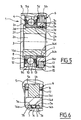
- the freewheel device As can be seen on the Figures 1 to 4 , the freewheel device, referenced 1 as a whole; comprises a tubular sleeve 2 of axis 3, a rolling bearing 4 mounted on the sleeve 2, an outer member 5 mounted on the bearing 4, a free wheel 6 mounted on the sleeve 2 and a friction element 7 mounted between the outer member 5 and freewheel 6.
- the sleeve 2 comprises a bore 2a, a front radial surface 2b, a cylindrical outer surface 2c extending over most of its length from the radial end surface 2b, a radial surface 2d extending towards the outside from the end of the cylindrical outer surface 2c, an axial surface 2e of short length extending from the free end of the radial portion 2d, axially opposite the radial end surface 2b , and a radial end surface 2f opposite to the radial end surface 2b.
- the bearing 4 may be of standard type, low cost of manufacture and comprises a solid inner ring 8 provided with a bore mounted, for example by fitting, on the outer cylindrical surface 2c of the sleeve 2, and in contact with the radial portion 2d, a massive outer ring 9, a row of elements 10, here balls, arranged between a raceway of the inner ring 8 and a raceway of the outer ring 9, a cage 11 for maintaining the circumferential spacing of the rolling elements 10 and seals 12 and 13 integral with the outer ring 9 and rubbing on a cylindrical surface of the inner ring 8, arranged on one side and the other of the row of rolling elements 10 to prevent the intrusion of foreign elements near the rolling elements 10 and to keep a lubricating product such as grease inside the bearing and near the rolling elements 10.
- the outer ring 9 is provided with an outer cylindrical surface 9a, coaxial with the outer cylindrical surface 2c of the sleeve 2.
- the outer element 5 comprises a central bore 5a mounted, for example by fitting, on the outer cylindrical surface 9a of the outer ring 9.
- the rolling bearing 4 thus ensures the freedom of rotation of the outer member 5 relative to the sleeve 2, and the resumption of radial efforts.
- the outer element 5 further comprises a bore 5b, of diameter very slightly greater than the central bore 5a, and disposed at the axial end of the outer element 5 located opposite the support 4.
- the bearing 4 and the outer element 5 are asymmetrical with respect to a radial plane passing through the center of the rolling elements 10.
- An annular radial surface 5c is formed between the bores 5a and 5b.
- the freewheel 6, mounted adjacent to the rolling bearing 4, comprises an outer ring 14, for example of solid type, whose bore forms a sliding track 14c, a row of wedging elements 15, here cams, a cage 16 provided with windows in which are arranged the wedging elements 15 in the form of cams and a spring 17 of return of the wedging elements 15 maintaining said wedging elements in permanent contact with the tracks.
- the wedging elements 15 are arranged radially between the outer cylindrical surface 2c of the sleeve 2 and the track 14c of the outer ring 14 axially between the rolling bearing 4 and the radial end surface 2b of the sleeve 2,
- the outer ring 14 comprises two circular ribs 14a, 14b, directed radially outward.
- the ribs 14a and 14b are disposed axially at the ends of the outer ring 14 while being aligned with the radial end surfaces of the outer ring 14 and surround an outer axial surface 14d of the outer ring 14.
- the friction element 7 is disposed between the ribs 14a and 14b and is thus axially integral with the outer ring 14.
- the friction element 7 is in the form of an open ring on a small angular sector, for example of the order of a few degrees.
- the friction element 7 has, in axial cross-section, a U-shape provided with two axial wings and may be made of rolled sheet.
- the friction element 7, in axial section comprises an axial portion 7a of small diameter, a radial portion 7b extending outwardly from one end of the axial portion 7a, a axial portion 7c extending opposite the axial section 7a from the large diameter end of the radial portion 7b, a radial portion 7d extending inwardly from the free end of the axial portion 7c and an axial portion 7e extending opposite the axial portion 7a from the small diameter end of the radial portion 7b.
- the axial portions 7a and 7e have a substantially identical diameter and are in contact with the outer surface of the solid ring 14, the free end of the axial portion 7a being disposed near the rib 14a and the free end of the portion axial 7e being disposed near the rib 14b.
- the friction element 7 is symmetrical with respect to a radial plane passing through the middle of the axial portion 7c.
- the axial portion 7c is in contact with the bore 9b of the outer member 5.
- the friction element 7 may be provided with a local or general coating to improve its friction or anti-corrosion properties.
- the jamming cams 15 bearing on the cylindrical outer surface 2c of the sleeve 2 and on the track 14c of the solid ring 14.
- the sleeve 2 is subjected to a torque that can be high and tends to rotate it clockwise.
- the torque transmitted from the outer element 5 to the friction element 7, from the friction element 7 to the free wheel 6 and from the free wheel 6 to the sleeve 2 exceeds a predetermined threshold, the element friction 7 begins to slide, relative to the solid ring 14 and / or relative to the outer member 5, and thus provides a clipping torque transmitted to the outer member 5.
- the predetermined torque threshold can be chosen at mounting and depends on the characteristics of the friction element and the surfaces with which said friction element is in contact.
- the assembly formed by the freewheel 6 and the friction element 7 torque limiter can be seen as a Zener diode which freely allows the passage of electrical current in one direction and prohibited in the other until a certain voltage is reached, voltage beyond which the current can again pass freely.
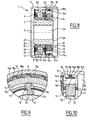
- the embodiment illustrated on the Figures 5 and 6 is similar to the above, except that the relative provisions of the free wheel 6 and the friction element 7 have been reversed, the friction element 7 is disposed between the cylindrical outer surface 2c of the sleeve 2 and the massive ring
- the wedging elements 15 are arranged between the track 14c formed on the outer cylindrical surface of the solid ring 14 and the bore 5b of the outer member 5.
- the operation is similar, with the exception of that the free wheel 6, in the jamming position, is integral with the outer element 5 and can move angularly relative to the sleeve 2 by sliding of the friction element 7.
- the embodiment illustrated on the figure 7 is to be compared with that illustrated on the Figures 1 to 4 , except that the friction element 7 is replaced by a circumferentially continuous friction element 18 fixed, for example by overmolding, on the outer ring 14 of the freewheel 6 between the ribs 14a and 14b and radially projecting towards the outside. 'outside.
- the friction element 18 is made of synthetic material. The choice of material and the radial prestressing of the friction element 18 between the solid ring 14 and the bore 5b of the outer element 5 determine the friction torque and therefore the maximum torque that can be transmitted between the outer element 5 and the outer element 5.
- Running tracks for the rolling elements 10 are formed directly on the sleeve 2 and on the outer member 5, respectively from the surfaces 2e and 5a.
- the axial surface 2e has an increased axial length with respect to the previous embodiments.
- the races are integral with the sleeve 2 and the outer member 5 respectively.
- the embodiment illustrated on the Figures 8 to 10 is similar to the one shown on the Figures 1 to 4 , except that the friction element 7 is replaced by a friction element 19 in the form of a sheet metal ring comprising radially resilient tongues 19a coming from the body 19b of the ring.
- the ring may be circumferentially continuous or present the shape of a band cut to good length and rolled on itself with its two ends end to end.
- the body 19b of the friction element 19 is disposed in contact with the solid ring 14 between the ribs 14a and 14b, while the tongues 19a, projecting radially outwardly, are in contact with the bore 9b of the element outside 5.
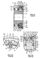
- the friction element 7 is replaced by an axially-acting friction device.
- the solid ring 14 of the freewheel 6 is of reduced radial thickness to leave a larger space for the torque limiting device 20 and is provided with an axial outer surface.
- a groove 21 is formed in the bore 5b of the outer member 5 to accommodate a circlip 22, near the free end of the bore 5b.
- the torque limiting device 20 which surrounds the solid ring 14 comprises two friction rings 23 comprising a friction portion 23a made of synthetic material and a support portion 23b, for example in the form of a flat metal washer.
- the friction portions 23a are secured to the support portion 23b for example by gluing or overmolding.
- the friction rings 23 are integral in rotation with the outer ring 14 of the freewheel 6 by means such as axial splines 24 cooperating with the bore of the support portions 23b of concordant shape.
- the friction rings 23 can move axially relative to the solid ring 14. Between the two friction rings 23 is disposed an axially acting washer 25, Belleville type washer or corrugated type.
- the torque limiting device 20 further comprises a cup-shaped ring 27 having an L-shaped section, fitted into the bore 5b of the outer element 5 and axially in abutting contact with the circlip 22 disposed in the groove 21.
- the ring 27 has a radial friction surface 27a.
- the friction portions 23a of the friction rings 23 have radial friction surfaces 23c, one in contact with the ring 27, and the other in contact with a radial surface 5c of the outer member 5 forming a shoulder between the bores 5a and 5b.
- the friction rings 23 are thus placed in elastic support against the corresponding friction surfaces of the outer element 5 and the ring 27 integral with the outer element 5.
- the choice of the material of the friction rings 23 and the prestressing axial of the rings by the washer 25 determines the friction torque and the maximum torque threshold transmittable. Of course, one could provide a variant comprising two washers 25 or a single ring 23 and a single washer 25.
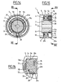
- the embodiment illustrated on the Figures 14 to 16 is close to the one shown on the Figures 1 to 4 , except that the freewheel 6 comprises a spring 28 provided with turns 29 in contact with the outer surface 2c of the sleeve 2 and one end 30 projecting outwards.
- the friction element 7 comprises a body 31 in the form of an open ring made of synthetic material and provided with an axial outer surface 31a in contact with the bore 5b of the outer element 5, a radial surface 31b connecting to the axial surface 31a, directed inward and in contact with the shoulder 5c of the outer member 5 and with a front radial surface of the outer ring 9 of the rolling bearing 4, an axial bore surface 31c fitted to the outer surface 2c of the sleeve 2 and a radial surface 31d disposed opposite the radial surface 31b and joining the inner axial 31c and outer 31a surfaces.
- the body 31 has a generally rectangular shape.
- an annular housing 32 disposed substantially at the center of the body 31 in the axial direction.
- a notch 33 occupying a small angular sector is formed between the housing 32 and the radial surface 31b in contact with the rolling bearing 4.
- the notch 33 opens on a radial front surface of the inner ring 8 of the rolling bearing 4.
- the turns 29 of the spring 28 are housed in the annular housing 32 while the outwardly projecting end 30 is housed in the notch 33.
- one of the free ends of the spring 28 is integral in rotation with the body 31 while the turns 29 are in frictional contact with the axial outer surface 2c of the sleeve 2.
- the spring tends to tighten and angularly secures said sleeve 2 and said body 31.
- the turns 29 tend to loosen.
- the sleeve 2 and the body 31 can freely rotate relative to each other in said relative direction of rotation with a slight friction of the turns 29 on the outer axial surface 2c of the sleeve 2.
- the body 31 further comprises another annular groove 34 formed from the radial surface 31d disposed opposite the rolling bearing 4 and having a slightly wider base radially than the inlet of said groove 34.
- a circlip 35 is disposed in the bottom of the groove 34 being radially temporarily shrunk during assembly.
- the groove 34 is dimensioned such that when the circlip 35 is in place in the bottom of the groove 34, said circlip 35 exerts on the body 31 a radially outward force.
- the body 31 being radially deformable by the material used and because said body 31 is an open ring, the outer surface 31a of the body 31 is prestressed radially on the bore 5b of the outer member 5, which ensures the joining together the body 31 and the outer member 5 to a certain torque which can be determined by the dimensions of the outer member 5, the body 31 and the circlip 35 as well as by their constituent materials.
- the body 31 forms a single element forming part of both the free wheel 6 and the friction element 7.
- the annular housing 32 and the notch 33 cooperate with the spring 28, and the axial outer surface 31a is in contact with the bore 5b of the outer member 5 with the possibility of sliding angularly with respect to said bore 5b in case of excessively high torque.
- the illustrated embodiments relate to freewheels whose wedging elements are cams or a spring.
- the invention could also operate with a free wheel whose wedging element or elements are one or pawls cooperating with a toothed track.
- the invention increases the longevity of the freewheel and mechanical members mounted upstream or downstream by filtering the torque peaks made by the friction member.
- the ring of the freewheel also cooperates with the friction member, hence a particularly compact assembly easy to transport, handle and mount in a mechanical assembly, for example between a cylindrical housing and a shaft.
Landscapes
- Engineering & Computer Science (AREA)
- General Engineering & Computer Science (AREA)
- Mechanical Engineering (AREA)
- One-Way And Automatic Clutches, And Combinations Of Different Clutches (AREA)
- Rolling Contact Bearings (AREA)
- Mechanical Operated Clutches (AREA)
- Sheets, Magazines, And Separation Thereof (AREA)
Claims (19)
- Freilauflageranordnung (1), zu der gehören: ein äußeres Element (5), ein in dem äußeren Element angeordnetes inneres Element und eine Freilaufeinrichtung (6), die wenigstens einen zwischen dem inneren Element und dem äußeren Element angeordnetes Klemmkörper (15) aufweist, das dazu dient, eine in einer Richtung eine Drehbewegung zwischen dem äußeren Element und dem inneren Element zuzulassen und in der anderen Richtung ein Drehmoment zwischen dem äußeren Element und dem inneren Element zu übertragen, wobei die Freilaufeinrichtung (6) einen Ring (14), der mit einer zylindrischen Innenfläche und einer zylindrischen Außenfläche (14d) versehen ist, die im Wesentlichen auf eine zu einer Rotationsachse der Anordnung rechtwinkeligen Radialebene ausgerichtet sind, und ein Drehmomentbegrenzungselement aufweist, das dazu eingerichtet ist, das durch die Freilaufeinrichtung übertragene Drehmoment zu begrenzen, wobei das Drehmomentbegrenzungselement in radialer Richtung zwischen dem Ring (14) und dem äußeren Element (5) oder dem inneren Element mit diesem Ring und dem jeweiligen Element in Berührung stehend angeordnet ist, dadurch gekennzeichnet, dass sie ein Wälzlager enthält, das es dem äußeren Element erlaubt sich relativ zu dem inneren Element zu drehen, wobei die Freilaufeinrichtung neben dem Wälzlager (4) angeordnet ist, das auf dem inneren Element (5) sitzt, und das äußere Element (5) auf dem Wälzlager gelagert ist.
- Anordnung nach Anspruch 1, dadurch gekennzeichnet, dass das Drehmomentbegrenzungselement mit der Freilaufeinrichtung (6) hintereinander liegend angeordnet ist, um das Drehmoment zu begrenzen, das durch das in nur eine Richtung wirkende Eingriffselement in der Drehmomentübertragungsstellung übertragen wird.
- Anordnung nach Anspruch 1 oder 2, dadurch gekennzeichnet, dass das Drehmomentbegrenzungselement wenigstens ein Reibelement (7) enthält.
- Anordnung nach Anspruch 3, dadurch gekennzeichnet, dass das Reibelement (20) eine radiale Reibfläche (23a) aufweist.
- Anordnung nach Anspruch 3, dadurch gekennzeichnet, dass das Reibelement (7) eine durch zwei Radialebenen begrenzte axiale Reibfläche aufweist.
- Anordnung nach Anspruch 1, dadurch gekennzeichnet, dass in dem inneren und äußeren Element Lagerlaufflächen für Wälzkörper des Lagers ausgebildet sind.
- Anordnung nach einem der vorhergehenden Ansprüche, dadurch gekennzeichnet, dass das Drehmomentbegrenzungselement auf einer Außenfläche (14d) der Freilaufeinrichtung angeordnet ist.
- Anordnung nach einem der Ansprüche 1 bis 8, dadurch gekennzeichnet, dass das Drehmomentbegrenzungselement in einem zylindrischen Innenraum der Freilaufeinrichtung angeordnet ist.
- Anordnung nach einem der vorhergehenden Ansprüche, dadurch gekennzeichnet, dass das Drehmomentbegrenzungselement einen offenen elastischen Ring enthält, der mit einer äußeren Reibfläche und einer inneren Reibfläche versehen ist.
- Anordnung nach Anspruch 11, dadurch gekennzeichnet, dass der Ring aus Stahlblech hergestellt ist und einen U-förmigen Querschnitt aufweist, der mit zwei axialen Flügeln versehen ist.
- Anordnung nach einem der vorhergehenden Ansprüche, dadurch gekennzeichnet, dass das Drehmomentbegrenzungselement eine Reihe von elastischen Zungen (19a) aufweist.
- Anordnung nach einem der vorhergehenden Ansprüche, dadurch gekennzeichnet, dass das Drehmomentbegrenzungselement einen aus Kunststoff hergestellten elastischen Ring (18) enthält, der mit einer äußeren oder inneren Reibfläche und einer inneren bzw. äußeren Befestigungsfläche ausgebildet ist.
- Anordnung nach einem der vorhergehenden Ansprüche, dadurch gekennzeichnet, dass das Drehmomentbegrenzungselement wenigstens einen Reibring (23) und eine Federscheibe (25) enthält, um den Reibring auf einer Reibfläche in axiale Anlage zu bringen.
- Anordnung nach einem der Ansprüche 1 bis 9, dadurch gekennzeichnet, dass das Drehmomentbegrenzungselement einen Grundkörper in Form eines offenen Ringes enthält.
- Anordnung nach Anspruch 14, dadurch gekennzeichnet, dass das Drehmomentbegrenzungselement außerdem ein elastisches Element enthält, das dazu dient, den Grundkörper vorzuspannen.
- Anordnung nach einem der vorhergehenden Ansprüche, dadurch gekennzeichnet, dass die Freilaufeinrichtung eine Feder enthält, die ein mit dem Drehmomentbegrenzungselement fest verbundenes Ende und Windungen aufweist, die mit dem inneren oder äußeren Element gleitend in Berührung stehen.
- Anordnung nach einem der vorhergehenden Ansprüche, dadurch gekennzeichnet, dass die Klemmkörper der Freilaufeinrichtung Nocken, Rollen oder Sperrklinken sind.
- Anordnung nach einem der vorhergehenden Ansprüche, dadurch gekennzeichnet, dass das Drehmomentbegrenzungselement ein Reibelement und ein Element enthält, das dazu dient, das Reibelement gegen den Ring (14) und/oder das äußere Element (5) oder gegen das innere Element vorzuspannen.
- Anordnung nach einem der vorhergehenden Ansprüche, dadurch gekennzeichnet, dass das Drehmomentbegrenzungselement zwischen zwei distinkten Elementen vorgespannt ist.
Applications Claiming Priority (2)
| Application Number | Priority Date | Filing Date | Title |
|---|---|---|---|
| FR0309239A FR2858376B1 (fr) | 2003-07-28 | 2003-07-28 | Dispositif de palier a roue libre avec limitateur de couple. |
| PCT/FR2004/001609 WO2005021991A1 (fr) | 2003-07-28 | 2004-06-25 | Dispositif de palier a roue libre avec limiteur de couple |
Publications (2)
| Publication Number | Publication Date |
|---|---|
| EP1651878A1 EP1651878A1 (de) | 2006-05-03 |
| EP1651878B1 true EP1651878B1 (de) | 2008-08-27 |
Family
ID=34043593
Family Applications (1)
| Application Number | Title | Priority Date | Filing Date |
|---|---|---|---|
| EP04767457A Expired - Lifetime EP1651878B1 (de) | 2003-07-28 | 2004-06-25 | Freilauflagervorrichtung mit drehmomentbegrenzer |
Country Status (6)
| Country | Link |
|---|---|
| US (2) | US7766140B2 (de) |
| EP (1) | EP1651878B1 (de) |
| AT (1) | ATE406526T1 (de) |
| DE (1) | DE602004016171D1 (de) |
| FR (1) | FR2858376B1 (de) |
| WO (1) | WO2005021991A1 (de) |
Families Citing this family (20)
| Publication number | Priority date | Publication date | Assignee | Title |
|---|---|---|---|---|
| FR2858376B1 (fr) * | 2003-07-28 | 2006-03-03 | Skf France | Dispositif de palier a roue libre avec limitateur de couple. |
| FR2902699B1 (fr) | 2006-06-26 | 2010-10-22 | Skf Ab | Dispositif de butee de suspension et jambe de force. |
| FR2906587B1 (fr) | 2006-10-03 | 2009-07-10 | Skf Ab | Dispositif de galet tendeur. |
| FR2913081B1 (fr) | 2007-02-27 | 2009-05-15 | Skf Ab | Dispositif de poulie debrayable |
| FR2914381B1 (fr) * | 2007-03-26 | 2009-07-03 | Skf Ab | Dispositif de poulie debrayable. |
| FR2932859B1 (fr) * | 2008-06-19 | 2010-12-10 | Skf Ab | Dispositif de transmission de couple notamment pour compresseur de climatisation |
| ITPD20080253A1 (it) * | 2008-08-20 | 2010-02-21 | Clerprem Spa | Bracciolo regolabile in inclinazione, in particolare per autoveicoli |
| CA2737064A1 (en) * | 2008-09-15 | 2010-03-18 | Magna Powertrain Inc. | Sealed one way roller clutch |
| WO2010051785A1 (de) * | 2008-11-10 | 2010-05-14 | Luk Lamellen Und Kupplungsbau Beteiligungs Kg Attn. Overdiek, Gerhard | Klemmkörperfreilauf |
| DE102009009528A1 (de) * | 2009-02-18 | 2010-08-19 | Schaeffler Technologies Gmbh & Co. Kg | Riemenscheibe mit Freilaufkupplung |
| US8376900B2 (en) | 2009-12-17 | 2013-02-19 | GM Global Technology Operations LLC | Clutch assembly |
| US8908027B2 (en) * | 2010-08-20 | 2014-12-09 | SeeScan, Inc. | Asymmetric drag force bearings for use with push-cable storage drums |
| DE102011081661B4 (de) * | 2011-08-26 | 2023-11-30 | Robert Bosch Gmbh | Schaltbares Getriebe für eine Handwerkzeugmaschine |
| FR3014038B1 (fr) * | 2013-11-29 | 2017-03-10 | Ifp Energies Now | Dispositif d'assemblage d'un accouplement automatique unidirectionnel avec des elements qui le porte et groupe motopropulseur utilisant un tel dispositif. |
| EP3456993B1 (de) * | 2017-09-14 | 2020-06-24 | Goodrich Actuation Systems Limited | Drehmomentübertragungsvorrichtung |
| JP2019078308A (ja) * | 2017-10-23 | 2019-05-23 | Nskワーナー株式会社 | 一方向クラッチ |
| CN107943288B (zh) * | 2017-11-16 | 2020-10-16 | 陈昭胜 | 智能穿戴装置、智能穿戴设备及控制方法 |
| JP6886661B2 (ja) * | 2017-12-26 | 2021-06-16 | 株式会社クボタ | 作業機 |
| DE102020107597B4 (de) * | 2020-03-19 | 2024-03-21 | Nidec Corporation | Aktuator eines Kraftfahrzeugautomatikgetriebes |
| US11512744B2 (en) * | 2020-03-26 | 2022-11-29 | Nsk-Warner K.K. | Clutch apparatus |
Family Cites Families (117)
| Publication number | Priority date | Publication date | Assignee | Title |
|---|---|---|---|---|
| DE916370C (de) * | 1951-08-08 | 1954-08-09 | Star Kugelhalter Ges M B H Deu | UEberlastungskupplung |
| US3926286A (en) * | 1973-02-05 | 1975-12-16 | Reell Precision Mfg | Spring grip clutch |
| FR2304829A1 (fr) * | 1975-03-21 | 1976-10-15 | Ferodo Sa | Butee de debrayage |
| US4046238A (en) * | 1976-02-03 | 1977-09-06 | Mendoza Orozco Hector | Free-wheeling mechanism for bicycles |
| US4319220A (en) * | 1976-08-31 | 1982-03-09 | Dennis G. Pappas | Alarm system for monitoring pressurized vehicular tires |
| DE2658748A1 (de) | 1976-12-24 | 1978-06-29 | Kugelfischer G Schaefer & Co | Waelzlager, vorzugsweise axiallager, zur drehbaren lagerung der federauflage von fahrzeugraedern |
| JPS57161344A (en) * | 1981-03-27 | 1982-10-04 | Nippon Denso Co Ltd | Belt tension control device |
| JPS58145522A (ja) * | 1982-02-20 | 1983-08-30 | Honda Motor Co Ltd | 車両用動力伝達装置 |
| US4601374A (en) * | 1982-04-22 | 1986-07-22 | Federal-Mogul Corporation | Hydraulic clutch piston and seal |
| FR2544429B1 (fr) * | 1983-04-15 | 1985-08-02 | Valeo | Procede pour le montage d'une butee de debrayage, et butee de debrayage correspondante, notamment pour vehicule automobile |
| DE3445541A1 (de) * | 1984-01-04 | 1985-07-11 | Skandiafabriken AB, Mullsjö | Fluessigkeits-fuellstandsanzeiger |
| GB8407519D0 (en) | 1984-03-22 | 1984-05-02 | Cambridge Electronic Ind | Tachogenerators |
| FR2577291B1 (fr) | 1985-02-08 | 1989-10-13 | Valeo | Butee d'embrayage autocentreuse, notamment pour vehicule automobile, a assemblage compact simplifie |
| US5033013A (en) * | 1985-04-22 | 1991-07-16 | Yamasa Tokei Meter Co., Ltd. | Method and apparatus for measuring the amount of exercise |
| US4699530A (en) * | 1985-06-28 | 1987-10-13 | Oiless Industry Co., Ltd. | Thrust ball bearing unit |
| DE3534462A1 (de) | 1985-09-27 | 1987-04-02 | Bosch Gmbh Robert | Warneinrichtung zur erkennung von schaeden an sich bewegenden teilen |
| FR2602872B1 (fr) | 1986-08-05 | 1989-03-31 | Renault | Capteur de vitesse angulaire et son application a un capteur combine de couple et de vitesse angulaire pour colonne de direction de vehicule automobile |
| DE3765236D1 (de) * | 1986-12-22 | 1990-10-31 | Siemens Ag | Winkellagegeber mit fotoelektrisch abtastbarer geberscheibe und zweifach gelagerter geberwelle. |
| FR2609126B1 (fr) * | 1986-12-29 | 1989-10-27 | Valeo | Butee de debrayage, notamment pour vehicule automobile |
| FR2611009B1 (fr) * | 1987-02-17 | 1989-05-19 | Valeo | Butee de debrayage, notamment pour vehicule automobile |
| FR2611244B1 (fr) | 1987-02-20 | 1991-07-05 | Valeo | Butee de debrayage a piece elastique a action axiale, notamment pour vehicule automobile |
| JPS63246516A (ja) * | 1987-04-02 | 1988-10-13 | Nippon Seiko Kk | クラツチレリ−ズ軸受装置 |
| FR2615568B1 (fr) | 1987-05-21 | 1991-10-31 | Equip Electr Moteur | Lanceur de demarreur a roue libre comportant un limiteur de couple |
| US4815867A (en) * | 1987-09-23 | 1989-03-28 | Federal-Mogul Corporation | Side assembled clip for self-aligning bearing |
| DE3742030C2 (de) * | 1987-12-11 | 1997-06-19 | Skf Gmbh | Schwenklager für Spannvorrichtungen |
| DE8810259U1 (de) * | 1988-08-12 | 1988-11-17 | Messer Griesheim Gmbh, 6000 Frankfurt | Spülblock |
| FR2640706B1 (fr) * | 1988-12-20 | 1991-02-01 | Roulements Soc Nouvelle | Roulement a capteur d'informations |
| US5008647A (en) * | 1989-02-06 | 1991-04-16 | Orleander S.A. | Wireless bicycle wheel monitor system |
| FR2645929B1 (fr) | 1989-04-18 | 1991-06-07 | Roulements Soc Nouvelle | Dispositif de serrage d'un roulement de butee sur un support coulissant |
| JPH0623579B2 (ja) * | 1989-06-30 | 1994-03-30 | エヌエスケー・ワーナー株式会社 | ワンウエイクラッチ |
| US5018384A (en) * | 1989-07-21 | 1991-05-28 | Nippon Seiko Kabushiki Kaisha | Rotational speed detector |
| FR2655735B1 (fr) | 1989-12-07 | 1994-05-13 | Skf France | Dispositif de capteur de vitesse de rotation. |
| IT1240481B (it) * | 1990-07-04 | 1993-12-17 | Skf Ind Spa | Dispositivo atto a permettere la rilevazione della velocita' di rotazione tra due organi in rotazione relativa quali gli organi di sopporto di una ruota di un veicolo. |
| FR2675860B1 (fr) | 1991-04-24 | 1993-08-20 | Jaeger | Roulement comprenant un capteur de vitesse. |
| FR2678329B1 (fr) | 1991-06-28 | 1993-09-03 | Roulements Soc Nouvelle | Montage d'etancheite pour capteur d'informations adapte a un roulement etanche. |
| US5234089A (en) * | 1991-09-26 | 1993-08-10 | Ntn Corporation | Torque limiter |
| IT1256785B (it) * | 1992-01-28 | 1995-12-15 | Skf Ind Spa | Complesso di tenuta con un dispositivo sensore a bordo, per un cuscinetto di rotolamento. |
| FR2688560B1 (fr) | 1992-03-11 | 1998-03-20 | Skf France | Butee d'embrayage a commande hydraulique. |
| DE4228899A1 (de) | 1992-08-29 | 1994-03-03 | Thomson Brandt Gmbh | Verfahren und Vorrichtung zur Kommutierung |
| DE4300083A1 (de) * | 1993-01-06 | 1994-07-07 | Masch Und Werkzeugbau Gmbh | Überlastkupplung |
| FR2703450A1 (fr) | 1993-03-31 | 1994-10-07 | Aut Comp | Codeur numérique incrémental absolu, installation et machine comportant ce codeur. |
| DE9417045U1 (de) | 1994-10-22 | 1994-12-15 | INA Wälzlager Schaeffler KG, 91074 Herzogenaurach | Vorrichtung zur Dämpfung von Drehschwingungen in einem Antriebsstrang |
| DE9418459U1 (de) | 1994-11-18 | 1995-02-02 | FAG OEM und Handel AG, 97421 Schweinfurt | Wälzlager mit Drehzahlsensor |
| US6539336B1 (en) * | 1996-12-12 | 2003-03-25 | Phatrat Technologies, Inc. | Sport monitoring system for determining airtime, speed, power absorbed and other factors such as drop distance |
| DE19503469C1 (de) * | 1995-02-03 | 1996-05-30 | Freudenberg Carl Fa | Dichtungsanordnung |
| FR2730566B1 (fr) * | 1995-02-09 | 1997-06-13 | Skf France | Dispositif de codeur pour capteur de vitesse de rotation et roulement equipe d'un tel dispositif |
| FR2730534B1 (fr) * | 1995-02-09 | 1997-04-04 | Valeo | Butee de debrayage a commande hydraulique pour un embrayage a diaphragme de vehicule automobile |
| US5592401A (en) * | 1995-02-28 | 1997-01-07 | Virtual Technologies, Inc. | Accurate, rapid, reliable position sensing using multiple sensing technologies |
| JPH08292111A (ja) * | 1995-04-24 | 1996-11-05 | Mitsubishi Electric Corp | ベルト張力測定装置 |
| US5598913A (en) * | 1995-06-07 | 1997-02-04 | Ntn Corporation | One-way over-running clutch pulley |
| JP3272910B2 (ja) * | 1995-06-16 | 2002-04-08 | シャープ株式会社 | スプリングクラッチ機構および給紙装置のクラッチ機構 |
| JPH0972394A (ja) | 1995-09-05 | 1997-03-18 | Nippon Soken Inc | 補機トルク検出システム |
| US5721539A (en) * | 1995-10-10 | 1998-02-24 | Goetzl; Brent A. | Speedometer for in-line skates |
| US6011491A (en) * | 1995-10-10 | 2000-01-04 | Goetzl; Brent A. | Speedometer for in-line skates |
| US5845230A (en) * | 1996-01-30 | 1998-12-01 | Skf Condition Monitoring | Apparatus and method for the remote monitoring of machine condition |
| DE29602000U1 (de) | 1996-02-06 | 1996-03-21 | Skf Gmbh, 97421 Schweinfurt | Tragkörper |
| DE19614385A1 (de) * | 1996-03-04 | 1997-09-11 | Schaeffler Waelzlager Kg | Dichtung für einen Ringkolben einer hydraulischen Kupplungs-Ausrückvorrichtung |
| US5780731A (en) * | 1996-04-11 | 1998-07-14 | Denso Corporation | Method for judging the locked state of auxiliaries for automobiles |
| JPH1030693A (ja) | 1996-07-16 | 1998-02-03 | Nippon Soken Inc | ベルト劣化判定方法 |
| DE29615910U1 (de) | 1996-08-05 | 1997-12-04 | Lumpert, Jürg B., Zürich | Sportgerät mit Datenanzeige für den Benutzer |
| DE19637585C2 (de) | 1996-09-14 | 1999-07-01 | Bernd Voelkel | Geschwindigkeitsmesser für Rollschuhe |
| FR2754903B1 (fr) * | 1996-10-23 | 1998-12-04 | Skf France | Dispositif de codeur pour capteur de vitesse de rotation et roulement equipe d'un tel dispositif |
| US6415900B1 (en) * | 1996-12-23 | 2002-07-09 | Valeo | Hydraulic control receiver with closing plate |
| DE19716218C2 (de) * | 1997-04-18 | 2001-08-30 | Schaeffler Waelzlager Ohg | Kupplungsausrücklager |
| DE29708535U1 (de) | 1997-05-05 | 1997-08-28 | Zimmermann, Hartmut, Dr.rer.nat., 12589 Berlin | Vorrichtung zur Erfassung von Bewegungsparametern beim In-Line-Skating |
| DE19809074A1 (de) | 1997-06-30 | 1999-01-07 | Schaeffler Waelzlager Ohg | Federbeinlagerung |
| US6257605B1 (en) * | 1997-06-30 | 2001-07-10 | Ina Walzlager Schaeffler Ohg | Suspension strut bearing |
| FR2772444B1 (fr) | 1997-12-11 | 2000-06-16 | Valeo | Recepteur hydraulique pour commande d'embrayage, notamment pour vehicule automobile |
| FR2772920B1 (fr) * | 1997-12-18 | 2000-02-04 | Skf France | Montage de roue de patin en ligne avec dispositif de detection de la vitesse de rotation |
| ITTO980035A1 (it) | 1998-01-16 | 1999-07-16 | Skf Ind Spa | Cuscinetto di rotolamento con dispositivo di rilevamento della velocit a' di rotazione. |
| US6013007A (en) * | 1998-03-26 | 2000-01-11 | Liquid Spark, Llc | Athlete's GPS-based performance monitor |
| FR2779096B1 (fr) * | 1998-05-28 | 2000-12-15 | Skf France | Dispositif de butee de suspension |
| US6196552B1 (en) * | 1998-06-08 | 2001-03-06 | Automotive Products (Usa), Inc. | Seal assembly for annular hydraulic cylinder |
| US6378678B1 (en) * | 1998-06-30 | 2002-04-30 | Automotive Products Uk, Ltd | Twin mass flywheel assemblies |
| GB9813961D0 (en) * | 1998-06-30 | 1998-08-26 | Renold Plc | Method and apparatus for tensioning a chain of an internal combustion engine |
| IT1304673B1 (it) | 1998-10-06 | 2001-03-28 | Skf Ind Spa | Metodo per la realizzazione di una ruota fonica per un cuscinettovolvente, e prodotto relativo. |
| FR2791103B1 (fr) * | 1999-03-17 | 2001-04-13 | Skf France | Palier a roulement instrumente |
| JP2000314638A (ja) * | 1999-04-28 | 2000-11-14 | Asahi Optical Co Ltd | エンコーダ |
| US6160480A (en) * | 1999-09-24 | 2000-12-12 | Su-Yueh; Hsien Huang | Wireless inline-skate and skate board pulse watch with speed and heart rate monitoring |
| US6666784B1 (en) * | 1999-10-06 | 2003-12-23 | Ntn Corporation | Piston rod piston detector, autotensioner and belt tension adjuster |
| JP4039785B2 (ja) | 2000-04-04 | 2008-01-30 | Ntn株式会社 | ベルト張力調整装置 |
| DE19960699B4 (de) * | 1999-12-16 | 2010-09-30 | Schaeffler Technologies Gmbh & Co. Kg | Federbeinlagerung |
| US6422502B1 (en) * | 2000-02-24 | 2002-07-23 | Ntn Corporation | Winding unit |
| DE10011820B4 (de) | 2000-03-10 | 2012-01-12 | Schaeffler Technologies Gmbh & Co. Kg | Messeinrichtung für Wälzlager |
| FR2807802B1 (fr) | 2000-04-12 | 2002-07-26 | Skf France | Butee de debrayage et element d'attaque pour butee de debrayage |
| IT1320364B1 (it) * | 2000-05-25 | 2003-11-26 | A E Assemblaggi Elettromeccani | Dispositivo sensore di usura di una cinghia o catena di trasmissione,particolarmente per una trasmissione di comando dell'albero di |
| DE50011024D1 (de) * | 2000-06-16 | 2005-09-29 | Amo Automatisierung Mestechnik | Induktives Längenmesssystem |
| WO2001098678A1 (fr) * | 2000-06-19 | 2001-12-27 | Nsk Ltd. | Dispositif de direction assistee entraine par moteur |
| DE10042677A1 (de) | 2000-08-31 | 2002-03-14 | Schaeffler Waelzlager Ohg | Gehäuse für ein Federbeinlager |
| FR2813644B1 (fr) * | 2000-09-06 | 2003-01-24 | Skf France | Dispositif de palier a roulement instrumente, notamment pour volant de commande |
| KR20020084145A (ko) * | 2000-12-22 | 2002-11-04 | 발레오 | 자동차용 클러치의 스러스트 베어링 및 피스톤과 볼베어링의 조립 방법 |
| FR2818708B1 (fr) | 2000-12-22 | 2003-04-25 | Skf Ab | Bl0c porte-capteur et palier a roulement a capteur d'informations |
| FR2819864B1 (fr) | 2001-01-23 | 2003-04-25 | Skf Ab | Dispositif de butee de debrayage autocentreuse |
| FR2820476B1 (fr) * | 2001-02-02 | 2004-04-02 | Skf Ab | Dispositif de detection de la vitesse de rotation d'un element tournant |
| JP2002310200A (ja) * | 2001-04-12 | 2002-10-23 | Nsk Warner Kk | ワンウェイクラッチ組立体 |
| US6817457B2 (en) * | 2001-07-26 | 2004-11-16 | Ntn Corporation | Two-way roller clutch with torque limiting feature |
| DE10144032A1 (de) * | 2001-09-07 | 2003-04-03 | Paul Mueller Gmbh & Co Kg | Freilauf mit einem mit faserverstärktem Kunststoff umwickelten Freilaufaußenring |
| FR2829429B1 (fr) * | 2001-09-12 | 2003-12-12 | Skf Ab | Dispositif de butee de suspension |
| US6554113B2 (en) * | 2001-09-20 | 2003-04-29 | Borgwarner, Inc. | Torque limiting accessory drive assembly |
| DE10148388A1 (de) | 2001-09-29 | 2003-04-24 | Ina Schaeffler Kg | Abdichtung für ein Wälzlager |
| FR2832201B1 (fr) * | 2001-11-13 | 2004-03-19 | Skf Ab | Dispositif tendeur instrumente et procede de controle associe |
| FR2835297B1 (fr) * | 2002-01-29 | 2004-04-16 | Skf Ab | Support de fixation, palier a roulement et procede de montage associes |
| FR2841304B1 (fr) * | 2002-06-20 | 2007-01-05 | Skf Ab | Dispositif de tension pour mise en precontrainte d'une tige et procede de tension associe |
| FR2841990B1 (fr) * | 2002-07-02 | 2005-07-29 | Skf Ab | Dispositif de palier a roulement instrumente et moteur electrique ainsi equipe |
| JP3924213B2 (ja) * | 2002-07-11 | 2007-06-06 | 株式会社東海理化電機製作所 | ウエビング巻取装置及びクラッチ機構 |
| FR2842576B1 (fr) | 2002-07-17 | 2004-10-08 | Skf Ab | Dispositif de palier a roue libre et poulie a roue libre |
| FR2851624B1 (fr) * | 2003-02-26 | 2006-03-31 | Skf Ab | Palier a roulement instrumente |
| FR2853165B1 (fr) * | 2003-03-27 | 2005-12-02 | Skf Ab | Ensemble capteur, et boitier pour la realisation d'un tel ensemble. |
| FR2853065B1 (fr) * | 2003-03-27 | 2006-01-06 | Skf Ab | Instrument de mesure portatif, notamment pur la pratique sportive. |
| FR2856447B1 (fr) * | 2003-06-18 | 2005-09-09 | Skf Ab | Butee de debrayage et procede de montage |
| FR2856448B1 (fr) * | 2003-06-18 | 2006-09-01 | Skf Ab | Butee de debrayage |
| FR2856757B1 (fr) * | 2003-06-27 | 2006-10-20 | Skf Ab | Palier a roulement instrumente et codeur pour ensemble capteur d'informations |
| FR2858376B1 (fr) * | 2003-07-28 | 2006-03-03 | Skf France | Dispositif de palier a roue libre avec limitateur de couple. |
| FR2859412B1 (fr) * | 2003-09-04 | 2006-02-24 | Skf Ab | Dispositif de butee de suspension |
| FR2860847B1 (fr) * | 2003-10-14 | 2006-03-31 | Skf Ab | Dispositif de butee de debrayage |
| FR2872558B1 (fr) * | 2004-07-02 | 2006-09-29 | Skf Ab | Butee de debrayage et procede de fabrication |
| EP1787757B1 (de) * | 2005-11-18 | 2008-05-28 | Metabowerke GmbH | Elektromotorisch angetriebenes Schraub-oder Bohrwerkzeuggerät mit Planetengetriebe |
-
2003
- 2003-07-28 FR FR0309239A patent/FR2858376B1/fr not_active Expired - Fee Related
-
2004
- 2004-06-25 DE DE602004016171T patent/DE602004016171D1/de not_active Expired - Lifetime
- 2004-06-25 AT AT04767457T patent/ATE406526T1/de not_active IP Right Cessation
- 2004-06-25 WO PCT/FR2004/001609 patent/WO2005021991A1/fr active IP Right Grant
- 2004-06-25 US US10/566,669 patent/US7766140B2/en not_active Expired - Fee Related
- 2004-06-25 EP EP04767457A patent/EP1651878B1/de not_active Expired - Lifetime
-
2010
- 2010-05-12 US US12/778,902 patent/US8123013B2/en not_active Expired - Fee Related
Also Published As
| Publication number | Publication date |
|---|---|
| US20070074945A1 (en) | 2007-04-05 |
| ATE406526T1 (de) | 2008-09-15 |
| FR2858376A1 (fr) | 2005-02-04 |
| FR2858376B1 (fr) | 2006-03-03 |
| US20100219038A1 (en) | 2010-09-02 |
| WO2005021991A1 (fr) | 2005-03-10 |
| US7766140B2 (en) | 2010-08-03 |
| DE602004016171D1 (de) | 2008-10-09 |
| US8123013B2 (en) | 2012-02-28 |
| EP1651878A1 (de) | 2006-05-03 |
Similar Documents
| Publication | Publication Date | Title |
|---|---|---|
| EP1651878B1 (de) | Freilauflagervorrichtung mit drehmomentbegrenzer | |
| EP1452753B1 (de) | Mit sensor ausgestattetes wälzlager | |
| FR2913081A1 (fr) | Dispositif de poulie debrayable | |
| EP1908980B1 (de) | Vorrichtung mit ausrückbarer Riemenscheibe | |
| FR2914381A1 (fr) | Dispositif de poulie debrayable. | |
| FR3080422A1 (fr) | Dispositif de poulie pour galet tendeur ou enrouleur | |
| FR2858377A1 (fr) | Dispositif de roue libre | |
| FR2922605A1 (fr) | Module debrayable pour systeme de transmission d'un couple de demarrage a un moteur a combustion interne | |
| FR2932859A1 (fr) | Dispositif de transmission de couple notamment pour compresseur de climatisation | |
| FR2835580A1 (fr) | Palier a roulement, notamment pour moteur electrique | |
| FR3086027A1 (fr) | Dispositif de poulie pour galet tendeur ou enrouleur | |
| EP1264113B1 (de) | Wälzlager für kraftfahrzeug- lenksäulen | |
| EP1639267B1 (de) | Vorrichtung und freilaufgehäuse | |
| EP2148102B1 (de) | Axiallastunempfindliches Notlager | |
| FR2993330A1 (fr) | Systeme mecanique a embrayage unidirectionnel et alternateur comprenant un tel systeme | |
| EP1900958B1 (de) | Vorrichtung mit ausrückbarer Riemenscheibe | |
| FR2848624A1 (fr) | Palier a roulement freine compact | |
| FR2836191A1 (fr) | Palier a roulement instrumente | |
| FR3090060A1 (fr) | Dispositif de poulie | |
| FR2933460A1 (fr) | Dispositif de poulie debrayable | |
| EP1500838B1 (de) | Freilaufvorrichtung, Riemenscheibe und Generator mit einem Freilauf | |
| FR2939855A1 (fr) | Roue libre pour dispositif de poulie debrayable | |
| EP1521916A1 (de) | Vorrichtung für freilauflager und freilaufscheibe | |
| FR2989752A1 (fr) | Assemblage d'une bague interieure de roulement sur un moyeu de double volant amortisseur | |
| FR2938033A1 (fr) | Dispositif de poulie debrayable |
Legal Events
| Date | Code | Title | Description |
|---|---|---|---|
| PUAI | Public reference made under article 153(3) epc to a published international application that has entered the european phase |
Free format text: ORIGINAL CODE: 0009012 |
|
| 17P | Request for examination filed |
Effective date: 20060127 |
|
| AK | Designated contracting states |
Kind code of ref document: A1 Designated state(s): AT BE BG CH CY CZ DE DK EE ES FI FR GB GR HU IE IT LI LU MC NL PL PT RO SE SI SK TR |
|
| 17Q | First examination report despatched |
Effective date: 20060519 |
|
| DAX | Request for extension of the european patent (deleted) | ||
| 17Q | First examination report despatched |
Effective date: 20060519 |
|
| RIN1 | Information on inventor provided before grant (corrected) |
Inventor name: CAILLAULT, CLAUDE Inventor name: LESCORAIL, ROMUALD Inventor name: HAMADA, VIRGINIE Inventor name: PONSON, FREDERIC Inventor name: POULLE, THIERRY |
|
| RIN1 | Information on inventor provided before grant (corrected) |
Inventor name: PONSON, FREDERIC Inventor name: CAILLAULT, CLAUDE Inventor name: LESCORAIL, ROMUALD Inventor name: POULLE, THIERRY Inventor name: HAMADA, VIRGINIE |
|
| GRAP | Despatch of communication of intention to grant a patent |
Free format text: ORIGINAL CODE: EPIDOSNIGR1 |
|
| GRAS | Grant fee paid |
Free format text: ORIGINAL CODE: EPIDOSNIGR3 |
|
| GRAA | (expected) grant |
Free format text: ORIGINAL CODE: 0009210 |
|
| AK | Designated contracting states |
Kind code of ref document: B1 Designated state(s): AT BE BG CH CY CZ DE DK EE ES FI FR GB GR HU IE IT LI LU MC NL PL PT RO SE SI SK TR |
|
| REG | Reference to a national code |
Ref country code: GB Ref legal event code: FG4D Free format text: NOT ENGLISH |
|
| REG | Reference to a national code |
Ref country code: CH Ref legal event code: EP |
|
| REG | Reference to a national code |
Ref country code: IE Ref legal event code: FG4D Free format text: LANGUAGE OF EP DOCUMENT: FRENCH |
|
| REF | Corresponds to: |
Ref document number: 602004016171 Country of ref document: DE Date of ref document: 20081009 Kind code of ref document: P |
|
| PG25 | Lapsed in a contracting state [announced via postgrant information from national office to epo] |
Ref country code: ES Free format text: LAPSE BECAUSE OF FAILURE TO SUBMIT A TRANSLATION OF THE DESCRIPTION OR TO PAY THE FEE WITHIN THE PRESCRIBED TIME-LIMIT Effective date: 20081208 Ref country code: NL Free format text: LAPSE BECAUSE OF FAILURE TO SUBMIT A TRANSLATION OF THE DESCRIPTION OR TO PAY THE FEE WITHIN THE PRESCRIBED TIME-LIMIT Effective date: 20080827 |
|
| PG25 | Lapsed in a contracting state [announced via postgrant information from national office to epo] |
Ref country code: SI Free format text: LAPSE BECAUSE OF FAILURE TO SUBMIT A TRANSLATION OF THE DESCRIPTION OR TO PAY THE FEE WITHIN THE PRESCRIBED TIME-LIMIT Effective date: 20080827 Ref country code: AT Free format text: LAPSE BECAUSE OF FAILURE TO SUBMIT A TRANSLATION OF THE DESCRIPTION OR TO PAY THE FEE WITHIN THE PRESCRIBED TIME-LIMIT Effective date: 20080827 Ref country code: FI Free format text: LAPSE BECAUSE OF FAILURE TO SUBMIT A TRANSLATION OF THE DESCRIPTION OR TO PAY THE FEE WITHIN THE PRESCRIBED TIME-LIMIT Effective date: 20080827 |
|
| REG | Reference to a national code |
Ref country code: IE Ref legal event code: FD4D |
|
| PG25 | Lapsed in a contracting state [announced via postgrant information from national office to epo] |
Ref country code: IE Free format text: LAPSE BECAUSE OF FAILURE TO SUBMIT A TRANSLATION OF THE DESCRIPTION OR TO PAY THE FEE WITHIN THE PRESCRIBED TIME-LIMIT Effective date: 20080827 Ref country code: DK Free format text: LAPSE BECAUSE OF FAILURE TO SUBMIT A TRANSLATION OF THE DESCRIPTION OR TO PAY THE FEE WITHIN THE PRESCRIBED TIME-LIMIT Effective date: 20080827 Ref country code: BG Free format text: LAPSE BECAUSE OF FAILURE TO SUBMIT A TRANSLATION OF THE DESCRIPTION OR TO PAY THE FEE WITHIN THE PRESCRIBED TIME-LIMIT Effective date: 20081127 |
|
| PG25 | Lapsed in a contracting state [announced via postgrant information from national office to epo] |
Ref country code: CZ Free format text: LAPSE BECAUSE OF FAILURE TO SUBMIT A TRANSLATION OF THE DESCRIPTION OR TO PAY THE FEE WITHIN THE PRESCRIBED TIME-LIMIT Effective date: 20080827 Ref country code: RO Free format text: LAPSE BECAUSE OF FAILURE TO SUBMIT A TRANSLATION OF THE DESCRIPTION OR TO PAY THE FEE WITHIN THE PRESCRIBED TIME-LIMIT Effective date: 20080827 Ref country code: PT Free format text: LAPSE BECAUSE OF FAILURE TO SUBMIT A TRANSLATION OF THE DESCRIPTION OR TO PAY THE FEE WITHIN THE PRESCRIBED TIME-LIMIT Effective date: 20090127 Ref country code: SK Free format text: LAPSE BECAUSE OF FAILURE TO SUBMIT A TRANSLATION OF THE DESCRIPTION OR TO PAY THE FEE WITHIN THE PRESCRIBED TIME-LIMIT Effective date: 20080827 |
|
| PLBE | No opposition filed within time limit |
Free format text: ORIGINAL CODE: 0009261 |
|
| STAA | Information on the status of an ep patent application or granted ep patent |
Free format text: STATUS: NO OPPOSITION FILED WITHIN TIME LIMIT |
|
| PG25 | Lapsed in a contracting state [announced via postgrant information from national office to epo] |
Ref country code: EE Free format text: LAPSE BECAUSE OF FAILURE TO SUBMIT A TRANSLATION OF THE DESCRIPTION OR TO PAY THE FEE WITHIN THE PRESCRIBED TIME-LIMIT Effective date: 20080827 |
|
| 26N | No opposition filed |
Effective date: 20090528 |
|
| BERE | Be: lapsed |
Owner name: SKF FRANCE Effective date: 20090630 |
|
| PG25 | Lapsed in a contracting state [announced via postgrant information from national office to epo] |
Ref country code: SE Free format text: LAPSE BECAUSE OF FAILURE TO SUBMIT A TRANSLATION OF THE DESCRIPTION OR TO PAY THE FEE WITHIN THE PRESCRIBED TIME-LIMIT Effective date: 20081127 Ref country code: MC Free format text: LAPSE BECAUSE OF NON-PAYMENT OF DUE FEES Effective date: 20090630 |
|
| REG | Reference to a national code |
Ref country code: CH Ref legal event code: PL |
|
| PG25 | Lapsed in a contracting state [announced via postgrant information from national office to epo] |
Ref country code: CH Free format text: LAPSE BECAUSE OF NON-PAYMENT OF DUE FEES Effective date: 20090630 Ref country code: LI Free format text: LAPSE BECAUSE OF NON-PAYMENT OF DUE FEES Effective date: 20090630 |
|
| PG25 | Lapsed in a contracting state [announced via postgrant information from national office to epo] |
Ref country code: PL Free format text: LAPSE BECAUSE OF FAILURE TO SUBMIT A TRANSLATION OF THE DESCRIPTION OR TO PAY THE FEE WITHIN THE PRESCRIBED TIME-LIMIT Effective date: 20080827 |
|
| PG25 | Lapsed in a contracting state [announced via postgrant information from national office to epo] |
Ref country code: BE Free format text: LAPSE BECAUSE OF NON-PAYMENT OF DUE FEES Effective date: 20090630 |
|
| PG25 | Lapsed in a contracting state [announced via postgrant information from national office to epo] |
Ref country code: GR Free format text: LAPSE BECAUSE OF FAILURE TO SUBMIT A TRANSLATION OF THE DESCRIPTION OR TO PAY THE FEE WITHIN THE PRESCRIBED TIME-LIMIT Effective date: 20081128 |
|
| PG25 | Lapsed in a contracting state [announced via postgrant information from national office to epo] |
Ref country code: LU Free format text: LAPSE BECAUSE OF NON-PAYMENT OF DUE FEES Effective date: 20090625 |
|
| PG25 | Lapsed in a contracting state [announced via postgrant information from national office to epo] |
Ref country code: HU Free format text: LAPSE BECAUSE OF FAILURE TO SUBMIT A TRANSLATION OF THE DESCRIPTION OR TO PAY THE FEE WITHIN THE PRESCRIBED TIME-LIMIT Effective date: 20090228 |
|
| PG25 | Lapsed in a contracting state [announced via postgrant information from national office to epo] |
Ref country code: TR Free format text: LAPSE BECAUSE OF FAILURE TO SUBMIT A TRANSLATION OF THE DESCRIPTION OR TO PAY THE FEE WITHIN THE PRESCRIBED TIME-LIMIT Effective date: 20080827 |
|
| PG25 | Lapsed in a contracting state [announced via postgrant information from national office to epo] |
Ref country code: CY Free format text: LAPSE BECAUSE OF FAILURE TO SUBMIT A TRANSLATION OF THE DESCRIPTION OR TO PAY THE FEE WITHIN THE PRESCRIBED TIME-LIMIT Effective date: 20080827 |
|
| PGFP | Annual fee paid to national office [announced via postgrant information from national office to epo] |
Ref country code: GB Payment date: 20120629 Year of fee payment: 9 |
|
| PGFP | Annual fee paid to national office [announced via postgrant information from national office to epo] |
Ref country code: DE Payment date: 20120830 Year of fee payment: 9 Ref country code: IT Payment date: 20120628 Year of fee payment: 9 |
|
| GBPC | Gb: european patent ceased through non-payment of renewal fee |
Effective date: 20130625 |
|
| REG | Reference to a national code |
Ref country code: DE Ref legal event code: R119 Ref document number: 602004016171 Country of ref document: DE Effective date: 20140101 |
|
| PG25 | Lapsed in a contracting state [announced via postgrant information from national office to epo] |
Ref country code: DE Free format text: LAPSE BECAUSE OF NON-PAYMENT OF DUE FEES Effective date: 20140101 Ref country code: GB Free format text: LAPSE BECAUSE OF NON-PAYMENT OF DUE FEES Effective date: 20130625 |
|
| PG25 | Lapsed in a contracting state [announced via postgrant information from national office to epo] |
Ref country code: IT Free format text: LAPSE BECAUSE OF NON-PAYMENT OF DUE FEES Effective date: 20130625 |
|
| REG | Reference to a national code |
Ref country code: FR Ref legal event code: PLFP Year of fee payment: 12 |
|
| PGFP | Annual fee paid to national office [announced via postgrant information from national office to epo] |
Ref country code: FR Payment date: 20150630 Year of fee payment: 12 |
|
| REG | Reference to a national code |
Ref country code: FR Ref legal event code: ST Effective date: 20170228 |
|
| PG25 | Lapsed in a contracting state [announced via postgrant information from national office to epo] |
Ref country code: FR Free format text: LAPSE BECAUSE OF NON-PAYMENT OF DUE FEES Effective date: 20160630 |