EP1908980B1 - Vorrichtung mit ausrückbarer Riemenscheibe - Google Patents
Vorrichtung mit ausrückbarer Riemenscheibe Download PDFInfo
- Publication number
- EP1908980B1 EP1908980B1 EP07116412A EP07116412A EP1908980B1 EP 1908980 B1 EP1908980 B1 EP 1908980B1 EP 07116412 A EP07116412 A EP 07116412A EP 07116412 A EP07116412 A EP 07116412A EP 1908980 B1 EP1908980 B1 EP 1908980B1
- Authority
- EP
- European Patent Office
- Prior art keywords
- cage
- pulley
- friction
- freewheel
- inner transmission
- Prior art date
- Legal status (The legal status is an assumption and is not a legal conclusion. Google has not performed a legal analysis and makes no representation as to the accuracy of the status listed.)
- Not-in-force
Links
Images

Classifications
-
- F—MECHANICAL ENGINEERING; LIGHTING; HEATING; WEAPONS; BLASTING
- F16—ENGINEERING ELEMENTS AND UNITS; GENERAL MEASURES FOR PRODUCING AND MAINTAINING EFFECTIVE FUNCTIONING OF MACHINES OR INSTALLATIONS; THERMAL INSULATION IN GENERAL
- F16D—COUPLINGS FOR TRANSMITTING ROTATION; CLUTCHES; BRAKES
- F16D41/00—Freewheels or freewheel clutches
- F16D41/06—Freewheels or freewheel clutches with intermediate wedging coupling members between an inner and an outer surface
- F16D41/069—Freewheels or freewheel clutches with intermediate wedging coupling members between an inner and an outer surface the intermediate members wedging by pivoting or rocking, e.g. sprags
- F16D41/07—Freewheels or freewheel clutches with intermediate wedging coupling members between an inner and an outer surface the intermediate members wedging by pivoting or rocking, e.g. sprags between two cylindrical surfaces
Definitions
- the present invention relates to the field of freewheels.
- the present invention relates to the field of disengageable pulleys equipped with freewheels used for example in the drive pulleys of alternators in a motor vehicle.
- Such disengageable pulleys are known in themselves and are increasingly used to remedy the adverse effects of sudden motor acyclisms or decelerations that occur in internal combustion engines, particularly at low speeds and especially in diesel engines.
- a drive belt which is connected to the engine by means of a crankshaft pulley, can suddenly decelerate while a driven pulley, for example a pulley of the alternator, tends, by inertia, to keep turning at the same speed.
- Such variations generate adverse effects such as abnormal belt fatigue with risk of rupture, a sliding thereof on the pulley, or a vibration of the belt strands between the pulleys.
- a freewheel has been incorporated between the driven pulley and the driven shaft which makes it possible to temporarily disconnect the pulley from the shaft in the event of sudden deceleration of said pulley.
- Such a disengageable pulley is known in particular by the document JP 2005-282856 and generally comprises two bearings disposed on each side of the pulley, and a free wheel mounted between the two bearings and provided with a plurality of jamming cams and a cage having a plurality of windows for housing said cams.
- this document provides for fixing the holding cage on the driven shaft in order to drive the cage and the shaft at the same angular speed. In this way, when the pulley is in the disengaged position in which it operates freewheeling, there is a slip only between the cams and a sliding path located inside the pulley which is properly lubricated by the centrifugal force. which tends to project the lubricant to the outside.
- the cage has no degree of angular freedom with respect to the driven shaft.
- the Applicant has found that this can adversely affect the operational safety of the freewheel notably by causing risks of interference between the cams and the edges of the windows of the holding cage when the cams tilt.
- Such a device has the disadvantage of using two holding cages, one of which is provided with friction elements which are made in the form of clips, which increases the cost price of the device.
- the device may be lacking, for certain applications, responsiveness to quickly move from a freewheel operation to an operation in couple. This is particularly the case for an application on an alternator in which the acyclisms result in extremely rapid variations in the rotational speed of the engine.
- the present invention therefore aims to overcome the aforementioned drawbacks.
- the present invention is intended in particular to provide a disengageable pulley in which it would be possible to move more quickly from a freewheel position to a position in torque, and vice versa.
- the present invention also aims to provide a disengageable pulley which comprises economic components to manufacture and assemble.
- the present invention aims to provide a disengageable pulley with good reliability.
- the disengagable pulley device comprises a pulley mounted on an inner transmission member, and a freewheel provided with a plurality of wedging elements, such as cams, mounted between a sliding path of the pulley and a sliding path. of the inner transmission element. Said free wheel is intended to ensure a unidirectional clutch between the pulley and the inner transmission element.
- the device is provided with a cage for the wedging elements, at least one annular friction element provided between the cage and the sliding path of the inner transmission element for frictionally connecting the cage and the inner element. transmission, and at least one elastic return element disposed between at least one wedging element and the cage, the elastic return element tending to keep the wedging elements in contact with the sliding paths during a position engaged and in a disengaged position of the freewheel.
- the elastic return element is disposed between the wedging element and the cage which is driven by the inner transmission element, thanks to the friction element.
- the Applicant has determined that the relative provision of the elastic return element and the cage allows in particular to tend to maintain a permanent contact between the sliding paths of the device in the engaged position and in the disengaged position.
- the annular friction element provided between the cage and the sliding path of the inner transmission element tends to cause the freewheeling through said cage at the same speed as the inner transmission element as long as a drag torque due to friction of the wedging elements on the slip path of the pulley is less than the frictional torque between the friction element and the part on which it is intended to rub, ie the cage or the inner transmission element.
- the frictional coupling between the cage and the inner transmission element may also allow the cage to rotate slightly with respect to the inner element, for example in the case where the wedging elements would force against the edges of the housing. alveoli or windows when tilting. Indeed, under these conditions, the wedging elements tend to rotate the cage which can move angularly relative to the inner transmission element. This prevents jamming of the wedging elements by the cage, or deterioration of said cage. This further promotes a good operation of the freewheel.
- the annular friction element is distinct from the elastic return element associated with at least one of the wedging elements.
- a friction element makes it possible to provide, on the part intended to be driven, a surface of substantially flat contact and without projecting elements forming meshing teeth requiring adjustment during assembly.
- the pulley comprises a single cage for the wedging elements.
- the cage is monobloc.
- the freewheel is devoid of an additional cage of different radius to that of the cage and capable of tilting the cams of the engaged position.
- the friction element is circumferentially continuous.
- the inner transmission element tends to drive the free wheel substantially at the same speed, through the friction element and the cage.
- the annular friction element is mounted on the cage.
- At least one elastic return element is disposed between each wedging element and the cage.
- the elastic return element is disposed radially between the cage and the inner transmission element.
- the freewheel includes engaging cams.
- the slip path of the inner transmission member for the wedging members is formed directly by an outer surface of said inner transmission member.
- the sliding path of the pulley for the wedging elements is formed directly by a bore of said pulley.
- the annular friction element may comprise an elastic zone radially towards an outer surface of the inner transmission element.
- the annular friction element is disposed on a radial portion of the cage.
- the annular friction element is disposed on an axial portion of the cage.
- the annular friction element comprises a friction body and a clamping ring of the body in frictional contact.
- the annular friction element may comprise a friction lip supported by a radially elastic zone.
- the friction element consists of a friction body.
- the friction element can be attached to the cage.
- the friction element is distinct from the cage. It is also possible to provide the friction element and the one-piece cage.
- the device comprises at least two bearings, the freewheel being arranged axially between the bearings.
- the disengagable pulley device may be mounted on an alternator shaft for driving said alternator.
- the pulley can be mounted on a central shaft, in particular by means of a freewheel.
- the drive shaft can be mounted on the alternator shaft.
- a drive belt driven by the motor may come to bear on a periphery of the pulley.
- the pulley drives the central shaft when the motor accelerates or is in a substantially continuous mode or decelerates very slowly.
- the central axis of the disengagable pulley device can continue to rotate faster than the actual pulley thanks to the freewheel, thus sparing excessive stresses on the drive belt.
- the invention tends to keep the wedging elements in constant contact with the sliding paths during an engaged position and in a disengaged position of the freewheel, which allows in particular to pass almost instantaneously from a freewheel position to a torque-engaged position, and vice versa.
- the invention also makes it possible and to limit the wear of the wedging elements which slide mainly on the outer track of the pulley which is perfectly lubricated during the rotation of the device.
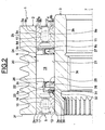
- the disengageable pulley device 1 comprises a pulley 2, an inner transmission element 3, for example a hollow shaft, two rolling bearings 4 and 5, and a free wheel 6.
- the pulley 2, of axis 7, has an outer surface provided with a grooved zone 2a with annular grooves and an axial zone 2b formed at an axial end of the grooved zone 2a.
- the pulley 2 comprises a cylindrical bore 2c extending over the entire length of the pulley 2, with the exception of chamfers 2d and 2e each disposed at one axial end, and two radial front surfaces 2f and 2g.
- the inner transmission element 3 which is in the form of a hollow shaft, has a cylindrical axial outer surface 3a on which is provided at each of the axial ends, a chamfer (not referenced).
- the inner transmission element 3 also has a bore 3b, a portion 3c has a thread for attachment to the end of an alternator shaft and the drive of said shaft (not shown).
- the bearing 4 coaxial with the axis 7, comprises an inner ring 8, an outer ring 9, between which are housed a row of rolling elements 10 made here in the form of balls, a cage 11 for maintaining the circumferential space rolling elements 10, and a seal 12.
- the inner ring 8 comprises a bore 8a of cylindrical shape, fitted with the outer surface 3a of the inner transmission element 3, and delimited by two radial side surfaces 8b and 8c opposite, and an outer cylindrical surface 8d staged from which is formed a circular groove 8e having in cross section a concave internal profile adapted to form a raceway for the rolling elements 10, said groove being oriented outwardly.
- the outer ring 9 comprises an outer cylindrical surface 9a fitted into the bore 2c of the pulley 2 and delimited by front surfaces 9b and 9c, and a stepped bore 9d of cylindrical shape from which is formed a circular groove 9e having in cross section a concave internal profile adapted to form a raceway for the rolling elements 10 facing inwards .
- the bore 9d here comprises two annular grooves (not referenced) symmetrical to each other with respect to a plane passing through the center of the rolling elements 10. Inside the annular groove located on the outside of the bearing 4 is mounted the seal sealing 12 which rubs against the cylindrical outer surface 8d of the inner ring 8 to form a seal.
- the seal 12 is arranged radially between the inner and outer rings 8, 9, and mounted axially between the rolling elements 10 and the radial surfaces 8b and 9b of the rings 8 and 9. Said surfaces are flush with the axial radial front surface 2g pulley 2.
- the bearing 5, coaxial with the axis 7, comprises an inner ring 13 fitted with the outer surface 3a of the inner transmission element 3, an outer ring 14 fitted into the bore 2c of the pulley 2, between which are housed a row of rolling elements 15 made here in the form of balls, a cage 16 for maintaining the circumferential space of the rolling elements 15, and a metal seal 17.
- the bearing 5 is identical to the bearing 4, and is arranged symmetrically with respect to it by considering a radial plane passing through the center of the pulley 2. The bearing 5 is thus flush with the axial radial front surface 2f of the pulley. 2.
- the bearings 4 and 5 are therefore arranged at each axial end of the pulley 2, the free wheel 6 being mounted axially between them. Freewheel 6 thus benefits from protection against intrusion foreign elements through the bearings 4 and 5, including seals 12 and 17.
- the free wheel 6 comprises a plurality of wedging elements or cams 19 arranged between two sliding paths 20 and 21, cylindrical in shape of revolution.
- the cams 19 are of the "engaging" type, that is to say having a tendency, under the effect of centrifugal forces during the rotation of the freewheel, to swing in the direction favoring their locking between the two sliding paths. 20 and 21, in order to facilitate an almost instantaneous transition from freewheel operation to torque-driven operation.
- the sliding path 20 is formed by the bore 2c of the pulley 2.
- the sliding path 21 is formed by the axial outer surface 3a of the shaft 3.
- the pulley 2 can be manufactured with an inner surface of particularly simple form entirely axial except for the chamfers 2d and 2e end.
- the pulley 2 can be obtained at low cost.
- This inner surface constitutes an outer surface for the cams 19, or of large diameter.
- the sliding path 21 is formed on the outer surface 3a of the shaft 3.
- the outer profile of revolution of the shaft 3 has the same diameter along its entire length. The finishing can be carried out in a single operation on a grinding machine and makes it possible to obtain, in large numbers and at low cost, the sliding path 21 of small diameter, or internal bearing, for the cams 19 of the freewheel 6.
- the free wheel 6 also comprises a cage 22 of generally annular shape that can be made of a metallic material, especially in steel, or from a synthetic material such as polyamide.
- the cage 22 comprises an axial portion 23 and two radial portions 24, 25.
- the radial portion 24 extends radially outwardly an axial end of the portion 23 located in the vicinity of the bearing 4, while the radial portion 25 extends radially towards the outside. an axial end of the portion 23 located in the vicinity of the bearing 5.
- the free ends of the radial portions 24 and 25 are located near the bore 2c of the pulley 2 and the outer surface 3a of the inner member of transmission 3, respectively. In other words, the radial portion 24 remains at a distance from the bore 2c, the radial portion 25 remaining remote from the outer surface 3a.
- the cage 22 also comprises a plurality of windows 26 formed in the axial portion 23 and forming a housing for the cams 19.
- the windows 26 are regularly spaced relative to each other in the circumferential direction.
- the cage 22 allows a circumferential maintenance of the cams 19 at regular spacing.
- the free wheel 6 further comprises a spring 27 which is in the form of an annular metal strip wound on itself and connected end-to-end or with partial overlap.
- the spring 27 is mounted inside the cage 22, and more particularly disposed radially between the outer surface 3a of the transmission element 3 and the axial portion 23 of the cage 22.
- the spring 27 is located axially between the portions radial 24 and 25 of the cage 22.
- the spring 27 also comprises cells or windows 28 which correspond to those of the cage 22 to be able to mount the Thus, the windows 28 are circumferentially evenly spaced.
- the spring 27 is further provided with at least one resilient return element 29 per cam 19 formed in the form of a tongue, and provided to press a surface provided for this purpose on the associated cam 19 to exert a torque tilting action tending to keep the cams 19 in contact with the sliding paths 20 and 21. In a static position, the return elements 29 exert a force directed towards the pulley 2.
- an individual return element associated with each cam exerts a force tending to maintain permanent contact with the sliding paths 20 and 21.
- each of the cams 19 it is possible for each of the cams 19 to mount an elastic return spring disposed between the cam 19 and the cage 22.
- the freewheel 6 also comprises an annular friction element 30 provided between the cage 22 and the outer surface 3a of the inner element 3.
- the friction element 30 is here attached to the cage 22.
- a friction element 30 is mounted on the outer surface 3a of the inner transmission element 3.
- the annular friction member comprises a friction body 31 and a resilient clamping ring 32 of the body surrounding a portion of the body in frictional contact with the inner transmission member 3.
- the annular friction body 31 is made of synthetic material, for example elastomer. I1 is provided with a radial portion (not referenced) fixed to the free end of the radial portion 25 of the cage 22, a first oblique portion (not referenced) extending inwardly the radial portion in the direction of the 'element 3 and cams 19, and a second oblique portion (not referenced) extending outwardly a small diameter edge of the first oblique portion. An inner surface of the junction zone of the first and second oblique portions comes into frictional contact against the outer surface 3a of the transmission element 3.
- the friction body 31 may advantageously be overmoulded directly on the radial portion 25 of the cage 22 so as to obtain a unitary assembly, and has a high coefficient of friction so as to be able to rotate the transmission element 3.
- the elastic clamping ring 32 is made of metal material. I1 is mounted in abutment against an outer surface of said junction zone of the first and second oblique portions. It forms a spring and is able to prestress radially the friction body 31 on the outer surface 3a of the inner transmission element 3 in order to keep these two elements in contact and to catch up with the wear.
- the operating mode of the freewheel 6 is as follows. During a steady state or during an acceleration of the pulley 2, the cams 19 tend, under the effect of the centrifugal forces and by contact with the sliding paths 20 and 21, to tilt in a first direction which allows to obtain by jamming between the two sliding paths a blocking with the two sliding paths 20 and 21 of the pulley 2 and the inner element 3 transmission.
- the freewheel 6 operates in torque or engaged engagement and transmits a drive torque between the pulley 2 and the inner member 3.
- the annular friction element provided between the cage 22 and the sliding path 21 of the inner transmission element 3 tends to drive the freewheel 6 by friction through said cage. the same speed as the inner element 3 transmission.
- the inner transmission element 3 and the cage 22 are integral in rotation and thus eliminates or limits the relative sliding between the sliding path 21 provided on the inner transmission element 3 and the cams 19. the inner transmission element 3 are in contact but with little or no relative slip.
- This rotational drive is effective as long as a drag torque due to the friction of the cams 19 on the sliding path 20 of the pulley 2 is less than the frictional torque between the friction element 30 and the outer surface 3a of the internal transmission element 3. In this case, there is then a slip with contact between the cams 19 and the sliding path 21.
- the elastic clamping ring 32 makes it possible to deform radially inwards the zone of joining the oblique portions to maintain frictional contact between the element 30 and the inner transmission element 3. In other words, the clamping ring 32 makes it possible to obtain a wear-compensating friction element.
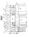
- the embodiment illustrated on the figure 3 differs in that the freewheel 6 is provided with an annular friction element 35 comprising a body 36 provided with a radially elastic zone and a lip 37 in frictional contact with the inner transmission element 3.
- the friction element 35 in one piece, is made of synthetic material, for example polyamide or elastomer.
- the radially elastic zone here comprises a first annular (unreferenced) axial portion fixed on the radial portion 25 of the cage 22, which is extended inwards by a first oblique portion extending inward towards the spring 27 itself extended to a small diameter edge by a second oblique portion extending inwards towards the bearing 5.
- the body 36 thus forms a broken line with angles alternately retracting and protruding providing a high radial elasticity and allowing a catch of a possible operating wear of the lip 37.
- Said lip 37 is connected to the second oblique portion of the body 36.
- the lip 37 extends axially along the outer surface 3a of the inner transmission member 3 and is in frictional contact against said surface. It has a high coefficient of friction so that the element of rotation can be rotated.
- the lip 37 is in frictional contact with said outer surface 3a.
- the cage 22 may be made of a metallic material, in particular steel, or from a synthetic material such as polyamide.
- the housing housing 22 and the friction element 35 are made of material and obtained by molding a synthetic material such as polyamide, including PA 4-6.
- a friction element 35 is mounted on the outer surface 3a of the inner transmission element 3 and comes into frictional contact with the cage 22.
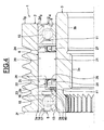
- the embodiment illustrated on the figure 4 differs in that the freewheel 6 is provided with an annular friction element 40 constituted by a body 41.
- the body 41 is advantageously made of synthetic material, for example polyamide, and overmolded on the radial portion 25 of the cage 22
- the generally annular body 41 comprises a bore in frictional contact with the outer surface 3a of the transmission element 3. It has a high coefficient of friction so as to be able to drive the transmission element 3 in rotation.
- a friction element 40 is mounted on the outer surface 3a of the inner transmission element 3 and comes into frictional contact with the cage 22.
- the pulley drives the central shaft when the engine accelerates or is in a substantially continuous mode or decelerates very slowly.
- the central axis of the disengageable pulley device can continue to rotate faster than the actual pulley thanks to the freewheel, thus sparing excessive stress on the drive belt.
- the freewheel allows an almost instantaneous transition from freewheel operation to torque-driven operation, and has good reliability over time.
Landscapes
- Engineering & Computer Science (AREA)
- General Engineering & Computer Science (AREA)
- Mechanical Engineering (AREA)
- Pulleys (AREA)
Claims (12)
- Ausrückbare Riemenscheibenvorrichtung, die eine auf ein inneres Übertragungselement (3) montierte Riemenscheibe (2) und ein Freilaufrad (6) enthält, das mit mehreren Klemmelementen versehen ist, die zwischen einen Gleitweg (20) der Riemenscheibe und einen Gleitweg (21) des inneren Übertragungselements montiert sind, wobei das Freilaufrad dazu bestimmt ist, ein unidirektionales Einrücken zwischen der Riemenscheibe (2) und dem inneren Übertragungselement (3) zu gewährleisten, wobei die ausrückbare Riemenscheibenvorrichtung mit einem Käfig (22) für die Klemmelemente, mit mindestens einem ringförmigen Reibungselement (30; 35; 40), das zwischen dem Käfig (22) und dem Gleitweg (21) des inneren Übertragungselements vorgesehen ist, um durch Reibung den Käfig und das innere Element zu verbinden, und mit mindestens einem elastischen Rückstellelement (29) versehen ist, das zwischen mindestens einem Klemmelement und dem Käfig angeordnet ist, wobei das elastische Rückstellelement (29) dahin tendiert, die Klemmelemente mit den Gleitwegen (20, 21) in einer eingerückten Stellung und in einer ausgerückten Stellung des Feilaufrads in Kontakt zu halten.
- Vorrichtung nach Anspruch 1, die einen einzigen Käfig (22) für die Klemmelemente aufweist.
- Vorrichtung nach Anspruch 1 oder 2, bei der in einer ausgerückten Stellung das innere Übertragungselement (3) dahin tendiert, das Feilaufrad (6) mittels des Reibungselements (30; 35; 40) und des Käfigs (22) im Wesentlichen mit gleicher Geschwindigkeit anzutreiben.
- Vorrichtung nach einem der vorhergehenden Ansprüche, bei der das ringförmige Reibungselement (30; 35; 40) auf den Käfig (22) montiert ist.
- Vorrichtung nach einem der vorhergehenden Ansprüche, die mindestens ein elastisches Rückstellelement (29) enthält, das zwischen jedem Klemmelement und dem Käfig angeordnet ist.
- Vorrichtung nach einem der vorhergehenden Ansprüche, bei der das elastische Rückstellelement (29) radial zwischen dem Käfig und dem inneren Übertragungselement angeordnet ist.
- Vorrichtung nach einem der vorhergehenden Ansprüche, bei der das ringförmige Reibungselement (30; 35; 40) auf einem radialen Abschnitt des Käfigs (22) angeordnet ist.
- Vorrichtung nach einem der vorhergehenden Ansprüche, bei der das Reibungselement (30; 35; 40) eine elastische Zone radial in Richtung einer Außenfläche des inneren Übertragungselements (3) enthält.
- Vorrichtung nach einem der vorhergehenden Ansprüche, bei der das Reibungselement (30) einen Reibungskörper (31) und einen Klemmring (32) des Körpers in Reibungskontakt enthält.
- Vorrichtung nach einem der Ansprüche 1 bis 8, bei der das ringförmige Reibungselement (35) eine Reibungslippe (37) enthält, die von einer radial elastischen Zone getragen wird.
- Vorrichtung nach einem der Ansprüche 1 bis 8, bei der das Reibungselement (40) aus einem Reibungskörper (41) besteht.
- Wechselstromgenerator, der eine Welle und eine ausrückbare Riemenscheibenvorrichtung nach einem der vorhergehenden Ansprüche aufweist, die auf die Welle montiert ist.
Applications Claiming Priority (1)
| Application Number | Priority Date | Filing Date | Title |
|---|---|---|---|
| FR0654082A FR2906858B1 (fr) | 2006-10-04 | 2006-10-04 | Dispositif de poulie debrayable. |
Publications (2)
| Publication Number | Publication Date |
|---|---|
| EP1908980A1 EP1908980A1 (de) | 2008-04-09 |
| EP1908980B1 true EP1908980B1 (de) | 2011-08-03 |
Family
ID=37964011
Family Applications (1)
| Application Number | Title | Priority Date | Filing Date |
|---|---|---|---|
| EP07116412A Not-in-force EP1908980B1 (de) | 2006-10-04 | 2007-09-14 | Vorrichtung mit ausrückbarer Riemenscheibe |
Country Status (5)
| Country | Link |
|---|---|
| US (1) | US20080090686A1 (de) |
| EP (1) | EP1908980B1 (de) |
| JP (1) | JP5389344B2 (de) |
| CN (1) | CN101178099B (de) |
| FR (1) | FR2906858B1 (de) |
Families Citing this family (8)
| Publication number | Priority date | Publication date | Assignee | Title |
|---|---|---|---|---|
| WO2007043650A1 (ja) * | 2005-10-14 | 2007-04-19 | Jtekt Corporation | プーリ装置、及びオートテンショナ |
| FR2902699B1 (fr) | 2006-06-26 | 2010-10-22 | Skf Ab | Dispositif de butee de suspension et jambe de force. |
| FR2906587B1 (fr) | 2006-10-03 | 2009-07-10 | Skf Ab | Dispositif de galet tendeur. |
| FR2913081B1 (fr) | 2007-02-27 | 2009-05-15 | Skf Ab | Dispositif de poulie debrayable |
| DE102008030017B4 (de) * | 2008-06-24 | 2016-07-21 | Schaeffler Technologies AG & Co. KG | Metallkäfige für Klemmkörperfreilaufkupplungen |
| DE102010032665A1 (de) * | 2009-08-06 | 2011-02-10 | Schaeffler Technologies Gmbh & Co. Kg | Freilauf, insbesondere für ein Kurbel-CVT-Getriebe |
| DE102013202699A1 (de) * | 2013-02-20 | 2014-08-21 | Schaeffler Technologies Gmbh & Co. Kg | Riemenscheibenanordnung für einen Riementrieb zum Antrieb von Nebenaggregaten eines Kraftfahrzeugs und Verfahren zum Antrieb eines über eine Riemenscheibenanordnung angebundenen Nebenaggregats eines Kraftfahrzeugs |
| DE102019133200B3 (de) * | 2019-12-05 | 2021-03-11 | Schaeffler Technologies AG & Co. KG | Rollenfreilaufeinheit für ein Fahrzeug, Fahrzeug mit einer Rollenfreilaufeinheit sowie Verwendung und Verfahren zur Montage der Rollenfreilaufeinheit |
Family Cites Families (106)
| Publication number | Priority date | Publication date | Assignee | Title |
|---|---|---|---|---|
| US1368068A (en) * | 1920-05-29 | 1921-02-08 | Stein Louis | Hose-coupling |
| CH89090A (de) * | 1934-02-12 | 1921-04-16 | Messerli Johann | Werkzeughalter. |
| US2140975A (en) * | 1936-10-27 | 1938-12-20 | William T Welch | Clutch mechanism |
| US2576337A (en) * | 1947-01-25 | 1951-11-27 | Ford Motor Co | Overrunning sprag type clutch |
| US2630896A (en) * | 1951-08-02 | 1953-03-10 | Adiel Y Dodge | One-way clutch |
| US2940568A (en) * | 1957-03-25 | 1960-06-14 | Borg Warner | One-way clutch and drag spring |
| US3008362A (en) * | 1959-03-20 | 1961-11-14 | Babcock & Wilcox Co | Power operated stud tensioners |
| US3258962A (en) * | 1963-02-14 | 1966-07-05 | Asea Ab | Magneto-elastic force measuring device |
| US3365967A (en) * | 1965-06-07 | 1968-01-30 | Moogk Friedrich | Stepless variable v-belt driving gear with asymmetric v-belt |
| US3545581A (en) * | 1968-12-19 | 1970-12-08 | Borg Warner | Sprag assembly for one-way clutches |
| US3702649A (en) * | 1970-01-31 | 1972-11-14 | Ringspann Maurer Kg A | One-way clutch having tiltable sprags |
| US3743066A (en) * | 1972-07-05 | 1973-07-03 | Skf Cie Applic Mecanique | Free wheel drive |
| DE2361916C2 (de) * | 1973-12-13 | 1975-03-06 | Stieber Division Der Borg-Warner Gmbh, 6900 Heidelberg | Klemmkörper-Freilaufkupplung |
| FR2304829A1 (fr) * | 1975-03-21 | 1976-10-15 | Ferodo Sa | Butee de debrayage |
| US4020720A (en) * | 1975-06-04 | 1977-05-03 | Kaneharu Fujii | Apparatus for tightening high-strength steel bolts |
| US3965565A (en) * | 1975-06-04 | 1976-06-29 | Kaneharu Fujii | Method of and apparatus for tightening high-strength steel bolts |
| US3997041A (en) * | 1975-09-19 | 1976-12-14 | Borg-Warner Corporation | One-way clutch |
| US4046238A (en) * | 1976-02-03 | 1977-09-06 | Mendoza Orozco Hector | Free-wheeling mechanism for bicycles |
| CH614960A5 (de) * | 1976-04-15 | 1979-12-28 | Ciba Geigy Ag | |
| US4319220A (en) * | 1976-08-31 | 1982-03-09 | Dennis G. Pappas | Alarm system for monitoring pressurized vehicular tires |
| DE2718602A1 (de) * | 1977-04-22 | 1978-10-26 | Kraftwerk Union Ag | Vorrichtung zum spannen mehrerer schraubenbolzen |
| DE2758841C2 (de) * | 1977-12-30 | 1986-09-04 | Stieber Division Der Borg-Warner Gmbh, 6900 Heidelberg | Klemmkörper-Freilaufkupplung |
| CH631013A5 (de) * | 1978-09-20 | 1982-07-15 | Schmid Roost J Sro Kugellagerw | Messvorrichtung. |
| US4505484A (en) * | 1980-03-12 | 1985-03-19 | Nippon Seiko Kabushiki Kaisha | Sealing device for a rolling bearing |
| JPS57161344A (en) * | 1981-03-27 | 1982-10-04 | Nippon Denso Co Ltd | Belt tension control device |
| DE3117162C2 (de) * | 1981-04-30 | 1983-02-17 | Skf Kugellagerfabriken Gmbh, 8720 Schweinfurt | "Verfahren zur paarweisen Herstellung von kunststoffumspritzten Laufringen für Wälzlager" |
| US4438901A (en) * | 1982-01-25 | 1984-03-27 | Gripper, Inc. | Apparatus for tensioning a stud and method of doing same |
| US4523742A (en) * | 1982-01-25 | 1985-06-18 | Gripper, Inc. | Apparatus for tensioning a stud and method of doing same |
| JPS58145522A (ja) * | 1982-02-20 | 1983-08-30 | Honda Motor Co Ltd | 車両用動力伝達装置 |
| JPS58163832A (ja) * | 1982-03-24 | 1983-09-28 | Tsubakimoto Moorusu:Kk | 一方向クラツチ |
| JPS58151743U (ja) * | 1982-04-06 | 1983-10-11 | アイシン精機株式会社 | シリンダ装置用ピストン |
| US4601374A (en) * | 1982-04-22 | 1986-07-22 | Federal-Mogul Corporation | Hydraulic clutch piston and seal |
| US4497523A (en) * | 1983-02-28 | 1985-02-05 | General Motors Corporation | Modular suspension strut bearing |
| FR2544429B1 (fr) * | 1983-04-15 | 1985-08-02 | Valeo | Procede pour le montage d'une butee de debrayage, et butee de debrayage correspondante, notamment pour vehicule automobile |
| DE3445541A1 (de) * | 1984-01-04 | 1985-07-11 | Skandiafabriken AB, Mullsjö | Fluessigkeits-fuellstandsanzeiger |
| US4708036A (en) * | 1984-02-07 | 1987-11-24 | Haskel, Inc. | Stud tensioning apparatus |
| US4541744A (en) * | 1984-11-15 | 1985-09-17 | General Motors Coporation | Unitized bearing assembly with moldable race members and labryinth seal |
| US5033013A (en) * | 1985-04-22 | 1991-07-16 | Yamasa Tokei Meter Co., Ltd. | Method and apparatus for measuring the amount of exercise |
| US4699530A (en) * | 1985-06-28 | 1987-10-13 | Oiless Industry Co., Ltd. | Thrust ball bearing unit |
| US4602875A (en) * | 1985-11-18 | 1986-07-29 | General Motors Corporation | Combined bearing, rotatable member and shield assembly |
| US4756395A (en) * | 1985-12-03 | 1988-07-12 | Dana Corporation | Overrunning clutch with controlled sprag action |
| GB2194638B (en) * | 1986-03-27 | 1990-01-10 | Protos Precision Systems Ltd | Shapemeter |
| JPH0633223Y2 (ja) * | 1986-05-16 | 1994-08-31 | 本田技研工業株式会社 | ワンウエイクラツチ |
| FR2599794B1 (fr) * | 1986-06-10 | 1991-06-07 | Roulements Soc Nouvelle | Palier ou roulement a capteur d'informations |
| JPH0313625Y2 (de) * | 1986-12-10 | 1991-03-28 | ||
| DE3765236D1 (de) * | 1986-12-22 | 1990-10-31 | Siemens Ag | Winkellagegeber mit fotoelektrisch abtastbarer geberscheibe und zweifach gelagerter geberwelle. |
| FR2609126B1 (fr) * | 1986-12-29 | 1989-10-27 | Valeo | Butee de debrayage, notamment pour vehicule automobile |
| FR2611009B1 (fr) * | 1987-02-17 | 1989-05-19 | Valeo | Butee de debrayage, notamment pour vehicule automobile |
| JPS63246516A (ja) * | 1987-04-02 | 1988-10-13 | Nippon Seiko Kk | クラツチレリ−ズ軸受装置 |
| US4722617A (en) * | 1987-07-17 | 1988-02-02 | The Torrington Company | Ball bearing assembly |
| DE3729632A1 (de) * | 1987-09-04 | 1989-03-16 | Schaeffler Waelzlager Kg | Freilaufkupplung mit klemmkoerpern |
| US4815867A (en) * | 1987-09-23 | 1989-03-28 | Federal-Mogul Corporation | Side assembled clip for self-aligning bearing |
| DE3742030C2 (de) * | 1987-12-11 | 1997-06-19 | Skf Gmbh | Schwenklager für Spannvorrichtungen |
| JPH01188726A (ja) * | 1988-01-21 | 1989-07-28 | Nsk Warner Kk | ワンウェイクラッチ用保持器 |
| DE8810259U1 (de) * | 1988-08-12 | 1988-11-17 | Messer Griesheim Gmbh, 6000 Frankfurt | Spülblock |
| GB8823474D0 (en) * | 1988-10-06 | 1988-11-16 | Hedley Purvis Ltd | Improved hydraulic tensioner |
| FR2640706B1 (fr) * | 1988-12-20 | 1991-02-01 | Roulements Soc Nouvelle | Roulement a capteur d'informations |
| US5008647A (en) * | 1989-02-06 | 1991-04-16 | Orleander S.A. | Wireless bicycle wheel monitor system |
| US4915512A (en) * | 1989-03-24 | 1990-04-10 | The Torrington Company | Thrust bearing with a magnetic field sensor |
| US5017741A (en) * | 1989-03-29 | 1991-05-21 | Hamilton Standard Controls, Inc. | Rotary digital contact encoder substrate |
| US4970945A (en) * | 1989-04-28 | 1990-11-20 | General Motors Corporation | Actuating piston assembly, and seal therefor, for torque transmitting systems |
| US5018384A (en) * | 1989-07-21 | 1991-05-28 | Nippon Seiko Kabushiki Kaisha | Rotational speed detector |
| IT1240481B (it) * | 1990-07-04 | 1993-12-17 | Skf Ind Spa | Dispositivo atto a permettere la rilevazione della velocita' di rotazione tra due organi in rotazione relativa quali gli organi di sopporto di una ruota di un veicolo. |
| DE4015028A1 (de) * | 1990-05-10 | 1992-01-16 | Skf Gmbh | Voreinstellbare spannvorrichtung |
| US5051693A (en) * | 1990-09-07 | 1991-09-24 | The Torrington Company | Bearing seat encoder mount for rotational parameter sensor apparatus |
| DE4036024C1 (de) * | 1990-11-13 | 1992-02-27 | Heidelberger Druckmaschinen Ag, 6900 Heidelberg, De | |
| IT1256785B (it) * | 1992-01-28 | 1995-12-15 | Skf Ind Spa | Complesso di tenuta con un dispositivo sensore a bordo, per un cuscinetto di rotolamento. |
| DE4233896C2 (de) * | 1992-10-08 | 1995-06-08 | Bosch Gmbh Robert | Kolben |
| FR2700588B1 (fr) * | 1993-01-19 | 1995-02-17 | Roulements Soc Nouvelle | Dispositif de montage à joint d'étanchéité à codeur incorporé. |
| FR2712048B1 (fr) * | 1993-11-04 | 1995-12-15 | Roulements Soc Nouvelle | Joint d'étanchéité pour roulements à capteur d'informations et roulement ainsi équipé. |
| DE4408873C2 (de) * | 1994-03-16 | 1999-02-11 | Westfalia Nukleartechnik Gmbh | Schraubenspannvorrichtung, insbesondere für Deckelverschraubungen, wie vor allem bei Reaktordruckbehältern |
| US5454585A (en) * | 1994-08-08 | 1995-10-03 | General Motors Corporation | Strut assembly with bearing axis alignment |
| JPH08140308A (ja) * | 1994-11-10 | 1996-05-31 | Mitsubishi Electric Corp | 車両用充電発電機 |
| DE19503469C1 (de) * | 1995-02-03 | 1996-05-30 | Freudenberg Carl Fa | Dichtungsanordnung |
| FR2730534B1 (fr) * | 1995-02-09 | 1997-04-04 | Valeo | Butee de debrayage a commande hydraulique pour un embrayage a diaphragme de vehicule automobile |
| FR2730566B1 (fr) * | 1995-02-09 | 1997-06-13 | Skf France | Dispositif de codeur pour capteur de vitesse de rotation et roulement equipe d'un tel dispositif |
| DE19506144C1 (de) * | 1995-02-22 | 1996-05-30 | Rasmussen Gmbh | Vorrichtung zum Festklemmen eines auf einem Rohrendabschnitt aufgeschobenen Schlauchendabschnitts |
| US5592401A (en) * | 1995-02-28 | 1997-01-07 | Virtual Technologies, Inc. | Accurate, rapid, reliable position sensing using multiple sensing technologies |
| JPH08292111A (ja) * | 1995-04-24 | 1996-11-05 | Mitsubishi Electric Corp | ベルト張力測定装置 |
| US5598913A (en) * | 1995-06-07 | 1997-02-04 | Ntn Corporation | One-way over-running clutch pulley |
| US5657544A (en) * | 1995-09-26 | 1997-08-19 | Ntn Corporation | Device for detecting the angle of rotation |
| US6011491A (en) * | 1995-10-10 | 2000-01-04 | Goetzl; Brent A. | Speedometer for in-line skates |
| US5721539A (en) * | 1995-10-10 | 1998-02-24 | Goetzl; Brent A. | Speedometer for in-line skates |
| US5845230A (en) * | 1996-01-30 | 1998-12-01 | Skf Condition Monitoring | Apparatus and method for the remote monitoring of machine condition |
| DE19614385A1 (de) * | 1996-03-04 | 1997-09-11 | Schaeffler Waelzlager Kg | Dichtung für einen Ringkolben einer hydraulischen Kupplungs-Ausrückvorrichtung |
| DE69723237T2 (de) * | 1996-03-08 | 2004-05-27 | Koyo Seiko Co., Ltd. | Scheibe mit verstellbarem durchmesser |
| US5780731A (en) * | 1996-04-11 | 1998-07-14 | Denso Corporation | Method for judging the locked state of auxiliaries for automobiles |
| US6025737A (en) * | 1996-11-27 | 2000-02-15 | Altera Corporation | Circuitry for a low internal voltage integrated circuit |
| FR2754903B1 (fr) * | 1996-10-23 | 1998-12-04 | Skf France | Dispositif de codeur pour capteur de vitesse de rotation et roulement equipe d'un tel dispositif |
| DE19716218C2 (de) * | 1997-04-18 | 2001-08-30 | Schaeffler Waelzlager Ohg | Kupplungsausrücklager |
| ATE248300T1 (de) * | 1997-05-07 | 2003-09-15 | Litens Automotive Inc | Riemenantriebssystem mit generatorverbindungsfreilaufkupplung |
| EP0916074B1 (de) * | 1997-05-29 | 2003-07-30 | AMS International AG | Magnetischer drehgeber |
| JPH11117955A (ja) * | 1997-10-13 | 1999-04-27 | Nsk Warner Kk | 一方向クラッチ |
| DE29720776U1 (de) * | 1997-11-22 | 1998-01-15 | Skf Gmbh, 97421 Schweinfurt | Befestigungsvorrichtung für Riemenrollen |
| FR2772920B1 (fr) * | 1997-12-18 | 2000-02-04 | Skf France | Montage de roue de patin en ligne avec dispositif de detection de la vitesse de rotation |
| JP4051114B2 (ja) * | 1997-12-22 | 2008-02-20 | Nskワーナー株式会社 | スプラグ型ワンウェイクラッチ |
| US6013007A (en) * | 1998-03-26 | 2000-01-11 | Liquid Spark, Llc | Athlete's GPS-based performance monitor |
| FR2779096B1 (fr) * | 1998-05-28 | 2000-12-15 | Skf France | Dispositif de butee de suspension |
| US6196552B1 (en) * | 1998-06-08 | 2001-03-06 | Automotive Products (Usa), Inc. | Seal assembly for annular hydraulic cylinder |
| US6155543A (en) * | 1999-01-27 | 2000-12-05 | Daimlerchrysler Corporation | Spring seat assembly for an automotive vehicle |
| JP2000297860A (ja) * | 1999-02-12 | 2000-10-24 | Nsk Ltd | オルタネータ用ローラクラッチ内蔵型プーリ装置 |
| US6160480A (en) * | 1999-09-24 | 2000-12-12 | Su-Yueh; Hsien Huang | Wireless inline-skate and skate board pulse watch with speed and heart rate monitoring |
| KR100799792B1 (ko) * | 2000-03-28 | 2008-01-31 | 닛뽄 세이꼬 가부시기가이샤 | 일방향 클러치 내장형 회전 전달 장치 |
| US6892868B2 (en) * | 2001-07-05 | 2005-05-17 | Koyo Seiko Co., Ltd. | One-way clutch |
| FR2856759B1 (fr) | 2003-06-30 | 2006-07-14 | Skf France | Dispositif et cage de roue libre. |
| JP2005282856A (ja) | 2004-03-02 | 2005-10-13 | Ntn Corp | 一方向クラッチおよび軸受複合一方向クラッチ |
-
2006
- 2006-10-04 FR FR0654082A patent/FR2906858B1/fr not_active Expired - Fee Related
-
2007
- 2007-09-14 EP EP07116412A patent/EP1908980B1/de not_active Not-in-force
- 2007-10-02 US US11/866,299 patent/US20080090686A1/en not_active Abandoned
- 2007-10-03 JP JP2007259914A patent/JP5389344B2/ja not_active Expired - Fee Related
- 2007-10-08 CN CN2007101944689A patent/CN101178099B/zh not_active Expired - Fee Related
Also Published As
| Publication number | Publication date |
|---|---|
| FR2906858A1 (fr) | 2008-04-11 |
| JP5389344B2 (ja) | 2014-01-15 |
| EP1908980A1 (de) | 2008-04-09 |
| CN101178099A (zh) | 2008-05-14 |
| CN101178099B (zh) | 2011-12-07 |
| FR2906858B1 (fr) | 2008-12-05 |
| JP2008089182A (ja) | 2008-04-17 |
| US20080090686A1 (en) | 2008-04-17 |
Similar Documents
| Publication | Publication Date | Title |
|---|---|---|
| EP1908980B1 (de) | Vorrichtung mit ausrückbarer Riemenscheibe | |
| FR2914381A1 (fr) | Dispositif de poulie debrayable. | |
| FR2913081A1 (fr) | Dispositif de poulie debrayable | |
| EP1651878B1 (de) | Freilauflagervorrichtung mit drehmomentbegrenzer | |
| EP1061278A1 (de) | Befestigungsvorrichtung für eine Laufrolle und Laufrolle mit einer solchen Vorrichtung | |
| FR2932863A1 (fr) | Dispositif de poulie pour galet tendeur ou enrouleur. | |
| FR2981715A1 (fr) | Systeme d'amortissement de type oscillateur pendulaire comportant un dispositif de guidage perfectionne | |
| FR2954437A1 (fr) | Dispositif de poulie pour galet tendeur ou enrouleur. | |
| FR2922605A1 (fr) | Module debrayable pour systeme de transmission d'un couple de demarrage a un moteur a combustion interne | |
| FR2906329A1 (fr) | Structure de dispositif de transmission de couple de demarrage de moteur equipe d'un embrayage a galets | |
| FR2915778A1 (fr) | Dispositif de palier a roulement pour colonne de direction | |
| FR3006711A1 (fr) | Systeme d'entrainement de pompe a eau et procede de montage | |
| FR2858377A1 (fr) | Dispositif de roue libre | |
| FR2961280A1 (fr) | Dispositif de butee de debrayage comprenant une bague d'usure. | |
| FR2936032A1 (fr) | Roulement, son utilisation et vehicule automobile equipe d'un tel roulement. | |
| EP1639267B9 (de) | Vorrichtung und freilaufgehäuse | |
| EP1900958B1 (de) | Vorrichtung mit ausrückbarer Riemenscheibe | |
| FR2933460A1 (fr) | Dispositif de poulie debrayable | |
| FR2939855A1 (fr) | Roue libre pour dispositif de poulie debrayable | |
| EP1500838B1 (de) | Freilaufvorrichtung, Riemenscheibe und Generator mit einem Freilauf | |
| FR2938033A1 (fr) | Dispositif de poulie debrayable | |
| FR3038028A1 (fr) | Dispositif de galet tendeur | |
| FR2866085A1 (fr) | Dispositif de buee axiale de volant d'inertie. | |
| FR2897127A1 (fr) | Dispositif de blocage en rotation, palier a roulement et machie tournante. | |
| FR2816017A1 (fr) | Cage de maitien d'elements de coincement pour dispositif de roue libre et dispositif de roue libre |
Legal Events
| Date | Code | Title | Description |
|---|---|---|---|
| PUAI | Public reference made under article 153(3) epc to a published international application that has entered the european phase |
Free format text: ORIGINAL CODE: 0009012 |
|
| AK | Designated contracting states |
Kind code of ref document: A1 Designated state(s): AT BE BG CH CY CZ DE DK EE ES FI FR GB GR HU IE IS IT LI LT LU LV MC MT NL PL PT RO SE SI SK TR |
|
| AX | Request for extension of the european patent |
Extension state: AL BA HR MK RS |
|
| RIN1 | Information on inventor provided before grant (corrected) |
Inventor name: GARDELLE, JEAN-LUC Inventor name: ARNAULT, BENOIT Inventor name: CLAUDE, FRANCIS |
|
| 17P | Request for examination filed |
Effective date: 20080728 |
|
| 17Q | First examination report despatched |
Effective date: 20080916 |
|
| AKX | Designation fees paid |
Designated state(s): DE FR IT |
|
| R17C | First examination report despatched (corrected) |
Effective date: 20090520 |
|
| GRAC | Information related to communication of intention to grant a patent modified |
Free format text: ORIGINAL CODE: EPIDOSCIGR1 |
|
| GRAP | Despatch of communication of intention to grant a patent |
Free format text: ORIGINAL CODE: EPIDOSNIGR1 |
|
| GRAS | Grant fee paid |
Free format text: ORIGINAL CODE: EPIDOSNIGR3 |
|
| GRAA | (expected) grant |
Free format text: ORIGINAL CODE: 0009210 |
|
| AK | Designated contracting states |
Kind code of ref document: B1 Designated state(s): DE FR IT |
|
| REG | Reference to a national code |
Ref country code: DE Ref legal event code: R096 Ref document number: 602007016230 Country of ref document: DE Effective date: 20111006 |
|
| PG25 | Lapsed in a contracting state [announced via postgrant information from national office to epo] |
Ref country code: IT Free format text: LAPSE BECAUSE OF FAILURE TO SUBMIT A TRANSLATION OF THE DESCRIPTION OR TO PAY THE FEE WITHIN THE PRESCRIBED TIME-LIMIT Effective date: 20110803 |
|
| PLBE | No opposition filed within time limit |
Free format text: ORIGINAL CODE: 0009261 |
|
| STAA | Information on the status of an ep patent application or granted ep patent |
Free format text: STATUS: NO OPPOSITION FILED WITHIN TIME LIMIT |
|
| 26N | No opposition filed |
Effective date: 20120504 |
|
| REG | Reference to a national code |
Ref country code: DE Ref legal event code: R119 Ref document number: 602007016230 Country of ref document: DE Effective date: 20120403 |
|
| PG25 | Lapsed in a contracting state [announced via postgrant information from national office to epo] |
Ref country code: DE Free format text: LAPSE BECAUSE OF NON-PAYMENT OF DUE FEES Effective date: 20120403 |
|
| REG | Reference to a national code |
Ref country code: FR Ref legal event code: PLFP Year of fee payment: 9 |
|
| PGFP | Annual fee paid to national office [announced via postgrant information from national office to epo] |
Ref country code: FR Payment date: 20150928 Year of fee payment: 9 |
|
| REG | Reference to a national code |
Ref country code: FR Ref legal event code: ST Effective date: 20170531 |
|
| PG25 | Lapsed in a contracting state [announced via postgrant information from national office to epo] |
Ref country code: FR Free format text: LAPSE BECAUSE OF NON-PAYMENT OF DUE FEES Effective date: 20160930 |