EP1908980B1 - Disconnectable pulley device - Google Patents
Disconnectable pulley device Download PDFInfo
- Publication number
- EP1908980B1 EP1908980B1 EP07116412A EP07116412A EP1908980B1 EP 1908980 B1 EP1908980 B1 EP 1908980B1 EP 07116412 A EP07116412 A EP 07116412A EP 07116412 A EP07116412 A EP 07116412A EP 1908980 B1 EP1908980 B1 EP 1908980B1
- Authority
- EP
- European Patent Office
- Prior art keywords
- cage
- pulley
- friction
- freewheel
- inner transmission
- Prior art date
- Legal status (The legal status is an assumption and is not a legal conclusion. Google has not performed a legal analysis and makes no representation as to the accuracy of the status listed.)
- Expired - Fee Related
Links
Images

Classifications
-
- F—MECHANICAL ENGINEERING; LIGHTING; HEATING; WEAPONS; BLASTING
- F16—ENGINEERING ELEMENTS AND UNITS; GENERAL MEASURES FOR PRODUCING AND MAINTAINING EFFECTIVE FUNCTIONING OF MACHINES OR INSTALLATIONS; THERMAL INSULATION IN GENERAL
- F16D—COUPLINGS FOR TRANSMITTING ROTATION; CLUTCHES; BRAKES
- F16D41/00—Freewheels or freewheel clutches
- F16D41/06—Freewheels or freewheel clutches with intermediate wedging coupling members between an inner and an outer surface
- F16D41/069—Freewheels or freewheel clutches with intermediate wedging coupling members between an inner and an outer surface the intermediate members wedging by pivoting or rocking, e.g. sprags
- F16D41/07—Freewheels or freewheel clutches with intermediate wedging coupling members between an inner and an outer surface the intermediate members wedging by pivoting or rocking, e.g. sprags between two cylindrical surfaces
Definitions
- the present invention relates to the field of freewheels.
- the present invention relates to the field of disengageable pulleys equipped with freewheels used for example in the drive pulleys of alternators in a motor vehicle.
- Such disengageable pulleys are known in themselves and are increasingly used to remedy the adverse effects of sudden motor acyclisms or decelerations that occur in internal combustion engines, particularly at low speeds and especially in diesel engines.
- a drive belt which is connected to the engine by means of a crankshaft pulley, can suddenly decelerate while a driven pulley, for example a pulley of the alternator, tends, by inertia, to keep turning at the same speed.
- Such variations generate adverse effects such as abnormal belt fatigue with risk of rupture, a sliding thereof on the pulley, or a vibration of the belt strands between the pulleys.
- a freewheel has been incorporated between the driven pulley and the driven shaft which makes it possible to temporarily disconnect the pulley from the shaft in the event of sudden deceleration of said pulley.
- Such a disengageable pulley is known in particular by the document JP 2005-282856 and generally comprises two bearings disposed on each side of the pulley, and a free wheel mounted between the two bearings and provided with a plurality of jamming cams and a cage having a plurality of windows for housing said cams.
- this document provides for fixing the holding cage on the driven shaft in order to drive the cage and the shaft at the same angular speed. In this way, when the pulley is in the disengaged position in which it operates freewheeling, there is a slip only between the cams and a sliding path located inside the pulley which is properly lubricated by the centrifugal force. which tends to project the lubricant to the outside.
- the cage has no degree of angular freedom with respect to the driven shaft.
- the Applicant has found that this can adversely affect the operational safety of the freewheel notably by causing risks of interference between the cams and the edges of the windows of the holding cage when the cams tilt.
- Such a device has the disadvantage of using two holding cages, one of which is provided with friction elements which are made in the form of clips, which increases the cost price of the device.
- the device may be lacking, for certain applications, responsiveness to quickly move from a freewheel operation to an operation in couple. This is particularly the case for an application on an alternator in which the acyclisms result in extremely rapid variations in the rotational speed of the engine.
- the present invention therefore aims to overcome the aforementioned drawbacks.
- the present invention is intended in particular to provide a disengageable pulley in which it would be possible to move more quickly from a freewheel position to a position in torque, and vice versa.
- the present invention also aims to provide a disengageable pulley which comprises economic components to manufacture and assemble.
- the present invention aims to provide a disengageable pulley with good reliability.
- the disengagable pulley device comprises a pulley mounted on an inner transmission member, and a freewheel provided with a plurality of wedging elements, such as cams, mounted between a sliding path of the pulley and a sliding path. of the inner transmission element. Said free wheel is intended to ensure a unidirectional clutch between the pulley and the inner transmission element.
- the device is provided with a cage for the wedging elements, at least one annular friction element provided between the cage and the sliding path of the inner transmission element for frictionally connecting the cage and the inner element. transmission, and at least one elastic return element disposed between at least one wedging element and the cage, the elastic return element tending to keep the wedging elements in contact with the sliding paths during a position engaged and in a disengaged position of the freewheel.
- the elastic return element is disposed between the wedging element and the cage which is driven by the inner transmission element, thanks to the friction element.
- the Applicant has determined that the relative provision of the elastic return element and the cage allows in particular to tend to maintain a permanent contact between the sliding paths of the device in the engaged position and in the disengaged position.
- the annular friction element provided between the cage and the sliding path of the inner transmission element tends to cause the freewheeling through said cage at the same speed as the inner transmission element as long as a drag torque due to friction of the wedging elements on the slip path of the pulley is less than the frictional torque between the friction element and the part on which it is intended to rub, ie the cage or the inner transmission element.
- the frictional coupling between the cage and the inner transmission element may also allow the cage to rotate slightly with respect to the inner element, for example in the case where the wedging elements would force against the edges of the housing. alveoli or windows when tilting. Indeed, under these conditions, the wedging elements tend to rotate the cage which can move angularly relative to the inner transmission element. This prevents jamming of the wedging elements by the cage, or deterioration of said cage. This further promotes a good operation of the freewheel.
- the annular friction element is distinct from the elastic return element associated with at least one of the wedging elements.
- a friction element makes it possible to provide, on the part intended to be driven, a surface of substantially flat contact and without projecting elements forming meshing teeth requiring adjustment during assembly.
- the pulley comprises a single cage for the wedging elements.
- the cage is monobloc.
- the freewheel is devoid of an additional cage of different radius to that of the cage and capable of tilting the cams of the engaged position.
- the friction element is circumferentially continuous.
- the inner transmission element tends to drive the free wheel substantially at the same speed, through the friction element and the cage.
- the annular friction element is mounted on the cage.
- At least one elastic return element is disposed between each wedging element and the cage.
- the elastic return element is disposed radially between the cage and the inner transmission element.
- the freewheel includes engaging cams.
- the slip path of the inner transmission member for the wedging members is formed directly by an outer surface of said inner transmission member.
- the sliding path of the pulley for the wedging elements is formed directly by a bore of said pulley.
- the annular friction element may comprise an elastic zone radially towards an outer surface of the inner transmission element.
- the annular friction element is disposed on a radial portion of the cage.
- the annular friction element is disposed on an axial portion of the cage.
- the annular friction element comprises a friction body and a clamping ring of the body in frictional contact.
- the annular friction element may comprise a friction lip supported by a radially elastic zone.
- the friction element consists of a friction body.
- the friction element can be attached to the cage.
- the friction element is distinct from the cage. It is also possible to provide the friction element and the one-piece cage.
- the device comprises at least two bearings, the freewheel being arranged axially between the bearings.
- the disengagable pulley device may be mounted on an alternator shaft for driving said alternator.
- the pulley can be mounted on a central shaft, in particular by means of a freewheel.
- the drive shaft can be mounted on the alternator shaft.
- a drive belt driven by the motor may come to bear on a periphery of the pulley.
- the pulley drives the central shaft when the motor accelerates or is in a substantially continuous mode or decelerates very slowly.
- the central axis of the disengagable pulley device can continue to rotate faster than the actual pulley thanks to the freewheel, thus sparing excessive stresses on the drive belt.
- the invention tends to keep the wedging elements in constant contact with the sliding paths during an engaged position and in a disengaged position of the freewheel, which allows in particular to pass almost instantaneously from a freewheel position to a torque-engaged position, and vice versa.
- the invention also makes it possible and to limit the wear of the wedging elements which slide mainly on the outer track of the pulley which is perfectly lubricated during the rotation of the device.
- the disengageable pulley device 1 comprises a pulley 2, an inner transmission element 3, for example a hollow shaft, two rolling bearings 4 and 5, and a free wheel 6.
- the pulley 2, of axis 7, has an outer surface provided with a grooved zone 2a with annular grooves and an axial zone 2b formed at an axial end of the grooved zone 2a.
- the pulley 2 comprises a cylindrical bore 2c extending over the entire length of the pulley 2, with the exception of chamfers 2d and 2e each disposed at one axial end, and two radial front surfaces 2f and 2g.
- the inner transmission element 3 which is in the form of a hollow shaft, has a cylindrical axial outer surface 3a on which is provided at each of the axial ends, a chamfer (not referenced).
- the inner transmission element 3 also has a bore 3b, a portion 3c has a thread for attachment to the end of an alternator shaft and the drive of said shaft (not shown).
- the bearing 4 coaxial with the axis 7, comprises an inner ring 8, an outer ring 9, between which are housed a row of rolling elements 10 made here in the form of balls, a cage 11 for maintaining the circumferential space rolling elements 10, and a seal 12.
- the inner ring 8 comprises a bore 8a of cylindrical shape, fitted with the outer surface 3a of the inner transmission element 3, and delimited by two radial side surfaces 8b and 8c opposite, and an outer cylindrical surface 8d staged from which is formed a circular groove 8e having in cross section a concave internal profile adapted to form a raceway for the rolling elements 10, said groove being oriented outwardly.
- the outer ring 9 comprises an outer cylindrical surface 9a fitted into the bore 2c of the pulley 2 and delimited by front surfaces 9b and 9c, and a stepped bore 9d of cylindrical shape from which is formed a circular groove 9e having in cross section a concave internal profile adapted to form a raceway for the rolling elements 10 facing inwards .
- the bore 9d here comprises two annular grooves (not referenced) symmetrical to each other with respect to a plane passing through the center of the rolling elements 10. Inside the annular groove located on the outside of the bearing 4 is mounted the seal sealing 12 which rubs against the cylindrical outer surface 8d of the inner ring 8 to form a seal.
- the seal 12 is arranged radially between the inner and outer rings 8, 9, and mounted axially between the rolling elements 10 and the radial surfaces 8b and 9b of the rings 8 and 9. Said surfaces are flush with the axial radial front surface 2g pulley 2.
- the bearing 5, coaxial with the axis 7, comprises an inner ring 13 fitted with the outer surface 3a of the inner transmission element 3, an outer ring 14 fitted into the bore 2c of the pulley 2, between which are housed a row of rolling elements 15 made here in the form of balls, a cage 16 for maintaining the circumferential space of the rolling elements 15, and a metal seal 17.
- the bearing 5 is identical to the bearing 4, and is arranged symmetrically with respect to it by considering a radial plane passing through the center of the pulley 2. The bearing 5 is thus flush with the axial radial front surface 2f of the pulley. 2.
- the bearings 4 and 5 are therefore arranged at each axial end of the pulley 2, the free wheel 6 being mounted axially between them. Freewheel 6 thus benefits from protection against intrusion foreign elements through the bearings 4 and 5, including seals 12 and 17.
- the free wheel 6 comprises a plurality of wedging elements or cams 19 arranged between two sliding paths 20 and 21, cylindrical in shape of revolution.
- the cams 19 are of the "engaging" type, that is to say having a tendency, under the effect of centrifugal forces during the rotation of the freewheel, to swing in the direction favoring their locking between the two sliding paths. 20 and 21, in order to facilitate an almost instantaneous transition from freewheel operation to torque-driven operation.
- the sliding path 20 is formed by the bore 2c of the pulley 2.
- the sliding path 21 is formed by the axial outer surface 3a of the shaft 3.
- the pulley 2 can be manufactured with an inner surface of particularly simple form entirely axial except for the chamfers 2d and 2e end.
- the pulley 2 can be obtained at low cost.
- This inner surface constitutes an outer surface for the cams 19, or of large diameter.
- the sliding path 21 is formed on the outer surface 3a of the shaft 3.
- the outer profile of revolution of the shaft 3 has the same diameter along its entire length. The finishing can be carried out in a single operation on a grinding machine and makes it possible to obtain, in large numbers and at low cost, the sliding path 21 of small diameter, or internal bearing, for the cams 19 of the freewheel 6.
- the free wheel 6 also comprises a cage 22 of generally annular shape that can be made of a metallic material, especially in steel, or from a synthetic material such as polyamide.
- the cage 22 comprises an axial portion 23 and two radial portions 24, 25.
- the radial portion 24 extends radially outwardly an axial end of the portion 23 located in the vicinity of the bearing 4, while the radial portion 25 extends radially towards the outside. an axial end of the portion 23 located in the vicinity of the bearing 5.
- the free ends of the radial portions 24 and 25 are located near the bore 2c of the pulley 2 and the outer surface 3a of the inner member of transmission 3, respectively. In other words, the radial portion 24 remains at a distance from the bore 2c, the radial portion 25 remaining remote from the outer surface 3a.
- the cage 22 also comprises a plurality of windows 26 formed in the axial portion 23 and forming a housing for the cams 19.
- the windows 26 are regularly spaced relative to each other in the circumferential direction.
- the cage 22 allows a circumferential maintenance of the cams 19 at regular spacing.
- the free wheel 6 further comprises a spring 27 which is in the form of an annular metal strip wound on itself and connected end-to-end or with partial overlap.
- the spring 27 is mounted inside the cage 22, and more particularly disposed radially between the outer surface 3a of the transmission element 3 and the axial portion 23 of the cage 22.
- the spring 27 is located axially between the portions radial 24 and 25 of the cage 22.
- the spring 27 also comprises cells or windows 28 which correspond to those of the cage 22 to be able to mount the Thus, the windows 28 are circumferentially evenly spaced.
- the spring 27 is further provided with at least one resilient return element 29 per cam 19 formed in the form of a tongue, and provided to press a surface provided for this purpose on the associated cam 19 to exert a torque tilting action tending to keep the cams 19 in contact with the sliding paths 20 and 21. In a static position, the return elements 29 exert a force directed towards the pulley 2.
- an individual return element associated with each cam exerts a force tending to maintain permanent contact with the sliding paths 20 and 21.
- each of the cams 19 it is possible for each of the cams 19 to mount an elastic return spring disposed between the cam 19 and the cage 22.
- the freewheel 6 also comprises an annular friction element 30 provided between the cage 22 and the outer surface 3a of the inner element 3.
- the friction element 30 is here attached to the cage 22.
- a friction element 30 is mounted on the outer surface 3a of the inner transmission element 3.
- the annular friction member comprises a friction body 31 and a resilient clamping ring 32 of the body surrounding a portion of the body in frictional contact with the inner transmission member 3.
- the annular friction body 31 is made of synthetic material, for example elastomer. I1 is provided with a radial portion (not referenced) fixed to the free end of the radial portion 25 of the cage 22, a first oblique portion (not referenced) extending inwardly the radial portion in the direction of the 'element 3 and cams 19, and a second oblique portion (not referenced) extending outwardly a small diameter edge of the first oblique portion. An inner surface of the junction zone of the first and second oblique portions comes into frictional contact against the outer surface 3a of the transmission element 3.
- the friction body 31 may advantageously be overmoulded directly on the radial portion 25 of the cage 22 so as to obtain a unitary assembly, and has a high coefficient of friction so as to be able to rotate the transmission element 3.
- the elastic clamping ring 32 is made of metal material. I1 is mounted in abutment against an outer surface of said junction zone of the first and second oblique portions. It forms a spring and is able to prestress radially the friction body 31 on the outer surface 3a of the inner transmission element 3 in order to keep these two elements in contact and to catch up with the wear.
- the operating mode of the freewheel 6 is as follows. During a steady state or during an acceleration of the pulley 2, the cams 19 tend, under the effect of the centrifugal forces and by contact with the sliding paths 20 and 21, to tilt in a first direction which allows to obtain by jamming between the two sliding paths a blocking with the two sliding paths 20 and 21 of the pulley 2 and the inner element 3 transmission.
- the freewheel 6 operates in torque or engaged engagement and transmits a drive torque between the pulley 2 and the inner member 3.
- the annular friction element provided between the cage 22 and the sliding path 21 of the inner transmission element 3 tends to drive the freewheel 6 by friction through said cage. the same speed as the inner element 3 transmission.
- the inner transmission element 3 and the cage 22 are integral in rotation and thus eliminates or limits the relative sliding between the sliding path 21 provided on the inner transmission element 3 and the cams 19. the inner transmission element 3 are in contact but with little or no relative slip.
- This rotational drive is effective as long as a drag torque due to the friction of the cams 19 on the sliding path 20 of the pulley 2 is less than the frictional torque between the friction element 30 and the outer surface 3a of the internal transmission element 3. In this case, there is then a slip with contact between the cams 19 and the sliding path 21.
- the elastic clamping ring 32 makes it possible to deform radially inwards the zone of joining the oblique portions to maintain frictional contact between the element 30 and the inner transmission element 3. In other words, the clamping ring 32 makes it possible to obtain a wear-compensating friction element.
- the embodiment illustrated on the figure 3 differs in that the freewheel 6 is provided with an annular friction element 35 comprising a body 36 provided with a radially elastic zone and a lip 37 in frictional contact with the inner transmission element 3.
- the friction element 35 in one piece, is made of synthetic material, for example polyamide or elastomer.
- the radially elastic zone here comprises a first annular (unreferenced) axial portion fixed on the radial portion 25 of the cage 22, which is extended inwards by a first oblique portion extending inward towards the spring 27 itself extended to a small diameter edge by a second oblique portion extending inwards towards the bearing 5.
- the body 36 thus forms a broken line with angles alternately retracting and protruding providing a high radial elasticity and allowing a catch of a possible operating wear of the lip 37.
- Said lip 37 is connected to the second oblique portion of the body 36.
- the lip 37 extends axially along the outer surface 3a of the inner transmission member 3 and is in frictional contact against said surface. It has a high coefficient of friction so that the element of rotation can be rotated.
- the lip 37 is in frictional contact with said outer surface 3a.
- the cage 22 may be made of a metallic material, in particular steel, or from a synthetic material such as polyamide.
- the housing housing 22 and the friction element 35 are made of material and obtained by molding a synthetic material such as polyamide, including PA 4-6.
- a friction element 35 is mounted on the outer surface 3a of the inner transmission element 3 and comes into frictional contact with the cage 22.
- the embodiment illustrated on the figure 4 differs in that the freewheel 6 is provided with an annular friction element 40 constituted by a body 41.
- the body 41 is advantageously made of synthetic material, for example polyamide, and overmolded on the radial portion 25 of the cage 22
- the generally annular body 41 comprises a bore in frictional contact with the outer surface 3a of the transmission element 3. It has a high coefficient of friction so as to be able to drive the transmission element 3 in rotation.
- a friction element 40 is mounted on the outer surface 3a of the inner transmission element 3 and comes into frictional contact with the cage 22.
- the pulley drives the central shaft when the engine accelerates or is in a substantially continuous mode or decelerates very slowly.
- the central axis of the disengageable pulley device can continue to rotate faster than the actual pulley thanks to the freewheel, thus sparing excessive stress on the drive belt.
- the freewheel allows an almost instantaneous transition from freewheel operation to torque-driven operation, and has good reliability over time.
Description
La présente invention concerne le domaine des roues libres.The present invention relates to the field of freewheels.
Plus particulièrement, la présente invention concerne le domaine des poulies débrayables équipées de roues libres utilisées par exemple dans les poulies d'entraînement des alternateurs dans un véhicule automobile.More particularly, the present invention relates to the field of disengageable pulleys equipped with freewheels used for example in the drive pulleys of alternators in a motor vehicle.
De telles poulies débrayables sont connues en elles-mêmes et sont de plus en plus utilisées pour remédier aux effets néfastes des acyclismes ou décélérations soudaines du moteur qui surviennent dans les moteurs à explosion, en particulier à bas régime et surtout dans les moteurs Diesel.Such disengageable pulleys are known in themselves and are increasingly used to remedy the adverse effects of sudden motor acyclisms or decelerations that occur in internal combustion engines, particularly at low speeds and especially in diesel engines.
En effet, une courroie d'entraînement, qui est reliée au moteur par l'intermédiaire d'une poulie de vilebrequin, peut décélérer brutalement alors qu'une poulie menée, par exemple une poulie de l'alternateur, a tendance, par inertie, à continuer à tourner à la même vitesse.Indeed, a drive belt, which is connected to the engine by means of a crankshaft pulley, can suddenly decelerate while a driven pulley, for example a pulley of the alternator, tends, by inertia, to keep turning at the same speed.
Dans le cas d'un accouplement rigide entre la poulie de vilebrequin et l'arbre d'alternateur, la courroie est soumise à des contraintes très importantes lors de ces variations de vitesse instantanées.In the case of a rigid coupling between the crankshaft pulley and the alternator shaft, the belt is subjected to very high stresses during these instantaneous speed variations.
De telles variations génèrent des effets néfastes tels qu'une fatigue anormale de la courroie avec des risques de rupture, un glissement de celle-ci sur la poulie, ou encore une vibration des brins de courroie entre les poulies.Such variations generate adverse effects such as abnormal belt fatigue with risk of rupture, a sliding thereof on the pulley, or a vibration of the belt strands between the pulleys.
Afin d'atténuer ces phénomènes, il a été incorporé, entre la poulie menée et l'arbre mené, une roue libre qui permet de désaccoupler temporairement la poulie de l'arbre en cas de décélération brutale de ladite poulie.In order to mitigate these phenomena, a freewheel has been incorporated between the driven pulley and the driven shaft which makes it possible to temporarily disconnect the pulley from the shaft in the event of sudden deceleration of said pulley.
Une telle poulie débrayable est connue notamment par le document
Afin de limiter l'usure de ces cames, ce document prévoit de fixer la cage de maintien sur l'arbre mené afin d'entraîner la cage et l'arbre à la même vitesse angulaire. De cette façon, lorsque la poulie est en position débrayée dans laquelle elle fonctionne en roue libre, il se produit un glissement uniquement entre les cames et un chemin de glissement situé à l'intérieur de la poulie qui est correctement lubrifié de par la force centrifuge qui tend à projeter le lubrifiant vers l'extérieur.In order to limit the wear of these cams, this document provides for fixing the holding cage on the driven shaft in order to drive the cage and the shaft at the same angular speed. In this way, when the pulley is in the disengaged position in which it operates freewheeling, there is a slip only between the cams and a sliding path located inside the pulley which is properly lubricated by the centrifugal force. which tends to project the lubricant to the outside.
Toutefois, avec une telle poulie, la cage n'a aucun degré de liberté angulaire par rapport à l'arbre mené. La demanderesse s'est aperçu que cela peut nuire à la sûreté de fonctionnement de la roue libre notamment en provoquant des risques d'interférences entre les cames et les bords des fenêtres de la cage de maintien lors du basculement des cames.However, with such a pulley, the cage has no degree of angular freedom with respect to the driven shaft. The Applicant has found that this can adversely affect the operational safety of the freewheel notably by causing risks of interference between the cams and the edges of the windows of the holding cage when the cams tilt.
On connaît également, par le document
Dans une position débrayée ou en roue libre, le couple de frottement entre les éléments de friction et la poulie a tendance à freiner la cage intérieure par rapport à la cage extérieure. Les bords de fenêtres ménagées sur la cage intérieure viennent alors en contact contre les cames de coincement, ce qui provoque leur basculement. Ainsi, les cames ne sont plus en contact avec l'arbre mené.In a disengaged or freewheeling position, the frictional torque between the friction elements and the pulley tends to brake the inner race with respect to the outer race. The edges of Windows provided on the inner cage then come into contact with the jamming cams, causing them to tilt. Thus, the cams are no longer in contact with the driven shaft.
Un tel dispositif présente l'inconvénient d'utiliser deux cages de maintien dont l'une est pourvue d'éléments de friction qui sont réalisés sous forme de clips, ce qui augmente le prix de revient du dispositif.Such a device has the disadvantage of using two holding cages, one of which is provided with friction elements which are made in the form of clips, which increases the cost price of the device.
Par ailleurs, lors d'un fonctionnement en roue libre, les cames n'étant plus en contact avec l'arbre mené, le dispositif peut manquer, pour certaines applications, de réactivité pour passer rapidement d'un fonctionnement en roue libre vers un fonctionnement en prise de couple. Ceci est notamment le cas pour une application sur un alternateur dans laquelle les acyclismes se traduisent par des variations extrêmement rapides de la vitesse de rotation du moteur.Furthermore, during a coasting operation, the cams are no longer in contact with the driven shaft, the device may be lacking, for certain applications, responsiveness to quickly move from a freewheel operation to an operation in couple. This is particularly the case for an application on an alternator in which the acyclisms result in extremely rapid variations in the rotational speed of the engine.
Au vu de ce qui précède, la présente invention a donc pour but de remédier aux inconvénients précités.In view of the above, the present invention therefore aims to overcome the aforementioned drawbacks.
La présente invention a notamment pour but de prévoir une poulie débrayable dans laquelle il serait possible de passer de manière plus rapide d'une position en roue libre à une position en prise de couple, et inversement.The present invention is intended in particular to provide a disengageable pulley in which it would be possible to move more quickly from a freewheel position to a position in torque, and vice versa.
La présente invention a encore pour but de prévoir une poulie débrayable qui comprend des composants économiques à fabriquer et à assembler.The present invention also aims to provide a disengageable pulley which comprises economic components to manufacture and assemble.
La présente invention a enfin pour but de prévoir une poulie débrayable présentant une bonne sûreté de fonctionnement.Finally, the present invention aims to provide a disengageable pulley with good reliability.
Le dispositif de poulie débrayable comprend une poulie montée sur un élément intérieur de transmission, et une roue libre pourvue d'une pluralité d'éléments de coincement, tels que des cames, montés entre un chemin de glissement de la poulie et un chemin de glissement de l'élément intérieur de transmission. Ladite roue libre est destinée à assurer un embrayage unidirectionnel entre la poulie et l'élément intérieur de transmission.The disengagable pulley device comprises a pulley mounted on an inner transmission member, and a freewheel provided with a plurality of wedging elements, such as cams, mounted between a sliding path of the pulley and a sliding path. of the inner transmission element. Said free wheel is intended to ensure a unidirectional clutch between the pulley and the inner transmission element.
Le dispositif est pourvu d'une cage pour les éléments de coincement, d'au moins un élément de friction annulaire prévu entre la cage et le chemin de glissement de l'élément intérieur de transmission pour relier par friction la cage et l'élément intérieur de transmission, et d'au moins un élément de rappel élastique disposé entre au moins un élément de coincement et la cage, l'élément de rappel élastique tendant à maintenir les éléments de coincement en contact avec les chemins de glissement lors d'une position embrayée et lors d'une position débrayée de la roue libre.The device is provided with a cage for the wedging elements, at least one annular friction element provided between the cage and the sliding path of the inner transmission element for frictionally connecting the cage and the inner element. transmission, and at least one elastic return element disposed between at least one wedging element and the cage, the elastic return element tending to keep the wedging elements in contact with the sliding paths during a position engaged and in a disengaged position of the freewheel.
En d'autres termes, l'élément de rappel élastique est disposé entre l'élément de coincement et la cage qui est entraînée par l'élément intérieur de transmission, grâce à l'élément de friction.In other words, the elastic return element is disposed between the wedging element and the cage which is driven by the inner transmission element, thanks to the friction element.
En effet, la demanderesse a déterminé que la disposition relative de l'élément de rappel élastique et de la cage permet notamment de tendre à maintenir un contact permanent entre les chemins de glissement du dispositif dans la position embrayée et dans la position débrayée. L'existence de l'élément de friction d'une part, et la disposition de l'élément de rappel élastique sur la cage d'autre part, permet de tendre à conserver un contact permanent sans glissement entre les éléments de coincement et l'élément de transmission intérieur.Indeed, the Applicant has determined that the relative provision of the elastic return element and the cage allows in particular to tend to maintain a permanent contact between the sliding paths of the device in the engaged position and in the disengaged position. The existence of the friction element on the one hand, and the arrangement of the elastic return element on the cage on the other hand, makes it possible to tend to maintain a permanent contact without sliding between the wedging elements and the internal transmission element.
Ainsi, la coopération de l'élément de rappel élastique, de la cage et de l'élément de friction permet d'accroître la fiabilité de fonctionnement de la poulie.Thus, the cooperation of the elastic return element, the cage and the friction element makes it possible to increase the reliability of operation of the pulley.
L'élément de friction annulaire prévu entre la cage et le chemin de glissement de l'élément intérieur de transmission tend à entraîner la roue libre par l'intermédiaire de ladite cage à la même vitesse que l'élément intérieur de transmission tant qu'un couple de traînée dû au frottement des éléments de coincement sur le chemin de glissement de la poulie est inférieur au couple de friction entre l'élément de friction et la pièce sur laquelle celui-ci est destiné à venir frotter, i.e. la cage ou l'élément intérieur de transmission.The annular friction element provided between the cage and the sliding path of the inner transmission element tends to cause the freewheeling through said cage at the same speed as the inner transmission element as long as a drag torque due to friction of the wedging elements on the slip path of the pulley is less than the frictional torque between the friction element and the part on which it is intended to rub, ie the cage or the inner transmission element.
Dans ces conditions, on limite le glissement relatif entre le chemin de glissement ménagé sur l'élément intérieur de transmission et les éléments de coincement. Ainsi, le glissement se produit essentiellement entre les éléments de coincement et le chemin de glissement de la poulie qui est parfaitement lubrifié par centrifugation. Les glissements génèrent alors un couple de traînée faible et une usure minime des éléments de coincement.Under these conditions, it limits the relative slip between the sliding path formed on the inner transmission element and the wedging elements. Thus, slip occurs essentially between the wedging elements and the sliding path of the pulley which is perfectly lubricated by centrifugation. The landslides then generate a low drag torque and minimal wear of the wedging elements.
L'accouplement par friction entre la cage et l'élément intérieur de transmission peut par ailleurs permettre à la cage de tourner légèrement par rapport à l'élément intérieur, par exemple dans le cas ou les éléments de coincement viendraient forcer contre les bords d'alvéoles ou fenêtres, lors de leur basculement. En effet, dans ces conditions, les éléments de coincement ont tendance à entraîner en rotation la cage qui peut se déplacer angulairement par rapport à l'élément intérieur de transmission. On évite ainsi le blocage des éléments de coincement par la cage, ou encore une détérioration de ladite cage. Ceci favorise encore un bon fonctionnement de la roue libre.The frictional coupling between the cage and the inner transmission element may also allow the cage to rotate slightly with respect to the inner element, for example in the case where the wedging elements would force against the edges of the housing. alveoli or windows when tilting. Indeed, under these conditions, the wedging elements tend to rotate the cage which can move angularly relative to the inner transmission element. This prevents jamming of the wedging elements by the cage, or deterioration of said cage. This further promotes a good operation of the freewheel.
L'élément de friction annulaire est distinct de l'élément de rappel élastique associé à au moins un des éléments de coincement.The annular friction element is distinct from the elastic return element associated with at least one of the wedging elements.
En outre, l'utilisation d'un élément de friction permet de pouvoir prévoir, sur la pièce destinée à être entraînée, une surface de contact sensiblement plane et dépourvue d'éléments en saillie formant dents d'engrènement nécessitant un réglage lors du montage.In addition, the use of a friction element makes it possible to provide, on the part intended to be driven, a surface of substantially flat contact and without projecting elements forming meshing teeth requiring adjustment during assembly.
Avantageusement, la poulie comprend une seule cage pour les éléments de coincement. De préférence, la cage est monobloc. La roue libre est dépourvue d'une cage supplémentaire de rayon différent à celui de la cage et susceptible de faire basculer les cames de la position embrayée.Advantageously, the pulley comprises a single cage for the wedging elements. Preferably, the cage is monobloc. The freewheel is devoid of an additional cage of different radius to that of the cage and capable of tilting the cams of the engaged position.
Dans un mode de réalisation, l'élément de friction est circonférentiellement continu.In one embodiment, the friction element is circumferentially continuous.
Avantageusement, l'élément intérieur de transmission tend à entraîner la roue libre sensiblement à la même vitesse, par l'intermédiaire de l'élément de friction et la cage.Advantageously, the inner transmission element tends to drive the free wheel substantially at the same speed, through the friction element and the cage.
Dans un mode de réalisation, l'élément de friction annulaire est monté sur la cage.In one embodiment, the annular friction element is mounted on the cage.
Dans un mode de réalisation, au moins un élément de rappel élastique est disposé entre chaque élément de coincement et la cage.In one embodiment, at least one elastic return element is disposed between each wedging element and the cage.
De préférence, l'élément de rappel élastique est disposé radialement entre la cage et l'élément intérieur de transmission.Preferably, the elastic return element is disposed radially between the cage and the inner transmission element.
Dans un mode de réalisation, la roue libre comprend des cames engageantes.In one embodiment, the freewheel includes engaging cams.
Dans un mode de réalisation, le chemin de glissement de l'élément de transmission intérieur pour les éléments de coincement est formé directement par une surface extérieure dudit élément intérieur de transmission.In one embodiment, the slip path of the inner transmission member for the wedging members is formed directly by an outer surface of said inner transmission member.
Dans un mode de réalisation, le chemin de glissement de la poulie pour les éléments de coincement est formé directement par un alésage de ladite poulie.In one embodiment, the sliding path of the pulley for the wedging elements is formed directly by a bore of said pulley.
L'élément de friction annulaire peut comprendre une zone élastique radialement vers une surface extérieure de l'élément intérieur de transmission.The annular friction element may comprise an elastic zone radially towards an outer surface of the inner transmission element.
Dans un mode de réalisation, l'élément de friction annulaire est disposé sur une portion radiale de la cage.In one embodiment, the annular friction element is disposed on a radial portion of the cage.
Dans un autre mode de réalisation, l'élément de friction annulaire est disposé sur une portion axiale de la cage.In another embodiment, the annular friction element is disposed on an axial portion of the cage.
Dans un mode de réalisation, l'élément de friction annulaire comprend un corps de friction et un anneau de serrage du corps en contact de friction. En variante, l'élément de friction annulaire peut comprendre une lèvre de friction supportée par une zone élastique radialement. Dans un autre mode de réalisation, l'élément de friction est constitué d'un corps de friction.In one embodiment, the annular friction element comprises a friction body and a clamping ring of the body in frictional contact. Alternatively, the annular friction element may comprise a friction lip supported by a radially elastic zone. In another embodiment, the friction element consists of a friction body.
L'élément de friction peut être rapporté sur la cage. L'élément de friction est distinct de la cage. Il est également possible de prévoir l'élément de friction et la cage monoblocs.The friction element can be attached to the cage. The friction element is distinct from the cage. It is also possible to provide the friction element and the one-piece cage.
Dans un mode de réalisation, le dispositif comprend au moins deux roulements, la roue libre étant disposée axialement entre les roulements.In one embodiment, the device comprises at least two bearings, the freewheel being arranged axially between the bearings.
Le dispositif de poulie débrayable peut être monté sur un arbre d'alternateur en vue de l'entraînement dudit alternateur. La poulie peut être montée sur un arbre central notamment par l'intermédiaire d'une roue libre. L'arbre d'entraînement peut être monté sur l'arbre de l'alternateur. Une courroie d'entraînement entraînée par le moteur peut venir porter sur une périphérie de la poulie.The disengagable pulley device may be mounted on an alternator shaft for driving said alternator. The pulley can be mounted on a central shaft, in particular by means of a freewheel. The drive shaft can be mounted on the alternator shaft. A drive belt driven by the motor may come to bear on a periphery of the pulley.
Grâce à la roue libre, la poulie entraîne l'arbre central lorsque le moteur accélère ou est en régime sensiblement continu ou bien décélère très lentement. En cas de ralentissement brutal du moteur et donc de la poulie, l'axe central du dispositif de poulie débrayable peut continuer à tourner plus rapidement que la poulie proprement dite grâce à la roue libre, épargnant ainsi des contraintes excessives à la courroie d'entraînement.Thanks to the freewheel, the pulley drives the central shaft when the motor accelerates or is in a substantially continuous mode or decelerates very slowly. In the event of a sudden slowing down of the engine and therefore of the pulley, the central axis of the disengagable pulley device can continue to rotate faster than the actual pulley thanks to the freewheel, thus sparing excessive stresses on the drive belt.
Grâce à l'invention, on tend à maintenir les éléments de coincement en contact permanent avec les chemins de glissement lors d'une position embrayée et lors d'une position débrayée de la roue libre, ce qui permet notamment de passer de manière quasiment instantanée d'une position en roue libre à une position en prise de couple, et inversement. L'invention permet également et de limiter l'usure des éléments de coincement qui glissent principalement sur la piste extérieure de la poulie qui parfaitement lubrifiée lors de la rotation du dispositif.Thanks to the invention, it tends to keep the wedging elements in constant contact with the sliding paths during an engaged position and in a disengaged position of the freewheel, which allows in particular to pass almost instantaneously from a freewheel position to a torque-engaged position, and vice versa. The invention also makes it possible and to limit the wear of the wedging elements which slide mainly on the outer track of the pulley which is perfectly lubricated during the rotation of the device.
La présente invention sera mieux comprise à la lecture de la description détaillée de quelques modes de réalisation pris à titre d'exemples nullement limitatifs et illustrés par les dessins annexés, sur lesquels :
- la
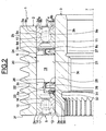
figure 1 est une demie-vue en coupe d'un dispositif de poulie débrayable selon un premier mode de réalisation; - la
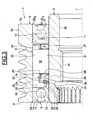
figure 2 est une demie-vue en coupe axiale selon II-II de lafigure 1 ; - la
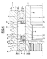
figure 3 est une demie-vue en coupe axiale d'un dispositif de poulie débrayable selon un deuxième mode de réalisation, et - la
figure 4 est une demie-vue en coupe axiale d'un dispositif de poulie débrayable selon un troisième mode de réalisation.
- the
figure 1 is a half-sectional view of a disengageable pulley device according to a first embodiment; - the
figure 2 is a half-view in axial section along II-II of thefigure 1 ; - the
figure 3 is a half-view in axial section of a disengageable pulley device according to a second embodiment, and - the
figure 4 is a half-view in axial section of a disengageable pulley device according to a third embodiment.
Comme on peut le voir sur les
La poulie 2, d'axe 7, présente une surface extérieure pourvue d'une zone rainurée 2a à rainures annulaires et une zone axiale 2b formée à une extrémité axiale de la zone rainurée 2a. La poulie 2 comprend un alésage cylindrique 2c s'étendant sur l'ensemble de la longueur de la poulie 2, à l'exception de chanfreins 2d et 2e disposés chacun à une extrémité axiale, et deux surfaces frontales radiales 2f et 2g.The
L'élément intérieur de transmission 3, qui se présente sous la forme d'un arbre creux, possède une surface extérieure axiale 3a cylindrique sur laquelle est prévu, à chacune des extrémités axiales, un chanfrein (non référencé). L'élément intérieur de transmission 3 présente également un alésage 3b dont une partie 3c comporte un filetage en vue de la fixation sur l'extrémité d'un arbre d'alternateur et de l'entraînement dudit arbre (non représenté).The
Le roulement 4, coaxial avec l'axe 7, comprend une bague intérieure 8, une bague extérieure 9, entre lesquelles sont logés une rangée d'éléments roulants 10 réalisés ici sous forme de billes, une cage 11 de maintien de l'espace circonférentiel des éléments roulants 10, et un joint d'étanchéité 12.The
La bague intérieure 8 comprend un alésage 8a de forme cylindrique, emmanché avec la surface extérieure 3a de l'élément intérieur de transmission 3, et délimité par deux surfaces latérales radiales 8b et 8c opposées, et une surface cylindrique extérieure 8d étagée à partir de laquelle est formée une gorge circulaire 8e présentant en section droite un profil interne concave apte à former un chemin de roulement pour les éléments roulants 10, ladite gorge étant orientée vers l'extérieur.The
La bague extérieure 9 comprend une surface cylindrique extérieure 9a emmanchée dans l'alésage 2c de la poulie 2 et délimitée par des surfaces frontales 9b et 9c, et un alésage 9d étagé de forme cylindrique à partir duquel est formée une gorge circulaire 9e présentant en section droite un profil interne concave apte à former un chemin de roulement pour les éléments roulants 10 orienté vers l'intérieur. L'alésage 9d comprend ici deux rainures annulaires (non référencées) symétriques entre elles par rapport à un plan passant par le centre des éléments roulants 10. A l'intérieur de la rainure annulaire située du côté extérieur du roulement 4 est monté le joint d'étanchéité 12 qui vient frotter contre la surface extérieure cylindrique 8d de la bague intérieure 8 pour former étanchéité. Le joint d'étanchéité 12 est disposé radialement entre les bagues intérieure et extérieure 8, 9, et monté axialement entre les éléments roulants 10 et les surfaces radiales 8b et 9b des bagues 8 et 9. Lesdites surfaces affleurent axialement avec la surface frontale radiale 2g de la poulie 2.The
De manière analogue, le roulement 5, coaxial avec l'axe 7, comprend une bague intérieure 13 emmanché avec la surface extérieure 3a de l'élément intérieur de transmission 3, une bague extérieure 14 emmanchée dans l'alésage 2c de la poulie 2, entre lesquelles sont logés une rangée d'éléments roulants 15 réalisés ici sous forme de billes, une cage 16 de maintien de l'espace circonférentiel des éléments roulants 15, et un joint d'étanchéité 17 métallique. Le roulement 5 est identique au roulement 4, et est disposé de façon symétrique par rapport à celui-ci en considérant un plan radial passant par le centre de la poulie 2. Le roulement 5 affleure ainsi axialement avec la surface frontale radiale 2f de la poulie 2.Similarly, the
Les roulements 4 et 5 sont donc disposés à chaque extrémité axiale de la poulie 2, la roue libre 6 étant montée axialement entre eux. La roue libre 6 bénéficie ainsi d'une protection contre l'intrusion des éléments étrangers par l'intermédiaire des roulements 4 et 5, et notamment des joints d'étanchéité 12 et 17.The
La roue libre 6 comprend une pluralité d'éléments de coincement ou cames 19 disposées entre deux chemins de glissement 20 et 21, de forme cylindrique de révolution. Les cames 19 sont de type « engageantes », c'est-à-dire ayant tendance, sous l'effet des forces centrifuges lors de la rotation de la roue libre, à basculer dans le sens favorisant leur blocage entre les deux chemins de glissement 20 et 21, en vue de faciliter un passage quasi instantané du fonctionnement en roue libre au fonctionnement en prise de couple.The
Le chemin de glissement 20 est formé par l'alésage 2c de la poulie 2. Le chemin de glissement 21 est formé par la surface extérieure axiale 3a de l'arbre 3.The sliding
En d'autres termes, la poulie 2 peut être fabriquée avec une surface intérieure de forme particulièrement simple entièrement axiale à l'exception des chanfreins 2d et 2e d'extrémité. La poulie 2 peut donc être obtenue à faible prix de revient. Cette surface intérieure constitue une portée extérieure pour les cames 19, ou de grand diamètre.In other words, the
Du côté opposé, le chemin de glissement 21 est formé sur la surface extérieure 3a de l'arbre 3. Le profil extérieur de révolution de l'arbre 3 possède le même diamètre sur toute sa longueur. La finition peut être effectuée en une seule opération sur une machine de rectification et permet d'obtenir en grande série et à faible coût le chemin de glissement 21 de petit diamètre, ou portée intérieure, pour les cames 19 de la roue libre 6.On the opposite side, the sliding
La roue libre 6 comprend également une cage 22 de forme générale annulaire pouvant être réalisée dans une matière métallique, notamment en acier, ou encore à partir d'une matière synthétique tel que du polyamide.The
La cage 22 comprend une portion axiale 23 et deux portions radiales 24, 25. La portion radiale 24 prolonge radialement vers l'extérieur une extrémité axiale de la portion 23 située au voisinage du roulement 4, tandis que la portion radiale 25 prolonge radialement vers l'intérieur une extrémité axiale de la portion 23 située au voisinage du roulement 5. Les extrémités libres des portions radiales 24 et 25 sont situées à proximité de l'alésage 2c de la poulie 2 et de la surface extérieure 3a de l'élément intérieur de transmission 3, respectivement. En d'autres termes, la portion radiale 24 reste à distance de l'alésage 2c, la portion radiale 25 restant quant à elle à distance de la surface extérieure 3a.The
La cage 22 comprend également une pluralité de fenêtres 26 ménagées dans la portion axiale 23 et formant un logement pour les cames 19. Les fenêtres 26 sont régulièrement espacées l'une par rapport à l'autre dans le sens circonférentiel. La cage 22 permet un maintien circonférentiel des cames 19 à espacement régulier.The
La roue libre 6 comporte en outre un ressort 27 qui est réalisé sous la forme d'une bande métallique annulaire enroulée sur elle-même et raccordée bout à bout ou avec recouvrement partiel. Le ressort 27 est monté à l'intérieur de la cage 22, et plus particulièrement disposé radialement entre la surface extérieure 3a de l'élément de transmission 3 et la portion axiale 23 de la cage 22. Le ressort 27 est situé axialement entre les portions radiales 24 et 25 de la cage 22.The
Le ressort 27 comporte également des alvéoles ou fenêtres 28 qui correspondent à celles de la cage 22 pour pouvoir monter les cames 19. Ainsi, les fenêtres 28 sont circonférentiellement régulièrement espacées.The
Le ressort 27 est encore pourvu d'au moins un élément de rappel 29 élastique par came 19 réalisé sous la forme d'une languette, et prévu pour appuyer sur une surface ménagée à cet effet sur la came 19 associée afin d'exercer un couple de basculement tendant à maintenir les cames 19 en contact avec les chemins de glissement 20 et 21. Dans une position statique, les éléments de rappel 29 exercent un effort dirigé vers la poulie 2.The
En variante, un élément de rappel individuel associé à chaque came exerce un effort tendant à maintenir un contact permanent avec les chemins de glissement 20 et 21. I1 est par exemple possible de monter pour chacune des cames 19 un ressort de rappel élastique disposé entre la came 19 et la cage 22.As a variant, an individual return element associated with each cam exerts a force tending to maintain permanent contact with the sliding
Pour relier par friction la cage 22 et l'élément intérieur 3 de transmission, la roue libre 6 comporte également un élément de friction 30 annulaire prévu entre la cage 22 et la surface extérieure 3a de l'élément intérieur 3. L'élément de friction 30 est ici rapporté sur la cage 22. Toutefois, en variante, un élément de friction 30 est monté sur la surface extérieure 3a de l'élément intérieur 3 de transmission.To frictionally connect the
L'élément de friction 30 annulaire comporte un corps de friction 31 et un anneau de serrage 32 élastique du corps entourant une portion du corps en contact de friction avec l'élément intérieur 3 de transmission.The annular friction member comprises a
Le corps de friction 31 annulaire est réalisé en matière synthétique, par exemple en élastomère. I1 est pourvu d'une portion radiale (non référencée) fixée à l'extrémité libre de la portion radiale 25 de la cage 22, d'une première portion oblique (non référencée) prolongeant vers l'intérieur la portion radiale en direction de l'élément de transmission 3 et des cames 19, et d'une seconde portion oblique (non référencée) prolongeant vers l'extérieur un bord de petit diamètre de la première portion oblique. Une surface intérieure de la zone de jonction des première et seconde portions obliques vient en contact de friction contre la surface extérieure 3a de l'élément de transmission 3. Le corps de friction 31 peut avantageusement être surmoulé directement sur la portion radiale 25 de la cage 22 de manière à obtenir un ensemble unitaire, et présente un coefficient de friction élevé de manière à pouvoir entraîner en rotation l'élément de transmission 3.The
L'anneau de serrage 32 élastique est réalisé en matière métallique. I1 est monté en appui contre une surface extérieure de ladite zone de jonction des première et seconde portions obliques. I1 forme un ressort et est apte à pré-contraindre radialement le corps de friction 31, sur la surface extérieure 3a de l'élément intérieur de transmission 3 afin de maintenir en contact ces deux éléments et de rattraper les usures.The
Le mode de fonctionnement de la roue libre 6 est le suivant. Lors d'un régime stabilisé ou lors d'une accélération de la poulie 2, les cames 19 ont tendance, sous l'effet des forces centrifuges et par contact avec les chemins de glissement 20 et 21, à basculer dans un premier sens qui permet d'obtenir par arc-boutement entre les deux chemins de glissement un blocage avec les deux chemins de glissement 20 et 21 de la poulie 2 et de l'élément intérieur 3 de transmission. La roue libre 6 fonctionne en prise de couple ou embrayée et transmet un couple d'entraînement entre la poulie 2 et l'élément intérieur 3.The operating mode of the
Au contraire, lors d'une décélération rapide de la poulie 2, les cames 19 ont tendance à basculer dans un second sens opposé au premier, ce qui provoque le déblocage ou décoincement des cames 19. La roue libre 6 ne transmet alors plus de couple et permet temporairement un déplacement relatif en rotation de la poulie 2 par rapport à l'élément de transmission 3 intérieur. La roue libre 6 assure ainsi un accouplement unidirectionnel entre la poulie 2 et l'élément de transmission 3.On the contrary, during a rapid deceleration of the
Dans cette position débrayée, les éléments de rappel 29 élastique disposés entre l'unique cage 22 et les cames 19 ont tendance à maintenir un contact glissant entre le chemin de glissement 20 de la poulie 2 parfaitement lubrifié et lesdites cames 19. Lors de l'état transitoire entre le passage de la position embrayée à la position débrayée, ou inversement, la demanderesse a déterminé que la disposition relative des éléments de rappel 29 élastique et de la cage 22 permet de maintenir efficacement le contact entre les cames 19 et les chemins de glissement 20, 21.In this disengaged position, the
Dans la position débrayée, l'élément de friction 30 annulaire prévu entre la cage 22 et le chemin 21 de glissement de l'élément intérieur 3 de transmission tend à entraîner en rotation par friction la roue libre 6 par l'intermédiaire de ladite cage à la même vitesse que l'élément intérieur 3 de transmission. Ainsi, l'élément intérieur 3 de transmission et la cage 22 sont solidaires en rotation et on supprime ou limite ainsi le glissement relatif entre le chemin 21 de glissement ménagé sur l'élément intérieur 3 de transmission et les cames 19. Les cames 19 et l'élément intérieur 3 de transmission sont en contact mais avec un glissement relatif faible ou nul.In the disengaged position, the annular friction element provided between the
Cet entraînement en rotation est effectif tant qu'un couple de traînée dû au frottement des cames 19 sur le chemin de glissement 20 de la poulie 2 est inférieur au couple de friction entre l'élément de friction 30 et la surface extérieure 3a de l'élément intérieur 3 de transmission. Dans ce cas, il existe alors un glissement avec contact entre les cames 19 et le chemin de glissement 21. Dans le cas d'une éventuelle usure du corps de friction 31 par frottement avec ladite surface extérieure 3a, l'anneau de serrage 32 élastique permet de déformer radialement vers l'intérieur la zone de jonction des portions obliques afin de maintenir un contact de friction entre l'élément 30 et l'élément intérieur 3 de transmission. En d'autres termes, l'anneau de serrage 32 permet d'obtenir un élément de friction à rattrapage d'usure.This rotational drive is effective as long as a drag torque due to the friction of the
Le mode de réalisation illustré sur la
La zone radialement élastique comprend ici une première portion axiale (non référencée) annulaire fixée sur la portion radiale 25 de la cage 22, qui est prolongée vers l'intérieur par une première portion oblique s'étendant vers l'intérieur en direction du ressort 27, elle-même prolongée à un bord de petit diamètre par une seconde portion oblique s'étendant vers l'intérieur en direction du roulement 5.The radially elastic zone here comprises a first annular (unreferenced) axial portion fixed on the
Le corps 36 forme ainsi une ligne brisée à angles alternativement rentrant et saillant offrant une grande élasticité radiale et permettant un rattrapage d'une éventuelle usure de fonctionnement de la lèvre 37. Ladite lèvre 37 est reliée à la seconde portion oblique du corps 36. La lèvre 37 s'étend axialement le long de la surface extérieure 3a de l'élément intérieur 3 de transmission et est en contact de friction contre ladite surface. Elle présente un coefficient de friction élevé de manière à pouvoir entraîner en rotation l'élément de transmission 3. La lèvre 37 est en contact de friction avec ladite surface extérieure 3a.The
Dans ce mode de réalisation, la cage 22 peut être réalisée dans une matière métallique, notamment en acier, ou encore à partir d'une matière synthétique tel que du polyamide. En variante, la cage 22 de logement et l'élément de friction 35 sont venus de matière et obtenus par moulage d'une matière synthétique tel que du polyamide, notamment du PA 4-6.In this embodiment, the
Dans une autre variante de réalisation, un élément de friction 35 est monté sur la surface extérieure 3a de l'élément intérieur 3 de transmission et vient en contact de friction avec la cage 22.In another variant embodiment, a
Le mode de réalisation illustré sur la
Dans une application sur une poulie d'entraînement d'un alternateur pour véhicule automobile, grâce à la roue libre, la poulie entraîne l'arbre central lorsque le moteur accélère ou est en régime sensiblement continu ou bien décélère très lentement. En cas de ralentissement brutal du moteur et donc de la poulie, l'axe central du dispositif de poulie débrayable peut continuer à tourner plus rapidement que la poulie proprement dite grâce à la roue libre, épargnant ainsi des contraintes excessives à la courroie d'entraînement. En outre, la roue libre permet un passage quasi instantané du fonctionnement en roue libre au fonctionnement en prise de couple, et présente une bonne fiabilité dans le temps.In an application on a drive pulley of an alternator for a motor vehicle, thanks to the freewheel, the pulley drives the central shaft when the engine accelerates or is in a substantially continuous mode or decelerates very slowly. In the event of a sudden slowing down of the engine and therefore of the pulley, the central axis of the disengageable pulley device can continue to rotate faster than the actual pulley thanks to the freewheel, thus sparing excessive stress on the drive belt. In addition, the freewheel allows an almost instantaneous transition from freewheel operation to torque-driven operation, and has good reliability over time.
Claims (12)
- Disengageable pulley device comprising a pulley (2) mounted on an inner transmission element (3), and a freewheel (6) provided with a plurality of lock-up elements (9) mounted between a sliding track (20) of the pulley and a sliding track (21) of the inner transmission element, the said freewheel being intended to provide a one-way coupling between the pulley (2) and the inner transmission element (3), where the diengageable pulley device is provided with a cage (22) for the lock-up elements, with at least one annular friction element (30; 35; 40) provided between the cage (22) and the sliding track (21) of the inner transmission element to use friction to connect the cage and the said inner element, and with at least one elastic return element (29) positioned between at least one lock-up element and the cage, the elastic return element (29) tending to keep the lock-up elements in contact with the sliding tracks (20, 21) when the freewheel is in the coupled position and in the uncoupled position.
- Device according to Claim 1, comprising a single cage (22) for the lock-up elements.
- Device according to Claim 1 or 2, in which, in an uncoupled position, the inner transmission element (3) tends to drive the freewheel (6) substantially at the same speed, via the friction element (30; 35; 40) and the cage (22).
- Device according to any one of the preceding claims, in which the annular friction element (30; 35; 40) is mounted on the cage (22).
- Device according to any one of the preceding claims, comprising at least one elastic return element (29) positioned between each lock-up element and the cage.
- Device according to any one of the preceding claims, in which the elastic return element (29) is positioned radially between the cage and the inner transmission element.
- Device according to any one of the preceding claims, in which the annular friction element (30; 35; 40) is positioned on a radial portion of the cage (22).
- Device according to any one of the preceding claims, in which the friction element (30; 35; 40) comprises a region that is elastic radially towards an exterior surface of the inner transmission element (3).
- Device according to any one of the preceding claims, in which the friction element (30) comprises a friction body (31) and a clamping ring (32) for the body in frictional contact.
- Device according to any one of Claims 1 to 8, in which the annular friction element (35) comprises a friction lip (37) supported by a radially elastic region.
- Device according to any one of Claims 1 to 8, in which the friction element (40) consists of a friction body (41).
- Alternator comprising a shaft and a disengageable pulley device according to any one of the preceding claims, mounted on the said shaft.
Applications Claiming Priority (1)
| Application Number | Priority Date | Filing Date | Title |
|---|---|---|---|
| FR0654082A FR2906858B1 (en) | 2006-10-04 | 2006-10-04 | DEBRAYABLE PULLEY DEVICE. |
Publications (2)
| Publication Number | Publication Date |
|---|---|
| EP1908980A1 EP1908980A1 (en) | 2008-04-09 |
| EP1908980B1 true EP1908980B1 (en) | 2011-08-03 |
Family
ID=37964011
Family Applications (1)
| Application Number | Title | Priority Date | Filing Date |
|---|---|---|---|
| EP07116412A Expired - Fee Related EP1908980B1 (en) | 2006-10-04 | 2007-09-14 | Disconnectable pulley device |
Country Status (5)
| Country | Link |
|---|---|
| US (1) | US20080090686A1 (en) |
| EP (1) | EP1908980B1 (en) |
| JP (1) | JP5389344B2 (en) |
| CN (1) | CN101178099B (en) |
| FR (1) | FR2906858B1 (en) |
Families Citing this family (8)
| Publication number | Priority date | Publication date | Assignee | Title |
|---|---|---|---|---|
| EP1947370A1 (en) * | 2005-10-14 | 2008-07-23 | JTEKT Corporation | Pulley apparatus and auto-tensioner |
| FR2902699B1 (en) | 2006-06-26 | 2010-10-22 | Skf Ab | SUSPENSION STOP DEVICE AND FORCE LEG. |
| FR2906587B1 (en) | 2006-10-03 | 2009-07-10 | Skf Ab | TENDERING ROLLER DEVICE. |
| FR2913081B1 (en) | 2007-02-27 | 2009-05-15 | Skf Ab | DEBRAYABLE PULLEY DEVICE |
| DE102008030017B4 (en) * | 2008-06-24 | 2016-07-21 | Schaeffler Technologies AG & Co. KG | Metal cages for sprag clutches |
| WO2011015181A1 (en) * | 2009-08-06 | 2011-02-10 | Schaeffler Technologies Gmbh & Co. Kg | Freewheel, in particular for a crank-cvt transmission |
| DE102013202699A1 (en) * | 2013-02-20 | 2014-08-21 | Schaeffler Technologies Gmbh & Co. Kg | Pulley arrangement for a belt drive for driving auxiliary units of a motor vehicle and method for driving a connected via a pulley assembly accessory of a motor vehicle |
| DE102019133200B3 (en) | 2019-12-05 | 2021-03-11 | Schaeffler Technologies AG & Co. KG | Roller freewheel unit for a vehicle, vehicle with a roller freewheel unit and use and method for assembling the roller freewheel unit |
Family Cites Families (106)
| Publication number | Priority date | Publication date | Assignee | Title |
|---|---|---|---|---|
| US1368068A (en) * | 1920-05-29 | 1921-02-08 | Stein Louis | Hose-coupling |
| CH89090A (en) * | 1934-02-12 | 1921-04-16 | Messerli Johann | Tool holder. |
| US2140975A (en) * | 1936-10-27 | 1938-12-20 | William T Welch | Clutch mechanism |
| US2576337A (en) * | 1947-01-25 | 1951-11-27 | Ford Motor Co | Overrunning sprag type clutch |
| US2630896A (en) * | 1951-08-02 | 1953-03-10 | Adiel Y Dodge | One-way clutch |
| US2940568A (en) * | 1957-03-25 | 1960-06-14 | Borg Warner | One-way clutch and drag spring |
| US3008362A (en) * | 1959-03-20 | 1961-11-14 | Babcock & Wilcox Co | Power operated stud tensioners |
| US3258962A (en) * | 1963-02-14 | 1966-07-05 | Asea Ab | Magneto-elastic force measuring device |
| US3365967A (en) * | 1965-06-07 | 1968-01-30 | Moogk Friedrich | Stepless variable v-belt driving gear with asymmetric v-belt |
| US3545581A (en) * | 1968-12-19 | 1970-12-08 | Borg Warner | Sprag assembly for one-way clutches |
| US3702649A (en) * | 1970-01-31 | 1972-11-14 | Ringspann Maurer Kg A | One-way clutch having tiltable sprags |
| US3743066A (en) * | 1972-07-05 | 1973-07-03 | Skf Cie Applic Mecanique | Free wheel drive |
| DE2361916C2 (en) * | 1973-12-13 | 1975-03-06 | Stieber Division Der Borg-Warner Gmbh, 6900 Heidelberg | Sprag overrunning clutch |
| FR2304829A1 (en) * | 1975-03-21 | 1976-10-15 | Ferodo Sa | RELEASE STOP |
| US3965565A (en) * | 1975-06-04 | 1976-06-29 | Kaneharu Fujii | Method of and apparatus for tightening high-strength steel bolts |
| US4020720A (en) * | 1975-06-04 | 1977-05-03 | Kaneharu Fujii | Apparatus for tightening high-strength steel bolts |
| US3997041A (en) * | 1975-09-19 | 1976-12-14 | Borg-Warner Corporation | One-way clutch |
| US4046238A (en) * | 1976-02-03 | 1977-09-06 | Mendoza Orozco Hector | Free-wheeling mechanism for bicycles |
| CH614960A5 (en) * | 1976-04-15 | 1979-12-28 | Ciba Geigy Ag | |
| US4319220A (en) * | 1976-08-31 | 1982-03-09 | Dennis G. Pappas | Alarm system for monitoring pressurized vehicular tires |
| DE2718602A1 (en) * | 1977-04-22 | 1978-10-26 | Kraftwerk Union Ag | DEVICE FOR TENSIONING SEVERAL SCREW BOLTS |
| DE2758841C2 (en) * | 1977-12-30 | 1986-09-04 | Stieber Division Der Borg-Warner Gmbh, 6900 Heidelberg | Sprag overrunning clutch |
| CH631013A5 (en) * | 1978-09-20 | 1982-07-15 | Schmid Roost J Sro Kugellagerw | MEASURING DEVICE. |
| US4505484A (en) * | 1980-03-12 | 1985-03-19 | Nippon Seiko Kabushiki Kaisha | Sealing device for a rolling bearing |
| JPS57161344A (en) * | 1981-03-27 | 1982-10-04 | Nippon Denso Co Ltd | Belt tension control device |
| DE3117162C2 (en) * | 1981-04-30 | 1983-02-17 | Skf Kugellagerfabriken Gmbh, 8720 Schweinfurt | "Process for the production of pairs of plastic-coated races for rolling bearings" |
| US4523742A (en) * | 1982-01-25 | 1985-06-18 | Gripper, Inc. | Apparatus for tensioning a stud and method of doing same |
| US4438901A (en) * | 1982-01-25 | 1984-03-27 | Gripper, Inc. | Apparatus for tensioning a stud and method of doing same |
| JPS58145522A (en) * | 1982-02-20 | 1983-08-30 | Honda Motor Co Ltd | Motive power transmission device for vehicle |
| JPS58163832A (en) * | 1982-03-24 | 1983-09-28 | Tsubakimoto Moorusu:Kk | One-way clutch |
| JPS58151743U (en) * | 1982-04-06 | 1983-10-11 | アイシン精機株式会社 | Piston for cylinder device |
| US4601374A (en) * | 1982-04-22 | 1986-07-22 | Federal-Mogul Corporation | Hydraulic clutch piston and seal |
| US4497523A (en) * | 1983-02-28 | 1985-02-05 | General Motors Corporation | Modular suspension strut bearing |
| FR2544429B1 (en) * | 1983-04-15 | 1985-08-02 | Valeo | METHOD FOR MOUNTING A RELEASE STOPPER, AND CORRESPONDING RELEASE STOPPER, PARTICULARLY FOR A MOTOR VEHICLE |
| DE3445541A1 (en) * | 1984-01-04 | 1985-07-11 | Skandiafabriken AB, Mullsjö | LIQUID LEVEL INDICATOR |
| US4708036A (en) * | 1984-02-07 | 1987-11-24 | Haskel, Inc. | Stud tensioning apparatus |
| US4541744A (en) * | 1984-11-15 | 1985-09-17 | General Motors Coporation | Unitized bearing assembly with moldable race members and labryinth seal |
| US5033013A (en) * | 1985-04-22 | 1991-07-16 | Yamasa Tokei Meter Co., Ltd. | Method and apparatus for measuring the amount of exercise |
| US4699530A (en) * | 1985-06-28 | 1987-10-13 | Oiless Industry Co., Ltd. | Thrust ball bearing unit |
| US4602875A (en) * | 1985-11-18 | 1986-07-29 | General Motors Corporation | Combined bearing, rotatable member and shield assembly |
| US4756395A (en) * | 1985-12-03 | 1988-07-12 | Dana Corporation | Overrunning clutch with controlled sprag action |
| GB2194638B (en) * | 1986-03-27 | 1990-01-10 | Protos Precision Systems Ltd | Shapemeter |
| JPH0633223Y2 (en) * | 1986-05-16 | 1994-08-31 | 本田技研工業株式会社 | One way clutch |
| FR2599794B1 (en) * | 1986-06-10 | 1991-06-07 | Roulements Soc Nouvelle | BEARING OR BEARING WITH INFORMATION SENSOR |
| JPH0313625Y2 (en) * | 1986-12-10 | 1991-03-28 | ||
| EP0272544B1 (en) * | 1986-12-22 | 1990-09-26 | Siemens Aktiengesellschaft | Angular-position encoder with a photo-electrically palpable encoder disc and double axle bearing |
| FR2609126B1 (en) * | 1986-12-29 | 1989-10-27 | Valeo | RELEASE STOP, ESPECIALLY FOR A MOTOR VEHICLE |
| FR2611009B1 (en) * | 1987-02-17 | 1989-05-19 | Valeo | RELEASE STOP, ESPECIALLY FOR A MOTOR VEHICLE |
| JPS63246516A (en) * | 1987-04-02 | 1988-10-13 | Nippon Seiko Kk | Clutch release bearing device |
| US4722617A (en) * | 1987-07-17 | 1988-02-02 | The Torrington Company | Ball bearing assembly |
| DE3729632A1 (en) * | 1987-09-04 | 1989-03-16 | Schaeffler Waelzlager Kg | FREE CLUTCH WITH CLAMP BODIES |
| US4815867A (en) * | 1987-09-23 | 1989-03-28 | Federal-Mogul Corporation | Side assembled clip for self-aligning bearing |
| DE3742030C2 (en) * | 1987-12-11 | 1997-06-19 | Skf Gmbh | Swivel bearing for clamping devices |
| JPH01188726A (en) * | 1988-01-21 | 1989-07-28 | Nsk Warner Kk | Holder for one-way clutch |
| DE8810259U1 (en) * | 1988-08-12 | 1988-11-17 | Messer Griesheim Gmbh, 6000 Frankfurt, De | |
| GB8823474D0 (en) * | 1988-10-06 | 1988-11-16 | Hedley Purvis Ltd | Improved hydraulic tensioner |
| FR2640706B1 (en) * | 1988-12-20 | 1991-02-01 | Roulements Soc Nouvelle | INFORMATION SENSOR BEARING |
| US5008647A (en) * | 1989-02-06 | 1991-04-16 | Orleander S.A. | Wireless bicycle wheel monitor system |
| US4915512A (en) * | 1989-03-24 | 1990-04-10 | The Torrington Company | Thrust bearing with a magnetic field sensor |
| US5017741A (en) * | 1989-03-29 | 1991-05-21 | Hamilton Standard Controls, Inc. | Rotary digital contact encoder substrate |
| US4970945A (en) * | 1989-04-28 | 1990-11-20 | General Motors Corporation | Actuating piston assembly, and seal therefor, for torque transmitting systems |
| US5018384A (en) * | 1989-07-21 | 1991-05-28 | Nippon Seiko Kabushiki Kaisha | Rotational speed detector |
| IT1240481B (en) * | 1990-07-04 | 1993-12-17 | Skf Ind Spa | DEVICE SUITABLE FOR ALLOWING THE ROTATION SPEED TO BE DETECTED BETWEEN TWO BODIES IN RELATIVE ROTATION SUCH AS THE SUPPORT BODIES OF A WHEEL OF A VEHICLE. |
| DE4015028A1 (en) * | 1990-05-10 | 1992-01-16 | Skf Gmbh | PRE-ADJUSTABLE CLAMPING DEVICE |
| US5051693A (en) * | 1990-09-07 | 1991-09-24 | The Torrington Company | Bearing seat encoder mount for rotational parameter sensor apparatus |
| DE4036024C1 (en) * | 1990-11-13 | 1992-02-27 | Heidelberger Druckmaschinen Ag, 6900 Heidelberg, De | |
| IT1256785B (en) * | 1992-01-28 | 1995-12-15 | Skf Ind Spa | SEALING COMPLEX WITH A SENSOR DEVICE ON BOARD, FOR A ROLLING BEARING. |
| DE4233896C2 (en) * | 1992-10-08 | 1995-06-08 | Bosch Gmbh Robert | piston |
| FR2700588B1 (en) * | 1993-01-19 | 1995-02-17 | Roulements Soc Nouvelle | Mounting device with integrated encoder seal. |
| FR2712048B1 (en) * | 1993-11-04 | 1995-12-15 | Roulements Soc Nouvelle | Seal for information sensor bearings and bearing fitted in this way. |
| DE4408873C2 (en) * | 1994-03-16 | 1999-02-11 | Westfalia Nukleartechnik Gmbh | Screw tensioning device, in particular for screwed covers, especially in the case of reactor pressure vessels |
| US5454585A (en) * | 1994-08-08 | 1995-10-03 | General Motors Corporation | Strut assembly with bearing axis alignment |
| JPH08140308A (en) * | 1994-11-10 | 1996-05-31 | Mitsubishi Electric Corp | Charging generator for vehicle |
| DE19503469C1 (en) * | 1995-02-03 | 1996-05-30 | Freudenberg Carl Fa | Seal for relatively rotating components cooperating with rotation sensor |
| FR2730534B1 (en) * | 1995-02-09 | 1997-04-04 | Valeo | HYDRAULICALLY CONTROLLED CLUTCH STOPPER FOR A MOTOR VEHICLE DIAPHRAGM CLUTCH |
| FR2730566B1 (en) * | 1995-02-09 | 1997-06-13 | Skf France | ENCODER DEVICE FOR ROTATION SPEED SENSOR AND BEARING PROVIDED WITH SUCH A DEVICE |
| DE19506144C1 (en) * | 1995-02-22 | 1996-05-30 | Rasmussen Gmbh | Device for clamping a hose end section pushed onto a pipe end section |
| US5592401A (en) * | 1995-02-28 | 1997-01-07 | Virtual Technologies, Inc. | Accurate, rapid, reliable position sensing using multiple sensing technologies |
| JPH08292111A (en) * | 1995-04-24 | 1996-11-05 | Mitsubishi Electric Corp | Belt-tension measuring apparatus |
| US5598913A (en) * | 1995-06-07 | 1997-02-04 | Ntn Corporation | One-way over-running clutch pulley |
| US5657544A (en) * | 1995-09-26 | 1997-08-19 | Ntn Corporation | Device for detecting the angle of rotation |
| US6011491A (en) * | 1995-10-10 | 2000-01-04 | Goetzl; Brent A. | Speedometer for in-line skates |
| US5721539A (en) * | 1995-10-10 | 1998-02-24 | Goetzl; Brent A. | Speedometer for in-line skates |
| US5845230A (en) * | 1996-01-30 | 1998-12-01 | Skf Condition Monitoring | Apparatus and method for the remote monitoring of machine condition |
| DE19614385A1 (en) * | 1996-03-04 | 1997-09-11 | Schaeffler Waelzlager Kg | Seal for an annular piston of a hydraulic clutch release device |
| WO1997033105A1 (en) * | 1996-03-08 | 1997-09-12 | Koyo Seiko Co., Ltd. | Variable diameter pulley |
| US5780731A (en) * | 1996-04-11 | 1998-07-14 | Denso Corporation | Method for judging the locked state of auxiliaries for automobiles |
| US6025737A (en) * | 1996-11-27 | 2000-02-15 | Altera Corporation | Circuitry for a low internal voltage integrated circuit |
| FR2754903B1 (en) * | 1996-10-23 | 1998-12-04 | Skf France | ENCODER DEVICE FOR ROTATION SPEED SENSOR AND BEARING PROVIDED WITH SUCH A DEVICE |
| DE19716218C2 (en) * | 1997-04-18 | 2001-08-30 | Schaeffler Waelzlager Ohg | Clutch release bearing |
| ES2205483T3 (en) * | 1997-05-07 | 2004-05-01 | Litens Automotive Partnership | SERPENTIN MOTOR SYSTEM WITH FREEWHEEL ALTERNATOR CLEANER. |
| DE69816755T2 (en) * | 1997-05-29 | 2004-06-03 | Ams International Ag | MAGNETIC ENCODER |
| JPH11117955A (en) * | 1997-10-13 | 1999-04-27 | Nsk Warner Kk | One-way clutch |
| DE29720776U1 (en) * | 1997-11-22 | 1998-01-15 | Skf Gmbh | Fastening device for belt rolls |
| FR2772920B1 (en) * | 1997-12-18 | 2000-02-04 | Skf France | IN-LINE SKATE WHEEL MOUNTING WITH ROTATION SPEED DETECTION DEVICE |
| JP4051114B2 (en) * | 1997-12-22 | 2008-02-20 | Nskワーナー株式会社 | Sprag type one-way clutch |
| US6013007A (en) * | 1998-03-26 | 2000-01-11 | Liquid Spark, Llc | Athlete's GPS-based performance monitor |
| FR2779096B1 (en) * | 1998-05-28 | 2000-12-15 | Skf France | SUSPENSION STOP DEVICE |
| US6196552B1 (en) * | 1998-06-08 | 2001-03-06 | Automotive Products (Usa), Inc. | Seal assembly for annular hydraulic cylinder |
| US6155543A (en) * | 1999-01-27 | 2000-12-05 | Daimlerchrysler Corporation | Spring seat assembly for an automotive vehicle |
| JP2000297860A (en) * | 1999-02-12 | 2000-10-24 | Nsk Ltd | Roller clutch-included type pulley device for alternator |
| US6160480A (en) * | 1999-09-24 | 2000-12-12 | Su-Yueh; Hsien Huang | Wireless inline-skate and skate board pulse watch with speed and heart rate monitoring |
| KR100799792B1 (en) * | 2000-03-28 | 2008-01-31 | 닛뽄 세이꼬 가부시기가이샤 | Rotation transmitting device incorporating one-way clutch therein |
| US6892868B2 (en) * | 2001-07-05 | 2005-05-17 | Koyo Seiko Co., Ltd. | One-way clutch |
| FR2856759B1 (en) | 2003-06-30 | 2006-07-14 | Skf France | FREE WHEEL DEVICE AND CAGE. |
| JP2005282856A (en) | 2004-03-02 | 2005-10-13 | Ntn Corp | One-way clutch and bearing compound one-way clutch |
-
2006
- 2006-10-04 FR FR0654082A patent/FR2906858B1/en not_active Expired - Fee Related
-
2007
- 2007-09-14 EP EP07116412A patent/EP1908980B1/en not_active Expired - Fee Related
- 2007-10-02 US US11/866,299 patent/US20080090686A1/en not_active Abandoned
- 2007-10-03 JP JP2007259914A patent/JP5389344B2/en not_active Expired - Fee Related
- 2007-10-08 CN CN2007101944689A patent/CN101178099B/en not_active Expired - Fee Related
Also Published As
| Publication number | Publication date |
|---|---|
| CN101178099A (en) | 2008-05-14 |
| FR2906858A1 (en) | 2008-04-11 |
| EP1908980A1 (en) | 2008-04-09 |
| JP2008089182A (en) | 2008-04-17 |
| FR2906858B1 (en) | 2008-12-05 |
| US20080090686A1 (en) | 2008-04-17 |
| CN101178099B (en) | 2011-12-07 |
| JP5389344B2 (en) | 2014-01-15 |
Similar Documents
| Publication | Publication Date | Title |
|---|---|---|
| EP1908980B1 (en) | Disconnectable pulley device | |
| FR2914381A1 (en) | DEBRAYABLE PULLEY DEVICE. | |
| FR2913081A1 (en) | DEBRAYABLE PULLEY DEVICE | |
| EP1651878B1 (en) | Freewheel bearing device with torque limiter | |
| EP1061278A1 (en) | Fastening device for a roller and roller comprising such a device | |
| FR2932863A1 (en) | PULLEY DEVICE FOR TENDER ROLLER OR ROLLER. | |
| FR2981715A1 (en) | PENDULUM OSCILLATOR TYPE DAMPING SYSTEM WITH IMPROVED GUIDE DEVICE | |
| FR2954437A1 (en) | PULLEY DEVICE FOR TENDER ROLLER OR ROLLER. | |
| FR2922605A1 (en) | DEBRAYABLE MODULE FOR A SYSTEM FOR TRANSMITTING A STARTING TORQUE TO AN INTERNAL COMBUSTION ENGINE | |
| FR2906329A1 (en) | Motor`s starting torque transmitting device for automobile, has leaf springs acquiring rollers towards clutched position, where each spring is made of leaf, which is extended from retainer`s body and provides specific elasticity | |
| FR3006711A1 (en) | WATER PUMP DRIVE SYSTEM AND MOUNTING METHOD | |
| FR2858377A1 (en) | FREE WHEEL DEVICE | |
| FR3086027A1 (en) | PULLEY DEVICE FOR TENSIONER OR ROLLER | |
| FR2835580A1 (en) | Ball bearing for electric motor etc. with outer race fitting within cylindrical seat | |
| FR2915778A1 (en) | BEARING BEARING DEVICE FOR STEERING COLUMN | |
| FR2936032A1 (en) | BEARING, ITS USE AND MOTOR VEHICLE EQUIPPED WITH SUCH A BEARING. | |
| EP1639267B9 (en) | Device and free wheel housing | |
| EP1900958B1 (en) | Disconnectable pulley device. | |
| FR2933460A1 (en) | DEBRAYABLE PULLEY DEVICE | |
| FR2939855A1 (en) | FREE WHEEL FOR DEBRAYABLE PULLEY DEVICE | |
| FR2938033A1 (en) | Switchable belt pulley device for installation on shaft of generator in motor vehicle, has cage including centering region that cooperates with slideway of belt pulley by direct or indirect frictional contact | |
| EP1500838B1 (en) | Freewheel device, pulley and alternator with a freewheel | |
| FR2866085A1 (en) | Axial stopper device for inertia wheel, has axial stop including outer and inner rings with constant thicknesses and set of rolling units and cage disposed in space defined between outer and inner rings | |
| FR2886693A1 (en) | ANTI-ROTATION DEVICE FOR ROLLING BEARING, AND BEARING AND MACHINE THEREFOR | |
| FR2816017A1 (en) | MAINTAINING CAGE OF PUNCHING ELEMENTS FOR FREE WHEEL DEVICE AND FREE WHEEL DEVICE |
Legal Events
| Date | Code | Title | Description |
|---|---|---|---|
| PUAI | Public reference made under article 153(3) epc to a published international application that has entered the european phase |
Free format text: ORIGINAL CODE: 0009012 |
|
| AK | Designated contracting states |
Kind code of ref document: A1 Designated state(s): AT BE BG CH CY CZ DE DK EE ES FI FR GB GR HU IE IS IT LI LT LU LV MC MT NL PL PT RO SE SI SK TR |
|
| AX | Request for extension of the european patent |
Extension state: AL BA HR MK RS |
|
| RIN1 | Information on inventor provided before grant (corrected) |
Inventor name: GARDELLE, JEAN-LUC Inventor name: ARNAULT, BENOIT Inventor name: CLAUDE, FRANCIS |
|
| 17P | Request for examination filed |
Effective date: 20080728 |
|
| 17Q | First examination report despatched |
Effective date: 20080916 |
|
| AKX | Designation fees paid |
Designated state(s): DE FR IT |
|
| R17C | First examination report despatched (corrected) |
Effective date: 20090520 |
|
| GRAC | Information related to communication of intention to grant a patent modified |
Free format text: ORIGINAL CODE: EPIDOSCIGR1 |
|
| GRAP | Despatch of communication of intention to grant a patent |
Free format text: ORIGINAL CODE: EPIDOSNIGR1 |
|
| GRAS | Grant fee paid |
Free format text: ORIGINAL CODE: EPIDOSNIGR3 |
|
| GRAA | (expected) grant |
Free format text: ORIGINAL CODE: 0009210 |
|
| AK | Designated contracting states |
Kind code of ref document: B1 Designated state(s): DE FR IT |
|
| REG | Reference to a national code |
Ref country code: DE Ref legal event code: R096 Ref document number: 602007016230 Country of ref document: DE Effective date: 20111006 |
|
| PG25 | Lapsed in a contracting state [announced via postgrant information from national office to epo] |
Ref country code: IT Free format text: LAPSE BECAUSE OF FAILURE TO SUBMIT A TRANSLATION OF THE DESCRIPTION OR TO PAY THE FEE WITHIN THE PRESCRIBED TIME-LIMIT Effective date: 20110803 |
|
| PLBE | No opposition filed within time limit |
Free format text: ORIGINAL CODE: 0009261 |
|
| STAA | Information on the status of an ep patent application or granted ep patent |
Free format text: STATUS: NO OPPOSITION FILED WITHIN TIME LIMIT |
|
| 26N | No opposition filed |
Effective date: 20120504 |
|
| REG | Reference to a national code |
Ref country code: DE Ref legal event code: R119 Ref document number: 602007016230 Country of ref document: DE Effective date: 20120403 |
|
| PG25 | Lapsed in a contracting state [announced via postgrant information from national office to epo] |
Ref country code: DE Free format text: LAPSE BECAUSE OF NON-PAYMENT OF DUE FEES Effective date: 20120403 |
|
| REG | Reference to a national code |
Ref country code: FR Ref legal event code: PLFP Year of fee payment: 9 |
|
| PGFP | Annual fee paid to national office [announced via postgrant information from national office to epo] |
Ref country code: FR Payment date: 20150928 Year of fee payment: 9 |
|
| REG | Reference to a national code |
Ref country code: FR Ref legal event code: ST Effective date: 20170531 |
|
| PG25 | Lapsed in a contracting state [announced via postgrant information from national office to epo] |
Ref country code: FR Free format text: LAPSE BECAUSE OF NON-PAYMENT OF DUE FEES Effective date: 20160930 |