EP1651878B1 - Freewheel bearing device with torque limiter - Google Patents
Freewheel bearing device with torque limiter Download PDFInfo
- Publication number
- EP1651878B1 EP1651878B1 EP04767457A EP04767457A EP1651878B1 EP 1651878 B1 EP1651878 B1 EP 1651878B1 EP 04767457 A EP04767457 A EP 04767457A EP 04767457 A EP04767457 A EP 04767457A EP 1651878 B1 EP1651878 B1 EP 1651878B1
- Authority
- EP
- European Patent Office
- Prior art keywords
- friction
- torque limiter
- ring
- limiter member
- torque
- Prior art date
- Legal status (The legal status is an assumption and is not a legal conclusion. Google has not performed a legal analysis and makes no representation as to the accuracy of the status listed.)
- Not-in-force
Links
Images


Classifications
-
- F—MECHANICAL ENGINEERING; LIGHTING; HEATING; WEAPONS; BLASTING
- F16—ENGINEERING ELEMENTS AND UNITS; GENERAL MEASURES FOR PRODUCING AND MAINTAINING EFFECTIVE FUNCTIONING OF MACHINES OR INSTALLATIONS; THERMAL INSULATION IN GENERAL
- F16D—COUPLINGS FOR TRANSMITTING ROTATION; CLUTCHES; BRAKES
- F16D43/00—Automatic clutches
- F16D43/02—Automatic clutches actuated entirely mechanically
- F16D43/20—Automatic clutches actuated entirely mechanically controlled by torque, e.g. overload-release clutches, slip-clutches with means by which torque varies the clutching pressure
- F16D43/21—Automatic clutches actuated entirely mechanically controlled by torque, e.g. overload-release clutches, slip-clutches with means by which torque varies the clutching pressure with friction members
- F16D43/211—Automatic clutches actuated entirely mechanically controlled by torque, e.g. overload-release clutches, slip-clutches with means by which torque varies the clutching pressure with friction members with radially applied torque-limiting friction surfaces
-
- F—MECHANICAL ENGINEERING; LIGHTING; HEATING; WEAPONS; BLASTING
- F16—ENGINEERING ELEMENTS AND UNITS; GENERAL MEASURES FOR PRODUCING AND MAINTAINING EFFECTIVE FUNCTIONING OF MACHINES OR INSTALLATIONS; THERMAL INSULATION IN GENERAL
- F16D—COUPLINGS FOR TRANSMITTING ROTATION; CLUTCHES; BRAKES
- F16D41/00—Freewheels or freewheel clutches
- F16D41/06—Freewheels or freewheel clutches with intermediate wedging coupling members between an inner and an outer surface
- F16D41/069—Freewheels or freewheel clutches with intermediate wedging coupling members between an inner and an outer surface the intermediate members wedging by pivoting or rocking, e.g. sprags
- F16D41/07—Freewheels or freewheel clutches with intermediate wedging coupling members between an inner and an outer surface the intermediate members wedging by pivoting or rocking, e.g. sprags between two cylindrical surfaces
-
- F—MECHANICAL ENGINEERING; LIGHTING; HEATING; WEAPONS; BLASTING
- F16—ENGINEERING ELEMENTS AND UNITS; GENERAL MEASURES FOR PRODUCING AND MAINTAINING EFFECTIVE FUNCTIONING OF MACHINES OR INSTALLATIONS; THERMAL INSULATION IN GENERAL
- F16D—COUPLINGS FOR TRANSMITTING ROTATION; CLUTCHES; BRAKES
- F16D41/00—Freewheels or freewheel clutches
- F16D41/20—Freewheels or freewheel clutches with expandable or contractable clamping ring or band
- F16D41/206—Freewheels or freewheel clutches with expandable or contractable clamping ring or band having axially adjacent coils, e.g. helical wrap-springs
-
- F—MECHANICAL ENGINEERING; LIGHTING; HEATING; WEAPONS; BLASTING
- F16—ENGINEERING ELEMENTS AND UNITS; GENERAL MEASURES FOR PRODUCING AND MAINTAINING EFFECTIVE FUNCTIONING OF MACHINES OR INSTALLATIONS; THERMAL INSULATION IN GENERAL
- F16D—COUPLINGS FOR TRANSMITTING ROTATION; CLUTCHES; BRAKES
- F16D7/00—Slip couplings, e.g. slipping on overload, for absorbing shock
- F16D7/02—Slip couplings, e.g. slipping on overload, for absorbing shock of the friction type
- F16D7/021—Slip couplings, e.g. slipping on overload, for absorbing shock of the friction type with radially applied torque-limiting friction surfaces
-
- F—MECHANICAL ENGINEERING; LIGHTING; HEATING; WEAPONS; BLASTING
- F16—ENGINEERING ELEMENTS AND UNITS; GENERAL MEASURES FOR PRODUCING AND MAINTAINING EFFECTIVE FUNCTIONING OF MACHINES OR INSTALLATIONS; THERMAL INSULATION IN GENERAL
- F16C—SHAFTS; FLEXIBLE SHAFTS; ELEMENTS OR CRANKSHAFT MECHANISMS; ROTARY BODIES OTHER THAN GEARING ELEMENTS; BEARINGS
- F16C19/00—Bearings with rolling contact, for exclusively rotary movement
- F16C19/02—Bearings with rolling contact, for exclusively rotary movement with bearing balls essentially of the same size in one or more circular rows
- F16C19/04—Bearings with rolling contact, for exclusively rotary movement with bearing balls essentially of the same size in one or more circular rows for radial load mainly
- F16C19/06—Bearings with rolling contact, for exclusively rotary movement with bearing balls essentially of the same size in one or more circular rows for radial load mainly with a single row or balls
-
- F—MECHANICAL ENGINEERING; LIGHTING; HEATING; WEAPONS; BLASTING
- F16—ENGINEERING ELEMENTS AND UNITS; GENERAL MEASURES FOR PRODUCING AND MAINTAINING EFFECTIVE FUNCTIONING OF MACHINES OR INSTALLATIONS; THERMAL INSULATION IN GENERAL
- F16C—SHAFTS; FLEXIBLE SHAFTS; ELEMENTS OR CRANKSHAFT MECHANISMS; ROTARY BODIES OTHER THAN GEARING ELEMENTS; BEARINGS
- F16C41/00—Other accessories, e.g. devices integrated in the bearing not relating to the bearing function as such
- F16C41/001—Integrated brakes or clutches for stopping or coupling the relatively movable parts
Definitions
- the present invention relates to the field of bearings comprising a unidirectional clutch or freewheel, generally interposed between an inner element and an outer element.
- the freewheel is used to transmit a torque in one direction and to allow relative rotation in the other direction.
- a bearing may also be interposed between the inner member and the outer member to support radial loads and possibly axial.
- the document FR A 2,726,059 describes a device of this kind.
- the invention proposes limiting the torque transmitted by a freewheel in a simple and compact manner.
- the invention proposes a torque limiter freewheel device which is easy to transport and handle and to integrate into a mechanical assembly.
- the freewheel device is of the type comprising an outer element, an inner element disposed in the outer element, and a freewheel provided with at least one wedging element, disposed between the inner element and the outer element to leave free a rotational movement in one direction between the outer member and the inner member and for transmitting torque in the other direction between the outer member and the inner member.
- the free wheel comprises a ring provided with a cylindrical inner surface and a cylindrical outer surface, substantially aligned on a radial plane perpendicular to the axis of rotation of the device, and a torque limiting member adapted to limit the torque transmitted by the free wheel, the torque limiting member being disposed radially between said ring and the outer member or the inner member in contact with said ring and said element.
- a sliding track may be formed on the cylindrical inner surface or the cylindrical outer surface, the torque limiting member being disposed in contact with the cylindrical outer surface or the cylindrical inner surface respectively.
- the free wheel and the torque limiting member are thus associated in a compact manner.
- the invention can use any type of known freewheel cams, roller, spring, or ratchet.
- the torque limiting member is mounted in series with the freewheel to limit the torque transmitted by the unidirectional engagement member in the torque transmission position.
- the torque limiting member comprises at least one friction element.
- the friction element may comprise a radial friction surface.
- the friction element may comprise an axial friction surface delimited by two radial planes.
- the device includes a bearing allowing the outer member to rotate relative to the inner member.
- the bearing is a rolling bearing.
- Running tracks for rolling elements of said bearing are provided in the inner and outer elements.
- the raceways are formed in inner and outer rings secured to the inner and outer elements.
- the torque limiting member is disposed on an outer surface of the freewheel.
- the torque limiting member is disposed in a bore of the freewheel.
- the torque limiting member comprises an open elastic ring provided with an outer friction surface and an inner friction surface.
- the ring may be made of sheet steel and may have a U-section provided with two axial wings.
- the torque limiting member comprises a plurality of resilient friction tabs.
- the torque limiting member comprises a resilient ring of synthetic material provided with an outer or inner friction surface and an inner or outer fixing surface respectively.
- the torque limiting member comprises at least one friction ring and an elastic washer for axially pressing the friction ring on a friction surface.
- the torque limiting member may comprise two friction rings between which is mounted said elastic washer.
- the friction rings may have radial friction surfaces.
- the torque limiting member comprises an open ring-shaped body.
- the ring of the freewheel and the body of the torque limiting member may be constituted by a single element whose outer surface is in contact with the outer element with friction in the case of angular rotation, and whose inner surface cooperates with the wedging element, or whose inner surface is in contact with the inner element with friction in case of angular rotation, and whose outer surface cooperates with the wedging element.
- the torque limiting member further comprises a resilient biasing member of said body.
- the elastic element may be a ring of the circlip type.
- the freewheel comprises a spring provided with an integral end of the torque limiting member and turns in frictional contact with the inner or outer element.
- the locking elements of the freewheel are cams, rollers or pawls.
- the torque limiting member comprises a friction element and a biasing element of the friction element against said ring and / or the outer element or the inner element.
- the friction element can be prestressed between said ring and the outer element, between said ring and the inner element, between two integral surfaces of the outer element, or between two integral surfaces of the outer element. interior element.
- the prestressing element is advantageously a separate part of the friction element.
- the torque limiting member is prestressed between two separate parts in opposite directions. More particularly, the torque limiting member may be preloaded radially outwardly against the outer member and radially inwardly against said ring, radially outwardly against said ring and radially inwardly against the ring. inner member, or axially against two opposed surfaces integral with the outer member or the inner member.
- freewheel here means a device for transmitting a torque in one direction and relative rotation in the other direction, possibly with negligible residual drag torque under normal operating conditions, between an input element and an element. output of the device.
- the invention limits the size of the device which is in the form of a pre-assembled compact cartridge relatively well protected against the external elements.
- the duration of The life of the moving parts upstream and downstream of the freewheel is lengthened by the clipping of torque peaks, resulting in a saving in operation and a reduction in the risk of breakage.
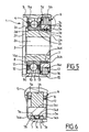
- the freewheel device As can be seen on the Figures 1 to 4 , the freewheel device, referenced 1 as a whole; comprises a tubular sleeve 2 of axis 3, a rolling bearing 4 mounted on the sleeve 2, an outer member 5 mounted on the bearing 4, a free wheel 6 mounted on the sleeve 2 and a friction element 7 mounted between the outer member 5 and freewheel 6.
- the sleeve 2 comprises a bore 2a, a front radial surface 2b, a cylindrical outer surface 2c extending over most of its length from the radial end surface 2b, a radial surface 2d extending towards the outside from the end of the cylindrical outer surface 2c, an axial surface 2e of short length extending from the free end of the radial portion 2d, axially opposite the radial end surface 2b , and a radial end surface 2f opposite to the radial end surface 2b.
- the bearing 4 may be of standard type, low cost of manufacture and comprises a solid inner ring 8 provided with a bore mounted, for example by fitting, on the outer cylindrical surface 2c of the sleeve 2, and in contact with the radial portion 2d, a massive outer ring 9, a row of elements 10, here balls, arranged between a raceway of the inner ring 8 and a raceway of the outer ring 9, a cage 11 for maintaining the circumferential spacing of the rolling elements 10 and seals 12 and 13 integral with the outer ring 9 and rubbing on a cylindrical surface of the inner ring 8, arranged on one side and the other of the row of rolling elements 10 to prevent the intrusion of foreign elements near the rolling elements 10 and to keep a lubricating product such as grease inside the bearing and near the rolling elements 10.
- the outer ring 9 is provided with an outer cylindrical surface 9a, coaxial with the outer cylindrical surface 2c of the sleeve 2.
- the outer element 5 comprises a central bore 5a mounted, for example by fitting, on the outer cylindrical surface 9a of the outer ring 9.
- the rolling bearing 4 thus ensures the freedom of rotation of the outer member 5 relative to the sleeve 2, and the resumption of radial efforts.
- the outer element 5 further comprises a bore 5b, of diameter very slightly greater than the central bore 5a, and disposed at the axial end of the outer element 5 located opposite the support 4.
- the bearing 4 and the outer element 5 are asymmetrical with respect to a radial plane passing through the center of the rolling elements 10.
- An annular radial surface 5c is formed between the bores 5a and 5b.
- the freewheel 6, mounted adjacent to the rolling bearing 4, comprises an outer ring 14, for example of solid type, whose bore forms a sliding track 14c, a row of wedging elements 15, here cams, a cage 16 provided with windows in which are arranged the wedging elements 15 in the form of cams and a spring 17 of return of the wedging elements 15 maintaining said wedging elements in permanent contact with the tracks.
- the wedging elements 15 are arranged radially between the outer cylindrical surface 2c of the sleeve 2 and the track 14c of the outer ring 14 axially between the rolling bearing 4 and the radial end surface 2b of the sleeve 2,
- the outer ring 14 comprises two circular ribs 14a, 14b, directed radially outward.
- the ribs 14a and 14b are disposed axially at the ends of the outer ring 14 while being aligned with the radial end surfaces of the outer ring 14 and surround an outer axial surface 14d of the outer ring 14.
- the friction element 7 is disposed between the ribs 14a and 14b and is thus axially integral with the outer ring 14.
- the friction element 7 is in the form of an open ring on a small angular sector, for example of the order of a few degrees.
- the friction element 7 has, in axial cross-section, a U-shape provided with two axial wings and may be made of rolled sheet.
- the friction element 7, in axial section comprises an axial portion 7a of small diameter, a radial portion 7b extending outwardly from one end of the axial portion 7a, a axial portion 7c extending opposite the axial section 7a from the large diameter end of the radial portion 7b, a radial portion 7d extending inwardly from the free end of the axial portion 7c and an axial portion 7e extending opposite the axial portion 7a from the small diameter end of the radial portion 7b.
- the axial portions 7a and 7e have a substantially identical diameter and are in contact with the outer surface of the solid ring 14, the free end of the axial portion 7a being disposed near the rib 14a and the free end of the portion axial 7e being disposed near the rib 14b.
- the friction element 7 is symmetrical with respect to a radial plane passing through the middle of the axial portion 7c.
- the axial portion 7c is in contact with the bore 9b of the outer member 5.
- the friction element 7 may be provided with a local or general coating to improve its friction or anti-corrosion properties.
- the jamming cams 15 bearing on the cylindrical outer surface 2c of the sleeve 2 and on the track 14c of the solid ring 14.
- the sleeve 2 is subjected to a torque that can be high and tends to rotate it clockwise.
- the torque transmitted from the outer element 5 to the friction element 7, from the friction element 7 to the free wheel 6 and from the free wheel 6 to the sleeve 2 exceeds a predetermined threshold, the element friction 7 begins to slide, relative to the solid ring 14 and / or relative to the outer member 5, and thus provides a clipping torque transmitted to the outer member 5.
- the predetermined torque threshold can be chosen at mounting and depends on the characteristics of the friction element and the surfaces with which said friction element is in contact.
- the assembly formed by the freewheel 6 and the friction element 7 torque limiter can be seen as a Zener diode which freely allows the passage of electrical current in one direction and prohibited in the other until a certain voltage is reached, voltage beyond which the current can again pass freely.
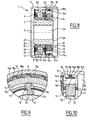
- the embodiment illustrated on the Figures 5 and 6 is similar to the above, except that the relative provisions of the free wheel 6 and the friction element 7 have been reversed, the friction element 7 is disposed between the cylindrical outer surface 2c of the sleeve 2 and the massive ring
- the wedging elements 15 are arranged between the track 14c formed on the outer cylindrical surface of the solid ring 14 and the bore 5b of the outer member 5.
- the operation is similar, with the exception of that the free wheel 6, in the jamming position, is integral with the outer element 5 and can move angularly relative to the sleeve 2 by sliding of the friction element 7.
- the embodiment illustrated on the figure 7 is to be compared with that illustrated on the Figures 1 to 4 , except that the friction element 7 is replaced by a circumferentially continuous friction element 18 fixed, for example by overmolding, on the outer ring 14 of the freewheel 6 between the ribs 14a and 14b and radially projecting towards the outside. 'outside.
- the friction element 18 is made of synthetic material. The choice of material and the radial prestressing of the friction element 18 between the solid ring 14 and the bore 5b of the outer element 5 determine the friction torque and therefore the maximum torque that can be transmitted between the outer element 5 and the outer element 5.
- Running tracks for the rolling elements 10 are formed directly on the sleeve 2 and on the outer member 5, respectively from the surfaces 2e and 5a.
- the axial surface 2e has an increased axial length with respect to the previous embodiments.
- the races are integral with the sleeve 2 and the outer member 5 respectively.
- the embodiment illustrated on the Figures 8 to 10 is similar to the one shown on the Figures 1 to 4 , except that the friction element 7 is replaced by a friction element 19 in the form of a sheet metal ring comprising radially resilient tongues 19a coming from the body 19b of the ring.
- the ring may be circumferentially continuous or present the shape of a band cut to good length and rolled on itself with its two ends end to end.
- the body 19b of the friction element 19 is disposed in contact with the solid ring 14 between the ribs 14a and 14b, while the tongues 19a, projecting radially outwardly, are in contact with the bore 9b of the element outside 5.
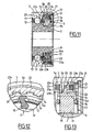
- the friction element 7 is replaced by an axially-acting friction device.
- the solid ring 14 of the freewheel 6 is of reduced radial thickness to leave a larger space for the torque limiting device 20 and is provided with an axial outer surface.
- a groove 21 is formed in the bore 5b of the outer member 5 to accommodate a circlip 22, near the free end of the bore 5b.
- the torque limiting device 20 which surrounds the solid ring 14 comprises two friction rings 23 comprising a friction portion 23a made of synthetic material and a support portion 23b, for example in the form of a flat metal washer.
- the friction portions 23a are secured to the support portion 23b for example by gluing or overmolding.
- the friction rings 23 are integral in rotation with the outer ring 14 of the freewheel 6 by means such as axial splines 24 cooperating with the bore of the support portions 23b of concordant shape.
- the friction rings 23 can move axially relative to the solid ring 14. Between the two friction rings 23 is disposed an axially acting washer 25, Belleville type washer or corrugated type.
- the torque limiting device 20 further comprises a cup-shaped ring 27 having an L-shaped section, fitted into the bore 5b of the outer element 5 and axially in abutting contact with the circlip 22 disposed in the groove 21.
- the ring 27 has a radial friction surface 27a.
- the friction portions 23a of the friction rings 23 have radial friction surfaces 23c, one in contact with the ring 27, and the other in contact with a radial surface 5c of the outer member 5 forming a shoulder between the bores 5a and 5b.
- the friction rings 23 are thus placed in elastic support against the corresponding friction surfaces of the outer element 5 and the ring 27 integral with the outer element 5.
- the choice of the material of the friction rings 23 and the prestressing axial of the rings by the washer 25 determines the friction torque and the maximum torque threshold transmittable. Of course, one could provide a variant comprising two washers 25 or a single ring 23 and a single washer 25.
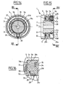
- the embodiment illustrated on the Figures 14 to 16 is close to the one shown on the Figures 1 to 4 , except that the freewheel 6 comprises a spring 28 provided with turns 29 in contact with the outer surface 2c of the sleeve 2 and one end 30 projecting outwards.
- the friction element 7 comprises a body 31 in the form of an open ring made of synthetic material and provided with an axial outer surface 31a in contact with the bore 5b of the outer element 5, a radial surface 31b connecting to the axial surface 31a, directed inward and in contact with the shoulder 5c of the outer member 5 and with a front radial surface of the outer ring 9 of the rolling bearing 4, an axial bore surface 31c fitted to the outer surface 2c of the sleeve 2 and a radial surface 31d disposed opposite the radial surface 31b and joining the inner axial 31c and outer 31a surfaces.
- the body 31 has a generally rectangular shape.
- an annular housing 32 disposed substantially at the center of the body 31 in the axial direction.
- a notch 33 occupying a small angular sector is formed between the housing 32 and the radial surface 31b in contact with the rolling bearing 4.
- the notch 33 opens on a radial front surface of the inner ring 8 of the rolling bearing 4.
- the turns 29 of the spring 28 are housed in the annular housing 32 while the outwardly projecting end 30 is housed in the notch 33.
- one of the free ends of the spring 28 is integral in rotation with the body 31 while the turns 29 are in frictional contact with the axial outer surface 2c of the sleeve 2.
- the spring tends to tighten and angularly secures said sleeve 2 and said body 31.
- the turns 29 tend to loosen.
- the sleeve 2 and the body 31 can freely rotate relative to each other in said relative direction of rotation with a slight friction of the turns 29 on the outer axial surface 2c of the sleeve 2.
- the body 31 further comprises another annular groove 34 formed from the radial surface 31d disposed opposite the rolling bearing 4 and having a slightly wider base radially than the inlet of said groove 34.
- a circlip 35 is disposed in the bottom of the groove 34 being radially temporarily shrunk during assembly.
- the groove 34 is dimensioned such that when the circlip 35 is in place in the bottom of the groove 34, said circlip 35 exerts on the body 31 a radially outward force.
- the body 31 being radially deformable by the material used and because said body 31 is an open ring, the outer surface 31a of the body 31 is prestressed radially on the bore 5b of the outer member 5, which ensures the joining together the body 31 and the outer member 5 to a certain torque which can be determined by the dimensions of the outer member 5, the body 31 and the circlip 35 as well as by their constituent materials.
- the body 31 forms a single element forming part of both the free wheel 6 and the friction element 7.
- the annular housing 32 and the notch 33 cooperate with the spring 28, and the axial outer surface 31a is in contact with the bore 5b of the outer member 5 with the possibility of sliding angularly with respect to said bore 5b in case of excessively high torque.
- the illustrated embodiments relate to freewheels whose wedging elements are cams or a spring.
- the invention could also operate with a free wheel whose wedging element or elements are one or pawls cooperating with a toothed track.
- the invention increases the longevity of the freewheel and mechanical members mounted upstream or downstream by filtering the torque peaks made by the friction member.
- the ring of the freewheel also cooperates with the friction member, hence a particularly compact assembly easy to transport, handle and mount in a mechanical assembly, for example between a cylindrical housing and a shaft.
Abstract
Description
La présente invention concerne le domaine des paliers comportant un embrayage unidirectionnel ou roue libre, généralement interposé entre un élément intérieur et un élément extérieur.The present invention relates to the field of bearings comprising a unidirectional clutch or freewheel, generally interposed between an inner element and an outer element.
La roue libre permet de transmettre un couple dans un sens et d'autoriser une rotation relative dans l'autre sens. Un palier peut être également interposé entre l'élément intérieur et l'élément extérieur pour supporter des charges radiales et éventuellement axiales. Le document
On connaît, par ailleurs, le document
Or, il serait bénéfique de limiter le couple transmis par une roue libre lorsque la roue libre est en position de blocage, notamment pour diminuer les sollicitations subies par d'autres éléments mobiles, et réduire leur fatigue. Le document
L'invention propose de limiter le couple transmis par une roue libre de façon simple et compacte.The invention proposes limiting the torque transmitted by a freewheel in a simple and compact manner.
L'invention propose un dispositif de roue libre à limiteur de couple facile à transporter et à manipuler et à intégrer dans un ensemble mécanique.The invention proposes a torque limiter freewheel device which is easy to transport and handle and to integrate into a mechanical assembly.
Le dispositif de roue libre, selon un aspect de l'invention, est du type comprenant un élément extérieur, un élément intérieur disposé dans l'élément extérieur, et une roue libre pourvue d'au moins un élément de coincement, disposée entre l'élément intérieur et l'élément extérieur pour laisser libre un mouvement de rotation dans un sens entre l'élément extérieur et l'élément intérieur et pour transmettre un couple dans l'autre sens entre l'élément extérieur et l'élément intérieur. La roue libre comprend une bague pourvue d'une surface intérieure cylindrique et d'une surface extérieure cylindrique, sensiblement alignées sur un plan radial perpendiculaire à l'axe de rotation du dispositif, et un organe limiteur de couple apte à limiter le couple transmis par la roue libre, l'organe limiteur de couple étant disposé radialement entre ladite bague et l'élément extérieur ou l'élément intérieur au contact de ladite bague et dudit élément.The freewheel device, according to one aspect of the invention, is of the type comprising an outer element, an inner element disposed in the outer element, and a freewheel provided with at least one wedging element, disposed between the inner element and the outer element to leave free a rotational movement in one direction between the outer member and the inner member and for transmitting torque in the other direction between the outer member and the inner member. The free wheel comprises a ring provided with a cylindrical inner surface and a cylindrical outer surface, substantially aligned on a radial plane perpendicular to the axis of rotation of the device, and a torque limiting member adapted to limit the torque transmitted by the free wheel, the torque limiting member being disposed radially between said ring and the outer member or the inner member in contact with said ring and said element.
Une piste de glissement peut être formée sur la surface intérieure cylindrique ou la surface extérieure cylindrique, l'organe limiteur de couple étant disposé en contact avec la surface extérieure cylindrique ou la surface intérieure cylindrique respectivement. La roue libre et l'organe limiteur de couple sont ainsi associés de façon peu encombrante.A sliding track may be formed on the cylindrical inner surface or the cylindrical outer surface, the torque limiting member being disposed in contact with the cylindrical outer surface or the cylindrical inner surface respectively. The free wheel and the torque limiting member are thus associated in a compact manner.
L'invention peut utiliser tout type de roue libre connu à cames basculantes, à rouleaux, à ressort, ou à cliquet.The invention can use any type of known freewheel cams, roller, spring, or ratchet.
Dans un mode de réalisation de l'invention, l'organe limiteur de couple est monté en série avec la roue libre pour limiter le couple transmis par l'organe d'engagement unidirectionnel en position de transmission de couple.In one embodiment of the invention, the torque limiting member is mounted in series with the freewheel to limit the torque transmitted by the unidirectional engagement member in the torque transmission position.
Dans un mode de réalisation de l'invention, l'organe limiteur de couple comprend au moins un élément de friction. L'élément de friction peut comprendre une surface radiale de friction. L'élément de friction peut comprendre une surface axiale de friction délimitée par deux plans radiaux.In one embodiment of the invention, the torque limiting member comprises at least one friction element. The friction element may comprise a radial friction surface. The friction element may comprise an axial friction surface delimited by two radial planes.
Le dispositif comprend un palier permettant à l'élément extérieur de tourner par rapport à l'élément intérieur. Le palier est un palier à roulement. Des pistes de roulement pour des éléments roulants dudit palier sont ménagées dans les éléments intérieur et extérieur. Alternativement, les pistes de roulement sont ménagées dans des bagues intérieure et extérieure solidaire des éléments intérieur et extérieur.The device includes a bearing allowing the outer member to rotate relative to the inner member. The bearing is a rolling bearing. Running tracks for rolling elements of said bearing are provided in the inner and outer elements. Alternatively, the raceways are formed in inner and outer rings secured to the inner and outer elements.
Dans un mode de réalisation de l'invention, l'organe limiteur de couple est disposé sur une surface extérieure de la roue libre.In one embodiment of the invention, the torque limiting member is disposed on an outer surface of the freewheel.
Dans un autre mode de réalisation de l'invention, l'organe limiteur de couple est disposé dans un alésage de la roue libre.In another embodiment of the invention, the torque limiting member is disposed in a bore of the freewheel.
Dans un mode de réalisation de l'invention, l'organe limiteur de couple comprend un anneau élastique ouvert pourvu d'une surface extérieure de frottement et d'une surface intérieure de frottement. L'anneau peut être réalisé en tôle d'acier et peut présenter une section en U pourvue de deux ailes axiales.In one embodiment of the invention, the torque limiting member comprises an open elastic ring provided with an outer friction surface and an inner friction surface. The ring may be made of sheet steel and may have a U-section provided with two axial wings.
Dans un mode de réalisation de l'invention, l'organe limiteur de couple comprend une pluralité de languettes élastiques de frottement.In one embodiment of the invention, the torque limiting member comprises a plurality of resilient friction tabs.
Dans un autre mode de réalisation de l'invention, l'organe limiteur de couple comprend un anneau élastique en matériau synthétique pourvu d'une surface extérieure ou intérieure de frottement et d'une surface respectivement intérieure ou extérieure de fixation.In another embodiment of the invention, the torque limiting member comprises a resilient ring of synthetic material provided with an outer or inner friction surface and an inner or outer fixing surface respectively.
Dans un mode de réalisation de l'invention, l'organe limiteur de couple comprend au moins un anneau de friction et une rondelle élastique de mise en appui axial de l'anneau de friction sur une surface de friction. L'organe limiteur de couple peut comprendre deux anneaux de friction entre lesquels est montée ladite rondelle élastique. Les anneaux de friction peuvent présenter des surfaces radiales de friction.In one embodiment of the invention, the torque limiting member comprises at least one friction ring and an elastic washer for axially pressing the friction ring on a friction surface. The torque limiting member may comprise two friction rings between which is mounted said elastic washer. The friction rings may have radial friction surfaces.
Dans un mode de réalisation de l'invention, l'organe limiteur de couple comprend un corps en forme d'anneau ouvert. La bague de la roue libre et le corps de l'organe limiteur de couple peuvent être constitués par un seul élément dont la surface extérieure est en contact avec l'élément extérieur avec frottement en cas de rotation angulaire, et dont la surface intérieure coopère avec l'élément de coincement, ou dont la surface intérieure est en contact avec l'élément intérieur avec frottement en cas de rotation angulaire, et dont la surface extérieure coopère avec l'élément de coincement.In one embodiment of the invention, the torque limiting member comprises an open ring-shaped body. The ring of the freewheel and the body of the torque limiting member may be constituted by a single element whose outer surface is in contact with the outer element with friction in the case of angular rotation, and whose inner surface cooperates with the wedging element, or whose inner surface is in contact with the inner element with friction in case of angular rotation, and whose outer surface cooperates with the wedging element.
Dans un mode de réalisation de l'invention, l'organe limiteur de couple comprend, en outre, un élément élastique de mise en précontrainte dudit corps. L'élément élastique peut être un anneau du type circlips.In one embodiment of the invention, the torque limiting member further comprises a resilient biasing member of said body. The elastic element may be a ring of the circlip type.
Dans un mode de réalisation de l'invention, la roue libre comprend un ressort pourvu d'une extrémité solidaire de l'organe limiteur de couple et de spires en contact de frottement sur l'élément intérieur ou extérieur.In one embodiment of the invention, the freewheel comprises a spring provided with an integral end of the torque limiting member and turns in frictional contact with the inner or outer element.
Dans un mode de réalisation de l'invention, les éléments de coincement de la roue libre sont des cames, des rouleaux ou des cliquets.In one embodiment of the invention, the locking elements of the freewheel are cams, rollers or pawls.
Dans un mode de réalisation de l'invention, l'organe limiteur de couple comprend un élément de friction et un élément de mise en précontrainte de l'élément de friction contre ladite bague et/ou l'élément extérieur ou l'élément intérieur. Plus particulièrement, l'élément de friction peut être mis en précontrainte entre ladite bague et l'élément extérieur, entre ladite bague et l'élément intérieur, entre deux surfaces solidaires de l'élément extérieur, ou encore entre deux surfaces solidaires de l'élément intérieur. L'élément de mise en précontrainte est, avantageusement, une pièce distincte de l'élément de friction.In one embodiment of the invention, the torque limiting member comprises a friction element and a biasing element of the friction element against said ring and / or the outer element or the inner element. More particularly, the friction element can be prestressed between said ring and the outer element, between said ring and the inner element, between two integral surfaces of the outer element, or between two integral surfaces of the outer element. interior element. The prestressing element is advantageously a separate part of the friction element.
Dans un mode de réalisation de l'invention, l'organe limiteur de couple est en précontrainte entre deux pièces distinctes dans des directions opposées. Plus particulièrement, l'organe limiteur de couple peut être en précontrainte radialement vers l'extérieur contre l'élément extérieur et radialement vers l'intérieur contre ladite bague, radialement vers l'extérieur contre ladite bague et radialement vers l'intérieur contre l'élément intérieur, ou axialement contre deux surfaces opposées solidaires de l'élément extérieur ou de l'élément intérieur.In one embodiment of the invention, the torque limiting member is prestressed between two separate parts in opposite directions. More particularly, the torque limiting member may be preloaded radially outwardly against the outer member and radially inwardly against said ring, radially outwardly against said ring and radially inwardly against the ring. inner member, or axially against two opposed surfaces integral with the outer member or the inner member.
On entend ici par roue libre un dispositif de transmission d'un couple dans un sens et de rotation relative dans l'autre sens, avec éventuellement un couple de traînée résiduel négligeable en conditions normales de fonctionnement, entre un élément d'entrée et un élément de sortie du dispositif.The term "freewheel" here means a device for transmitting a torque in one direction and relative rotation in the other direction, possibly with negligible residual drag torque under normal operating conditions, between an input element and an element. output of the device.
Grâce à l'invention, on limite l'encombrement du dispositif qui se présente sous la forme d'une cartouche compacte prémontée relativement bien protégée contre les éléments extérieurs. La durée de vie des pièces mobiles en amont et en aval de la roue libre est allongée grâce à l'écrêtement des pics de couple, d'où une économie de fonctionnement et une réduction du risque de bris.Thanks to the invention, it limits the size of the device which is in the form of a pre-assembled compact cartridge relatively well protected against the external elements. The duration of The life of the moving parts upstream and downstream of the freewheel is lengthened by the clipping of torque peaks, resulting in a saving in operation and a reduction in the risk of breakage.
L'invention sera mieux comprise à l'étude de la description détaillée de quelques modes de réalisation pris à titre d'exemples nullement limitatifs et illustrés par les dessins annexés, sur lesquels :
- la
figure 1 est une vue en coupe axiale d'un dispositif de roue libre selon un premier mode de réalisation de l'invention ; - la
figure 2 est une vue de détail de lafigure 1 ; - la
figure 3 est une vue en coupe transversale selon un plan passant par les éléments de coincement du dispositif de lafigure 1 ; - la
figure 4 est une vue de détail de lafigure 3 ; - la
figure 5 est une vue en coupe axiale d'un dispositif de roue libre selon un deuxième mode de réalisation de l'invention ; - la
figure 6 est une vue de détail de lafigure 5 ; - la
figure 7 est une vue en coupe axiale d'un dispositif de roue libre selon un troisième mode de réalisation ; - la
figure 8 est une vue en coupe axiale d'un dispositif de roue libre selon un quatrième mode de réalisation de l'invention ; - la
figure 9 est une vue de détail du dispositif de roue libre de lafigure 8 pris en coupe transversale selon un plan passant par les éléments de coincement ; - la
figure 10 est une vue de détail de lafigure 8 ; - la
figure 11 est une vue en coupe axiale d'un dispositif de roue libre selon un cinquième mode de réalisation de l'invention; - la
figure 12 est une vue de détail du dispositif de roue libre de lafigure 11 pris en coupe transversale selon un plan passant par les éléments de coincement ; - la
figure 13 est une vue de détail de lafigure 11 ; - la
figure 14 est une vue en coupe selon XIV-XIV de lafigure 15 d'un dispositif de roue libre selon un sixième mode de réalisation de l'invention ; - la
figure 15 est une vue en coupe selon XV-XV de lafigure 14 ; et - la
figure 16 est une vue de détail de lafigure 15 .
- the
figure 1 is an axial sectional view of a freewheel device according to a first embodiment of the invention; - the
figure 2 is a detail view of thefigure 1 ; - the
figure 3 is a cross-sectional view along a plane passing through the wedging elements of the device of thefigure 1 ; - the
figure 4 is a detail view of thefigure 3 ; - the
figure 5 is an axial sectional view of a freewheel device according to a second embodiment of the invention; - the
figure 6 is a detail view of thefigure 5 ; - the
figure 7 is an axial sectional view of a freewheel device according to a third embodiment; - the
figure 8 is an axial sectional view of a freewheel device according to a fourth embodiment of the invention; - the
figure 9 is a detailed view of the freewheel device of thefigure 8 taken in cross section along a plane passing through the wedging elements; - the
figure 10 is a detail view of thefigure 8 ; - the
figure 11 is an axial sectional view of a freewheel device according to a fifth embodiment of the invention; - the
figure 12 is a detailed view of the freewheel device of thefigure 11 taken in cross section along a plane passing through the wedging elements; - the
figure 13 is a detail view of thefigure 11 ; - the
figure 14 is a sectional view according to XIV-XIV of thefigure 15 a freewheel device according to a sixth embodiment of the invention; - the
figure 15 is a sectional view according to XV-XV of thefigure 14 ; and - the
figure 16 is a detail view of thefigure 15 .
Comme on peut le voir sur les
Le manchon 2 comprend un alésage 2a, une surface radiale frontale 2b, une surface extérieure cylindrique 2c s'étendant sur la majeure partie de sa longueur à partir de la surface radiale d'extrémité 2b, une surface radiale 2d s'étendant vers l'extérieur à partir de l'extrémité de la surface extérieure cylindrique 2c, une surface axiale 2e de faible longueur s'étendant à partir de l'extrémité libre de la portion radiale 2d, axialement à l'opposé de la surface radiale d'extrémité 2b, et une surface radiale d'extrémité 2f opposée à la surface radiale d'extrémité 2b.The
Le roulement 4 peut être de type standard, à faible coût de fabrication et comprend une bague intérieure massive 8 pourvue d'un alésage monté, par exemple par emmanchement, sur la surface cylindrique extérieure 2c du manchon 2, et en contact avec la portion radiale 2d, une bague extérieure massive 9, une rangée d'éléments roulants 10, ici des billes, disposés entre une piste de roulement de la bague intérieure 8 et une piste de roulement de la bague extérieure 9, une cage 11 de maintien de l'espacement circonférentiel des éléments roulants 10 et des joints d'étanchéité 12 et 13 solidaires de la bague extérieure 9 et frottant sur une portée cylindrique de la bague intérieure 8, disposés d'un côté et de l'autre de la rangée d'éléments roulants 10 pour empêcher l'intrusion d'éléments étrangers à proximité des éléments roulants 10 et pour conserver un produit lubrifiant tel que de la graisse à l'intérieur du roulement et à proximité des éléments roulants 10. La bague extérieure 9 est pourvue d'une surface cylindrique extérieure 9a, coaxiale à la surface cylindrique extérieure 2c du manchon 2.The
L'élément extérieur 5 comprend un alésage central 5a monté, par exemple par emmanchement, sur la surface cylindrique extérieure 9a de la bague extérieure 9. Le palier à roulement 4 assure ainsi la liberté de rotation de l'élément extérieur 5 par rapport au manchon 2, et la reprise des efforts radiaux. L'élément extérieur 5 comprend en outre un alésage 5b, de diamètre très légèrement supérieur à l' alésage central 5a, et disposé à l'extrémité axiale de l'élément extérieur 5 située à l'opposé du support 4. Le roulement 4 et l'élément extérieur 5 sont asymétriques par rapport à un plan radial passant par le centre des éléments roulants 10. Une surface radiale annulaire 5c est formée entre les alésages 5a et 5b.The
La roue libre 6, montée adjacente au palier à roulement 4, comprend une bague extérieure 14, par exemple de type massive, dont l'alésage forme une piste de glissement 14c, une rangée d'éléments de coincement 15, ici des cames, une cage 16 pourvue de fenêtres dans lesquelles sont disposés les éléments de coincement 15 sous la forme de cames et un ressort 17 de rappel des éléments de coincement 15 maintenant lesdits éléments de coincement en contact permanent avec les pistes. Les éléments de coincement 15 sont disposés radialement entre la surface cylindrique extérieure 2c du manchon 2 et la piste 14c de la bague extérieure 14 axialement entre le palier à roulement 4 et la surface radiale 2b d'extrémité du manchon 2,The
Entre la périphérie de la bague extérieure 14 et l'alésage 5b de l'élément extérieur 5, subsiste un espace radial dans lequel est disposé l'élément de friction 7. Plus précisément, la bague extérieure 14 comprend deux nervures circulaires 14a, 14b, dirigées radialement vers l'extérieur. Les nervures 14a et 14b sont disposées axialement aux extrémités de la bague extérieure 14 en étant alignées avec les surfaces radiales d'extrémités de la bague extérieure 14 et entourent une surface axiale extérieure 14d de la bague extérieure 14. L'élément de friction 7 est disposé entre les nervures 14a et 14b et est ainsi solidaire axialement de la bague extérieure 14.Between the periphery of the
L'élément de friction 7 se présente sous la forme d'un anneau ouvert sur un faible secteur angulaire, par exemple de l'ordre de quelques degrés. L'élément de friction 7 présente en section droite axiale une forme de U pourvue de deux ailes axiales et peut être réalisé en tôle roulée. En d'autres termes, l'élément de friction 7, en section axiale, comprend une portion axiale 7a de faible diamètre, une portion radiale 7b s'étendant vers l'extérieur à partir d'une extrémité de la portion axiale 7a, une portion axiale 7c s'étendant à l'opposé de la section axiale 7a à partir de l'extrémité de grand diamètre de la portion radiale 7b, une portion radiale 7d s'étendant vers l'intérieur à partir de l'extrémité libre de la portion axiale 7c et une portion axiale 7e s'étendant à l'opposé de la portion axiale 7a à partir de l'extrémité de petit diamètre de la portion radiale 7b. Les portions axiales 7a et 7e présentent un diamètre sensiblement identique et sont en contact avec la surface extérieure de la bague massive 14, l'extrémité libre de la portion axiale 7a étant disposée à proximité de la nervure 14a et l'extrémité libre de la portion axiale 7e étant disposée à proximité de la nervure 14b. L'élément de friction 7 est symétrique par rapport à un plan radial passant par le milieu de la portion axiale 7c. La portion axiale 7c est en contact avec l'alésage 9b de l'élément extérieur 5. L'élément de friction 7 peut être pourvu d'un revêtement local ou général pour améliorer ses propriétés de friction ou anti-corrosion.The
Le fonctionnement du dispositif sera mieux compris d'après la
Lorsque l'élément extérieur 5 tourne dans le sens horaire par rapport au manchon 2, la roue libre 6 se met en position de blocage, les cames de coincement 15 prenant appui sur la surface extérieure cylindrique 2c du manchon 2 et sur la piste 14c de la bague massive 14. Le manchon 2 est donc soumis à un couple qui peut être élevé et qui tend à le faire tourner dans le sens horaire. Toutefois, lorsque le couple transmis de l'élément extérieur 5 à l'élément de friction 7, de l'élément de friction 7 à la roue libre 6 et de la roue libre 6 au manchon 2, dépasse un seuil prédéterminé, l'élément de friction 7 se met à glisser, par rapport à la bague massive 14 et/ou par rapport à l'élément extérieur 5, et assure ainsi un écrêtement du couple transmis à l'élément extérieur 5. Le seuil prédéterminé de couple peut être choisi au montage et dépend des caractéristiques de l'élément de friction et des surfaces avec lesquelles ledit élément de friction est en contact.When the
Par analogie avec un système électrique, l'ensemble formé par la roue libre 6 et l'élément de friction 7 limiteur de couple, peut être vu comme une diode Zener qui autorise librement le passage du courant électrique dans un sens et l'interdit dans l'autre jusqu'à ce qu'une certaine tension soit atteinte, tension au-delà de laquelle le courant peut à nouveau passer librement.By analogy with an electrical system, the assembly formed by the
Ainsi, la mise en série de l'élément de friction 7 et de la roue libre 6 permet, d'une part, d'autoriser une rotation libre dans un sens, et d'interdire la rotation dans le sens opposé dans la limite d'un couple maximal au-delà duquel la rotation est à nouveau autorisée avec en sus des pertes par frottement de l'élément de friction 7 sur la bague extérieure 14 et sur l'alésage 5b de l'élément extérieur 5.Thus, putting the
Le mode de réalisation illustré sur les
Le mode de réalisation illustré sur la
Le mode de réalisation illustré sur les
Dans le mode de réalisation illustré sur les
Le dispositif de limitation de couple 20 qui entoure la bague massive 14 comprend deux anneaux de friction 23 comprenant une portion de friction 23a réalisée en matériau synthétique et une portion de support 23b, par exemple sous la forme d'une rondelle plate métallique. Les portions de friction 23a sont solidarisées à la portion de support 23b par exemple par collage ou surmoulage. Les anneaux de friction 23 sont solidaires en rotation de la bague extérieure 14 de la roue libre 6 par des moyens tels que des cannelures axiales 24 coopérant avec l'alésage des portions de support 23b de forme concordante. Les anneaux de friction 23 peuvent se déplacer axialement par rapport à la bague massive 14. Entre les deux anneaux de friction 23, est disposée une rondelle à action axiale 25, du type rondelle Belleville ou encore de type ondulé. Le dispositif de limitation de couple 20 comprend en outre un anneau 27 en forme de coupelle à section en L, emmanché dans l'alésage 5b de l'élément extérieur 5 et axialement en contact de butée contre le circlips 22 disposé dans la rainure 21. L'anneau 27 comporte une surface radiale de friction 27a.The
Les portions de friction 23a des anneaux de friction 23 présentent des surfaces radiales de friction 23c, l'une en contact avec l'anneau 27, et l'autre en contact avec une surface radiale 5c de l'élément extérieur 5 formant un épaulement entre les alésages 5a et 5b. Les anneaux de friction 23 sont donc mis en appui élastique contre les surfaces de friction correspondantes de l'élément extérieur 5 et de l'anneau 27 solidaire de l'élément extérieur 5. Le choix du matériau des anneaux de friction 23 et de la précontrainte axiale des anneaux par la rondelle 25 détermine le couple de friction et le seuil de couple maximal transmissible. Bien entendu, on pourrait prévoir une variante comprenant deux rondelles 25 ou encore un seul anneau 23 et une seule rondelle 25.The
Le mode de réalisation illustré sur les
Toutefois, dans la surface axiale intérieure 31c est ménagée un logement annulaire 32 disposée sensiblement au centre du corps 31 dans le sens axial. En outre, une encoche 33 occupant un faible secteur angulaire est ménagée entre le logement 32 et la surface radiale 31b en contact avec le palier à roulement 4. L'encoche 33 débouche sur une surface radiale frontale de la bague intérieure 8 du palier à roulement 4. Les spires 29 du ressort 28 sont logées dans le logement annulaire 32 tandis que l'extrémité 30 en saillie vers l'extérieur est logée dans l'encoche 33.However, in the inner
Ainsi, l'une des extrémités libres du ressort 28 est solidaire en rotation du corps 31 tandis que les spires 29 sont en contact avec frottement sur la surface extérieure axiale 2c du manchon 2. Il en résulte que dans un sens de rotation relative entre le manchon 2 et le corps 31, le ressort tend à serrer et solidarise angulairement ledit manchon 2 et ledit corps 31. Au contraire, dans le sens de rotation relative opposé, les spires 29 ont tendance à se desserrer. Le manchon 2 et le corps 31 peuvent tourner librement l'un par rapport à l'autre dans ledit sens de rotation relative avec un léger frottement des spires 29 sur le surface axiale extérieure 2c du manchon 2.Thus, one of the free ends of the
Le corps 31 comprend en outre une autre rainure annulaire 34 ménagée à partir de la surface radiale 31d disposée à l'opposé du palier à roulement 4 et présentant un fond légèrement plus étendu radialement que l'entrée de ladite rainure 34. Un circlips 35 est disposé dans le fond de la rainure 34 en étant radialement rétreint temporairement lors de son montage. La rainure 34 est dimensionnée de telle sorte que lorsque le circlips 35 est en place dans le fond de la rainure 34, ledit circlips 35 exerce sur le corps 31 un effort radial vers l'extérieur. Le corps 31 étant radialement déformable de par le matériau utilisé et du fait que ledit corps 31 soit un anneau ouvert, la surface extérieure 31a du corps 31 est précontrainte radialement sur l'alésage 5b de l'élément extérieur 5, ce qui garantit la solidarisation du corps 31 et de l'élément extérieur 5 jusqu'à un certain couple qui peut être déterminé par les dimensions de l'élément extérieur 5, du corps 31 et du circlips 35 ainsi que par leurs matériaux constitutifs.The
En d'autres termes, le corps 31 forme un élément unique faisant partie à la fois de la roue libre 6 et de l'élément de friction 7. En effet, le logement annulaire 32 et l'encoche 33 coopèrent avec le ressort 28, et la surface extérieure axiale 31a est en contact avec l'alésage 5b de l'élément extérieur 5 avec possibilité de glisser angulairement par rapport audit alésage 5b en cas de couple trop élevé.In other words, the
Ainsi, en fonctionnement de prise de couple, au-delà d'une certaine valeur de couple, le corps 31 de l'élément de friction 7 se met à tourner par rapport à l'élément extérieur 5, limitant ainsi à la valeur prédéterminée le couple transmis.Thus, in torque-taking operation, beyond a certain torque value, the
Les modes de réalisation illustrés concernent des roues libres dont les éléments de coincement sont des cames ou un ressort. Bien entendu, l'invention pourrait également fonctionner avec une roue libre dont le ou les éléments de coincement sont un ou des cliquets coopérant avec une piste crantée.The illustrated embodiments relate to freewheels whose wedging elements are cams or a spring. Of course, the invention could also operate with a free wheel whose wedging element or elements are one or pawls cooperating with a toothed track.
Grâce à l'invention, on accroît la longévité de la roue libre et des organes mécaniques montés en amont ou en aval par le filtrage des pics de couple effectué par l'organe de friction. La bague de la roue libre coopère également avec l'organe de friction, d'où un ensemble particulièrement compact facile à transporter, à manipuler et à monter dans un ensemble mécanique, par exemple entre un logement cylindrique et un arbre.Thanks to the invention, it increases the longevity of the freewheel and mechanical members mounted upstream or downstream by filtering the torque peaks made by the friction member. The ring of the freewheel also cooperates with the friction member, hence a particularly compact assembly easy to transport, handle and mount in a mechanical assembly, for example between a cylindrical housing and a shaft.
Claims (19)
- Freewheel bearing device (1), comprising an outer element (5), an inner element placed in the outer element, and a free wheel (6) provided with at least one jamming element (15), placed between the inner element and the outer element to leave free a rotation movement in one direction between the outer element and the inner element and to transmit a torque in the other direction between the outer element and the inner element, the free wheel (6) comprising a race (14) provided with an inner cylindrical surface and an outer cylindrical surface (14d), substantially aligned on a radial plane perpendicular to the axis of rotation of the device, and a torque limiter member capable of limiting the torque transmitted by the free wheel, the torque limiter member being placed radially between said race (14) and the outer element (5) or the inner element in contact with said race and said element, characterized in that it comprises a rolling bearing allowing the outer element to rotate relative to the inner element, the freewheel being adjacent to the rolling bearing (4) mounted on the inner element, the outer element (5) being mounted on the rolling bearing.
- Device according to Claim 1, characterized in that the torque limiter member is mounted in series with the free wheel (6) to limit the torque transmitted by the unidirectional engagement member in the torque transmission position.
- Device according to Claim 1 or 2, characterized in that the torque limiter member comprises at least one friction element (7).
- Device according to Claim 3, characterized in that the friction element (20) comprises a radial friction surface (23a).
- Device according to Claim 3, characterized in that the friction element (7) comprises an axial friction surface delimited by two radial planes.
- Device according to Claim 1, characterized in that raceways for the rolling elements of said bearing are arranged in the inner and outer elements.
- Device according to any one of the preceding claims, characterized in that the torque limiter member is placed on an outer surface (14d) of the free wheel.
- Device according to any one of Claims 1 to 6, characterized in that the torque limiter member is placed in a bore of the free wheel.
- Device according to any one of the preceding claims, characterized in that the torque limiter member comprises an open elastic ring provided with an outer friction surface and an inner friction surface.
- Device according to Claim 9, characterized in that the ring is made of steel sheet and has a U-channel provided with two axial flanges.
- Device according to any one of the preceding claims, characterized in that the torque limiter member comprises a plurality of elastic tongues (19a).
- Device according to any one of the preceding claims, characterized in that the torque limiter member comprises an elastic ring (18) made of synthetic material provided with an outer or inner friction surface and a respectively inner or outer attachment surface.
- Device according to any one of the preceding claims, characterized in that the torque limiter member comprises at least one friction ring (23) and an elastic washer (25) for placing the friction ring bearing axially on a friction surface.
- Device according to any one of Claims 1 to 9, characterized in that the torque limiter member comprises a body in the shape of an open ring.
- Device according to Claim 14, characterized in that the torque limiter member also comprises an elastic element for prestressing said body.
- Device according to any one of the preceding claims, characterized in that the free wheel comprises a spring provided with an end fixedly attached to the torque limiter member and coils in friction contact on the inner or outer element.
- Device according to any one of the preceding claims, characterized in that the jamming elements of the free wheel are cams, rollers or pawls.
- Device according to any one of the preceding claims, characterized in that the torque limiter member comprises a friction element and an element for prestressing the friction element against said race (14) and/or the outer element (5) or the inner element.
- Device according to any one of the preceding claims, characterized in that the torque limiter member is prestressed between two separate pieces.
Applications Claiming Priority (2)
| Application Number | Priority Date | Filing Date | Title |
|---|---|---|---|
| FR0309239A FR2858376B1 (en) | 2003-07-28 | 2003-07-28 | FREEWHEEL BEARING DEVICE WITH TORQUE LIMITER. |
| PCT/FR2004/001609 WO2005021991A1 (en) | 2003-07-28 | 2004-06-25 | Freewheel bearing device with torque limiter |
Publications (2)
| Publication Number | Publication Date |
|---|---|
| EP1651878A1 EP1651878A1 (en) | 2006-05-03 |
| EP1651878B1 true EP1651878B1 (en) | 2008-08-27 |
Family
ID=34043593
Family Applications (1)
| Application Number | Title | Priority Date | Filing Date |
|---|---|---|---|
| EP04767457A Not-in-force EP1651878B1 (en) | 2003-07-28 | 2004-06-25 | Freewheel bearing device with torque limiter |
Country Status (6)
| Country | Link |
|---|---|
| US (2) | US7766140B2 (en) |
| EP (1) | EP1651878B1 (en) |
| AT (1) | ATE406526T1 (en) |
| DE (1) | DE602004016171D1 (en) |
| FR (1) | FR2858376B1 (en) |
| WO (1) | WO2005021991A1 (en) |
Families Citing this family (20)
| Publication number | Priority date | Publication date | Assignee | Title |
|---|---|---|---|---|
| FR2858376B1 (en) * | 2003-07-28 | 2006-03-03 | Skf France | FREEWHEEL BEARING DEVICE WITH TORQUE LIMITER. |
| FR2902699B1 (en) | 2006-06-26 | 2010-10-22 | Skf Ab | SUSPENSION STOP DEVICE AND FORCE LEG. |
| FR2906587B1 (en) | 2006-10-03 | 2009-07-10 | Skf Ab | TENDERING ROLLER DEVICE. |
| FR2913081B1 (en) | 2007-02-27 | 2009-05-15 | Skf Ab | DEBRAYABLE PULLEY DEVICE |
| FR2914381B1 (en) * | 2007-03-26 | 2009-07-03 | Skf Ab | DEBRAYABLE PULLEY DEVICE. |
| FR2932859B1 (en) * | 2008-06-19 | 2010-12-10 | Skf Ab | TORQUE TRANSMISSION DEVICE, IN PARTICULAR FOR A CLIMATE COMPRESSOR |
| ITPD20080253A1 (en) | 2008-08-20 | 2010-02-21 | Clerprem Spa | ADJUSTABLE ARMREST IN INCLINATION, IN PARTICULAR FOR VEHICLES |
| CN102187108B (en) * | 2008-09-15 | 2013-09-18 | 麦格纳动力系有限公司 | Sealed one way roller clutch |
| CN102209858B (en) | 2008-11-10 | 2014-07-09 | 舍弗勒技术股份两合公司 | Clamping body freewheel |
| DE102009009528A1 (en) * | 2009-02-18 | 2010-08-19 | Schaeffler Technologies Gmbh & Co. Kg | Pulley with overrunning clutch |
| US8376900B2 (en) | 2009-12-17 | 2013-02-19 | GM Global Technology Operations LLC | Clutch assembly |
| WO2012024660A2 (en) * | 2010-08-20 | 2012-02-23 | Seektech, Inc. | Asymmetric drag force bearings for use with push-cable storage drums |
| DE102011081661B4 (en) * | 2011-08-26 | 2023-11-30 | Robert Bosch Gmbh | Switchable gearbox for a hand-held machine tool |
| FR3014038B1 (en) * | 2013-11-29 | 2017-03-10 | Ifp Energies Now | DEVICE FOR ASSEMBLING A UNIDIRECTIONAL AUTOMATIC COUPLING WITH ELEMENTS THAT DOOR AND MOTOR POWERTRAIN USING SUCH A DEVICE. |
| EP3456993B1 (en) * | 2017-09-14 | 2020-06-24 | Goodrich Actuation Systems Limited | Torque transmission device |
| JP2019078308A (en) * | 2017-10-23 | 2019-05-23 | Nskワーナー株式会社 | One-way clutch |
| CN107943288B (en) * | 2017-11-16 | 2020-10-16 | 陈昭胜 | Intelligent wearing device, intelligent wearing equipment and control method |
| JP6886661B2 (en) * | 2017-12-26 | 2021-06-16 | 株式会社クボタ | Work machine |
| DE102020107597B4 (en) * | 2020-03-19 | 2024-03-21 | Nidec Corporation | Actuator of a motor vehicle automatic transmission |
| US11512744B2 (en) * | 2020-03-26 | 2022-11-29 | Nsk-Warner K.K. | Clutch apparatus |
Family Cites Families (117)
| Publication number | Priority date | Publication date | Assignee | Title |
|---|---|---|---|---|
| DE916370C (en) * | 1951-08-08 | 1954-08-09 | Star Kugelhalter Ges M B H Deu | Overload clutch |
| US3926286A (en) * | 1973-02-05 | 1975-12-16 | Reell Precision Mfg | Spring grip clutch |
| FR2304829A1 (en) * | 1975-03-21 | 1976-10-15 | Ferodo Sa | RELEASE STOP |
| US4046238A (en) * | 1976-02-03 | 1977-09-06 | Mendoza Orozco Hector | Free-wheeling mechanism for bicycles |
| US4319220A (en) * | 1976-08-31 | 1982-03-09 | Dennis G. Pappas | Alarm system for monitoring pressurized vehicular tires |
| DE2658748A1 (en) | 1976-12-24 | 1978-06-29 | Kugelfischer G Schaefer & Co | ROLLER BEARING, PREFERABLY AXIAL BEARING, FOR ROTATING THE SPRING PAD OF VEHICLE WHEELS |
| JPS57161344A (en) * | 1981-03-27 | 1982-10-04 | Nippon Denso Co Ltd | Belt tension control device |
| JPS58145522A (en) * | 1982-02-20 | 1983-08-30 | Honda Motor Co Ltd | Motive power transmission device for vehicle |
| US4601374A (en) * | 1982-04-22 | 1986-07-22 | Federal-Mogul Corporation | Hydraulic clutch piston and seal |
| FR2544429B1 (en) * | 1983-04-15 | 1985-08-02 | Valeo | METHOD FOR MOUNTING A RELEASE STOPPER, AND CORRESPONDING RELEASE STOPPER, PARTICULARLY FOR A MOTOR VEHICLE |
| DE3445541A1 (en) * | 1984-01-04 | 1985-07-11 | Skandiafabriken AB, Mullsjö | LIQUID LEVEL INDICATOR |
| GB8407519D0 (en) | 1984-03-22 | 1984-05-02 | Cambridge Electronic Ind | Tachogenerators |
| FR2577291B1 (en) | 1985-02-08 | 1989-10-13 | Valeo | SELF-CENTERING CLUTCH STOPPER, PARTICULARLY FOR MOTOR VEHICLE, WITH SIMPLIFIED COMPACT ASSEMBLY |
| US5033013A (en) * | 1985-04-22 | 1991-07-16 | Yamasa Tokei Meter Co., Ltd. | Method and apparatus for measuring the amount of exercise |
| US4699530A (en) * | 1985-06-28 | 1987-10-13 | Oiless Industry Co., Ltd. | Thrust ball bearing unit |
| DE3534462A1 (en) | 1985-09-27 | 1987-04-02 | Bosch Gmbh Robert | Warning device for detecting damage on moving parts |
| FR2602872B1 (en) | 1986-08-05 | 1989-03-31 | Renault | ANGULAR SPEED SENSOR AND ITS APPLICATION TO A COMBINED TORQUE AND ANGULAR SPEED SENSOR FOR A STEERING COLUMN OF A MOTOR VEHICLE |
| EP0272544B1 (en) * | 1986-12-22 | 1990-09-26 | Siemens Aktiengesellschaft | Angular-position encoder with a photo-electrically palpable encoder disc and double axle bearing |
| FR2609126B1 (en) * | 1986-12-29 | 1989-10-27 | Valeo | RELEASE STOP, ESPECIALLY FOR A MOTOR VEHICLE |
| FR2611009B1 (en) * | 1987-02-17 | 1989-05-19 | Valeo | RELEASE STOP, ESPECIALLY FOR A MOTOR VEHICLE |
| FR2611244B1 (en) | 1987-02-20 | 1991-07-05 | Valeo | RELEASE CLUTCH WITH ELASTIC PIECE WITH AXIAL ACTION, IN PARTICULAR FOR A MOTOR VEHICLE |
| JPS63246516A (en) * | 1987-04-02 | 1988-10-13 | Nippon Seiko Kk | Clutch release bearing device |
| FR2615568B1 (en) | 1987-05-21 | 1991-10-31 | Equip Electr Moteur | FREEWHEEL STARTER LAUNCHER COMPRISING A TORQUE LIMITER |
| US4815867A (en) * | 1987-09-23 | 1989-03-28 | Federal-Mogul Corporation | Side assembled clip for self-aligning bearing |
| DE3742030C2 (en) * | 1987-12-11 | 1997-06-19 | Skf Gmbh | Swivel bearing for clamping devices |
| DE8810259U1 (en) * | 1988-08-12 | 1988-11-17 | Messer Griesheim Gmbh, 6000 Frankfurt, De | |
| FR2640706B1 (en) * | 1988-12-20 | 1991-02-01 | Roulements Soc Nouvelle | INFORMATION SENSOR BEARING |
| US5008647A (en) * | 1989-02-06 | 1991-04-16 | Orleander S.A. | Wireless bicycle wheel monitor system |
| FR2645929B1 (en) | 1989-04-18 | 1991-06-07 | Roulements Soc Nouvelle | DEVICE FOR CLAMPING A THRUST BEARING ON A SLIDING SUPPORT |
| JPH0623579B2 (en) * | 1989-06-30 | 1994-03-30 | エヌエスケー・ワーナー株式会社 | One-way clutch |
| US5018384A (en) * | 1989-07-21 | 1991-05-28 | Nippon Seiko Kabushiki Kaisha | Rotational speed detector |
| FR2655735B1 (en) | 1989-12-07 | 1994-05-13 | Skf France | ROTATION SPEED SENSOR DEVICE. |
| IT1240481B (en) * | 1990-07-04 | 1993-12-17 | Skf Ind Spa | DEVICE SUITABLE FOR ALLOWING THE ROTATION SPEED TO BE DETECTED BETWEEN TWO BODIES IN RELATIVE ROTATION SUCH AS THE SUPPORT BODIES OF A WHEEL OF A VEHICLE. |
| FR2675860B1 (en) | 1991-04-24 | 1993-08-20 | Jaeger | BEARING COMPRISING A SPEED SENSOR. |
| FR2678329B1 (en) | 1991-06-28 | 1993-09-03 | Roulements Soc Nouvelle | SEALING MOUNT FOR INFORMATION SENSOR SUITABLE FOR A SEALED BEARING. |
| US5234089A (en) * | 1991-09-26 | 1993-08-10 | Ntn Corporation | Torque limiter |
| IT1256785B (en) * | 1992-01-28 | 1995-12-15 | Skf Ind Spa | SEALING COMPLEX WITH A SENSOR DEVICE ON BOARD, FOR A ROLLING BEARING. |
| FR2688560B1 (en) | 1992-03-11 | 1998-03-20 | Skf France | CLUTCH STOP WITH HYDRAULIC CONTROL. |
| DE4228899A1 (en) | 1992-08-29 | 1994-03-03 | Thomson Brandt Gmbh | Multi-phase electric motor regulation system |
| DE4300083A1 (en) * | 1993-01-06 | 1994-07-07 | Masch Und Werkzeugbau Gmbh | Overload coupling for torque transfer |
| FR2703450A1 (en) | 1993-03-31 | 1994-10-07 | Aut Comp | Absolute incremental numerical encoder, installation and machine comprising this encoder |
| DE9417045U1 (en) | 1994-10-22 | 1994-12-15 | Schaeffler Waelzlager Kg | Device for damping torsional vibrations in a drive train |
| DE9418459U1 (en) | 1994-11-18 | 1995-02-02 | Fag Oem & Handel Ag | Rolling bearing with speed sensor |
| US6539336B1 (en) * | 1996-12-12 | 2003-03-25 | Phatrat Technologies, Inc. | Sport monitoring system for determining airtime, speed, power absorbed and other factors such as drop distance |
| DE19503469C1 (en) * | 1995-02-03 | 1996-05-30 | Freudenberg Carl Fa | Seal for relatively rotating components cooperating with rotation sensor |
| FR2730534B1 (en) * | 1995-02-09 | 1997-04-04 | Valeo | HYDRAULICALLY CONTROLLED CLUTCH STOPPER FOR A MOTOR VEHICLE DIAPHRAGM CLUTCH |
| FR2730566B1 (en) * | 1995-02-09 | 1997-06-13 | Skf France | ENCODER DEVICE FOR ROTATION SPEED SENSOR AND BEARING PROVIDED WITH SUCH A DEVICE |
| US5592401A (en) * | 1995-02-28 | 1997-01-07 | Virtual Technologies, Inc. | Accurate, rapid, reliable position sensing using multiple sensing technologies |
| JPH08292111A (en) * | 1995-04-24 | 1996-11-05 | Mitsubishi Electric Corp | Belt-tension measuring apparatus |
| US5598913A (en) * | 1995-06-07 | 1997-02-04 | Ntn Corporation | One-way over-running clutch pulley |
| JP3272910B2 (en) * | 1995-06-16 | 2002-04-08 | シャープ株式会社 | Spring clutch mechanism and paper feeder clutch mechanism |
| JPH0972394A (en) | 1995-09-05 | 1997-03-18 | Nippon Soken Inc | Auxiliary machine torque detecting system |
| US6011491A (en) * | 1995-10-10 | 2000-01-04 | Goetzl; Brent A. | Speedometer for in-line skates |
| US5721539A (en) * | 1995-10-10 | 1998-02-24 | Goetzl; Brent A. | Speedometer for in-line skates |
| US5845230A (en) * | 1996-01-30 | 1998-12-01 | Skf Condition Monitoring | Apparatus and method for the remote monitoring of machine condition |
| DE29602000U1 (en) | 1996-02-06 | 1996-03-21 | Skf Gmbh | Supporting body |
| DE19614385A1 (en) * | 1996-03-04 | 1997-09-11 | Schaeffler Waelzlager Kg | Seal for an annular piston of a hydraulic clutch release device |
| US5780731A (en) * | 1996-04-11 | 1998-07-14 | Denso Corporation | Method for judging the locked state of auxiliaries for automobiles |
| JPH1030693A (en) | 1996-07-16 | 1998-02-03 | Nippon Soken Inc | Belt degradation judging method |
| DE29615910U1 (en) | 1996-08-05 | 1997-12-04 | Lumpert Juerg B | Sports equipment with data display for the user |
| DE19637585C2 (en) | 1996-09-14 | 1999-07-01 | Bernd Voelkel | Speedometer for roller skates |
| FR2754903B1 (en) * | 1996-10-23 | 1998-12-04 | Skf France | ENCODER DEVICE FOR ROTATION SPEED SENSOR AND BEARING PROVIDED WITH SUCH A DEVICE |
| US6415900B1 (en) * | 1996-12-23 | 2002-07-09 | Valeo | Hydraulic control receiver with closing plate |
| DE19716218C2 (en) * | 1997-04-18 | 2001-08-30 | Schaeffler Waelzlager Ohg | Clutch release bearing |
| DE29708535U1 (en) | 1997-05-05 | 1997-08-28 | Zimmermann Hartmut Dr Rer Nat | Device for recording movement parameters during in-line skating |
| US6257605B1 (en) | 1997-06-30 | 2001-07-10 | Ina Walzlager Schaeffler Ohg | Suspension strut bearing |
| DE19809074A1 (en) | 1997-06-30 | 1999-01-07 | Schaeffler Waelzlager Ohg | Strut mounting for shock absorber in motor vehicle front wheel suspension |
| FR2772444B1 (en) | 1997-12-11 | 2000-06-16 | Valeo | HYDRAULIC RECEIVER FOR CLUTCH CONTROL, PARTICULARLY FOR MOTOR VEHICLE |
| FR2772920B1 (en) * | 1997-12-18 | 2000-02-04 | Skf France | IN-LINE SKATE WHEEL MOUNTING WITH ROTATION SPEED DETECTION DEVICE |
| ITTO980035A1 (en) * | 1998-01-16 | 1999-07-16 | Skf Ind Spa | ROLLING BEARING WITH ROTATION SPEED DETECTION DEVICE. |
| US6013007A (en) * | 1998-03-26 | 2000-01-11 | Liquid Spark, Llc | Athlete's GPS-based performance monitor |
| FR2779096B1 (en) * | 1998-05-28 | 2000-12-15 | Skf France | SUSPENSION STOP DEVICE |
| US6196552B1 (en) * | 1998-06-08 | 2001-03-06 | Automotive Products (Usa), Inc. | Seal assembly for annular hydraulic cylinder |
| GB9813961D0 (en) * | 1998-06-30 | 1998-08-26 | Renold Plc | Method and apparatus for tensioning a chain of an internal combustion engine |
| US6378678B1 (en) * | 1998-06-30 | 2002-04-30 | Automotive Products Uk, Ltd | Twin mass flywheel assemblies |
| IT1304673B1 (en) | 1998-10-06 | 2001-03-28 | Skf Ind Spa | METHOD FOR THE CONSTRUCTION OF A PHONIC WHEEL FOR A ROLLING BEARING, AND RELATED PRODUCT. |
| FR2791103B1 (en) * | 1999-03-17 | 2001-04-13 | Skf France | INSTRUMENT BEARING |
| JP2000314638A (en) * | 1999-04-28 | 2000-11-14 | Asahi Optical Co Ltd | Encoder |
| US6160480A (en) * | 1999-09-24 | 2000-12-12 | Su-Yueh; Hsien Huang | Wireless inline-skate and skate board pulse watch with speed and heart rate monitoring |
| JP4039785B2 (en) | 2000-04-04 | 2008-01-30 | Ntn株式会社 | Belt tension adjuster |
| US6666784B1 (en) * | 1999-10-06 | 2003-12-23 | Ntn Corporation | Piston rod piston detector, autotensioner and belt tension adjuster |
| DE19960699B4 (en) * | 1999-12-16 | 2010-09-30 | Schaeffler Technologies Gmbh & Co. Kg | Strut bearing |
| US6422502B1 (en) * | 2000-02-24 | 2002-07-23 | Ntn Corporation | Winding unit |
| DE10011820B4 (en) | 2000-03-10 | 2012-01-12 | Schaeffler Technologies Gmbh & Co. Kg | Measuring device for rolling bearings |
| FR2807802B1 (en) | 2000-04-12 | 2002-07-26 | Skf France | RELEASE STOP AND DRIVING ELEMENT FOR RELEASE STOP |
| IT1320364B1 (en) * | 2000-05-25 | 2003-11-26 | A E Assemblaggi Elettromeccani | WEAR SENSOR DEVICE OF A DRIVE BELT OR CHAIN, IN PARTICULAR FOR A DRIVE SHAFT OF THE DRIVE SHAFT |
| ATE302937T1 (en) * | 2000-06-16 | 2005-09-15 | Amo Automatisierung Messtechni | INDUCTIVE LENGTH MEASURING SYSTEM |
| US6805017B2 (en) * | 2000-06-19 | 2004-10-19 | Nsk Ltd. | Motor-driven power steering device |
| DE10042677A1 (en) | 2000-08-31 | 2002-03-14 | Schaeffler Waelzlager Ohg | Bearing for rotatable support of a spring seat in motor vehicle suspension struts comprises a housing consisting of top and bottom components which are provided with low-friction contact zones |
| FR2813644B1 (en) * | 2000-09-06 | 2003-01-24 | Skf France | INSTRUMENTED ROLLING BEARING DEVICE, PARTICULARLY FOR CONTROL WHEEL |
| FR2818708B1 (en) | 2000-12-22 | 2003-04-25 | Skf Ab | BL0C SENSOR HOLDER AND ROLLING BEARING WITH INFORMATION SENSOR |
| DE10195732B3 (en) * | 2000-12-22 | 2014-10-16 | Valeo | Release bearing for a clutch, in particular for motor vehicles, and method for its production |
| FR2819864B1 (en) * | 2001-01-23 | 2003-04-25 | Skf Ab | SELF-CENTERING RELEASE STOP DEVICE |
| FR2820476B1 (en) * | 2001-02-02 | 2004-04-02 | Skf Ab | DEVICE FOR DETECTING THE ROTATION SPEED OF A ROTATING ELEMENT |
| JP2002310200A (en) * | 2001-04-12 | 2002-10-23 | Nsk Warner Kk | One-way clutch assembly |
| US6817457B2 (en) * | 2001-07-26 | 2004-11-16 | Ntn Corporation | Two-way roller clutch with torque limiting feature |
| DE10144032A1 (en) * | 2001-09-07 | 2003-04-03 | Paul Mueller Gmbh & Co Kg | Freewheel with a freewheel outer ring wrapped with fiber-reinforced plastic |
| FR2829429B1 (en) * | 2001-09-12 | 2003-12-12 | Skf Ab | STOP SUSPENSION DEVICE |
| US6554113B2 (en) * | 2001-09-20 | 2003-04-29 | Borgwarner, Inc. | Torque limiting accessory drive assembly |
| DE10148388A1 (en) | 2001-09-29 | 2003-04-24 | Ina Schaeffler Kg | Roller bearing for a clutch disengagement unit, comprises a rotating ring, a fixed ring, an inner chamber and ball bearings |
| FR2832201B1 (en) * | 2001-11-13 | 2004-03-19 | Skf Ab | INSTRUMENT TENSIONING DEVICE AND ASSOCIATED CONTROL METHOD |
| FR2835297B1 (en) * | 2002-01-29 | 2004-04-16 | Skf Ab | FIXING SUPPORT, ROLLING BEARING AND ASSEMBLY METHOD THEREFOR |
| FR2841304B1 (en) * | 2002-06-20 | 2007-01-05 | Skf Ab | VOLTAGE DEVICE FOR PRECONTRATING ROD AND ASSOCIATED VOLTAGE METHOD |
| FR2841990B1 (en) | 2002-07-02 | 2005-07-29 | Skf Ab | INSTRUMENTAL BEARING BEARING DEVICE AND ELECTRIC MOTOR THUS EQUIPPED |
| JP3924213B2 (en) * | 2002-07-11 | 2007-06-06 | 株式会社東海理化電機製作所 | Webbing retractor and clutch mechanism |
| FR2842576B1 (en) | 2002-07-17 | 2004-10-08 | Skf Ab | FREE WHEEL BEARING DEVICE AND FREE WHEEL PULLEY |
| FR2851624B1 (en) * | 2003-02-26 | 2006-03-31 | Skf Ab | INSTRUMENT BEARING BEARING |
| FR2853165B1 (en) | 2003-03-27 | 2005-12-02 | Skf Ab | SENSOR ASSEMBLY, AND HOUSING FOR CARRYING OUT SUCH AN ASSEMBLY. |
| FR2853065B1 (en) | 2003-03-27 | 2006-01-06 | Skf Ab | PORTABLE MEASURING INSTRUMENT, PARTICULARLY FOR SPORT PRACTICE. |
| FR2856448B1 (en) * | 2003-06-18 | 2006-09-01 | Skf Ab | STOP CLUTCH |
| FR2856447B1 (en) * | 2003-06-18 | 2005-09-09 | Skf Ab | CLUTCH FASTENING AND MOUNTING METHOD |
| FR2856757B1 (en) | 2003-06-27 | 2006-10-20 | Skf Ab | INSTRUMENT BEARING BEARING AND ENCODER FOR INFORMATION SENSOR ASSEMBLY |
| FR2858376B1 (en) * | 2003-07-28 | 2006-03-03 | Skf France | FREEWHEEL BEARING DEVICE WITH TORQUE LIMITER. |
| FR2859412B1 (en) * | 2003-09-04 | 2006-02-24 | Skf Ab | STOP SUSPENSION DEVICE |
| FR2860847B1 (en) * | 2003-10-14 | 2006-03-31 | Skf Ab | CLUTCH STOPPING DEVICE |
| FR2872558B1 (en) * | 2004-07-02 | 2006-09-29 | Skf Ab | CLUTCH FASTER AND METHOD OF MANUFACTURE |
| DE502005004301D1 (en) * | 2005-11-18 | 2008-07-10 | Metabowerke Gmbh | Electric motor driven screwing or drilling tool with planetary gear |
-
2003
- 2003-07-28 FR FR0309239A patent/FR2858376B1/en not_active Expired - Fee Related
-
2004
- 2004-06-25 US US10/566,669 patent/US7766140B2/en not_active Expired - Fee Related
- 2004-06-25 EP EP04767457A patent/EP1651878B1/en not_active Not-in-force
- 2004-06-25 WO PCT/FR2004/001609 patent/WO2005021991A1/en active IP Right Grant
- 2004-06-25 AT AT04767457T patent/ATE406526T1/en not_active IP Right Cessation
- 2004-06-25 DE DE602004016171T patent/DE602004016171D1/en active Active
-
2010
- 2010-05-12 US US12/778,902 patent/US8123013B2/en not_active Expired - Fee Related
Also Published As
| Publication number | Publication date |
|---|---|
| EP1651878A1 (en) | 2006-05-03 |
| FR2858376A1 (en) | 2005-02-04 |
| US7766140B2 (en) | 2010-08-03 |
| US20100219038A1 (en) | 2010-09-02 |
| ATE406526T1 (en) | 2008-09-15 |
| US20070074945A1 (en) | 2007-04-05 |
| DE602004016171D1 (en) | 2008-10-09 |
| US8123013B2 (en) | 2012-02-28 |
| FR2858376B1 (en) | 2006-03-03 |
| WO2005021991A1 (en) | 2005-03-10 |
Similar Documents
| Publication | Publication Date | Title |
|---|---|---|
| EP1651878B1 (en) | Freewheel bearing device with torque limiter | |
| EP1452753B1 (en) | Roller bearing with integrated sensor | |
| FR2913081A1 (en) | DEBRAYABLE PULLEY DEVICE | |
| EP1908980B1 (en) | Disconnectable pulley device | |
| FR2914381A1 (en) | DEBRAYABLE PULLEY DEVICE. | |
| WO2011135540A1 (en) | Uncoupling pulley | |
| FR3080422A1 (en) | PULLEY DEVICE FOR TILT ROLLER OR ROLLER | |
| FR2858377A1 (en) | FREE WHEEL DEVICE | |
| FR2932859A1 (en) | TORQUE TRANSMISSION DEVICE, IN PARTICULAR FOR A CLIMATE COMPRESSOR | |
| FR2835580A1 (en) | Ball bearing for electric motor etc. with outer race fitting within cylindrical seat | |
| FR3086027A1 (en) | PULLEY DEVICE FOR TENSIONER OR ROLLER | |
| EP1264113B1 (en) | Antifriction bearing for motor vehicle steering column | |
| EP1639267B9 (en) | Device and free wheel housing | |
| EP1433968B1 (en) | Compact locked antifriction roller bearing | |
| EP2148102B1 (en) | Axial load-insensitive emergency bearing | |
| FR2993330A1 (en) | MECHANICAL SYSTEM WITH A UNIDIRECTIONAL CLUTCH AND ALTERNATOR COMPRISING SUCH A SYSTEM | |
| EP1900958B1 (en) | Disconnectable pulley device. | |
| FR3090060A1 (en) | Pulley device | |
| FR2933460A1 (en) | DEBRAYABLE PULLEY DEVICE | |
| EP1500838B1 (en) | Freewheel device, pulley and alternator with a freewheel | |
| FR2939855A1 (en) | FREE WHEEL FOR DEBRAYABLE PULLEY DEVICE | |
| WO2004016964A1 (en) | Device of free wheeling bearing and free wheeling pulley | |
| FR2989752A1 (en) | Subassembly for assembling primary or secondary flywheel and roller bearing of double damping flywheel of motorized vehicle, has end flange folded back radially toward outside and possessing hardness slightly raised than rest of hub | |
| FR2938033A1 (en) | Switchable belt pulley device for installation on shaft of generator in motor vehicle, has cage including centering region that cooperates with slideway of belt pulley by direct or indirect frictional contact | |
| FR3008149A1 (en) | BEARING BEARING, IN PARTICULAR FOR A CLUTCH STOP DEVICE |
Legal Events
| Date | Code | Title | Description |
|---|---|---|---|
| PUAI | Public reference made under article 153(3) epc to a published international application that has entered the european phase |
Free format text: ORIGINAL CODE: 0009012 |
|
| 17P | Request for examination filed |
Effective date: 20060127 |
|
| AK | Designated contracting states |
Kind code of ref document: A1 Designated state(s): AT BE BG CH CY CZ DE DK EE ES FI FR GB GR HU IE IT LI LU MC NL PL PT RO SE SI SK TR |
|
| 17Q | First examination report despatched |
Effective date: 20060519 |
|
| DAX | Request for extension of the european patent (deleted) | ||
| 17Q | First examination report despatched |
Effective date: 20060519 |
|
| RIN1 | Information on inventor provided before grant (corrected) |
Inventor name: CAILLAULT, CLAUDE Inventor name: LESCORAIL, ROMUALD Inventor name: HAMADA, VIRGINIE Inventor name: PONSON, FREDERIC Inventor name: POULLE, THIERRY |
|
| RIN1 | Information on inventor provided before grant (corrected) |
Inventor name: PONSON, FREDERIC Inventor name: CAILLAULT, CLAUDE Inventor name: LESCORAIL, ROMUALD Inventor name: POULLE, THIERRY Inventor name: HAMADA, VIRGINIE |
|
| GRAP | Despatch of communication of intention to grant a patent |
Free format text: ORIGINAL CODE: EPIDOSNIGR1 |
|
| GRAS | Grant fee paid |
Free format text: ORIGINAL CODE: EPIDOSNIGR3 |
|
| GRAA | (expected) grant |
Free format text: ORIGINAL CODE: 0009210 |
|
| AK | Designated contracting states |
Kind code of ref document: B1 Designated state(s): AT BE BG CH CY CZ DE DK EE ES FI FR GB GR HU IE IT LI LU MC NL PL PT RO SE SI SK TR |
|
| REG | Reference to a national code |
Ref country code: GB Ref legal event code: FG4D Free format text: NOT ENGLISH |
|
| REG | Reference to a national code |
Ref country code: CH Ref legal event code: EP |
|
| REG | Reference to a national code |
Ref country code: IE Ref legal event code: FG4D Free format text: LANGUAGE OF EP DOCUMENT: FRENCH |
|
| REF | Corresponds to: |
Ref document number: 602004016171 Country of ref document: DE Date of ref document: 20081009 Kind code of ref document: P |
|
| PG25 | Lapsed in a contracting state [announced via postgrant information from national office to epo] |
Ref country code: ES Free format text: LAPSE BECAUSE OF FAILURE TO SUBMIT A TRANSLATION OF THE DESCRIPTION OR TO PAY THE FEE WITHIN THE PRESCRIBED TIME-LIMIT Effective date: 20081208 Ref country code: NL Free format text: LAPSE BECAUSE OF FAILURE TO SUBMIT A TRANSLATION OF THE DESCRIPTION OR TO PAY THE FEE WITHIN THE PRESCRIBED TIME-LIMIT Effective date: 20080827 |
|
| PG25 | Lapsed in a contracting state [announced via postgrant information from national office to epo] |
Ref country code: SI Free format text: LAPSE BECAUSE OF FAILURE TO SUBMIT A TRANSLATION OF THE DESCRIPTION OR TO PAY THE FEE WITHIN THE PRESCRIBED TIME-LIMIT Effective date: 20080827 Ref country code: AT Free format text: LAPSE BECAUSE OF FAILURE TO SUBMIT A TRANSLATION OF THE DESCRIPTION OR TO PAY THE FEE WITHIN THE PRESCRIBED TIME-LIMIT Effective date: 20080827 Ref country code: FI Free format text: LAPSE BECAUSE OF FAILURE TO SUBMIT A TRANSLATION OF THE DESCRIPTION OR TO PAY THE FEE WITHIN THE PRESCRIBED TIME-LIMIT Effective date: 20080827 |
|
| REG | Reference to a national code |
Ref country code: IE Ref legal event code: FD4D |
|
| PG25 | Lapsed in a contracting state [announced via postgrant information from national office to epo] |
Ref country code: IE Free format text: LAPSE BECAUSE OF FAILURE TO SUBMIT A TRANSLATION OF THE DESCRIPTION OR TO PAY THE FEE WITHIN THE PRESCRIBED TIME-LIMIT Effective date: 20080827 Ref country code: DK Free format text: LAPSE BECAUSE OF FAILURE TO SUBMIT A TRANSLATION OF THE DESCRIPTION OR TO PAY THE FEE WITHIN THE PRESCRIBED TIME-LIMIT Effective date: 20080827 Ref country code: BG Free format text: LAPSE BECAUSE OF FAILURE TO SUBMIT A TRANSLATION OF THE DESCRIPTION OR TO PAY THE FEE WITHIN THE PRESCRIBED TIME-LIMIT Effective date: 20081127 |
|
| PG25 | Lapsed in a contracting state [announced via postgrant information from national office to epo] |
Ref country code: CZ Free format text: LAPSE BECAUSE OF FAILURE TO SUBMIT A TRANSLATION OF THE DESCRIPTION OR TO PAY THE FEE WITHIN THE PRESCRIBED TIME-LIMIT Effective date: 20080827 Ref country code: RO Free format text: LAPSE BECAUSE OF FAILURE TO SUBMIT A TRANSLATION OF THE DESCRIPTION OR TO PAY THE FEE WITHIN THE PRESCRIBED TIME-LIMIT Effective date: 20080827 Ref country code: PT Free format text: LAPSE BECAUSE OF FAILURE TO SUBMIT A TRANSLATION OF THE DESCRIPTION OR TO PAY THE FEE WITHIN THE PRESCRIBED TIME-LIMIT Effective date: 20090127 Ref country code: SK Free format text: LAPSE BECAUSE OF FAILURE TO SUBMIT A TRANSLATION OF THE DESCRIPTION OR TO PAY THE FEE WITHIN THE PRESCRIBED TIME-LIMIT Effective date: 20080827 |
|
| PLBE | No opposition filed within time limit |
Free format text: ORIGINAL CODE: 0009261 |
|
| STAA | Information on the status of an ep patent application or granted ep patent |
Free format text: STATUS: NO OPPOSITION FILED WITHIN TIME LIMIT |
|
| PG25 | Lapsed in a contracting state [announced via postgrant information from national office to epo] |
Ref country code: EE Free format text: LAPSE BECAUSE OF FAILURE TO SUBMIT A TRANSLATION OF THE DESCRIPTION OR TO PAY THE FEE WITHIN THE PRESCRIBED TIME-LIMIT Effective date: 20080827 |
|
| 26N | No opposition filed |
Effective date: 20090528 |
|
| BERE | Be: lapsed |
Owner name: SKF FRANCE Effective date: 20090630 |
|
| PG25 | Lapsed in a contracting state [announced via postgrant information from national office to epo] |
Ref country code: SE Free format text: LAPSE BECAUSE OF FAILURE TO SUBMIT A TRANSLATION OF THE DESCRIPTION OR TO PAY THE FEE WITHIN THE PRESCRIBED TIME-LIMIT Effective date: 20081127 Ref country code: MC Free format text: LAPSE BECAUSE OF NON-PAYMENT OF DUE FEES Effective date: 20090630 |
|
| REG | Reference to a national code |
Ref country code: CH Ref legal event code: PL |
|
| PG25 | Lapsed in a contracting state [announced via postgrant information from national office to epo] |
Ref country code: CH Free format text: LAPSE BECAUSE OF NON-PAYMENT OF DUE FEES Effective date: 20090630 Ref country code: LI Free format text: LAPSE BECAUSE OF NON-PAYMENT OF DUE FEES Effective date: 20090630 |
|
| PG25 | Lapsed in a contracting state [announced via postgrant information from national office to epo] |
Ref country code: PL Free format text: LAPSE BECAUSE OF FAILURE TO SUBMIT A TRANSLATION OF THE DESCRIPTION OR TO PAY THE FEE WITHIN THE PRESCRIBED TIME-LIMIT Effective date: 20080827 |
|
| PG25 | Lapsed in a contracting state [announced via postgrant information from national office to epo] |
Ref country code: BE Free format text: LAPSE BECAUSE OF NON-PAYMENT OF DUE FEES Effective date: 20090630 |
|
| PG25 | Lapsed in a contracting state [announced via postgrant information from national office to epo] |
Ref country code: GR Free format text: LAPSE BECAUSE OF FAILURE TO SUBMIT A TRANSLATION OF THE DESCRIPTION OR TO PAY THE FEE WITHIN THE PRESCRIBED TIME-LIMIT Effective date: 20081128 |
|
| PG25 | Lapsed in a contracting state [announced via postgrant information from national office to epo] |
Ref country code: LU Free format text: LAPSE BECAUSE OF NON-PAYMENT OF DUE FEES Effective date: 20090625 |
|
| PG25 | Lapsed in a contracting state [announced via postgrant information from national office to epo] |
Ref country code: HU Free format text: LAPSE BECAUSE OF FAILURE TO SUBMIT A TRANSLATION OF THE DESCRIPTION OR TO PAY THE FEE WITHIN THE PRESCRIBED TIME-LIMIT Effective date: 20090228 |
|
| PG25 | Lapsed in a contracting state [announced via postgrant information from national office to epo] |
Ref country code: TR Free format text: LAPSE BECAUSE OF FAILURE TO SUBMIT A TRANSLATION OF THE DESCRIPTION OR TO PAY THE FEE WITHIN THE PRESCRIBED TIME-LIMIT Effective date: 20080827 |
|
| PG25 | Lapsed in a contracting state [announced via postgrant information from national office to epo] |
Ref country code: CY Free format text: LAPSE BECAUSE OF FAILURE TO SUBMIT A TRANSLATION OF THE DESCRIPTION OR TO PAY THE FEE WITHIN THE PRESCRIBED TIME-LIMIT Effective date: 20080827 |
|
| PGFP | Annual fee paid to national office [announced via postgrant information from national office to epo] |
Ref country code: GB Payment date: 20120629 Year of fee payment: 9 |
|
| PGFP | Annual fee paid to national office [announced via postgrant information from national office to epo] |
Ref country code: DE Payment date: 20120830 Year of fee payment: 9 Ref country code: IT Payment date: 20120628 Year of fee payment: 9 |
|
| GBPC | Gb: european patent ceased through non-payment of renewal fee |
Effective date: 20130625 |
|
| REG | Reference to a national code |
Ref country code: DE Ref legal event code: R119 Ref document number: 602004016171 Country of ref document: DE Effective date: 20140101 |
|
| PG25 | Lapsed in a contracting state [announced via postgrant information from national office to epo] |
Ref country code: DE Free format text: LAPSE BECAUSE OF NON-PAYMENT OF DUE FEES Effective date: 20140101 Ref country code: GB Free format text: LAPSE BECAUSE OF NON-PAYMENT OF DUE FEES Effective date: 20130625 |
|
| PG25 | Lapsed in a contracting state [announced via postgrant information from national office to epo] |
Ref country code: IT Free format text: LAPSE BECAUSE OF NON-PAYMENT OF DUE FEES Effective date: 20130625 |
|
| REG | Reference to a national code |
Ref country code: FR Ref legal event code: PLFP Year of fee payment: 12 |
|
| PGFP | Annual fee paid to national office [announced via postgrant information from national office to epo] |
Ref country code: FR Payment date: 20150630 Year of fee payment: 12 |
|
| REG | Reference to a national code |
Ref country code: FR Ref legal event code: ST Effective date: 20170228 |
|
| PG25 | Lapsed in a contracting state [announced via postgrant information from national office to epo] |
Ref country code: FR Free format text: LAPSE BECAUSE OF NON-PAYMENT OF DUE FEES Effective date: 20160630 |