EP1640231A1 - Fahrdynamikregelung mit Vorwärtssteurung - Google Patents
Fahrdynamikregelung mit Vorwärtssteurung Download PDFInfo
- Publication number
- EP1640231A1 EP1640231A1 EP05077122A EP05077122A EP1640231A1 EP 1640231 A1 EP1640231 A1 EP 1640231A1 EP 05077122 A EP05077122 A EP 05077122A EP 05077122 A EP05077122 A EP 05077122A EP 1640231 A1 EP1640231 A1 EP 1640231A1
- Authority
- EP
- European Patent Office
- Prior art keywords
- motor vehicle
- yaw rate
- yaw
- motion
- control unit
- Prior art date
- Legal status (The legal status is an assumption and is not a legal conclusion. Google has not performed a legal analysis and makes no representation as to the accuracy of the status listed.)
- Withdrawn
Links
Images


Classifications
-
- B—PERFORMING OPERATIONS; TRANSPORTING
- B60—VEHICLES IN GENERAL
- B60T—VEHICLE BRAKE CONTROL SYSTEMS OR PARTS THEREOF; BRAKE CONTROL SYSTEMS OR PARTS THEREOF, IN GENERAL; ARRANGEMENT OF BRAKING ELEMENTS ON VEHICLES IN GENERAL; PORTABLE DEVICES FOR PREVENTING UNWANTED MOVEMENT OF VEHICLES; VEHICLE MODIFICATIONS TO FACILITATE COOLING OF BRAKES
- B60T8/00—Arrangements for adjusting wheel-braking force to meet varying vehicular or ground-surface conditions, e.g. limiting or varying distribution of braking force
- B60T8/17—Using electrical or electronic regulation means to control braking
- B60T8/1755—Brake regulation specially adapted to control the stability of the vehicle, e.g. taking into account yaw rate or transverse acceleration in a curve
- B60T8/17555—Brake regulation specially adapted to control the stability of the vehicle, e.g. taking into account yaw rate or transverse acceleration in a curve specially adapted for enhancing driver or passenger comfort, e.g. soft intervention or pre-actuation strategies
-
- B—PERFORMING OPERATIONS; TRANSPORTING
- B60—VEHICLES IN GENERAL
- B60T—VEHICLE BRAKE CONTROL SYSTEMS OR PARTS THEREOF; BRAKE CONTROL SYSTEMS OR PARTS THEREOF, IN GENERAL; ARRANGEMENT OF BRAKING ELEMENTS ON VEHICLES IN GENERAL; PORTABLE DEVICES FOR PREVENTING UNWANTED MOVEMENT OF VEHICLES; VEHICLE MODIFICATIONS TO FACILITATE COOLING OF BRAKES
- B60T8/00—Arrangements for adjusting wheel-braking force to meet varying vehicular or ground-surface conditions, e.g. limiting or varying distribution of braking force
- B60T8/17—Using electrical or electronic regulation means to control braking
- B60T8/1755—Brake regulation specially adapted to control the stability of the vehicle, e.g. taking into account yaw rate or transverse acceleration in a curve
- B60T8/17554—Brake regulation specially adapted to control the stability of the vehicle, e.g. taking into account yaw rate or transverse acceleration in a curve specially adapted for enhancing stability around the vehicles longitudinal axle, i.e. roll-over prevention
-
- B—PERFORMING OPERATIONS; TRANSPORTING
- B60—VEHICLES IN GENERAL
- B60T—VEHICLE BRAKE CONTROL SYSTEMS OR PARTS THEREOF; BRAKE CONTROL SYSTEMS OR PARTS THEREOF, IN GENERAL; ARRANGEMENT OF BRAKING ELEMENTS ON VEHICLES IN GENERAL; PORTABLE DEVICES FOR PREVENTING UNWANTED MOVEMENT OF VEHICLES; VEHICLE MODIFICATIONS TO FACILITATE COOLING OF BRAKES
- B60T2230/00—Monitoring, detecting special vehicle behaviour; Counteracting thereof
- B60T2230/03—Overturn, rollover
Definitions
- the present invention is generally directed to motor vehicle control and, more specifically, to motor vehicle control using a dynamic feedforward approach.
- yaw rate stability control systems have been designed with consideration for yaw-plane motion and have ignored roll motion.
- rollover stability control systems have been designed for roll motion and have ignored yaw-plane motion.
- brake-based control designers have experienced difficulty in developing a strategy that coordinates rollover and yaw stability.
- ESC electronic stability control
- ABS antilock brake system
- TCS traction control system
- a typical ESC system incorporates sensors for determining vehicle states, as well as an electronic control unit (ECU) to modulate braking and traction forces responsive to signals provided by the sensors.
- ECU electronice control unit
- Various ESC systems have included wheel speed sensors, a steering wheel angle sensor, yaw rate and lateral acceleration sensors and master cylinder pressure sensors.
- the steering wheel angle sensor has provided a steering wheel angle and a steering input rate.
- the wheel speed sensors have provided signals that the ECU uses to compute the speed of the wheels.
- the vehicle speed is derived from the rotational speeds of all wheels using a computational algorithm.
- the yaw rate sensor has usually been implemented as a gyroscopic sensor that monitors a rotation about a vertical axis of the motor vehicle.
- the lateral acceleration sensor has been positioned to measure the acceleration of the vehicle in the direction of the lateral axis of the vehicle, i.e., the side-to-side motion of the vehicle.
- the ECU includes a microprocessor that processes and interprets the information from each of the sensors and then generates necessary activation commands to control brake pressure and engine torque.
- the concept behind an ESC system is to provide an active safety system that helps a motor vehicle operator prevent skidding that can occur in various kinds of weather, on different types of roads and in situations where even expert drivers may struggle to maintain their vehicles on the roadway.
- the stabilizing effect provided by an ESC system is based on calculations performed by the microprocessor of the ECU, which evaluates signals provided from the various sensors.
- the microprocessor utilizes the information provided by the sensors to continuously compare the actual and desired movement of the vehicle and intervene if the vehicle shows a tendency to leave an intended travel path.
- the ESC stabilizing effect is achieved by automatically applying a differential brake force (i.e. a difference between the left side and right side longitudinal braking forces), which affects the turning motion of the vehicle and helps to keep it on the intended path.
- a control algorithm implemented by the microprocessor utilizes program setpoints, which are tailored to a particular vehicle and specific operations of the vehicle.
- the microprocessor of the ESC system then transmits appropriate commands to the braking system, to cause the braking system to provide a defined brake pressure at an appropriate wheel, depending upon the deviation of the motor vehicle from a desired path.
- the microprocessor may also command the vehicle to reduce engine torque during understeering or when wheel spin is detected during acceleration.
- a dynamic feedforward (DFF) electronic stability control (ESC) system for a motor vehicle includes at least one sensor, a control unit and an ESC actuator.
- the at least one sensor provides a driver input.
- the control unit implements a dynamic reference model algorithm that receives the driver input and provides a desired behavior.
- the control unit also implements a feedforward control algorithm that receives the desired behavior as an input and determines an ESC differential force target in response thereto.
- the control unit converts the ESC differential force target into longitudinal wheel slip targets or equivalently a "delta velocity (DVLR) command," which is provided to the ESC actuator.
- the ESC actuator controls a vehicle subsystem responsive to the DVLR command to provide a desired motion correction to the motor vehicle.
- the driver input includes a steering angle and a vehicle speed.
- the reference model algorithm models one of a motor vehicle yaw rate and a motor vehicle roll angle.
- a control system for a motor vehicle that coordinates yaw-plane motion and roll motion of the motor vehicle includes at least one sensor, a control unit and an electronic stability control (ESC) actuator.
- the at least one sensor provides a plurality of driver inputs that include a steering angle and a motor vehicle speed.
- the control unit implements a reference model algorithm that receives the plurality of driver inputs and provides a desired yaw rate.
- the control unit also implements a roll motion prediction model algorithm that predicts when roll motion of the vehicle may be severely excited by yaw-plane motion.
- the control unit modifies the desired yaw rate when roll motion excitation exceeds a desired level.
- the control unit implements a plant model algorithm that provides a predicted yaw rate based upon the steering angle and rate.
- the control unit determines an error term, based upon the desired yaw rate and the predicted yaw rate, and provides a delta velocity (DVLR) command to the ESC actuator to manage roll motion excitation by providing a desired correction to the motor vehicle.
- DVLR delta velocity
- a control system for a motor vehicle that coordinates yaw-plane motion and roll motion of the motor vehicle includes at least one sensor, a control unit and an electronic stability control (ESC) actuator.
- the at least one sensor provides a plurality of driver inputs that include a steering angle, a motor vehicle speed and an actual yaw rate.
- the control unit implements a reference model algorithm that receives the plurality of driver inputs and provides a desired yaw rate.
- the control unit also implements a roll motion prediction model algorithm that predicts when roll motion of the vehicle may be severely excited by yaw-plane motion.
- the control unit determines an error term, based upon the desired yaw rate and the actual yaw rate, and provides a delta velocity (DVLR) command to the ESC actuator to manage roll motion excitation by providing a desired correction to an associated motor vehicle.
- DVLR delta velocity
- a motor vehicle control algorithm uses a single-point tuning approach by computing a feedforward control term as a function of desired reference model behavior.
- the desired reference model utilizes steering angle, vehicle speed and roll motion dynamics and may model a motor vehicle yaw rate or a motor vehicle roll angle.
- a system 100 which implements feedforward control of motor vehicle 10 handling dynamics, is depicted.
- the vehicle outputs are vehicle handling motion variables, such as yaw rate or roll angle.
- the vehicle 10 responds to two inputs, i.e., a steering input and a differential brake force input.
- the differential brake force is automatically generated by a brake control system 12 that includes a feedforward control.
- the differential brake force is specifically a difference in brake force on the left side and right side of the vehicle 10, intended to affect the rotation of the vehicle.
- G ref is a reference model transfer function that relates a steering angle ⁇ F to a desired vehicle motion signal ⁇ desired .
- G ref represents the desired vehicle motion, which is different in some aspects than the natural motion. For example G ref may have higher damping and/or lower static gain of the yaw or roll modes, and it may be dependent on vehicle speed.
- G ff is a feedforward control transfer function that relates the desired motion signal to a differential brake force command.
- P 1 is a transfer function that relates steering input to a vehicle motion output ⁇ (yaw rate or roll angle). P 1 represents the natural response of vehicle to driver (steering) input, without any control intervention.
- P 2 is the transfer function that relates differential brake force input to a vehicle motion output ⁇ (yaw rate or roll angle). Both P 1 and P 2 are known to be dependent on vehicle speed.
- Transfer functions G ref and G ff are intended to be implemented as discrete-time equations that are calculated by a microprocessor within an electronic control unit (ECU) of the brake system.
- the transfer functions P 1 and P 2 mathematically represent the physic principles that govern the vehicle motion with respect to steering and braking force inputs.
- the transfer functions G ref and G ff are determined in the following way.
- the desired vehicle motion response is chosen, based on performance criteria, and this is then used to establish the desired parameters for the G ref reference model transfer function, such as desired gain, desired damping, desired natural frequency, and others.
- the brake system controller output (i.e., the differential brake force command) is calculated during each execution of the control algorithm by passing the measured steering angle signal through a set of equations that represent the speed-dependent transfer functions for G ref and G ff .
- the differential brake force derived from the feedforward controller, will then shape the dynamic vehicle motion to achieve the desired response.
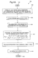
- Fig. 3 sets forth an exemplary DFF control routine 300 for a full order ESC system that operates on a desired roll angle reference model.
- the routine 300 is initiated, at which point control transfers to step 304, where the microprocessor obtains three degree-of-freedom (DOF) vehicle model parameters, such as mass/inertia, tire corner stiffness on a high coefficient of friction surface (high-co), roll stiffness, roll damping, vehicle center of gravity height and roll center height (RCH).
- DOF degree-of-freedom
- step 306 a filtered steering wheel position and vehicle speed are determined.
- a nonlinear vehicle/tire parameter adaptation is performed (e.g., tire cornering stiffness may change as a function of a static desired lateral acceleration A y ), based on the lateral acceleration A y , e.g., calculated from steering angle and speed.
- a desired frequency and damping for a reference model that includes a transfer function having two zeroes and four poles is determined.
- a desired differential brake force is calculated for a transfer function that includes six zeroes and six poles.
- the desired differential brake force is converted to a DVLR command signal, at which point control transfers to step 316, where the routine 300 returns to a calling routine.
- the calling routine then passes the DVLR command signal to an actuator control algorithm which generates brake force commands based on the DVLR command signal.
- a DFF control routine 400 for a full order ESC system utilizing a desired yaw rate reference model is depicted.
- the routine 400 is initiated, at which point control transfers to step 404, where three DOF vehicle model parameters are obtained.
- step 406 a filtered steering wheel position and vehicle speed are obtained.
- step 408 nonlinear vehicle/tire parameter adaptations, based on a static desired lateral acceleration Ay, are initiated.
- step 410 a desired frequency and damping for a reference model having a transfer function with three zeroes and four poles are determined.
- a differential brake force is calculated for a transfer function having seven zeroes and seven poles.
- an appropriate DVLR command signal is determined for the differential brake force, at which point control transfers to step 416, where the routine returns to a calling routine.
- a DFF control routine 420 for a reduced order ESC system utilizing a desired yaw rate reference model is depicted.
- the routine 420 is initiated, at which point control transfers to step 424, where two DOF vehicle model parameters are obtained.
- step 426 a filtered steering wheel position and a vehicle speed are obtained.
- step 428 nonlinear vehicle/tire parameter adaptations, based on a static desired lateral acceleration A y , are performed.
- step 430 a desired frequency and damping for a reference model that includes a transfer function having one zero and two poles is determined.
- step 432 the differential brake force for a transfer function having three zeroes and three poles is calculated.
- step 434 an appropriate DVLR command signal is determined from the differential brake force, at which point control transfers to step 436, where the routine 420 returns to a calling routine.
- Figs. 5A-5D depict graphs of simulation results for a motor vehicle, during a National Highway Traffic Safety Administration (NHTSA) fish-hook maneuver on a dry surface, that illustrate motor vehicle control implemented in an ESC system with DFF control (according to Figs. 4A-4B) and for a base ESC system, for a desired yaw rate reference model.
- ESC based motor vehicle control is activated if the absolute value of the DVLR signal exceeds a preset threshold.
- the threshold may be a function of speed, e.g., greater than 20 KPH, and brake actuation is in the same direction as the DVLR signal.
- a positive DVLR signal indicates a need to generate a clockwise yaw moment, which is achieved by applying one or two brakes on the right side of the vehicle.
- a negative DVLR signal indicates a need to generate a counterclockwise yaw moment, which is achieved by applying one or two brakes on the left side of the vehicle.
- the graph 500 of Fig. 5A depicts curves 502 and 504, which illustrate the brake pressure over time for an ESC system with DFF control and a base ESC system, respectively.
- a graph 510 includes curves 512 and 514, which depict the roll angle as a function of time for an ESC system with DFF control and a base ESC system, respectively.
- Fig. 5C depicts a graph 520 having curves 522 and 524, which depict a yaw rate as a function of time for an ESC system with DFF control and a base ESC system, respectively.
- 5D depicts a graph 530 including curves 532 and 534, which show a tire sideslip angle as a function of time for an ESC system with DFF control and a base ESC system, respectively. As is shown in Figs. 5B and 5D, respectively, the roll angle and tire sideslip angle are reduced for the ESC system with DFF control.
- Figs. 6A-6D correspond to simulation curves for the vehicle utilized to provide the results of Figs. 5A-5D, with the addition of a 200 kilogram payload applied on a top roof of the vehicle.
- a graph 600 includes curves 602 and 604, which illustrate a brake pressure referenced to time for an ESC system with DFF control and a base ESC system, respectively.
- a graph 610 includes curves 612 and 614, which depict a roll angle as a function of time for an ESC system with DFF control and a base ESC system, respectively.
- Fig. 6A-6D correspond to simulation curves for the vehicle utilized to provide the results of Figs. 5A-5D, with the addition of a 200 kilogram payload applied on a top roof of the vehicle.
- a graph 600 includes curves 602 and 604, which illustrate a brake pressure referenced to time for an ESC system with DFF control and a base ESC system, respectively.
- a graph 610 includes curves 612 and 614, which depict
- Fig. 6B an ESC system implementing a dynamic feedforward (DFF) control, according to the present invention, averts excessive roll motion, which would occur with the base ESC model.
- Fig. 6C depicts a graph 620 that includes curves 622 and 624 that plot yaw rate as a function of time for the ESC system with DFF and a base ESC system, respectively.
- Fig. 6D depicts a graph 630 that plots a tire sideslip angle as a function of time and includes curves 632 and 634, which correspond to an ESC system with DFF and a base ESC system, respectively.
- a control system is designed to manage yaw-plane motion, while also comprehending and managing roll motion.
- the control system advantageously accounts for both yaw-plane and roll motion and, thus, avoids coordination problems.
- maneuver-induced roll motion is a function of yaw-plane motion
- Proper shaping of the yaw-plane motion may include increasing yaw damping and/or decreasing a yaw gain, or simply reducing the magnitude of desired yaw rate under various conditions, to avoid excitation of roll dynamics.
- the roll motion is predicted, based upon the severity of steering inputs, and not based upon measured vehicle response provided by a roll rate sensor or lateral acceleration sensor.
- braking is controlled to generate a required yaw moment, via differential braking, to properly shape yaw-plane motion of the vehicle and to limit the roll motion of the vehicle.
- a control system constructed according to this embodiment of the present invention, is based upon a reference model control approach that provides a reference model control structure that may be utilized for both a feedforward configuration and a feedback configuration.
- the reference model generates a desired yaw rate (using steering angle and speed) and may utilize the yaw rate in a feedback loop.
- roll motion prediction logic decides when to dynamically adjust the reference model, to shape the reference model output, i.e., the desired yaw response, to prevent excessive roll motion excitation.
- excessive roll motion may be indicated when a combination of steering angle and steering rate is large for a given speed. It should also be appreciated that other motor vehicle conditions may also be utilized to predict excessive roll motion. In any case, when excessive roll motion is indicated, the desired yaw response is adjusted. The adjustment is made to limit or slow down, e.g., damp, the yaw motion of the vehicle, so as to reduce the roll motion.
- YR des ( 1 ⁇ w ) ⁇ YR desnorm + w ⁇ YR desslow
- w is a weighting constant, which varies from 0 to 1.
- the weight increases when the large roll motion is predicted.
- the normal value of the desired yaw rate can be determined primarily from steering angle and vehicle speed, as has been done in ESC systems and is known to those skilled in the art.
- the slow value of desired yaw rate, YR desslow can be obtained for example by passing the desired normal value, YR desnorm , through a low pass filter with a static gain of 1, or less than 1 if reduction in magnitude of desired yaw rate is required.
- weight w is equal to zero during normal driving, and it increases continuously to 1 when large roll angle is predicted. In general, large roll angle is predicted when the steering angle and steering rate are large for given speed.
- An example calculation of the weigh w is illustrated below.
- a ydPD YR dss ⁇ v x + ⁇ ⁇ d ( YR dss ⁇ v x ) / d t where ⁇ is a positive constant, for example 0.4.
- yaw-plane motion by controlling vehicle yaw-plane motion, excessive maneuver-induced roll motion can be avoided.
- turning the front wheels of a motor vehicle to the right causes lateral forces F yLF , F yRF , F yLR and F yRR to act on the front and rear tires, produces a yaw rate YR and induces a lateral acceleration A y on the vehicle.
- yaw-plane motion is controlled such that excessive maneuver-induced roll motion is avoided.
- Fig. 8 depicts an exemplary feedforward control structure 800 that receives speed and steering inputs 801.
- the inputs 801 are applied to an excessive roll motion prediction model 802, a reference model 804 and a plant model 806.
- the reference model 804 calculates a desired yaw rate and, when excessive roll motion is possible, the desired yaw rate is adjusted to limit and/or slow down, i.e., damp, the vehicle's yaw-plane motion.
- the desired yaw rate is then compared to a predicted yaw rate, provided by the plant model 806, to form an error term, which is provided to an input of a control algorithm 808 that, in response thereto, generates a differential brake force command (Delta Fx), which is provided to a brake subsystem of the vehicle.
- a control algorithm 808 that, in response thereto, generates a differential brake force command (Delta Fx), which is provided to a brake subsystem of the vehicle.
- FIG. 9 another exemplary feedback control structure 900 is depicted that is similar to the structure 800, with the exception that the plant model 806 has been replaced with sensors 910 that provide a measurement or an estimation of an actual yaw rate.
- the actual yaw rate is provided from a sensor instead of being predicted. This modification tends to improve robustness to variations.
- lateral acceleration and its rate of change may be predicted.
- a linear combination of lateral acceleration and its rate of change is used to predict excessive roll motion. When the linear combination is above a threshold, the reference model is gradually modified.
- the rate of change may also be reduced when the linear combination is decreasing in order to prevent jerky control and early exit from the control routine.
- the reference model which is generating the desired yaw rate, is modified by increasing a damping ratio in a dynamic second order filter of the reference model, or reducing the rate of change by other means, or by calculating a desired reduction in yaw rate and subtracting this value from the original desired yaw rate value.
- a graph 1000 is depicted that includes a plurality of desired yaw rates for a motor vehicle in a fishhook maneuver at 45 mph, with a steering angle amplitude of 325 degrees.
- a curve 1002 represents a desired normal yaw rate
- a curve 1004 represents a desired slow yaw rate
- a curve 1006 represents a desired weighted yaw rate
- a curve 1008 represents the weight w multiplied by 10.
- a graph 1020 depicts a plurality of curves 1004A, 1006A and 1008A, for a motor vehicle in a fishhook maneuver at 45 mph, with a steering angle amplitude of 110 degrees.
- the curve 1004A corresponds to a desired slow yaw rate
- the curve 1006A corresponds to a desired weighted yaw rate, which is identical to the desired normal yaw rate
- the curve 1008A corresponds to the weight w multiplied by 10, which is zero throughout the maneuver. It is seen that in the less severe maneuver, the algorithm does not change the desired yaw rate, which remains identical to the normal desired yaw rate.
- Figs. 11A-11D correspond to test data for a motor vehicle in a fishhook maneuver at 65 KPH without feedforward control.
- Fig. 11A depicts a graph 1100 having a curve 1102 that plots a lateral position of the motor vehicle as a function of the longitudinal position, in the performance of a fishhook maneuver.
- Fig. 11B is a graph 1110 that includes a curve 1112 that shows the position of the steering angle as a function of time.
- Fig. 11C is a graph 1120 that includes a curve 1122 that shows a motor vehicle brake pressure as a function of time.
- Fig. 11D is a graph 1130 that includes a plurality of curves 1132, 1134, 1136 and 1138, which depict roll angle, tire sideslip, yaw rate/5 and lateral acceleration of the motor vehicle, respectively, as a function of time.
- Figs. 12A-12D correspond to test data for a motor vehicle in a fishhook maneuver at 65 KPH with feedforward control, according to Fig. 8.
- Fig. 12A depicts a graph 1200 having a curve 1202 that plots a lateral position of the motor vehicle as a function of the longitudinal position, in the performance of a fishhook maneuver.
- Fig. 12B is a graph 1210 that includes a curve 1212 that shows the position of the steering angle as a function of time.
- Fig. 12C is a graph 1220 that includes curves 1222 and 1224 that shows the motor vehicle brake pressure for the right and left front wheels, respectively, as a function of time.
- Fig. 12A depicts a graph 1200 having a curve 1202 that plots a lateral position of the motor vehicle as a function of the longitudinal position, in the performance of a fishhook maneuver.
- Fig. 12B is a graph 1210 that includes a curve 1212 that shows the position of the steering angle as a function of
- FIG. 12D is a graph 1230 that includes a plurality of curves 1232, 1234, 1236 and 1238, which depict roll angle, tire sideslip, yaw rate/5 and lateral acceleration of the motor vehicle, respectively, as a function of time. Contrasting Fig. 11D to Fig. 12D, it is apparent that the control structure 800 of Fig. 8 has controlled the motor vehicle to cause a reduction in the roll angle of the motor vehicle.
- Figs. 13A-13D correspond to test data for a motor vehicle in a fishhook maneuver with feedforward control, configured according to the control structure 900 of Fig. 9.
- Fig. 13A depicts a graph 1300 having a curve 1302 that plots a lateral position of the motor vehicle as a function of the longitudinal position, in the performance of a fishhook maneuver.
- Fig. 13B is a graph 1310 that includes a curve 1312 that shows the position of the steering angle as a function of time.
- Fig. 13C is a graph 1320 that includes curves 1322 and 1324 that show the motor vehicle brake pressure for the right and left front wheels, respectively, as a function of time.
- Fig. 13A depicts a graph 1300 having a curve 1302 that plots a lateral position of the motor vehicle as a function of the longitudinal position, in the performance of a fishhook maneuver.
- Fig. 13B is a graph 1310 that includes a curve 1312 that shows the position of the steering angle as
- 13D is a graph 1330 that includes a plurality of curves 1332, 1334, 1336 and 1338, which depict roll angle, tire sideslip, yaw rate/5 and lateral acceleration of the motor vehicle, respectively, as a function of time.
- implementation of the control structure 900 results in a roll angle reduction.
- feedforward control structures have been described herein that advantageously manage both yaw-plane and roll motion of a motor vehicle.
Landscapes
- Engineering & Computer Science (AREA)
- Transportation (AREA)
- Mechanical Engineering (AREA)
- Regulating Braking Force (AREA)
- Control Of Driving Devices And Active Controlling Of Vehicle (AREA)
- Steering Control In Accordance With Driving Conditions (AREA)
Priority Applications (1)
| Application Number | Priority Date | Filing Date | Title |
|---|---|---|---|
| EP07075420A EP1837262A1 (de) | 2004-09-27 | 2005-09-19 | Kraftfahrzeugsteuerung über einen dynamischen Vorwärtsansatz |
Applications Claiming Priority (2)
| Application Number | Priority Date | Filing Date | Title |
|---|---|---|---|
| US61354304P | 2004-09-27 | 2004-09-27 | |
| US11/019,145 US7191047B2 (en) | 2004-09-27 | 2004-12-21 | Motor vehicle control using a dynamic feedforward approach |
Related Child Applications (1)
| Application Number | Title | Priority Date | Filing Date |
|---|---|---|---|
| EP07075420A Division EP1837262A1 (de) | 2004-09-27 | 2005-09-19 | Kraftfahrzeugsteuerung über einen dynamischen Vorwärtsansatz |
Publications (1)
| Publication Number | Publication Date |
|---|---|
| EP1640231A1 true EP1640231A1 (de) | 2006-03-29 |
Family
ID=35500598
Family Applications (1)
| Application Number | Title | Priority Date | Filing Date |
|---|---|---|---|
| EP05077122A Withdrawn EP1640231A1 (de) | 2004-09-27 | 2005-09-19 | Fahrdynamikregelung mit Vorwärtssteurung |
Country Status (2)
| Country | Link |
|---|---|
| US (1) | US7191047B2 (de) |
| EP (1) | EP1640231A1 (de) |
Cited By (3)
| Publication number | Priority date | Publication date | Assignee | Title |
|---|---|---|---|---|
| EP1930222A1 (de) * | 2006-12-08 | 2008-06-11 | Delphi Technologies, Inc. | Verfahren zur Ermöglichung der Stabilitätskontrolle eines Fahrzeugs |
| EP2019916A2 (de) * | 2006-05-12 | 2009-02-04 | Delphi Technologies, Inc. | System und verfahren zur steuerung des hydrauliksystems eines fahrzeugs |
| EP2055600B1 (de) * | 2007-10-29 | 2013-01-16 | Hitachi Ltd. | Fahrzeugsteuervorrichtung |
Families Citing this family (24)
| Publication number | Priority date | Publication date | Assignee | Title |
|---|---|---|---|---|
| JP3868848B2 (ja) * | 2002-05-23 | 2007-01-17 | 三菱電機株式会社 | 車両状態検出装置 |
| JP4293431B2 (ja) * | 2003-06-11 | 2009-07-08 | 富士重工業株式会社 | 車両制御装置および車両制御方法 |
| KR20070116819A (ko) * | 2005-02-22 | 2007-12-11 | 켈시-헤이즈 컴파니 | 정적 타이어 데이터를 이용하는 차량 안정성 제어 시스템및 방법 |
| JP4835189B2 (ja) * | 2006-02-16 | 2011-12-14 | 日産自動車株式会社 | 旋回挙動制御装置、自動車、及び旋回挙動制御方法 |
| US8135528B2 (en) * | 2006-06-30 | 2012-03-13 | Honda Motor Co., Ltd. | Vehicle control device |
| US7970512B2 (en) * | 2006-08-30 | 2011-06-28 | Ford Global Technologies | Integrated control system for stability control of yaw, roll and lateral motion of a driving vehicle using an integrated sensing system with pitch information |
| KR100828778B1 (ko) * | 2006-11-29 | 2008-05-09 | 현대자동차주식회사 | 차량의 질량 추정 방법 |
| JP4586795B2 (ja) * | 2006-12-07 | 2010-11-24 | トヨタ自動車株式会社 | 車両用制御装置 |
| FR2916180B1 (fr) * | 2007-05-14 | 2009-07-03 | Renault Sas | Procede et dispositif de gestion d'une consigne de braquage appliquee a au moins un actionneur de braquage des roues arriere d'un vehicule automobile |
| US8744689B2 (en) * | 2007-07-26 | 2014-06-03 | Hitachi, Ltd. | Drive controlling apparatus for a vehicle |
| JP5031482B2 (ja) * | 2007-08-10 | 2012-09-19 | 株式会社デンソー | 車両用停止制御装置及び制御システム |
| DE102009000922A1 (de) * | 2009-02-17 | 2010-08-19 | Robert Bosch Gmbh | Verfahren zur Fahrzeugstabilisierung mit integrierter Funktion zur Umkippvermeidung |
| DE102010004113B4 (de) * | 2010-01-07 | 2014-11-20 | Continental Automotive Gmbh | Verfahren und Vorrichtung zur Ermittlung eines maximalen Reibungsbeiwerts μmax zwischen einem Reifen und einem Untergrund |
| US8666626B2 (en) * | 2010-03-04 | 2014-03-04 | Honda Motor Co., Ltd. | Turning control device for vehicle |
| CN102753409B (zh) | 2010-03-04 | 2015-05-06 | 本田技研工业株式会社 | 车辆的转弯控制装置 |
| US9096201B2 (en) | 2011-03-18 | 2015-08-04 | Robert Bosch Gmbh | Yaw rate forecasting |
| US9283825B2 (en) | 2014-02-25 | 2016-03-15 | Isam Mousa | System, method, and apparatus to prevent commercial vehicle rollover |
| US10723380B2 (en) * | 2017-02-24 | 2020-07-28 | Ford Global Technologies, Llc | Systems and methods to control steering of a vehicle |
| SE541786C2 (en) * | 2017-08-28 | 2019-12-17 | Scania Cv Ab | A method for providing vehicle steering support by differential wheel braking, a system, a vehicle, a computer program and a computer-readable medium. |
| US10759416B1 (en) | 2017-10-18 | 2020-09-01 | Zoox, Inc. | Independent control of vehicle wheels |
| US10821981B1 (en) | 2017-10-18 | 2020-11-03 | Zoox, Inc. | Independent control of vehicle wheels |
| US11136021B1 (en) * | 2017-10-18 | 2021-10-05 | Zoox, Inc. | Independent control of vehicle wheels |
| US10488172B1 (en) | 2017-10-18 | 2019-11-26 | Zoox, Inc. | Independent control of vehicle wheels |
| US10850586B2 (en) | 2018-08-23 | 2020-12-01 | Tenneco Automotive Operating Company Inc. | Anti-roll moment distribution active suspension |
Citations (6)
| Publication number | Priority date | Publication date | Assignee | Title |
|---|---|---|---|---|
| US6056371A (en) * | 1998-08-24 | 2000-05-02 | General Motors Corporation | Feed-forward active brake control |
| US20020059023A1 (en) * | 2000-10-05 | 2002-05-16 | Toyota Jidosha Kabushiki Kaisha | Rolling control apparatus and method of vehicle |
| DE10130663A1 (de) * | 2001-06-28 | 2003-01-23 | Continental Teves Ag & Co Ohg | Verfahren zum Modifizieren einer Fahrstabilitätsregelung eines Fahrzeugs |
| DE10135020A1 (de) * | 2001-07-18 | 2003-02-13 | Bosch Gmbh Robert | Verfahren und Vorrichtung zur Erkennung und Behebung einer Umkippgefahr |
| EP1285833A2 (de) * | 2001-08-22 | 2003-02-26 | Delphi Technologies, Inc. | Verfahren und Vorrichtung mit dynamischer Vorwärtssteuerung zur integrierten Lenk- und Bremssteuerung eines Kraftfahrzeugs |
| US20040117085A1 (en) * | 2001-11-21 | 2004-06-17 | Jianbo Lu | Enhanced system for yaw stability control system to include roll stability control function |
Family Cites Families (131)
| Publication number | Priority date | Publication date | Assignee | Title |
|---|---|---|---|---|
| GB1561650A (en) * | 1976-01-29 | 1980-02-27 | Sperry Rand Corp | Aircraft control system |
| FR2498315B1 (fr) * | 1981-01-20 | 1986-04-04 | Muller & Cie Ets M | Procede pour mesurer le parallelisme des ro ues des trains avant et arriere de vehicules automobiles ainsi que les angles de set-back entre les roues du train avant et l'angle de crabe, et appareillage pour la mise en oeuvre de ce procede |
| JPH0674052B2 (ja) * | 1984-01-31 | 1994-09-21 | 日産自動車株式会社 | 車両の操舵方法 |
| US4767588A (en) | 1985-04-13 | 1988-08-30 | Nissan Motor Co., Ltd. | Vehicle control system for controlling side slip angle and yaw rate gain |
| US4723444A (en) * | 1986-09-17 | 1988-02-09 | Jaroslav Hajek | Apparatus for determining side-slip characteristics of a moving vehicle |
| JPH0725320B2 (ja) * | 1986-10-13 | 1995-03-22 | 日産自動車株式会社 | 車両用実舵角制御装置 |
| JPH0750121B2 (ja) | 1988-04-19 | 1995-05-31 | 日産自動車株式会社 | 車両スリップ角測定装置 |
| US4842089A (en) * | 1988-06-27 | 1989-06-27 | General Motors Corporation | Four wheel steering system with closed-loop feedback and open-loop feedforward |
| EP0364965B1 (de) | 1988-10-18 | 1993-08-18 | Nissan Motor Co., Ltd. | Aktive Radaufhängung für ein Kraftfahrzeug mit Driftwinkel-abhängiger Steuerung zur Verbesserung des Lenkverhaltens |
| JP2844240B2 (ja) | 1990-03-15 | 1999-01-06 | 本田技研工業株式会社 | 自動走行装置 |
| JP2762711B2 (ja) | 1990-07-02 | 1998-06-04 | 日産自動車株式会社 | 車両の制動挙動補償装置 |
| JP3098124B2 (ja) * | 1992-11-05 | 2000-10-16 | 本田技研工業株式会社 | 後輪転舵装置の制御方法 |
| JP3091038B2 (ja) | 1992-12-02 | 2000-09-25 | 本田技研工業株式会社 | 前後輪操舵車両の制御装置 |
| DE4243717A1 (de) * | 1992-12-23 | 1994-06-30 | Bosch Gmbh Robert | Verfahren zur Regelung der Fahrzeugstabilität |
| JP3150832B2 (ja) * | 1993-10-26 | 2001-03-26 | トヨタ自動車株式会社 | 車両用制動制御装置 |
| JP2882232B2 (ja) | 1993-03-17 | 1999-04-12 | 三菱自動車工業株式会社 | 車体重心スリップ角計測装置 |
| JP2982595B2 (ja) * | 1993-12-27 | 1999-11-22 | 日産自動車株式会社 | 車両用実舵角制御装置 |
| US5710705A (en) * | 1994-11-25 | 1998-01-20 | Itt Automotive Europe Gmbh | Method for determining an additional yawing moment based on side slip angle velocity |
| DE19549800B4 (de) * | 1994-11-25 | 2017-03-09 | Continental Teves Ag & Co. Ohg | Fahrstabilitätseinrichtung für ein Fahrzeug |
| JP3189610B2 (ja) * | 1995-02-20 | 2001-07-16 | トヨタ自動車株式会社 | 車両挙動制御装置 |
| US6128076A (en) | 1995-04-19 | 2000-10-03 | Sackett; Robert | Apparatus for measuring truck tilt and preventing roll-over |
| US5684700A (en) | 1995-12-05 | 1997-11-04 | Ford Global Technologies, Inc. | Adaptive steering control using vehicle slip angle and steering rate |
| US5899952A (en) * | 1995-12-27 | 1999-05-04 | Toyota Jidosha Kabushiki Kaisha | Device for estimating slip angle of vehicle body through interrelation thereof with yaw rate |
| DE19602879C1 (de) * | 1996-01-29 | 1997-08-07 | Knorr Bremse Systeme | Verfahren zum Erfassen der Gefahr des Umkippens eines Fahrzeuges |
| DE69618337T2 (de) * | 1996-02-27 | 2003-02-13 | Knorr-Bremse Systeme Fuer Nutzfahrzeuge Gmbh | Verfahren zur Fahrstabilitätserhöhung |
| DE19609717A1 (de) * | 1996-03-13 | 1997-09-18 | Bosch Gmbh Robert | Anordnung zum Erkennen von Überrollvorgängen bei Fahrzeugen |
| JPH09269804A (ja) * | 1996-03-29 | 1997-10-14 | Aisin Seiki Co Ltd | 自動制御系の安定制御装置 |
| JPH09301142A (ja) * | 1996-05-10 | 1997-11-25 | Aisin Seiki Co Ltd | 車両の制動力制御装置 |
| US6059067A (en) * | 1996-05-22 | 2000-05-09 | Honda Giken Kogyo Kabushiki Kaisha | Yaw moment control process and apparatus for a vehicle |
| JPH10119743A (ja) * | 1996-10-23 | 1998-05-12 | Aisin Seiki Co Ltd | 車両の運動制御装置 |
| US5825284A (en) | 1996-12-10 | 1998-10-20 | Rollover Operations, Llc | System and method for the detection of vehicle rollover conditions |
| US6202488B1 (en) * | 1996-12-13 | 2001-03-20 | Trw Inc. | Vehicle rollover sensor |
| JPH10267685A (ja) | 1997-03-21 | 1998-10-09 | Unisia Jecs Corp | 車両の横滑り角推定方法 |
| JP3269421B2 (ja) * | 1997-04-04 | 2002-03-25 | 三菱自動車工業株式会社 | 車両の自動減速制御装置 |
| US6065558A (en) * | 1997-07-01 | 2000-05-23 | Dynamotive, L.L.C. | Anti-rollover brake system |
| JP4129702B2 (ja) * | 1997-07-11 | 2008-08-06 | マツダ株式会社 | 車両の姿勢制御装置 |
| JP3198993B2 (ja) * | 1997-07-23 | 2001-08-13 | トヨタ自動車株式会社 | 車輌の挙動制御装置 |
| JP3937524B2 (ja) * | 1997-09-30 | 2007-06-27 | トヨタ自動車株式会社 | 車輌の制駆動力制御装置 |
| US6233513B1 (en) * | 1997-11-27 | 2001-05-15 | Masato Abe | Method and system for computing a vehicle body slip angle in a vehicle movement control |
| DE19802041A1 (de) * | 1998-01-21 | 1999-07-22 | Bosch Gmbh Robert | Verfahren und Vorrichtung zur Stabilisierung eines Fahrzeuges im Sinne einer Umkippvermeidung |
| US6002975A (en) | 1998-02-06 | 1999-12-14 | Delco Electronics Corporation | Vehicle rollover sensing |
| US6002974A (en) * | 1998-02-06 | 1999-12-14 | Delco Electronics Corporation | Vehicle rollover sensing using extended kalman filter |
| US6038495A (en) * | 1998-02-06 | 2000-03-14 | Delco Electronics Corporation | Vehicle rollover sensing using short-term integration |
| JP3855441B2 (ja) | 1998-03-06 | 2006-12-13 | トヨタ自動車株式会社 | 車体ロール評価値演算装置 |
| US5955714A (en) | 1998-05-20 | 1999-09-21 | Breed Technologies, Inc. | Roll-over shunt sensor |
| JP4828698B2 (ja) | 1998-06-22 | 2011-11-30 | コンティネンタル・テーベス・アクチエンゲゼルシヤフト・ウント・コンパニー・オッフェネ・ハンデルスゲゼルシヤフト | 車両の走行安定性を制御する制御回路 |
| DE19827881A1 (de) | 1998-06-23 | 1999-12-30 | Bosch Gmbh Robert | Verfahren und Vorrichtung zur Stabilisierung eines Fahrzeugs |
| DE19827882A1 (de) * | 1998-06-23 | 1999-12-30 | Bosch Gmbh Robert | Verfahren und Vorrichtung zur Stabilisierung eines Fahrzeugs |
| JP3669668B2 (ja) * | 1998-07-10 | 2005-07-13 | 本田技研工業株式会社 | 車両用車輪スリップ角検出装置 |
| JP2002520604A (ja) | 1998-07-16 | 2002-07-09 | コンティネンタル・テーベス・アクチエンゲゼルシヤフト・ウント・コンパニー・オッフェネ・ハンデルスゲゼルシヤフト | 自動車のロールオーバーの危険を検出する方法と装置 |
| EP1097069B1 (de) | 1998-07-17 | 2002-07-31 | Continental Teves AG & Co. oHG | Verfahren und vorrichtung zum bestimmen und erkennen der kippgefahr eines fahrzeuges |
| JP3695164B2 (ja) * | 1998-08-03 | 2005-09-14 | トヨタ自動車株式会社 | 車輌の挙動制御方法 |
| US6225894B1 (en) * | 1998-09-24 | 2001-05-01 | Meritor Heavy Vehicle Systems, Llc | Roll-over detector for vehicles |
| DE19844540A1 (de) | 1998-09-29 | 2000-03-30 | Bosch Gmbh Robert | Anordnungen und Verfahren zur Vermeidung von Überschlägen bei Bremsvorgängen oder Beschleunigungsvorgängen für Kraftfahrzeuge |
| US6179394B1 (en) * | 1998-11-09 | 2001-01-30 | General Motors Corporation | Active brake balance control method |
| US6292759B1 (en) | 1998-11-19 | 2001-09-18 | Delphi Technologies, Inc. | Vehicle attitude angle estimation using sensed signal blending |
| US6678631B2 (en) * | 1998-11-19 | 2004-01-13 | Delphi Technologies, Inc. | Vehicle attitude angle estimator and method |
| US6161905A (en) | 1998-11-19 | 2000-12-19 | General Motors Corporation | Active brake control including estimation of yaw rate and slip angle |
| DE19859966A1 (de) | 1998-12-29 | 2000-07-13 | Bosch Gmbh Robert | Vorrichtung und Verfahren zur Stabilisierung eines Fahrzeuges |
| JP4468509B2 (ja) * | 1999-04-06 | 2010-05-26 | 本田技研工業株式会社 | 車両用操舵装置 |
| US6397133B1 (en) * | 1999-04-19 | 2002-05-28 | Palmer Safety Systems, Llc | Vehicle rollover safety system |
| JP3726557B2 (ja) | 1999-05-26 | 2005-12-14 | トヨタ自動車株式会社 | 車輌のロール抑制制御装置 |
| US6304805B1 (en) | 1999-07-21 | 2001-10-16 | Denso Corporation | Vehicle behavior estimating and controlling method and system as well as body slip angle estimating method and system |
| US6216536B1 (en) * | 1999-07-26 | 2001-04-17 | Karl J. Manseth | Sideslip indicator for a snow ski |
| US6301536B1 (en) | 1999-11-18 | 2001-10-09 | Visteon Global Technologies, Inc. | Method and apparatus for detecting a vehicle rollover |
| US6681167B2 (en) * | 1999-12-15 | 2004-01-20 | Delphi Technologies, Inc. | Vehicle chassis control with coordinated brake and steering control on split coefficient surface |
| US6324446B1 (en) | 1999-12-21 | 2001-11-27 | Ford Global Technologies, Inc. | Roll over stability control for an automotive vehicle |
| US6263261B1 (en) | 1999-12-21 | 2001-07-17 | Ford Global Technologies, Inc. | Roll over stability control for an automotive vehicle |
| US6332104B1 (en) | 1999-12-21 | 2001-12-18 | Ford Global Technologies, Inc. | Roll over detection for an automotive vehicle |
| DE10000535C2 (de) * | 2000-01-08 | 2003-06-26 | Bayerische Motoren Werke Ag | Verfahren zur Kalibrierung eines Überrollsensors |
| EP1125826A3 (de) * | 2000-02-11 | 2003-01-08 | Delphi Technologies, Inc. | Steuerung unabhängiger Lenkaktuatoren zur Verbesserung von Fahrzeugstabilität und Bremsverhalten |
| US6415215B1 (en) | 2000-02-23 | 2002-07-02 | Koyo Seiko Co., Ltd. | Vehicle attitude control apparatus |
| US6505108B2 (en) * | 2000-03-01 | 2003-01-07 | Delphi Technologies, Inc. | Damper based vehicle yaw control |
| DE10010633A1 (de) * | 2000-03-03 | 2001-09-06 | Siemens Ag | Verfahren zum Erkennen einer Rollover-Situation |
| US6507016B1 (en) * | 2000-04-18 | 2003-01-14 | Trw Inc. | Apparatus and method for sensing a vehicle rollover condition |
| DE10019416A1 (de) * | 2000-04-19 | 2001-10-25 | Bosch Gmbh Robert | Anordnung zur Plausibilisierung einer Überrollentscheidung |
| DE10025259C2 (de) * | 2000-05-22 | 2003-03-20 | Conti Temic Microelectronic | Verfahren zur Erzeugung eines Auslösealgorithmus zur Erkennung eines Überschlages für ein Sicherheitssystem in einem Kraftfahrzeug |
| DE10025260B4 (de) | 2000-05-22 | 2004-11-25 | Conti Temic Microelectronic Gmbh | Verfahren zur Detektion von Überrollvorgängen bei Kraftfahrzeugen mit Sicherheitseinrichtungen |
| US6282474B1 (en) | 2000-06-04 | 2001-08-28 | Ford Global Technologies, Inc. | Method and apparatus for detecting rollover of an automotive vehicle |
| US6356188B1 (en) * | 2000-09-25 | 2002-03-12 | Ford Global Technologies, Inc. | Wheel lift identification for an automotive vehicle |
| US6397127B1 (en) * | 2000-09-25 | 2002-05-28 | Ford Global Technologies, Inc. | Steering actuated wheel lift identification for an automotive vehicle |
| US7109856B2 (en) * | 2000-09-25 | 2006-09-19 | Ford Global Technologies, Llc | Wheel lifted and grounded identification for an automotive vehicle |
| JP2002127887A (ja) | 2000-10-24 | 2002-05-09 | Sumitomo Electric Ind Ltd | 車両の姿勢制御装置 |
| DE10054647A1 (de) * | 2000-11-03 | 2002-05-08 | Daimler Chrysler Ag | Verfahren zur Regelung der Fahrstabilität |
| US6584388B2 (en) * | 2001-11-08 | 2003-06-24 | Delphi Technologies, Inc. | Adaptive rollover detection apparatus and method |
| US6542792B2 (en) * | 2000-11-29 | 2003-04-01 | Delphi Technologies, Inc. | Vehicle rollover detection apparatus and method |
| US6542073B2 (en) * | 2000-12-20 | 2003-04-01 | Trw Inc. | System and method for sensing vehicle rollover |
| US6600414B2 (en) | 2000-12-20 | 2003-07-29 | Trw Inc. | Apparatus and method for detecting vehicle rollover having a discriminating safing function |
| DE10065010A1 (de) * | 2000-12-23 | 2002-07-04 | Bosch Gmbh Robert | Verfahren und Vorrichtung zum Stabilisieren eines Fahrzeugs |
| US6453226B1 (en) * | 2001-01-25 | 2002-09-17 | Delphi Technologies, Inc. | Integrated control of active tire steer and brakes |
| EP1236620B1 (de) * | 2001-03-01 | 2007-01-24 | Automotive Systems Laboratory Inc. | Überrolldetektionssystem für Kraftfahrzeuge |
| US6954140B2 (en) * | 2001-03-16 | 2005-10-11 | Bendix Commercial Vehicle Systems Llc | Method and apparatus for vehicle rollover prediction and prevention |
| DE10122654A1 (de) * | 2001-05-10 | 2002-12-05 | Bosch Gmbh Robert | Verfahren und System zur Regelung des Fahrverhaltens eines Fahrzeugs |
| US7140619B2 (en) * | 2001-05-24 | 2006-11-28 | Ford Global Technologies, Llc | Roll over stability control for an automotive vehicle having an active suspension |
| US6535800B2 (en) * | 2001-05-29 | 2003-03-18 | Delphi Technologies, Inc. | Vehicle rollover sensing using angular rate sensors |
| US6560519B2 (en) * | 2001-06-28 | 2003-05-06 | Robert Bosch Corporation | Rollover-sensing system for a vehicle and method of operating the same |
| US6829524B2 (en) * | 2001-08-20 | 2004-12-07 | Wisys Technology Foundation, Inc. | Method and apparatus for estimating yaw rate in a wheeled vehicle and stability system |
| US6567731B2 (en) * | 2001-08-22 | 2003-05-20 | Delphi Technologies, Inc. | System and method incorporating feedforward for motor vehicle chassis control |
| US6546324B1 (en) * | 2001-08-22 | 2003-04-08 | Delphi Technologies, Inc. | System and method incorporating dynamic feedforward for integrated control of motor vehicle steering and braking |
| DE10141274A1 (de) * | 2001-08-23 | 2003-03-27 | Bayerische Motoren Werke Ag | Kraftfahrzeug-Lenksystem mit einem Gierratenregler |
| US7107136B2 (en) * | 2001-08-29 | 2006-09-12 | Delphi Technologies, Inc. | Vehicle rollover detection and mitigation using rollover index |
| US6725135B2 (en) * | 2001-09-26 | 2004-04-20 | Stability Dynamics | Vehicle stability operator feedback system |
| US6631317B2 (en) | 2001-10-01 | 2003-10-07 | Ford Global Technologies, Inc. | Attitude sensing system for an automotive vehicle |
| US6735510B2 (en) * | 2001-10-12 | 2004-05-11 | Delphi Technologies, Inc. | Dynamic side to side brake proportioning |
| DE10161851A1 (de) * | 2001-12-15 | 2003-06-26 | Daimler Chrysler Ag | Kühlkreislauf einer flüssigkeitsgekühlten Brennkraftmaschine |
| US6704622B2 (en) * | 2001-12-28 | 2004-03-09 | Visteon Global Technologies, Inc. | Vehicle stability control |
| US6553293B1 (en) * | 2002-01-03 | 2003-04-22 | Delphi Technologies, Inc. | Rear steering control for vehicles with front and rear steering |
| US6714851B2 (en) * | 2002-01-07 | 2004-03-30 | Ford Global Technologies, Llc | Method for road grade/vehicle pitch estimation |
| US6671595B2 (en) | 2002-01-08 | 2003-12-30 | Ford Global Technologies, Llc | Vehicle side slip angle estimation using dynamic blending and considering vehicle attitude information |
| US6518751B1 (en) * | 2002-02-05 | 2003-02-11 | Ford Global Technologies, Inc. | Magnetoresistive rollover sensor |
| US6654671B2 (en) | 2002-02-15 | 2003-11-25 | Delphi Technologies, Inc. | Vehicle rollover detection having variable sensitivity |
| US6556908B1 (en) * | 2002-03-04 | 2003-04-29 | Ford Global Technologies, Inc. | Attitude sensing system for an automotive vehicle relative to the road |
| JP3963217B2 (ja) * | 2002-04-30 | 2007-08-22 | 株式会社日立製作所 | 車両横転防止装置 |
| US6741922B2 (en) * | 2002-05-30 | 2004-05-25 | Bendix Commercial Vehicle Systems Llc | Antilock braking system based roll over prevention |
| US6718248B2 (en) * | 2002-06-19 | 2004-04-06 | Ford Global Technologies, Llc | System for detecting surface profile of a driving road |
| US6672689B1 (en) * | 2002-06-28 | 2004-01-06 | Continental Teves, Inc. | System and method of regulating manual control of a vehicle in a sliding condition |
| US7085639B2 (en) * | 2002-08-01 | 2006-08-01 | Ford Global Technologies, Llc | System and method for characterizing the road bank for vehicle roll stability control |
| US7003389B2 (en) * | 2002-08-01 | 2006-02-21 | Ford Global Technologies, Llc | System and method for characterizing vehicle body to road angle for vehicle roll stability control |
| US7194351B2 (en) * | 2002-08-01 | 2007-03-20 | Ford Global Technologies, Llc | System and method for determining a wheel departure angle for a rollover control system |
| US7302331B2 (en) * | 2002-08-01 | 2007-11-27 | Ford Global Technologies, Inc. | Wheel lift identification for an automotive vehicle |
| US7430468B2 (en) * | 2002-08-05 | 2008-09-30 | Ford Global Technologies, Llc | System and method for sensitizing the activation criteria of a rollover control system |
| US6963797B2 (en) * | 2002-08-05 | 2005-11-08 | Ford Global Technologies, Llc | System and method for determining an amount of control for operating a rollover control system |
| US20040024505A1 (en) * | 2002-08-05 | 2004-02-05 | Salib Albert Chenouda | System and method for operating a rollover control system in a transition to a rollover condition |
| US20040024504A1 (en) * | 2002-08-05 | 2004-02-05 | Salib Albert Chenouda | System and method for operating a rollover control system during an elevated condition |
| US7143864B2 (en) * | 2002-09-27 | 2006-12-05 | Ford Global Technologies, Llc. | Yaw control for an automotive vehicle using steering actuators |
| US6728621B1 (en) * | 2002-10-04 | 2004-04-27 | General Motors Corporation | Anti-lock braking system controller for adjusting slip thresholds on inclines |
| US6662898B1 (en) | 2002-10-16 | 2003-12-16 | Ford Global Technologies, Llc | Tire side slip angle control for an automotive vehicle using steering actuators |
| US6840343B2 (en) * | 2002-10-16 | 2005-01-11 | Ford Global Technologies, Llc | Tire side slip angle control for an automotive vehicle using steering peak seeking actuators |
| US6865468B2 (en) * | 2002-11-26 | 2005-03-08 | General Motors Corporation | Method and apparatus for vehicle stability enhancement system |
| US6819998B2 (en) * | 2002-11-26 | 2004-11-16 | General Motors Corporation | Method and apparatus for vehicle stability enhancement system |
| US7502675B2 (en) * | 2004-04-01 | 2009-03-10 | Delphi Technologies, Inc. | Feedforward control of motor vehicle roll angle |
-
2004
- 2004-12-21 US US11/019,145 patent/US7191047B2/en active Active
-
2005
- 2005-09-19 EP EP05077122A patent/EP1640231A1/de not_active Withdrawn
Patent Citations (6)
| Publication number | Priority date | Publication date | Assignee | Title |
|---|---|---|---|---|
| US6056371A (en) * | 1998-08-24 | 2000-05-02 | General Motors Corporation | Feed-forward active brake control |
| US20020059023A1 (en) * | 2000-10-05 | 2002-05-16 | Toyota Jidosha Kabushiki Kaisha | Rolling control apparatus and method of vehicle |
| DE10130663A1 (de) * | 2001-06-28 | 2003-01-23 | Continental Teves Ag & Co Ohg | Verfahren zum Modifizieren einer Fahrstabilitätsregelung eines Fahrzeugs |
| DE10135020A1 (de) * | 2001-07-18 | 2003-02-13 | Bosch Gmbh Robert | Verfahren und Vorrichtung zur Erkennung und Behebung einer Umkippgefahr |
| EP1285833A2 (de) * | 2001-08-22 | 2003-02-26 | Delphi Technologies, Inc. | Verfahren und Vorrichtung mit dynamischer Vorwärtssteuerung zur integrierten Lenk- und Bremssteuerung eines Kraftfahrzeugs |
| US20040117085A1 (en) * | 2001-11-21 | 2004-06-17 | Jianbo Lu | Enhanced system for yaw stability control system to include roll stability control function |
Cited By (4)
| Publication number | Priority date | Publication date | Assignee | Title |
|---|---|---|---|---|
| EP2019916A2 (de) * | 2006-05-12 | 2009-02-04 | Delphi Technologies, Inc. | System und verfahren zur steuerung des hydrauliksystems eines fahrzeugs |
| EP2019916A4 (de) * | 2006-05-12 | 2013-08-07 | Bwi Co Ltd Sa | System und verfahren zur steuerung des hydrauliksystems eines fahrzeugs |
| EP1930222A1 (de) * | 2006-12-08 | 2008-06-11 | Delphi Technologies, Inc. | Verfahren zur Ermöglichung der Stabilitätskontrolle eines Fahrzeugs |
| EP2055600B1 (de) * | 2007-10-29 | 2013-01-16 | Hitachi Ltd. | Fahrzeugsteuervorrichtung |
Also Published As
| Publication number | Publication date |
|---|---|
| US7191047B2 (en) | 2007-03-13 |
| US20060069489A1 (en) | 2006-03-30 |
Similar Documents
| Publication | Publication Date | Title |
|---|---|---|
| EP1640231A1 (de) | Fahrdynamikregelung mit Vorwärtssteurung | |
| EP1495931B1 (de) | Vorrichtung zur Regelung des Fahrverhaltens eines Fahrzeugs | |
| EP1234741B2 (de) | Überrollstabilitätssteuerung für ein Kraftfahrzeug | |
| US8718872B2 (en) | Vehicle attitude controller | |
| US7330785B2 (en) | Method for increasing the driving stability of a motor vehicle | |
| CN111267835B (zh) | 基于模型预测算法的四轮独立驱动汽车稳定性控制方法 | |
| US20060158031A1 (en) | Method and system for controlling the driving stability of a vehicle and use of said system | |
| US6112147A (en) | Vehicle yaw rate control with bank angle compensation | |
| US6591179B1 (en) | Method and system for progressive engagement of all-wheel drive | |
| JP2002114140A (ja) | 車輌のロール挙動制御装置 | |
| JP4747722B2 (ja) | 車両の横転防止装置 | |
| EP1419951A2 (de) | Verfahren und Vorrichtung für Fahrzeug-Stabilitätsverbesserungs-Systeme | |
| US7668637B2 (en) | Technique for determining motor vehicle slip angle while accounting for road banks | |
| JP2002087310A (ja) | 横方向力の測定に基づいた車両軌道へのアクション | |
| US7502675B2 (en) | Feedforward control of motor vehicle roll angle | |
| JP2003231429A (ja) | 車両の中心対称面の両側での荷重移動を考慮した横方向力の測定値による車両の軌道へのアクション | |
| EP2289746B1 (de) | System zur Verbesserung der Kurvenfahrtleistung eines Fahrzeugs, das von einem Sicherheitssystem gesteuert wird | |
| US7493201B2 (en) | Method and apparatus for controlling active front steering | |
| JP3748334B2 (ja) | 車両の姿勢制御装置 | |
| EP1695894B1 (de) | Methode und Vorrichtung zur Gierratenkontrolle eines Fahrzeugs | |
| EP1837262A1 (de) | Kraftfahrzeugsteuerung über einen dynamischen Vorwärtsansatz | |
| JP2001047989A (ja) | 車輌の運動制御装置 | |
| JPH05139327A (ja) | 車両運動制御装置 | |
| JP4442092B2 (ja) | 車両の運動制御装置 | |
| JP3547956B2 (ja) | 車両の姿勢制御装置 |
Legal Events
| Date | Code | Title | Description |
|---|---|---|---|
| PUAI | Public reference made under article 153(3) epc to a published international application that has entered the european phase |
Free format text: ORIGINAL CODE: 0009012 |
|
| AK | Designated contracting states |
Kind code of ref document: A1 Designated state(s): AT BE BG CH CY CZ DE DK EE ES FI FR GB GR HU IE IS IT LI LT LU LV MC NL PL PT RO SE SI SK TR |
|
| AX | Request for extension of the european patent |
Extension state: AL BA HR MK YU |
|
| 17P | Request for examination filed |
Effective date: 20060929 |
|
| 17Q | First examination report despatched |
Effective date: 20061027 |
|
| AKX | Designation fees paid |
Designated state(s): AT BE BG CH CY CZ DE DK EE ES FI FR GB GR HU IE IS IT LI LT LU LV MC NL PL PT RO SE SI SK TR |
|
| STAA | Information on the status of an ep patent application or granted ep patent |
Free format text: STATUS: THE APPLICATION IS DEEMED TO BE WITHDRAWN |
|
| 18D | Application deemed to be withdrawn |
Effective date: 20110714 |