EP1637803B1 - Beleuchtungseinrichtung für fahrzeuge - Google Patents
Beleuchtungseinrichtung für fahrzeuge Download PDFInfo
- Publication number
- EP1637803B1 EP1637803B1 EP05108191.7A EP05108191A EP1637803B1 EP 1637803 B1 EP1637803 B1 EP 1637803B1 EP 05108191 A EP05108191 A EP 05108191A EP 1637803 B1 EP1637803 B1 EP 1637803B1
- Authority
- EP
- European Patent Office
- Prior art keywords
- contact
- lamp
- holder
- base
- plug
- Prior art date
- Legal status (The legal status is an assumption and is not a legal conclusion. Google has not performed a legal analysis and makes no representation as to the accuracy of the status listed.)
- Expired - Lifetime
Links
Images




Classifications
-
- H—ELECTRICITY
- H01—ELECTRIC ELEMENTS
- H01R—ELECTRICALLY-CONDUCTIVE CONNECTIONS; STRUCTURAL ASSOCIATIONS OF A PLURALITY OF MUTUALLY-INSULATED ELECTRICAL CONNECTING ELEMENTS; COUPLING DEVICES; CURRENT COLLECTORS
- H01R13/00—Details of coupling devices of the kinds covered by groups H01R12/70 or H01R24/00 - H01R33/00
- H01R13/62—Means for facilitating engagement or disengagement of coupling parts or for holding them in engagement
- H01R13/627—Snap or like fastening
- H01R13/6271—Latching means integral with the housing
-
- F—MECHANICAL ENGINEERING; LIGHTING; HEATING; WEAPONS; BLASTING
- F21—LIGHTING
- F21S—NON-PORTABLE LIGHTING DEVICES; SYSTEMS THEREOF; VEHICLE LIGHTING DEVICES SPECIALLY ADAPTED FOR VEHICLE EXTERIORS
- F21S41/00—Illuminating devices specially adapted for vehicle exteriors, e.g. headlamps
- F21S41/10—Illuminating devices specially adapted for vehicle exteriors, e.g. headlamps characterised by the light source
- F21S41/19—Attachment of light sources or lamp holders
- F21S41/192—Details of lamp holders, terminals or connectors
-
- F—MECHANICAL ENGINEERING; LIGHTING; HEATING; WEAPONS; BLASTING
- F21—LIGHTING
- F21S—NON-PORTABLE LIGHTING DEVICES; SYSTEMS THEREOF; VEHICLE LIGHTING DEVICES SPECIALLY ADAPTED FOR VEHICLE EXTERIORS
- F21S41/00—Illuminating devices specially adapted for vehicle exteriors, e.g. headlamps
- F21S41/10—Illuminating devices specially adapted for vehicle exteriors, e.g. headlamps characterised by the light source
- F21S41/19—Attachment of light sources or lamp holders
- F21S41/194—Bayonet attachments
Definitions
- the invention relates to a lighting device for vehicles according to the preamble of patent claim 1.
- the lighting device is a headlight, in which the base of a lamp can be inserted into a socket of a reflector by means of a twist lock.
- Several contact tabs protrude transversely to its longitudinal axis from the outer surface of the base.
- the contact lugs are arranged offset on the circumferential direction of the base in relation to one another.
- Connection plugs of electrical cables can be connected to the contact pins and can be connected to the electrical system of the vehicle.
- the contact clips and the contact pins of the contact receptacles are attached to projections of the socket.
- the lamp In order to be able to check the light function before assembling the headlight, the lamp must be inserted into a reflector assembly and the contact pins contacted. It would be disadvantageous to check the light function only after the headlight had been assembled, since a fault that was then identified would no longer be remedied in mass production, since either the headlight could not be removed or it was too time-consuming to remove the headlight for cost reasons.
- a disadvantage of the headlamp described above is that when the headlamp is assembled, the electrical cables have to be connected individually to the contact connections of the contact receptacles, and the contact clips and contact pins of the contact receptacles are attached to the reflector before the headlamp is assembled Need to become. Such assembly is too cumbersome and time consuming for mass production. If the electrical connection is disturbed by improper assembly when assembling the headlight for the individually produced contact connections between the contact pins and the contact plugs of the electrical cables, this error too can no longer be remedied, or only with great difficulty, because of the already assembled headlight.
- an H11 lamp for lighting devices in vehicles is known, the contact lugs of which project radially outward to the longitudinal axis of the lamp and are arranged one behind the other in the direction of insertion of the lamp.
- the lamp can also be inserted into a socket of a reflector by means of a screw cap.
- a lighting device for vehicles and a lamp holder for a reflector is known.
- the lamp has contact tabs projecting transversely from its longitudinal axis, which can be contacted after the lamp has been rotated in an end position with contact receptacles attached to the reflector.
- the contacts are integrated in a plug that is displaceably displaceable on a holder.
- the object of the invention is to design the lighting device for vehicles described in the preamble of claim 1 such that the contacts connected to the reflector even after inserting the lamp into the reflector and checking the light function of the reflector assembly together with the electrical cables on the Reflector can be attached.
- the invention has the features of claim 1.
- the plug with the contacts can advantageously belong to a cable group that is only assembled when the headlight is assembled. It is possible to test the light function on a reflector module, since the contact tabs of the lamp inserted in the socket are free and the electrical contact can be made on them.
- the plug having the contacts can be connected to the cables before they are laid in the headlight.
- the electrical cables belong to groups of cables with electrical connectors that are prefabricated and delivered with electrical testing. Therefore, a quick and easy assembly of the contacts and the electrical cables when assembling the headlamp is possible and the contact to the contact tabs of the base of the lamp after the connector is mounted on the holder. A lamp can also be changed without having to disconnect the plug from the reflector.
- the connector is particularly simple, quick and easy to assemble and the electrical contacts are arranged in a protected manner if the contacts are arranged in a connector housing made of plastic, which can be plugged together with the holder in a self-locking or self-locking manner.
- the tight fit of the connector housing on the holder can be self-locking or self-locking.
- the plug housing in a lamp with at least two contact lugs, which are arranged one behind the other in the direction of insertion of the lamp has an insertion space for each contact, the plug housing in each case having a passage opening to the contact lugs in the insertion spaces having. This allows the connector housing to be made as small as possible.
- the finger-like projection protrudes radially outward to the longitudinal axis of the base.
- the base of the lamp can consist of a base part which is firmly connected to the lamp and a base adapter which is plugged onto the base part and which makes the electrical contact with the lamp and has the radially outwardly projecting contact tabs.
- the illustrated lighting device for vehicles has a bowl-shaped reflector 3, which is made, for example, of metal or plastic of all kinds and is provided at its apex with a receiving opening 19 for a lamp 1.
- the receiving opening is surrounded on the back of the reflector 3 by an annular socket 2, which is made of a cast metal or plastic.
- the socket 2 is fastened to a reflector neck 20 which surrounds the receiving opening 19 on the back of the reflector 3.
- the socket 2 can be made in one piece with the reflector 3.
- the ring-shaped holder 2 has in its central opening radially inwardly projecting locking lugs 21 of a screw cap 5, which together with the locking tongues 22 of the lamp form the screw cap 5.
- the lamp 1 has a glass bulb 23 and a base 4 made of plastic or ceramic, between which the locking tongues 22 stand radially outward.
- the base 4 can also have an adapter which is detachably connected to a lamp (for example H7 lamp) which has connecting lugs (not shown) which point in the opposite direction to their insertion.
- a lamp for example H7 lamp
- the lamp 1 is guided with its glass bulb ahead through the central opening of the socket 2 into the interior of the reflector 3.
- the lamp 1 After the lamp 1 has been rotated about its longitudinal axis 6, the lamp 1 is fastened to the holder 2 in a locked end position by means of the rotary lock 5, which is a bayonet lock.
- the lamp 1 is held by spring elements 24 of the base 4 in the axial direction relative to the socket 2 without play.
- the lamp 1 shown in the drawing is known under the name H11B.
- the base 4 of the lamp 1 has two radially outwardly extending contact lugs 7 from its outer surface.
- the two contact lugs 7 are arranged one behind the other as seen in the direction of insertion of the lamp 1 and are designed as flat plug connections.
- the contact lugs 7 engage in contact brackets 25 of contacts 8.
- the contact receptacles 8 have contact connections 9 for electrical cables 10 on the side opposite the contact clips 25.
- the contact receptacles 8 are provided with a fastening section 26 between the contact clips 25 and the contact connections 9.
- the contacts 8 are made in one piece from electrically conductive material such as sheet metal.
- the contact connections 9 are formed by crimp connectors, through which there is an inseparable connection between the contact 8 and the electrical core of the cable 10.
- the contact receptacles 8 are inserted into insertion spaces 15 of a connector housing 14 made of plastic until a latching element of the fastening section 26 of the contact receptacle 8 automatically engages with the connector housing 14.
- the connector housing 14 and the contacts 8 together form an electrical connector 11.
- the connector housing 8 has a fastening opening 27 through which the connector 11 in the direction 12 to a finger-shaped attachment of a holder 13 of the socket 2 (see Figures 1 , 3rd , 4 and 5 ) or the reflector 3 (see Figure 2 ) or one separately on the Mounted reflector 3, which is fastened to the reflector 3 by means of a fastening means 32 (see Figures 9 , 1 and 11 ) can be plugged on.
- the finger-shaped holder 13 is molded onto the socket 2 or the reflector 3 or fastened to the reflector 3 as a separate component and runs parallel to a tangent to the lateral surface of the base 4.
- the finger-shaped holder 13 has a latching means 28 through which the plug 11 automatically engages with the holder when it is plugged onto the finger-shaped holder 13.
- the contact clips 25 of the contact receptacles 8 are simultaneously placed on the contact tabs 7 of the lamp 1 which has already been installed.
- the contact lugs 7 of the lamp 1 protrude through slot-like through openings 16 of the plug housing 14 and engage in the contact clips 25.
- the passage openings 16 are introduced at the end section of the plug housing 14 facing away from the electrical cables 10. This end section tapers towards its free end through an oblique or curved side surface 29.
- the arc of the side surface runs adjacent to the outer surface of the base 4.
- the contact clips 25 are arranged as close as possible to the contact tabs 7 and the electrical contacting is secure.
- the slot-like passage openings 16 run from the end face of the plug housing 14 into the arcuate side face 29. This makes it possible for the lamp 1 to be exchangeable after the plug 11 has been plugged onto the holder 13 without having to disconnect the plug 11.
- the base 4 has a rib-like handle 30 on its rear side.
- the illustrated second embodiment of a lighting device for vehicles differs from the first embodiment described above as follows.
- the socket 2 and the finger-shaped holder 13 are made in one piece with the reflector 3 from plastic.
- the finger-shaped holder 13 is free on the outer Molded on the edge of the socket 2 and extends radially from the latter to the longitudinal axis 6 of the lamp 1 to the outside.
- the plug 11 is plugged onto the finger-shaped holder 13 in the direction 12, which points radially inward to the longitudinal axis 6.
- the finger-shaped holder 13 has a first and second holding stage 17 and 18 for the electrical connector 11. In the first holding stage 17, the plug 11 is held pre-locked and is arranged at a distance from the contact tabs 8 of the base 4.
- the lamp 1 can be changed in this holding stage 17.
- the plug 11 is moved in the direction 12 towards the contact lugs 7 until the contact clips 25 are attached to the contact lugs 7 and the plug 11 is firmly locked in the second holding stage 18 with the finger-shaped holder 13.
- the passage openings 16 for the contact lugs 7 of the base 4 are only introduced into the end face 31 of the plug housing 14 facing the base 4. As a result, in the second holding stage 18 of the plug 11, the lamp 1 cannot unintentionally turn out of its end position.
Landscapes
- Engineering & Computer Science (AREA)
- General Engineering & Computer Science (AREA)
- Non-Portable Lighting Devices Or Systems Thereof (AREA)
Description
- Die Erfindung betrifft eine Beleuchtungseinrichtung für Fahrzeuge nach dem Oberbegriff des Patentanspruchs 1.
- Aus der
DE 199 51 203 A1 ist eine Beleuchtungseinrichtung für Fahrzeuge bekannt. Die Beleuchtungseinrichtung ist ein Scheinwerfer, bei dem der Sockel einer Lampe mittels eines Drehverschlusses in eine Fassung eines Reflektors einsetzbar ist. Von der Mantelfläche des Sockels stehen transversal zu seiner Längsachse mehrere Kontaktfahnen hervor. Die Kontaktfahnen sind auf der Mantelfläche des Sockels in Umfangsrichtung versetzt zueinander angeordnet. Beim Einsetzen der Lampe in die Fassung erfolgt durch ihre Drehbewegung ein Festsetzen der Lampe in der Fassung und die Kontaktfahnen greifen selbsttätig in Kontaktaufnahmen der Fassung ein. Die Kontaktaufnahmen weisen die Kontaktfahnen des Sockels aufnehmende Kontaktklammern aus Federblech und Kontaktstifte für Kabelverbindungen auf. An die Kontaktstifte sind Anschlussstecker von elektrischen Kabeln anschließbar, die mit dem elektrischen System des Fahrzeugs verbindbar sind. Die Kontaktklammern und die Kontaktstifte der Kontaktaufnahmen sind an Vorsprüngen der Fassung befestigt. Um vor einem Zusammenbau des Scheinwerfers die Lichtfunktion prüfen zu können, muss in eine Reflektorbaugruppe die Lampe eingesetzt und die Kontaktstifte kontaktiert werden. Die Lichtfunktion erst nach dem Zusammenbau des Scheinwerfers zu prüfen wäre nachteilig, da in der Massenfertigung ein dann festgestellter Fehler nicht mehr behoben würde, da entweder der Scheinwerfer nicht demontierbar oder eine Demontage des Scheinwerfers aus Kostengründen zu zeitaufwendig ist. Nachteilig bei dem vorstehend beschriebenen Scheinwerfer ist, dass die elektrischen Kabel beim Zusammenbau des Scheinwerfers einzeln mit den Kontaktanschlüssen der Kontaktaufnahmen verbunden werden müssen und die Kontaktklammern und Kontaktstifte der Kontaktaufnahmen vor dem Zusammenbau des Scheinwerfers am Reflektor befestigt werden müssen. Eine solche Montage ist für eine Massenfertigung zu umständlich und zeitaufwendig. Wenn beim Zusammenbau des Scheinwerfers bei den einzeln herzustellenden Kontaktverbindungen zwischen den Kontaktstiften und den Kontaktsteckern der elektrischen Kabel durch unsachgemäße Montage die elektrische Verbindung gestört ist, kann auch dieser Fehler wegen dem dann schon zusammengebauten Scheinwerfers nicht mehr oder nur sehr umständlich behoben werden. - Weiterhin ist eine H11 - Lampe für Beleuchtungseinrichtung in Fahrzeugen bekannt, deren Kontaktfahnen zur Längsachse der Lampe radial nach außen hervorstehen und in Einsetzrichtung der Lampe hintereinander angeordnet sind. Die Lampe ist ebenfalls mittels eines Drehverschlusses in eine Fassung eines Reflektors einsetzbar.
- Aus der
US 2003/0045151 A1 ist eine Beleuchtungsvorrichtung für Fahrzeuge und eine die Lampe aufnehmende Fassung eines Reflektors bekannt. Die Lampe weist transversal aus ein ihrer Längsachse hervorstehende Kontaktfahnen auf, die nach Drehung der Lampe in einer Endstellung mit an dem Reflektor angebrachten Kontaktaufnahmen kontaktierbar sind. Die Kontaktaufnahmen sind in einem Stecker integriert angeordnet, der an einem Halter verschiebbar versetzbar ist. - Aufgabe der Erfindung ist es, die im Oberbegriff des Anspruchs 1 beschriebene Beleuchtungseinrichtung für Fahrzeuge derart zu gestalten, dass die mit dem Reflektor verbundenen Kontaktaufnahmen auch nach einem Einsetzen der Lampe in den Reflektor und einer Prüfung der Lichtfunktion der Reflektorbaugruppe zusammen mit den elektrischen Kabeln an dem Reflektor befestigbar sind.
- Zur Lösung dieser Aufgabe weist die Erfindung die Merkmale des Patentanspruchs 1 auf.
- Vorteilhaft kann der Stecker mit den Kontaktaufnahmen zu einer Kabelgruppe gehören, die erst beim Zusammenbau des Scheinwerfers montiert wird. Eine Prüfung der Lichtfunktion ist an einer Reflektorbaugruppe möglich, da die Kontaktfahnen der in die Fassung eingesetzten Lampe freistehen und somit an diesen die elektrische Kontaktierung vorgenommen werden kann. Der die Kontaktaufnahmen aufweisende Stecker ist mit den Kabeln verbindbar, bevor diese in den Scheinwerfer verlegt werden. Die elektrischen Kabel gehören zu mit elektrischen Steckern versehenen Kabelgruppen die vorgefertigt und elektrisch geprüft angeliefert werden. Deshalb ist eine schnelle und einfache Montage der Kontaktaufnahmen und der elektrischen Kabel beim Zusammenbau des Scheinwerfers möglich und die Kontaktierung zu den Kontaktfahnen des Sockels der Lampe nach der Montage des Steckers an dem Halter sicher. Weiterhin kann ein Lampenwechsel erfolgen, ohne den Stecker vom Reflektor lösen zu müssen.
- Der Stecker ist besonders einfach gestaltet, schnell und leicht montierbar und die elektrischen Kontaktaufnahmen sind geschützt angeordnet, wenn die Kontaktaufnahmen in einem aus Kunststoff bestehenden Steckergehäuse angeordnet ist, das mit dem Halter selbstrastend oder selbstklemmend zusammensteckbar ist. Der Festsitz des Steckergehäuses an dem Halter kann selbstrastend oder selbstklemmend erfolgen.
- Nach der Erfindung weist das Steckergehäuse bei einer Lampe mit mindestens zwei Kontaktfahnen, die in Einsetzrichtung der Lampe hintereinander angeordnet sind, für jede Kontaktaufnahme einen Einschubraum auf, wobei das Steckergehäuse jeweils eine Durchtrittsöffnung zu den Kontaktfahnen in den Einschubräumen aufweist. Dadurch kann das Steckergehäuse möglichst klein bauen.
- Nach der Erfindung steht der fingerartige Ansatz radial zur Längsachse des Sockels nach außen hervor. Bei dieser Lösung ist es möglich, dass bei einer Drehung des Sockels in seine Endlage seine Kontaktfahnen selbsttätig in Kontaktaufnahmen eingreifen.
- Der Sockel der Lampe kann aus einem fest mit der Lampe verbundenen Sockelteil und einem auf den Sockelteil aufgesteckten Sockeladapter bestehen, der den elektrischen Kontakt zur Lampe herstellt und die radial nach außen abstehenden Kontaktfahnen aufweist.
- Zwei Ausführungsbeispiele nach der Erfindung sind in der Zeichnung dargestellt und zwar zeigen
-
Figur 1 in einer Seitenansicht einen Reflektor einer Beleuchtungseinrichtung für Fahrzeuge des ersten Ausführungsbeispiels mit einer in eine separate Fassung des Reflektors eingesetzten Lampe und einem elektrischen Stecker, -
Figur 2 die Lampe vor dem Einsetzen in die Fassung des Reflektors, wobei die Fassung und der fingerförmige Halter direkt an den Reflektor angeformt sind, -
Figur 3 in einer Explosionsdarstellung den Reflektor, die Fassung, ein Steckergehäuse des elektrischen Steckers und die Lampe, -
Figur 4 in einer Explosionsdarstellung die Lampe, die Fassung, das Steckergehäuse des elektrischen Steckers und die an elektrische Kabel befestigten Kontaktaufnahmen des elektrischen Steckers, -
Figur 5 eine Teildraufsicht auf den Reflektor mit der Lampe, der Fassung und dem elektrischen Stecker, -
Figur 6 einen Längsschnitt nach der Linie A-A vonFigur 5 durch das Steckergehäuse des elektrischen Steckers und den Halter, auf den das Steckergehäuse selbstrastend aufgesteckt ist, -
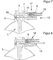
Figur 7 einen mittleren Längsschnitt durch einen Reflektor mit Fassung, Lampe und elektrischen Stecker des zweiten Ausführungsbeispiels, wobei der elektrische Stecker an einem Halter in einer ersten Haltestufe vorverrastet ist, -
Figur 8 den Reflektor nachFigur 7 mit dem elektrischen Stecker in einer zweiten Haltestufe, in der der elektrische Stecker mit Kontaktfahnen der Lampe kontaktiert, -
Figur 9 den Reflektor mit integrierter Fassung, separat montiertem Halter und das Steckergehäuse des elektrischen Steckers und die an elektrische Kabel befestigten Kontaktaufnahmen des elektrischen Steckers, -
Figur 10 eine perspektivische Darstellung nachFigur 9 nach montierter Lampe und -
Figur 11 eine Teildraufsicht nachFigur 10 . - Die in den
Figuren 1 bis 6 und9 bis 11 dargestellte Beleuchtungseinrichtung für Fahrzeuge weist einen schalenförmigen Reflektor 3 auf, der zum Beispiel aus Metall oder Kunststoff aller Art hergestellt ist und an seinem Scheitel mit einer Aufnahmeöffnung 19 für eine Lampe 1 versehen ist. Die Aufnahmeöffnung ist auf der Rückseite des Reflektors 3 von einer ringförmigen Fassung 2 umgeben, die aus einem Metallguss oder aus Kunststoff hergestellt ist. Die Fassung 2 ist an einem Reflektorhals 20, der die Aufnahmeöffnung 19 auf der Rückseite des Reflektors 3 umgibt befestigt. Die Fassung 2 kann einteilig mit dem Reflektor 3 ausgeführt sein. Die ringförmig Fassung 2 weist in ihrer zentralen Öffnung radial nach innen vorspringende Verriegelungsansätzen 21 eines Drehverschlusses 5 auf, die zusammen mit Verriegelungszungen 22 der Lampe den Drehverschluss 5 bilden. Die Lampe 1 weist einen Glaskolben 23 und einen aus Kunststoff oder Keramik bestehenden Sockel 4 auf, zwischen denen die Verriegelungszungen 22 radial nach außen stehen. Der Sockel 4 kann auch einen Adapter aufweisen, der mit einer Lampe (zum Beispiel H7-Lampe) lösbar verbunden ist, die entgegen ihrer Einsetzrichtung weisenden Anschlussfahnen aufweist (nicht dargestellt). Bei der Montage der Lampe 1 wird diese mit ihrem Glaskolben voraus durch die zentrale Öffnung der Fassung 2 hindurch in das Innere des Reflektors 3 geführt. Nach einem Verdrehen der Lampe 1 um ihre Längsachse 6 ist die Lampe 1 mittels des Drehverschlusses 5, der ein Bajonettverschluss ist, in einer verriegelten Endlage an der Fassung 2 befestigt. Dabei ist die Lampe 1 durch Federelemente 24 des Sockels 4 in axialer Richtung gegenüber der Fassung 2 spielfrei gehaltert. Die in der Zeichnung dargestellte Lampe 1 ist bekannt unter der Bezeichnung H11B. Der Sockel 4 der Lampe 1 weist von seiner Mantelfläche zwei radial nach außen stehende Kontaktfahnen 7 auf. Die beiden Kontaktfahnen 7 sind in Einsetzrichtung der Lampe1 gesehen hintereinander angeordnet und als Flachsteckeranschlüsse ausgebildet. Die Kontaktfahnen 7 greifen in Kontaktklammern 25 von Kontaktaufnahmen 8 ein. Weiterhin weisen die Kontaktaufnahmen 8 auf der den Kontaktklammern 25 gegenüberliegenden Seite Kontaktanschlüsse 9 für elektrische Kabel 10 auf. Zwischen den Kontaktklammern 25 und den Kontaktanschlüssen 9 sind die Kontaktaufnahmen 8 mit einem Befestigungsabschnitt 26 versehen. Die Kontaktaufnahmen 8 sind einteilig aus elektrisch leitendem Material wie zum Beispiel Metallblech hergestellt. Die Kontaktanschlüsse 9 sind von Quetschverbindern gebildet, durch die eine unlösbare Verbindung zwischen der Kontaktaufnahme 8 und der elektrischen Seele der Kabel 10 besteht. Die Kontaktaufnahmen 8 sind in Einschubräume 15 eines aus Kunststoff bestehenden Steckergehäuses 14 soweit eingesteckt, bis ein Rastelement des Befestigungsabschnitts 26 der Kontaktaufnahme 8 selbsttätig mit dem Steckergehäuse 14 verrastet. Das Steckergehäuse 14 und die Kontaktaufnahmen 8 bilden zusammen einen elektrischen Stecker 11. Das Steckergehäuse 8 weist eine Befestigungsöffnung 27 auf, durch den der Stecker 11 in Richtung 12 auf einen fingerförmigen Ansatz eines Halters 13 der Fassung 2 (sieheFiguren 1 ,3 ,4 und 5 ) oder des Reflektors 3 (sieheFigur 2 ) oder einen separat auf den Reflektor 3 montierten Halter, der mittels einem Befestigungsmittel 32 am Reflektor 3 befestigt ist (sieheFiguren 9 ,1 und11 ) aufsteckbar ist. Der fingerförmige Halter 13 ist an die Fassung 2 oder den Reflektor 3 angeformt oder als separates Bauteil an dem Reflektor 3 befestigt und verläuft parallel zur einer Tangente der Mantelfläche des Sockels 4. Der fingerförmige Halter 13 weist ein Rastmittel 28 auf, durch das der Stecker 11 bei seinem Aufstecken auf den fingerförmigen Halter 13 selbsttätig mit dem Halter verrastet. Beim Aufstecken des Steckers 11 in Richtung 12 auf den Halter 13 werden gleichzeitig die Kontaktklammern 25 der Kontaktaufnahmen 8 auf die Kontaktfahnen 7 der bereits montierten Lampe 1 aufgesteckt. Die Kontaktfahnen 7 der Lampe 1 ragen durch schlitzartige Durchtrittsöffnungen 16 des Steckergehäuses 14 hindurch und greifen in die Kontaktklammern 25 ein. Die Durchtrittsöffnungen 16 sind an dem den elektrischen Kabeln 10 abgewandten Endabschnitt des Steckergehäuses 14 eingebracht. Dieser Endabschnitt verjüngt sich durch eine schräg oder in einem Bogen verlaufende Seitenfläche 29 zu seinem freien Ende hin. Der Bogen der Seitenfläche verläuft benachbart zur Mantelfläche des Sockels 4. Dadurch sind die Kontaktklammern 25 möglichst nahe zu den Kontaktfahnen 7 angeordnet und die elektrische Kontaktierung ist sicher. Die schlitzartigen Durchtrittsöffnungen 16 verlaufen von der Stirnfläche des Steckergehäuses 14 bis in die bogenförmig verlaufende Seitenfläche 29 hinein. Dadurch ist es möglich, dass nach einem Aufstecken des Steckers 11 auf den Halter 13 die Lampe 1 wechselbar ist ohne den Stecker 11 lösen zu müssen. Um die Lampe 1 einfach und leicht verdrehen zu können weist der Sockel 4 an seiner Rückseite eine rippenartige Handhabe 30 auf. - Die in den
Figuren 7 und 8 dargestellte zweite Ausführungsform einer Beleuchtungseinrichtung für Fahrzeuge weist gegenüber der vorstehend beschriebenen ersten Ausführungsform nachfolgend beschriebene Unterschiede auf. Die Fassung 2 und der fingerförmige Halter 13 sind einteilig mit dem Reflektor 3 aus Kunststoff hergestellt. Der fingerförmige Halter 13 ist an den äußeren freien Rand der Fassung 2 angeformt und erstreckt sich von diesem radial zur Längsachse 6 der Lampe 1 nach außen. Der Stecker 11 ist in Richtung 12, die radial nach innen zur Längsachse 6 weist, auf den fingerförmigen Halter 13 aufgesteckt. Der fingerförmige Halter 13 weist für den elektrischen Stecker 11 eine erste und zweite Haltestufe 17 bzw. 18 auf. In der ersten Haltestufe 17 ist der Stecker 11 vorverrastet gehalten und zu den Kontaktfahnen 8 des Sockels 4 in einem Abstand angeordnet. In dieser Haltestufe 17 kann die Lampe 1 gewechselt werden . Nach dem Wechsel der Lampe 1 wird der Stecker 11 in Richtung 12 zu den Kontaktfahnen 7 hin verschoben, bis die Kontaktklammern 25 auf die Kontaktfahnen 7 aufgesteckt sind und der Stecker 11 in der zweiten Haltestufe 18 mit dem fingerförmigen Halter 13 fest verrastet ist. Die Durchtrittsöffnungen 16 für die Kontaktfahnen 7 des Sockels 4 sind nur in die dem Sockel 4 zugewandten Stirnfläche 31 des Steckergehäuses 14 eingebracht. Dadurch kann in der zweiten Haltestufe 18 des Steckers 11 sich die Lampe 1 nicht ungewollt aus ihrer Endlage herausdrehen. -
- 1. Lampe
- 2. Fassung
- 3. Reflektor
- 4. Sockel
- 5. Drehverschluss
- 6. Längsachse
- 7. Kontaktfahne
- 8. Kontaktaufnahme
- 9. Kontaktanschluss
- 10. elektrisches Kabel
- 11. Stecker
- 12. Richtung
- 13. Halter
- 14. Steckergehäuse
- 15. Einschubraum
- 16. Durchtrittsöffnung
- 17. erste Haltestufe
- 18. zweite Haltestufe
- 19. Aufnahmeöffnung
- 20. Reflektorhals
- 21. Verriegelungsansätze
- 22. Verriegelungszungen
- 23. Glaskolben
- 24. Federelement
- 25. Kontaktklammern
- 26. Befestigungsabschnitt
- 27. Befestigungsöffnung
- 28. Rastmittel
- 29. Seitenfläche
- 30. Handhabe
- 31. Stirnfläche
- 32. Befestigungsmittel
Claims (3)
- Beleuchtungseinrichtung für Fahrzeuge mit mindestens einer Lampe (1) und einer die Lampe (1) aufnehmenden Fassung (2) eines Reflektors (3), wobei die Lampe (1) einen Sockel (4) aufweist, der mittels eines Drehverschlusses (5) in der Fassung (2) lösbar befestigbar ist und transversal zur seiner Längsachse (6) aus dem Sockel (4) hervorstehende Kontaktfahnen (7) aufweist, die nach einer Drehung des Sockels (4) in seine Endstellung mit an den Reflektor (3) angebrachten Kontaktaufnahmen (8) kontaktierbar sind, die einen Kontaktanschluss (9) für elektrische Kabel (10) aufweisen, dass mindestens zwei Kontaktaufnahmen (8) von einem Stecker (11) gebildet sind, der aus einer Richtung (12) mit den Kontaktfahnen (7) der Lampe (1) und einem mit dem Reflektor (3) verbundenen Halter (13) zusammensteckbar ist und der an dem Halter (13) in seiner Endlage festsetzbar ist, wobei die Lampe (1) mindestens zwei radial von dem Sockel (4) nach außen abstehende Kontaktfahnen (7) aufweist, die in Einsetzrichtung der Lampe (1) gesehen hintereinander angeordnet sind, dadurch gekennzeichnet, dass der Halter (13) für den Stecker (11) von einem fingerartige Ansatz gebildet ist, der quer zur Längsachse (6) des Sockels (4) verläuft und radial zur Längsachse (6) des Sockels (4) nach außen hervorsteht, dass das Steckergehäuse (14) für jede Kontaktaufnahme (8) einen Einschubraum (15) aufweist, wobei das Steckergehäuse (14) jeweils eine Durchtrittsöffnung (16) zu den Kontaktaufnahmen (8) in den Einschubräumen (15) aufweist, wobei die Durchtrittsöffnungen (16) von einer Stirnfläche des Steckergehäuses (14) bis in eine bogenförmig verlaufende Seitenfläche eines Endabschnitts des Steckergehäuses (14) verläuft, so dass nach einem Aufstecken des Steckers (11) auf den Halter (13) die Lampe (1) wechselbar ist, ohne den Stecker (11) lösen zu müssen, und so dass bei einer Drehung des Sockels (4) in seiner Endlage seine Kontaktfahnen (7) selbsttätig in die Kontaktaufnahmen (8) eingreifen.
- Beleuchtungseinrichtung nach Anspruch 1, dadurch gekennzeichnet, dass die Kontaktaufnahmen (8) in einem aus Kunststoff bestehenden Steckergehäuse (14) angeordnet sind, das mit dem Halter (13) zusammensteckbar ist.
- Beleuchtungseinrichtung nach Anspruch 1 oder 2, dadurch gekennzeichnet, dass das Steckergehäuse (14) an dem Halter (13) befestigt ist.
Applications Claiming Priority (1)
| Application Number | Priority Date | Filing Date | Title |
|---|---|---|---|
| DE102004045369A DE102004045369A1 (de) | 2004-09-18 | 2004-09-18 | Beleuchtungseinrichtung für Fahrzeuge |
Publications (3)
| Publication Number | Publication Date |
|---|---|
| EP1637803A2 EP1637803A2 (de) | 2006-03-22 |
| EP1637803A3 EP1637803A3 (de) | 2008-09-03 |
| EP1637803B1 true EP1637803B1 (de) | 2020-03-11 |
Family
ID=35501196
Family Applications (1)
| Application Number | Title | Priority Date | Filing Date |
|---|---|---|---|
| EP05108191.7A Expired - Lifetime EP1637803B1 (de) | 2004-09-18 | 2005-09-07 | Beleuchtungseinrichtung für fahrzeuge |
Country Status (2)
| Country | Link |
|---|---|
| EP (1) | EP1637803B1 (de) |
| DE (1) | DE102004045369A1 (de) |
Families Citing this family (6)
| Publication number | Priority date | Publication date | Assignee | Title |
|---|---|---|---|---|
| DE102007011431A1 (de) * | 2007-03-08 | 2008-09-11 | Osram Gesellschaft mit beschränkter Haftung | Scheinwerfer |
| DE102007011432A1 (de) * | 2007-03-08 | 2008-09-11 | Osram Gesellschaft mit beschränkter Haftung | Scheinwerfer |
| DE102010029508A1 (de) * | 2010-05-31 | 2011-12-01 | Osram Gesellschaft mit beschränkter Haftung | Lampe für Fahrzeugscheinwerfer |
| JP5933945B2 (ja) * | 2011-03-24 | 2016-06-15 | スタンレー電気株式会社 | 車両用灯具 |
| ITTO20120668A1 (it) | 2012-07-27 | 2014-01-28 | Automotive Lighting Italia Spa | Dispositivo di illuminazione per veicoli |
| DE102015107137A1 (de) | 2015-03-16 | 2016-09-22 | Hella Kgaa Hueck & Co. | Anordnung einer Lampe an einem Reflektor einer Beleuchtungseinrichtung für ein Fahrzeug |
Family Cites Families (9)
| Publication number | Priority date | Publication date | Assignee | Title |
|---|---|---|---|---|
| DE4139905A1 (de) * | 1991-12-04 | 1993-06-09 | Robert Bosch Gmbh, 7000 Stuttgart, De | Steckverbindung zur kontaktierung einer gasentladungslampe bei einem scheinwerfer |
| JP2000011712A (ja) * | 1998-06-25 | 2000-01-14 | Koito Mfg Co Ltd | 車両用前照灯 |
| DE29823160U1 (de) * | 1998-12-29 | 1999-02-25 | Hugo Schnippering GmbH & Co KG, 58566 Kierspe | Lampenfassung aus Isolierstoff für H 7-Lampen |
| DE19941538A1 (de) * | 1999-09-01 | 2001-03-15 | Hella Kg Hueck & Co | Gerät zur Aufnahme einer Gasentladungslampe eines Fahrzeug-Scheinwerfers |
| DE19951203A1 (de) * | 1999-10-22 | 2001-04-26 | Patent Treuhand Ges Fuer Elektrische Gluehlampen Mbh | Schweinwerferlampe |
| FR2829304B1 (fr) * | 2001-08-31 | 2004-09-17 | Valeo Vision | Agencement pour la connexion electrique d'une lampe |
| DE20300699U1 (de) * | 2003-01-16 | 2003-03-20 | Patent-Treuhand-Gesellschaft für elektrische Glühlampen mbH, 81543 München | Lampensockel und Lampe mit einem Lampensockel |
| FR2852083B1 (fr) * | 2003-03-06 | 2006-04-14 | Valeo Vision | Systeme de fixation pour lampe a verrouillage |
| DE102004004203B4 (de) * | 2004-01-27 | 2008-11-27 | Yazaki Europe Ltd., Hemel Hempstead | Verbindungsanordnung mit einem Verbindungselement und einem Lampensockel |
-
2004
- 2004-09-18 DE DE102004045369A patent/DE102004045369A1/de not_active Withdrawn
-
2005
- 2005-09-07 EP EP05108191.7A patent/EP1637803B1/de not_active Expired - Lifetime
Non-Patent Citations (1)
| Title |
|---|
| None * |
Also Published As
| Publication number | Publication date |
|---|---|
| EP1637803A2 (de) | 2006-03-22 |
| EP1637803A3 (de) | 2008-09-03 |
| DE102004045369A1 (de) | 2006-03-23 |
Similar Documents
| Publication | Publication Date | Title |
|---|---|---|
| DE69823424T2 (de) | Lampenfassung für einen Kraftfahrzeugscheinwerfer und damit ausgerüstetem Scheinwerfer | |
| DE102012109059B4 (de) | Halterung eines Leuchtmittels in der Öffnung eines Reflektors | |
| DE19927198B4 (de) | Lampenfassung aus Isolierstoff | |
| EP1637803A2 (de) | Beleuchtungseinrichtung für Fahrzeuge | |
| EP0766036B1 (de) | Lampenfassung für Kraftfahrzeugscheinwerfer und Kraftfahrzeugscheinwerfer, in den die Lampenfassung eingesetzt ist | |
| DE10148114A1 (de) | Scheinwerferlampe | |
| EP1016818B1 (de) | Lampenfassung aus Isolierstoff für H 7-Lampen | |
| DE3715532C2 (de) | Leuchte für Kraftfahrzeuge, insbesondere vordere Park- und/oder Begrenzungsleuchte für Personenkraftfahrzeuge | |
| EP1524732B1 (de) | Elektrischer Verbinder | |
| DE69902947T2 (de) | Koaxiale kabelverbindungseinrichtung | |
| DE102004004203B4 (de) | Verbindungsanordnung mit einem Verbindungselement und einem Lampensockel | |
| DE102005033882B4 (de) | Beleuchtungseinrichtung für Kraftfahrzeuge, Baugruppe für eine solche Beleuchtungseinrichtung und Verfahren zur Montage einer solchen Beleuchtungseinrichtung | |
| DE4121575C1 (de) | ||
| EP1284388B1 (de) | Beleuchtungseinrichtung für Fahrzeuge | |
| WO2008107433A1 (de) | Scheinwerfer | |
| DE19645647C2 (de) | Lampenhalterung als Bestandteil eines Kraftfahrzeugscheinwerfers | |
| DE3332917C2 (de) | ||
| DE10226489B4 (de) | Anschlussverbinder | |
| DE19861321B4 (de) | Beleuchtungseinrichtung für Fahrzeuge | |
| DE19616257A1 (de) | Lampenfassung für Kraftfahrzeugscheinwerfer und Kraftfahrzeugscheinwerfer, in den die Lampenfassung eingesetzt ist | |
| DE20207527U1 (de) | Lampenfassung für einen Scheinwerfer eines Kraftfahrzeugs | |
| DE19822895A1 (de) | Beleuchtungseinrichtung für Fahrzeuge | |
| EP1439560A2 (de) | Lampensockel und Lampe mit einem Lampensockel | |
| WO2008107435A1 (de) | Scheinwerfer | |
| DE102023122717A1 (de) | Steckverbinder mit variabel anpassbarer Kodierung |
Legal Events
| Date | Code | Title | Description |
|---|---|---|---|
| PUAI | Public reference made under article 153(3) epc to a published international application that has entered the european phase |
Free format text: ORIGINAL CODE: 0009012 |
|
| AK | Designated contracting states |
Kind code of ref document: A2 Designated state(s): AT BE BG CH CY CZ DE DK EE ES FI FR GB GR HU IE IS IT LI LT LU LV MC NL PL PT RO SE SI SK TR |
|
| AX | Request for extension of the european patent |
Extension state: AL BA HR MK YU |
|
| PUAL | Search report despatched |
Free format text: ORIGINAL CODE: 0009013 |
|
| AK | Designated contracting states |
Kind code of ref document: A3 Designated state(s): AT BE BG CH CY CZ DE DK EE ES FI FR GB GR HU IE IS IT LI LT LU LV MC NL PL PT RO SE SI SK TR |
|
| AX | Request for extension of the european patent |
Extension state: AL BA HR MK YU |
|
| 17P | Request for examination filed |
Effective date: 20090302 |
|
| 17Q | First examination report despatched |
Effective date: 20090401 |
|
| AKX | Designation fees paid |
Designated state(s): AT BE BG CH CY CZ DE DK EE ES FI FR GB GR HU IE IS IT LI LT LU LV MC NL PL PT RO SE SI SK TR |
|
| STAA | Information on the status of an ep patent application or granted ep patent |
Free format text: STATUS: EXAMINATION IS IN PROGRESS |
|
| RAP1 | Party data changed (applicant data changed or rights of an application transferred) |
Owner name: HELLA GMBH & CO. KGAA |
|
| GRAP | Despatch of communication of intention to grant a patent |
Free format text: ORIGINAL CODE: EPIDOSNIGR1 |
|
| STAA | Information on the status of an ep patent application or granted ep patent |
Free format text: STATUS: GRANT OF PATENT IS INTENDED |
|
| INTG | Intention to grant announced |
Effective date: 20200109 |
|
| GRAS | Grant fee paid |
Free format text: ORIGINAL CODE: EPIDOSNIGR3 |
|
| GRAA | (expected) grant |
Free format text: ORIGINAL CODE: 0009210 |
|
| STAA | Information on the status of an ep patent application or granted ep patent |
Free format text: STATUS: THE PATENT HAS BEEN GRANTED |
|
| REG | Reference to a national code |
Ref country code: DE Ref legal event code: R081 Ref document number: 502005016128 Country of ref document: DE Owner name: HELLA GMBH & CO. KGAA, DE Free format text: FORMER OWNER: HELLA KGAA HUECK & CO., 59557 LIPPSTADT, DE |
|
| AK | Designated contracting states |
Kind code of ref document: B1 Designated state(s): AT BE BG CH CY CZ DE DK EE ES FI FR GB GR HU IE IS IT LI LT LU LV MC NL PL PT RO SE SI SK TR |
|
| REG | Reference to a national code |
Ref country code: GB Ref legal event code: FG4D Free format text: NOT ENGLISH |
|
| REG | Reference to a national code |
Ref country code: CH Ref legal event code: EP |
|
| REG | Reference to a national code |
Ref country code: AT Ref legal event code: REF Ref document number: 1243555 Country of ref document: AT Kind code of ref document: T Effective date: 20200315 |
|
| REG | Reference to a national code |
Ref country code: DE Ref legal event code: R096 Ref document number: 502005016128 Country of ref document: DE |
|
| REG | Reference to a national code |
Ref country code: IE Ref legal event code: FG4D Free format text: LANGUAGE OF EP DOCUMENT: GERMAN |
|
| PG25 | Lapsed in a contracting state [announced via postgrant information from national office to epo] |
Ref country code: FI Free format text: LAPSE BECAUSE OF FAILURE TO SUBMIT A TRANSLATION OF THE DESCRIPTION OR TO PAY THE FEE WITHIN THE PRESCRIBED TIME-LIMIT Effective date: 20200311 |
|
| REG | Reference to a national code |
Ref country code: NL Ref legal event code: MP Effective date: 20200311 |
|
| PG25 | Lapsed in a contracting state [announced via postgrant information from national office to epo] |
Ref country code: LV Free format text: LAPSE BECAUSE OF FAILURE TO SUBMIT A TRANSLATION OF THE DESCRIPTION OR TO PAY THE FEE WITHIN THE PRESCRIBED TIME-LIMIT Effective date: 20200311 Ref country code: SE Free format text: LAPSE BECAUSE OF FAILURE TO SUBMIT A TRANSLATION OF THE DESCRIPTION OR TO PAY THE FEE WITHIN THE PRESCRIBED TIME-LIMIT Effective date: 20200311 Ref country code: GR Free format text: LAPSE BECAUSE OF FAILURE TO SUBMIT A TRANSLATION OF THE DESCRIPTION OR TO PAY THE FEE WITHIN THE PRESCRIBED TIME-LIMIT Effective date: 20200612 Ref country code: BG Free format text: LAPSE BECAUSE OF FAILURE TO SUBMIT A TRANSLATION OF THE DESCRIPTION OR TO PAY THE FEE WITHIN THE PRESCRIBED TIME-LIMIT Effective date: 20200611 |
|
| REG | Reference to a national code |
Ref country code: LT Ref legal event code: MG4D |
|
| PG25 | Lapsed in a contracting state [announced via postgrant information from national office to epo] |
Ref country code: NL Free format text: LAPSE BECAUSE OF FAILURE TO SUBMIT A TRANSLATION OF THE DESCRIPTION OR TO PAY THE FEE WITHIN THE PRESCRIBED TIME-LIMIT Effective date: 20200311 |
|
| PG25 | Lapsed in a contracting state [announced via postgrant information from national office to epo] |
Ref country code: CZ Free format text: LAPSE BECAUSE OF FAILURE TO SUBMIT A TRANSLATION OF THE DESCRIPTION OR TO PAY THE FEE WITHIN THE PRESCRIBED TIME-LIMIT Effective date: 20200311 Ref country code: IS Free format text: LAPSE BECAUSE OF FAILURE TO SUBMIT A TRANSLATION OF THE DESCRIPTION OR TO PAY THE FEE WITHIN THE PRESCRIBED TIME-LIMIT Effective date: 20200711 Ref country code: RO Free format text: LAPSE BECAUSE OF FAILURE TO SUBMIT A TRANSLATION OF THE DESCRIPTION OR TO PAY THE FEE WITHIN THE PRESCRIBED TIME-LIMIT Effective date: 20200311 Ref country code: SK Free format text: LAPSE BECAUSE OF FAILURE TO SUBMIT A TRANSLATION OF THE DESCRIPTION OR TO PAY THE FEE WITHIN THE PRESCRIBED TIME-LIMIT Effective date: 20200311 Ref country code: PT Free format text: LAPSE BECAUSE OF FAILURE TO SUBMIT A TRANSLATION OF THE DESCRIPTION OR TO PAY THE FEE WITHIN THE PRESCRIBED TIME-LIMIT Effective date: 20200805 Ref country code: LT Free format text: LAPSE BECAUSE OF FAILURE TO SUBMIT A TRANSLATION OF THE DESCRIPTION OR TO PAY THE FEE WITHIN THE PRESCRIBED TIME-LIMIT Effective date: 20200311 Ref country code: EE Free format text: LAPSE BECAUSE OF FAILURE TO SUBMIT A TRANSLATION OF THE DESCRIPTION OR TO PAY THE FEE WITHIN THE PRESCRIBED TIME-LIMIT Effective date: 20200311 |
|
| REG | Reference to a national code |
Ref country code: DE Ref legal event code: R097 Ref document number: 502005016128 Country of ref document: DE |
|
| PLBE | No opposition filed within time limit |
Free format text: ORIGINAL CODE: 0009261 |
|
| STAA | Information on the status of an ep patent application or granted ep patent |
Free format text: STATUS: NO OPPOSITION FILED WITHIN TIME LIMIT |
|
| PG25 | Lapsed in a contracting state [announced via postgrant information from national office to epo] |
Ref country code: ES Free format text: LAPSE BECAUSE OF FAILURE TO SUBMIT A TRANSLATION OF THE DESCRIPTION OR TO PAY THE FEE WITHIN THE PRESCRIBED TIME-LIMIT Effective date: 20200311 Ref country code: IT Free format text: LAPSE BECAUSE OF FAILURE TO SUBMIT A TRANSLATION OF THE DESCRIPTION OR TO PAY THE FEE WITHIN THE PRESCRIBED TIME-LIMIT Effective date: 20200311 Ref country code: DK Free format text: LAPSE BECAUSE OF FAILURE TO SUBMIT A TRANSLATION OF THE DESCRIPTION OR TO PAY THE FEE WITHIN THE PRESCRIBED TIME-LIMIT Effective date: 20200311 |
|
| 26N | No opposition filed |
Effective date: 20201214 |
|
| PG25 | Lapsed in a contracting state [announced via postgrant information from national office to epo] |
Ref country code: SI Free format text: LAPSE BECAUSE OF FAILURE TO SUBMIT A TRANSLATION OF THE DESCRIPTION OR TO PAY THE FEE WITHIN THE PRESCRIBED TIME-LIMIT Effective date: 20200311 Ref country code: PL Free format text: LAPSE BECAUSE OF FAILURE TO SUBMIT A TRANSLATION OF THE DESCRIPTION OR TO PAY THE FEE WITHIN THE PRESCRIBED TIME-LIMIT Effective date: 20200311 |
|
| PG25 | Lapsed in a contracting state [announced via postgrant information from national office to epo] |
Ref country code: MC Free format text: LAPSE BECAUSE OF FAILURE TO SUBMIT A TRANSLATION OF THE DESCRIPTION OR TO PAY THE FEE WITHIN THE PRESCRIBED TIME-LIMIT Effective date: 20200311 |
|
| REG | Reference to a national code |
Ref country code: CH Ref legal event code: PL |
|
| GBPC | Gb: european patent ceased through non-payment of renewal fee |
Effective date: 20200907 |
|
| REG | Reference to a national code |
Ref country code: BE Ref legal event code: MM Effective date: 20200930 |
|
| PG25 | Lapsed in a contracting state [announced via postgrant information from national office to epo] |
Ref country code: LU Free format text: LAPSE BECAUSE OF NON-PAYMENT OF DUE FEES Effective date: 20200907 |
|
| PG25 | Lapsed in a contracting state [announced via postgrant information from national office to epo] |
Ref country code: BE Free format text: LAPSE BECAUSE OF NON-PAYMENT OF DUE FEES Effective date: 20200930 Ref country code: CH Free format text: LAPSE BECAUSE OF NON-PAYMENT OF DUE FEES Effective date: 20200930 Ref country code: GB Free format text: LAPSE BECAUSE OF NON-PAYMENT OF DUE FEES Effective date: 20200907 Ref country code: IE Free format text: LAPSE BECAUSE OF NON-PAYMENT OF DUE FEES Effective date: 20200907 Ref country code: LI Free format text: LAPSE BECAUSE OF NON-PAYMENT OF DUE FEES Effective date: 20200930 |
|
| REG | Reference to a national code |
Ref country code: AT Ref legal event code: MM01 Ref document number: 1243555 Country of ref document: AT Kind code of ref document: T Effective date: 20200907 |
|
| PG25 | Lapsed in a contracting state [announced via postgrant information from national office to epo] |
Ref country code: AT Free format text: LAPSE BECAUSE OF NON-PAYMENT OF DUE FEES Effective date: 20200907 |
|
| PG25 | Lapsed in a contracting state [announced via postgrant information from national office to epo] |
Ref country code: TR Free format text: LAPSE BECAUSE OF FAILURE TO SUBMIT A TRANSLATION OF THE DESCRIPTION OR TO PAY THE FEE WITHIN THE PRESCRIBED TIME-LIMIT Effective date: 20200311 Ref country code: CY Free format text: LAPSE BECAUSE OF FAILURE TO SUBMIT A TRANSLATION OF THE DESCRIPTION OR TO PAY THE FEE WITHIN THE PRESCRIBED TIME-LIMIT Effective date: 20200311 |
|
| PGFP | Annual fee paid to national office [announced via postgrant information from national office to epo] |
Ref country code: DE Payment date: 20220609 Year of fee payment: 18 |
|
| PGFP | Annual fee paid to national office [announced via postgrant information from national office to epo] |
Ref country code: FR Payment date: 20220709 Year of fee payment: 18 |
|
| REG | Reference to a national code |
Ref country code: DE Ref legal event code: R119 Ref document number: 502005016128 Country of ref document: DE |
|
| PG25 | Lapsed in a contracting state [announced via postgrant information from national office to epo] |
Ref country code: FR Free format text: LAPSE BECAUSE OF NON-PAYMENT OF DUE FEES Effective date: 20230930 Ref country code: DE Free format text: LAPSE BECAUSE OF NON-PAYMENT OF DUE FEES Effective date: 20240403 |