EP1632909B1 - Vorrichtung zur Bearbeitung von Papiergeld - Google Patents
Vorrichtung zur Bearbeitung von Papiergeld Download PDFInfo
- Publication number
- EP1632909B1 EP1632909B1 EP05011216.8A EP05011216A EP1632909B1 EP 1632909 B1 EP1632909 B1 EP 1632909B1 EP 05011216 A EP05011216 A EP 05011216A EP 1632909 B1 EP1632909 B1 EP 1632909B1
- Authority
- EP
- European Patent Office
- Prior art keywords
- information
- bill
- bills
- transaction
- discriminative
- Prior art date
- Legal status (The legal status is an assumption and is not a legal conclusion. Google has not performed a legal analysis and makes no representation as to the accuracy of the status listed.)
- Expired - Lifetime
Links
Images


Classifications
-
- G—PHYSICS
- G07—CHECKING-DEVICES
- G07F—COIN-FREED OR LIKE APPARATUS
- G07F19/00—Complete banking systems; Coded card-freed arrangements adapted for dispensing or receiving monies or the like and posting such transactions to existing accounts, e.g. automatic teller machines
- G07F19/20—Automatic teller machines [ATMs]
- G07F19/202—Depositing operations within ATMs
-
- G—PHYSICS
- G07—CHECKING-DEVICES
- G07D—HANDLING OF COINS OR VALUABLE PAPERS, e.g. TESTING, SORTING BY DENOMINATIONS, COUNTING, DISPENSING, CHANGING OR DEPOSITING
- G07D11/00—Devices accepting coins; Devices accepting, dispensing, sorting or counting valuable papers
- G07D11/20—Controlling or monitoring the operation of devices; Data handling
- G07D11/30—Tracking or tracing valuable papers or cassettes
-
- G—PHYSICS
- G07—CHECKING-DEVICES
- G07D—HANDLING OF COINS OR VALUABLE PAPERS, e.g. TESTING, SORTING BY DENOMINATIONS, COUNTING, DISPENSING, CHANGING OR DEPOSITING
- G07D11/00—Devices accepting coins; Devices accepting, dispensing, sorting or counting valuable papers
- G07D11/20—Controlling or monitoring the operation of devices; Data handling
- G07D11/32—Record keeping
- G07D11/36—Auditing of activities
-
- G—PHYSICS
- G07—CHECKING-DEVICES
- G07F—COIN-FREED OR LIKE APPARATUS
- G07F19/00—Complete banking systems; Coded card-freed arrangements adapted for dispensing or receiving monies or the like and posting such transactions to existing accounts, e.g. automatic teller machines
- G07F19/20—Automatic teller machines [ATMs]
Definitions
- the present invention relates to a paper money handling apparatus, and more particularly to management of securities such as bills, including validation of true securities against false ones and protection from illicit use by applying IC chips. It relates to, for instance, a managing method and system for bills in which wireless IC chips are embedded to be handled by automatic teller machines (ATMs).
- ATMs automatic teller machines
- Patent Reference 1 Japanese Published Unexamined Patent Application No. 2001-260580
- JP 2001260580 discloses securities in which non-contact wireless IC chips (e.g. RFID) are embedded and information in the IC chips is made rewritable together with a method and a system of preventing illicit use of such securities.
- non-contact wireless IC chips e.g. RFID
- Patent Reference 2 Japanese Published Unexamined Patent Application No. 2003-178185
- JP 2003178185 discloses a securities processing system which registers in advance in a database (DB) ID information (and securities information) regarding securities in which IC chips storing ID information are embedded and determines validity or invalidity of securities at the time of issue by referencing this ID information registered in the DB.
- DB database
- ID information and securities information
- Patent Reference 3 Japanese Published Unexamined Patent Application No. 2004-164156 JP 2004164156 discloses a cash processing machine enabled to discriminate individual bills even if some of them are sticking to each other by providing each sheet with a built - in wireless IC and equipping the bill discriminator arranged on the bill conveying path with an antenna communicating with the wireless ICs.
- serial number of alphabetic letters and numerals isolated from the rest of the read image of the bill requires a color sensor of a high reading resolution, sophisticated image processing techniques and character reading techniques.
- serial numbers assigned to bills are virtual numbers only for temporary use while the bills are conveyed within the ATM, and the bank attendant cannot visually recognize such serial numbers of bills having passed the ATM in his or her charge. Moreover, if bills become jammed during their conveyance and the attendant extracts the jammed bills, this will constitute a factor of uncertainty, which ruins the precondition of assigning the virtual serialnumbers. For this reason, it is diff icult to uniquely identify each individual bank note in the ATM.
- US 2004/0039479 A1 discloses an apparatus for processing sheet material, in particular bank notes, comprising a processing device having at least one means for generating information on the processing of individual sheets of sheet material, and a monitoring device.
- the processing device has at least one means for detecting the identity of individual sheets and the monitoring device includes at least one memory device for storing information on the processing of individual sheets together with the identity of the individual sheets.
- the storage of information on processing together with the identity of individual sheets obtains a unique association of a processed individual sheet with the information generated during processing of said sheet, for example data on authenticity or fitness testing, sorting, demonetizing or destruction.
- the identity of individual sheets is preferably given by image data of the particular sheets. This is, for example, a picture of a printed sheet taken by a CCD camera. Additionally or alternatively, in particular in the case of bank notes, the identity of a sheet can be given by its serial number. Acquisition of the image data and/or serial number permits the identity of a printed sheet or bank note to be uniquely detected.
- a related apparatus is disclosed in DE 101 07 344 A1 . Both those apparatus identify bills by the serial numbers printed thereon.
- paper money sheets in the context of the invention include bills, promissory notes, checks, share certificates, bonds and gift certificates
- An ATM is usually equipped with a bill recycling mechanism (BRM), which accepts bills deposited into the ATM and uses them to respond to withdrawing transactions by customers.
- BRM bill recycling mechanism
- This embodiment uses bills each of which has, embedded in one of its corners, a wireless IC chip having unique identifying information (ID number).
- ID number The number of digits of information recorded on the IC chip is, for instance, 128.
- the information to identify a bill may include unique items such as its issuing country, denomination, version number (new or old), the production number at the printing bureau, and the history of changes in production. It is not necessary to use all the 128 digits, some of which may remain unused.
- the ID number of the IC chip is read by a wireless IC reader disposed somewhere on the conveying path, for instance the bill discriminator of the ATM.
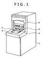
- FIG. 1 shows an external view of the ATM.
- An ATM 1 has a display unit 2 for displaying guidance to users, a manipulating unit 3 for receiving manipulation inputs by way of buttons or a touch panel in accordance with a guidance display on the display unit 2, and a cash slot 4 for accepting bill deposits and delivering payable bills.
- a customer-owned cash card is inserted into a card/slip processing mechanism 6, wherein card processing and transaction processing take place.
- a shutter 5 is arranged above the cash slot 4. The customer puts bills within the shutter 5 when depositing money, or takes out bills discharged inside the shutter 5 when withdrawing money.
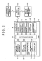
- Fig. 2 is a control block diagram of the ATM.
- a customer-operable unit having the aforementioned display unit 2 and manipulating unit 3, the card/slip processing mechanism 6 and a paper money recycling mechanism 10 are connected to a main controller 32, and necessary operations are performed under the control of the main controller 32.
- the main controller 32 is also connected to an attendant-operable unit 7, an external memory device (HDD) 8, an interfacing device 9 and a clock mechanism 13, and transfers necessary data to and from these units.
- the main controller 32 has a processor and a memory to process and store various data regarding cash transactions.
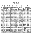
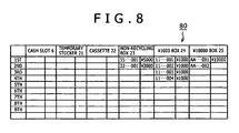
- a bill management table 70 shown in Fig. 7 a bill management table 80 whose contents are classified by the storing position shown in Fig. 8 , and a registration-sequenced bill information table 90 shown in Fig. 9 are stored in the external memory device 8.
- the bill management table 70 management information regarding bills is registered with the ID numbers of bills being used as the keys.
- the ID numbers of bills stored in each bill storing box are registered. Items of bill information registered in the bill management table 70 are acquired, rearranged in the order of ID numbers and registered in the registration-sequenced bill information table 90 in that rearranged order.
- the clock mechanism 13 which is a calendar clock keeping time by the year, month, day, hour, minute and second, informs the main controller 32 of the time of each transaction of depositing, withdrawing or the like by a customer.
- a power supply unit 11 supplies electric power to the main controller 32, the aforementioned mechanisms and constituent parts.
- the interfacing device 9 is connected to and exchanges necessary data with a host computer 12 installed at the computation center of the financial institution.
- the format of the telegraphs exchanged between the ATM 1 and the host computer 12 includes such items of information as the financial institution number, branch number, apparatus type, apparatus number, account type, account number, password, transaction type and sum as shown in Fig. 10 .
- the host computer 12 is equipped with a large-capacity memory device for managing information on customers' accounts.
- the host computer 12 is also connected to a management center 14 jointly managed by a plurality of financial institutions and a bill ID number management center 15 established at the Bank of Japan.
- a management center 14 jointly managed by a plurality of financial institutions and a bill ID number management center 15 established at the Bank of Japan.
- information on bills collected from the host computers 12 of financial institutions is managed with the ID numbers of bills being used as the keys.
- the ID number 71 has a position in sequence 72, a transaction type 73, an account number 74, a time 75, a bill feed source 76, a bill store destination 77 and a validation result 78 are registered in the bill management table 70.
- the position in sequence 72 means the position in the sequence of bill handling; position 1, for instance, is a mode in which the attendant of the financial institution or somebody else inserts a cassette 22 into the ATM and loads a storing box with bills in the cassette. Since no transaction by any customer is involved in this mode, no account number is registered. It concerns a state of management in which true ⁇ 1000 real notes have been transferred from the cassette in the bill feed source 76 to a ⁇ 1000 box in the bill store destination 77.
- the storing position-based bill management table 80 successively memorizes and holds the ID numbers of bills, classified by the location in which they are stored, namely a non-recycling box 23, ⁇ 1000 box 24 or a ⁇ 10000 box 25. Since this storing position-based bill management table 80 dynamically manages bills, keeping the increase or decrease of bills on a real time basis, the ID numbers of bills delivered out and discharged from the ⁇ 1000 box 24 and the ⁇ 10000 box 25, both of which are recycling boxes, are erased.
- the registration-sequenced bill information table 90 is prepared by rearranging under the control of the main controller 32 the contents of the bill management table 70 shown in Fig. 7 into the order of ID numbers of bills with the ID number being used as the keys. It is preferable for the updating of the registration-sequenced bill information table 90 to be processed with reference to the bill management table 70 on a real time basis every time one transaction has been completed.
- Fig. 3 shows the configuration of the bill recycling mechanism (BRM) 10.
- the BRM 10 is a mechanism for handling bills within the ATM 1; in the illustration, the right hand side is toward the user.
- An intermediate plate 28 is disposed within the cash slot 4 to partition the slot into an in-portion and an out-portion.
- a discriminator 20 for identifying the denominations of ⁇ 1000, ⁇ 10000 and other bills and performing true/false determination of bills; a temporary stocker 21 for temporarily holding bills having passed the discriminator 20 until the customer confirms the sum to be deposited; a non-recycling box 23 for storing ⁇ 5000 bills, which are not used for payment to customers, and too heavily damaged bills for recycling; the ⁇ 1000 box 24, the ⁇ 10000 box 25 for storing ⁇ 10000 bills and other units are linked to the conveying path 27 which is linked to the cash slot 4.
- bills are pinched between belts or rollers when they are conveyed over the conveying path 27, which is equipped, where required, with gates 26a through 26e for switching the direction of conveying the bills.
- the ⁇ 1000 box 24 and the ⁇ 10000 box 25 are collectively referred to as the recycling boxes.
- a cassette 22 for loading the recycling boxes with bills and holding the bills picked up by the attendant from the recycling boxes to be carried away.
- the discriminator 20 is provided with a surface information reader 29 for optically or magnetically reading surface information, such as patterns and characters, on the surface of each bill to identify the denomination and perform true/false determination of bills and an IC reader 30 for reading ID information of the IC chip embedded in each bill.
- the IC reader 30 includes an antenna to be used for the transmission and reception mainly of electromagnetic waves and a signal processor for processing signals transmitted to or received from IC chips.
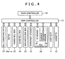
- Fig. 4 is a functional block diagram of the BRM 10.
- a BRM controller 31 is connected to the main controller 32, controls the BRM 10 in accordance with instructions from the main controller 32 and the detected state of the BRM 10, and transmits as required information on the BRM 10 to the main controller 32.
- the same elements as their counterparts in Figs. 2 and 3 are denoted by respectively the same reference signs, and their description will not be duplicated.
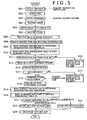
- a transaction selecting screen is displayed on the display unit 2.
- the customer manipulates the manipulating unit 3 to select "Deposit” and enters it (S01).
- the main controller 32 acquires the type of transaction selected by the customer, and stores it into a memory (not shown).
- the customer inserts a cash card into the medium slit of the card/slip processing mechanism 6 (S02).
- the card processing mechanism reads information stored in the card, namely information items including the customer's account number, and similarly stores that information into the memory of the main controller 32.
- the shutter 5 of the cash slot 4 opens (S04).
- a bill or bills are put into the in-portion (toward the customer) of the cash slot 4 (S05)
- bills are fed out to the conveying path 27 after the shutter 5 is closed (S06) and conveyed via the gate 26a to the discriminator 20 (S07).
- the bills first undergo reading of the ID numbers of their respective IC chips by the IC reader 30 (S08). Then, the surface information reader 29 reads such items of surface information as the patterns and characters printed on and the degree of magnetization and thickness of the bills to identify the denomination and perform true/false determination of the bills (S09).
- the BRM controller 31 successively transmits to the main controller 32 the items of ID information read by the IC reader 30. Since the BRM controller 31 can sense handling information on the bills, namely the situational factors of the bill bearing a given ID number, such as its feed source, position in the sequence of bills fed from that source, destination and position in the sequence of bills stored into that destination, the main controller 32 successively collects such bill management information.
- the main controller 32 then puts together information on the state of the bills, including the type of transaction selected by the customer and the customer's account number, with the ID numbers of bills collected from the BRM controller 31 being used as the keys, and registers it as new management information in the bill management table 70 ( Fig. 7 ) stored in the external memory device 8 (S10).
- the total sum of the bills found true is displayed on the display unit 2, and a confirmation input by the customer through the manipulating unit 3 is awaited (S14).
- the contents of the bill management table 70 then are a group of data in the state of position 2 in Fig. 7 .
- the main controller 32 will transmit transaction information to the host computer 12 via the interfacing device 9 to update the balance of the customer's pertinent account (S16). On this occasion, it acquires the customer's transaction time.
- bills held in the temporary stocker 21 are fed out to the conveying path 27 via the gate 26b, and conveyed to the discriminator 20 (S18).
- Each bill passing the discriminator 20 first undergoes reading of its surface information by the surface information reader 29, and its denomination and validity are determined (S19). Then the ID number of its IC chip is read by the IC reader 30, and this ID number, together with information on the result of discrimination of the bill, is transferred to the main controller 32 to be stored into the bill management table 70 in the external memory device 8 (S20).
- Bills are classified by the denomination and the result of true/false determination (S21), and stored into corresponding storing boxes.
- ⁇ 1000 bills are stored into the ⁇ 1000 box 24 and ⁇ 10000 bills, into the ⁇ 10000 box 25 (S23). Since ⁇ 2000 and ⁇ 5000 bills are not used for payment to customers, they are collected into the non-recycling box 23 (S22).
- the contents of the bill management table at the time of this storing are in the state of position 3 in the management table shown in Fig. 7 .
- the ⁇ 10000 bill of ID No. AA--002 though it is found dubious in the discrimination procedure, is found true in the second block of deposition, with its ID number being read too, and therefore deemed true to be stored into the ⁇ 10000 box 25.
- the setting can be altered for more strict management of the state of bills to collect any bill once found dubious into the non-recycling box 23.
- the main controller 32 is aware of the state of each bill when it is finally stored into a storing box, the contents of the storing position-based bill management table 80 are also updated on this occasion.
- the customer's cash card and a transaction slip is discharged from the medium slit of the card/slip processing mechanism 6 (S24), and the customer receives them to end the sequence of transaction.
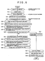
- Fig. 6 is a flowchart of paper money handling in a withdrawing transaction by another customer.
- the customer manipulates the manipulating unit 3 to select "Withdraw” (S51) and then inserts his or her cash card (S52).
- the customer enters a password into the manipulating unit 3 (S53) and then inputs the sum to be withdrawn (S54).
- the transaction information acquired in this way is transmitted from the ATM 1 to the host computer 12, and communication with the center thus takes place between the ATM 1 and the host computer 12 (S55).
- the host computer 12 confirms the identity of the customer by checking the entered password, updates the account balance, and transmits a payment permit to the ATM 1.
- the ATM 1 receives the payment permit, the BRM 10 successively feeds out bills in the amount of requested withdrawal from recycling boxes to the conveying path 27 (S56).
- Each bill passing the discriminator 20 first undergoes reading of the ID number of its IC chip by the IC reader 30 (S57). Then, the surface information reader 29 reads such items of surface information as the patterns and characters printed on and the degree of magnetization and thickness of the bills to identify the denomination and perform true/false determination of the bills (S58). The bill information acquired in this way is stored under the control of the main controller 32 into the bill management table 70 with the ID numbers of bills being used as the keys (S59).
- the bills in the temporary stocker 21 are fed out onto the conveying path 27 via the gate 26b and conveyed to the discriminator 20 (S63).
- Each bill passing the discriminator 20 undergoes reading of surface information by the surface information reader 29 to be determined whether it is true or false (S64).
- the IC reader 30 reads the ID number of its IC chip, and these items of bill information are stored into the bill management table 70 with the ID number as the key (S65), and the bills are stored into the non-recycling box 23 (S66).
- the contents of the bill management table 70 at this point of time are in the state of position 4 in the table shown in Fig. 7 .
- the ⁇ 1000 bill of ID number 11--004 though found "Inclination abnormal" because of its poor fed-out state, is found true also in storing for deposition, with its ID number being accurately read too, and therefore deemed to be a true ⁇ 1000 bill to be conveyed to the out-portion of the cash slot 4.
- the ID number of any bill fails to be read, it is also possible to infer the ID number of this bill from information on the bills stored immediately before and after this one by referencing the bill management table 70 of Fig. 7 , and restore its ID number. For instance, since bills stored into a recycling box are fed out in an order reverse to that of their storing, even if the ID number of any one bill fails to be read when it is to be paid out or this bill fails to be discriminated accurately, it is possible to restore the bill information which has failed to be read accurately by referencing the bill management table 70 and acquiring information on the bill at the time it was accepted and stored.
- the shutter 5 of the cash slot 4 is opened (S67), enabling the customer to receive the bills to be withdrawn (S68). After that, his or her cash card and a slip are discharged from the ATM 1 (S69), which the customer receives to end the sequence of transaction.
- the whereabouts of any bill can be found out by referencing this table 90.
- the source of a bill bearing a certain ID number i.e. the account number of the customer who deposited it, and its destination, the account number of the customer who withdrew it can be known.
- the attendant-operable unit 7 of the ATM 1 is also equipped with a display unit and a manipulating unit for inputting to be used by the attendant, similar to those of the customer-operable unit.
- the attendant-operable unit 7 and the main controller 32 serve here as information searching means.
- the registration-sequenced bill information table 90 it is possible to keep trace of any illicit act by the attendant of the financial institution by utilizing the registration-sequenced bill information table 90. If, for instance, the attendant is to manipulate the attendant-operable unit 7, he or she is required to enter a password for the attendant's exclusive use. This exclusive password and the time of manipulation by the attendant are registered in the external memory device 8 as logs. By collating this log information with the contents of the registration-sequenced bill information table 90, any bill inadvertently picked up by the attendant from anywhere in the ATM can also be kept trace of.
- a management center 15 equipped with a database for managing paper money ID numbers at the Bank of Japan, the issuing source of bills, and to collect similar information to what was described above at this center 15.
- Such a system would make possible true/false discrimination and keeping trace of bills by making inquiries by the ID number and moreover to establish a system of bill tracing and security on a nationwide scale.
- the results of bill validation are cumulatively stored with the ID number of the IC chips of bills being used as the key every time a bill moves in the ATM, the accuracy (reliability) of bill validation is enhanced. Even if the results of identifying the denomination at different times differ, the bill concerned will be collected into the non-recycling box, and accordingly wrong discrimination can be prevented.
- any such a bill in the ATM can be located or its owner identified and confirmed by searching the tables 70, 80 and 90 by using the ID number of the bill used as the key, resulting in enhanced security.
- the tables 70, 80 and 90 in this embodiment are described to be stored in the external memory device 8 within the ATM 1.
- DB database
- the server Since bill-related information is transmitted from a plurality of ATMs installed in each branch to the server, the server has to register the machine number of the ATM which has handled each bill correspondingly to the ID number of the bill in addition to the contents of the tables 70, 80 and 90.
- Searching of bill-related data stored in the DB of the server is accomplished by the attendant using a personal computer (PC). In this sense, the PC serves as information searching means. Incidentally, bill-related are transmitted to the host computer 14 from this server.
- PC personal computer
- paper money sheets in the apparatus can be accurately located and their movements readily kept trace of on the basis of distinguishing information held by IC chips.
- an apparatus handling bills for instance by storing in memory means discriminative information based on surface information on bills and discriminative information held by IC chips matched with each other, even where discriminative information based on bill surface information cannot be normally acquired, the bills can be smoothly and effectively handled by utilizing the discriminative information held by IC chips.
- the bill searched for can be detected by searching the contents of the memory means. Any non-real paper money sheet or the like can also be kept trace of by using discriminative information held by IC chips as the key.
Landscapes
- Physics & Mathematics (AREA)
- General Physics & Mathematics (AREA)
- Business, Economics & Management (AREA)
- Accounting & Taxation (AREA)
- Finance (AREA)
- Financial Or Insurance-Related Operations Such As Payment And Settlement (AREA)
- Inspection Of Paper Currency And Valuable Securities (AREA)
Claims (8)
- Notenhandhabungsvorrichtung aufweisend:eine Manipulationseinheit (3) zum Auswählen der Art einer Transaktion zur Ausführung durch einen Kunden;eine Steuerung (32) zum Erkennen der Art der Transaktion, die mit der Manipulationseinheit ausgewählt wurde;einen Förderweg (27) zum Fördern einer Note;einen Notenunterscheider (20, 29) zum Lesen von Oberflächeninformationen von einer über den Förderweg geförderten Note und zum Ausführen einer Echt-/Falsch-Bestimmung der Note;eine Speichereinheit (8, 70, 90) zum Speichern von Informationen über das Ergebnis der Bestimmung durch den Notenunterscheider (20, 29) und Informationen über die von der Steuerung (32) erkannte Art der Transaktion durch den Kunden; undeinen drahtlosen IC-Leser (30) zum Lesen eindeutiger Unterscheidungsinformationen, die von einem IC-Chip in der geförderten Note gehalten werden, wobei:die Speichereinheit eine erste und eine zweite Notenverwaltungstabelle (70, 90) speichert,die erste Notenverwaltungstabelle (70) die Unterscheidungsinformationen, die Informationen über das Ergebnis der Bestimmung und die Informationen über die Art der Transaktion kumulativ jedes Mal aufzeichnet, wenn eine Note durch den drahtlosen IC-Leser (30) und den Notenunterscheider (20, 29) hindurchtritt, unddie zweite Notenverwaltungstabelle (90) die Unterscheidungsinformationen, die Informationen über das Ergebnis der Bestimmung und die Informationen über die Art der Transaktion aus der ersten Tabelle umgeordnet in der Reihenfolge der Unterscheidungsinformationen verzeichnet, sodass die zweite Notenverwaltungstabelle unter Bezugnahme auf die Unterscheidungsinformationen nach den verzeichneten Informationen über das Ergebnis der Bestimmung und den Informationen über die Art der Transaktion durchsucht werden kann.
- Notenhandhabungsvorrichtung nach Anspruch 1, aufweisend:eine Wartungsbedienungseinheit (7) zur Bedienung durch Wartungspersonal, wobeidie Steuerung (32) eingerichtet ist, entsprechend einer Anweisung von der Wartungsbedienungseinheit eine Suche in der ersten und/oder der zweiten Notenverwaltungstabelle (70, 90) vorzunehmen.
- Notenhandhabungsvorrichtung nach Anspruch 1, wobei
die Steuerung (32) eingerichtet ist, entsprechend den in der ersten und/oder in der zweiten Notenverwaltungstabelle (70, 90) verzeichneten Unterscheidungsinformationen zu entscheiden, ob eine Note ausgegeben werden soll, wenn die Note während einer Ausgabe nicht vom Notenunterscheider (20, 29) als echt oder falsch bestimmt werden kann. - Notenhandhabungsvorrichtung nach Anspruch 1, wobei
die Informationen über die Art der Transaktion eine Kontonummer des Kunden enthalten. - Notenverwaltungsverfahren zur Verwendung in einer Notenhandhabungsvorrichtung, die Noten mit jeweils einem IC-Chip handhabt, der eindeutige Unterscheidungsinformationen hält, mit folgenden Schritten:Erkennen der Art einer Transaktion zur Ausführung durch einen die Notenhandhabungsvorrichtung verwendenden Kunden;Fördern von Noten über einen Förderweg (27) für Transaktionen mit Kunden;Lesen von Oberflächeninformationen auf den geförderten Noten und Ausführen einer Echt-/Falsch-Bestimmung der Noten durch einen auf dem Förderweg installierten Notenunterscheider (20, 29);Lesen der von den IC-Chips auf den geförderten Noten gehaltenen Unterscheidungsinformationen mittels eines drahtlosen IC-Lesers (30); undSpeichern von Informationen über ein Ergebnis der von dem Notenunterscheider ausgeführten Bestimmung, der von dem IC-Leser gewonnenen Unterscheidungsinformationen und von Informationen über die erkannte Art der Transaktion in eine Speichereinheit (8) mit einer ersten und einer zweiten Notenverwaltungstabelle (70, 90), wobeidie erste Notenverwaltungstabelle (70) die Unterscheidungsinformationen, die Informationen über das Ergebnis der Bestimmung und die Informationen über die Art der Transaktion kumulativ jedes Mal dann aufzeichnet, wenn eine Note durch den drahtlosen IC-Leser (30) und den Notenunterscheider (20, 29) hindurchtritt, unddie zweite Notenverwaltungstabelle (90) die Unterscheidungsinformationen, die Informationen über das Ergebnis der Bestimmung und die Informationen über die Art der Transaktion aus der ersten Tabelle umgeordnet in der Reihenfolge der Unterscheidungsinformationen verzeichnet, sodass die zweite Notenverwaltungstabelle unter Bezugnahme auf die Unterscheidungsinformationen nach den verzeichneten Informationen über das Ergebnis der Bestimmung und den Informationen über die Art der Transaktion durchsucht werden kann.
- Verfahren nach Anspruch 5, wobei
abgestimmt mit den Unterscheidungsinformationen eine Kontonummer, die von einer vom Kunden verwendeten Karte gewonnen wird, und Informationen über die Zeit, zu der die Transaktion durchgeführt wurde, gespeichert werden. - Verfahren nach Anspruch 5 oder 6 mit einem Informationssuchschritt zum Suchen nach in der Speichereinheit (8) gespeicherten Informationen unter Verwendung der Unterscheidungsinformationen als Schlüssel.
- Verfahren nach einem der Ansprüche 5 bis 6 mit einem Schritt zum Hinzufügen von maschinenspezifischen Informationen über die Notenhandhabungsvorrichtung zu den in der Speichereinheit (8) gespeicherten Informationen und zum Übermitteln der so angereicherten Informationen an einen Hostcomputer (12, 14, 15), mit dem die Notenhandhabungsvorrichtung verbunden ist.
Applications Claiming Priority (1)
| Application Number | Priority Date | Filing Date | Title |
|---|---|---|---|
| JP2004255327A JP4528067B2 (ja) | 2004-09-02 | 2004-09-02 | 紙幣取扱装置、紙幣管理システム、紙幣管理方法、および紙葉類取扱装置 |
Publications (2)
| Publication Number | Publication Date |
|---|---|
| EP1632909A1 EP1632909A1 (de) | 2006-03-08 |
| EP1632909B1 true EP1632909B1 (de) | 2016-01-06 |
Family
ID=35198090
Family Applications (1)
| Application Number | Title | Priority Date | Filing Date |
|---|---|---|---|
| EP05011216.8A Expired - Lifetime EP1632909B1 (de) | 2004-09-02 | 2005-05-24 | Vorrichtung zur Bearbeitung von Papiergeld |
Country Status (3)
| Country | Link |
|---|---|
| US (1) | US7458506B2 (de) |
| EP (1) | EP1632909B1 (de) |
| JP (1) | JP4528067B2 (de) |
Families Citing this family (35)
| Publication number | Priority date | Publication date | Assignee | Title |
|---|---|---|---|---|
| JP4580168B2 (ja) * | 2001-08-30 | 2010-11-10 | 富士通株式会社 | 自動金銭取引装置 |
| JP4832026B2 (ja) * | 2005-08-25 | 2011-12-07 | ローレル精機株式会社 | 紙幣処理機 |
| EP1952363A1 (de) * | 2005-11-24 | 2008-08-06 | Consensum As | Verfahren zur handhabung einer banknote und system dafür |
| JP5148087B2 (ja) * | 2006-08-17 | 2013-02-20 | ローレル精機株式会社 | 紙幣処理機 |
| JP4451891B2 (ja) * | 2007-03-19 | 2010-04-14 | サンデン株式会社 | 電子マネー入金機 |
| KR101754051B1 (ko) * | 2007-04-24 | 2017-07-04 | 글로리 글로벌 솔루션스 (인터내셔널) 리미티드 | 물품을 분류하기 위한 방법 및 장치 |
| JP5156439B2 (ja) * | 2008-03-12 | 2013-03-06 | 日立オムロンターミナルソリューションズ株式会社 | 紙幣取扱装置及び現金自動取引装置 |
| JP5150342B2 (ja) * | 2008-04-14 | 2013-02-20 | 日立オムロンターミナルソリューションズ株式会社 | 紙幣取扱装置 |
| US8579191B2 (en) * | 2008-06-27 | 2013-11-12 | Diebold Self-Service Systems, Division Of Diebold, Incorporated | Automated banking system controlled responsive to data bearing records |
| US8227936B1 (en) | 2008-07-31 | 2012-07-24 | Bank Of America Corporation | Cash handling device having integrated uninterruptible power supply |
| US8181854B1 (en) | 2008-07-31 | 2012-05-22 | Bank Of America Corporation | Cash handling device having integrated wireless modem |
| US8025214B1 (en) | 2008-07-31 | 2011-09-27 | Bank Of America Corporation | Cash handling device having integrated controller |
| WO2010035346A1 (ja) * | 2008-09-29 | 2010-04-01 | グローリー株式会社 | 紙幣処理システムおよび紙幣処理方法 |
| KR101026151B1 (ko) * | 2008-10-27 | 2011-04-05 | 노틸러스효성 주식회사 | 지폐번호 인식기능을 가진 금융자동화기기 및 이를 이용한 고액권지폐 관리방법 |
| DE102009035028A1 (de) * | 2009-07-28 | 2011-02-03 | Wincor Nixdorf International Gmbh | Vorrichtung zur Auszahlung von Banknoten und Verfahren zur Ermittlung des Banknotenbestandes mindestens eines Banknotenbehälters dieser Vorrichtung |
| DE102010046115A1 (de) | 2010-09-21 | 2012-03-22 | Giesecke & Devrient Gmbh | Verfahren für die Überwachung des Transports von Banknoten |
| JP5614225B2 (ja) | 2010-10-14 | 2014-10-29 | 沖電気工業株式会社 | 紙幣入出金機 |
| KR101544095B1 (ko) | 2010-10-19 | 2015-08-12 | 노틸러스효성 주식회사 | 지폐일련번호 독취가 가능한 금융자동화기기 및 이를 이용한 지폐관리방법 |
| CN102013128B (zh) * | 2010-12-17 | 2012-10-31 | 广州广电运通金融电子股份有限公司 | 钞票处理系统及方法 |
| JP2012198764A (ja) * | 2011-03-22 | 2012-10-18 | Glory Ltd | 貨幣処理装置 |
| JP5633456B2 (ja) * | 2011-03-30 | 2014-12-03 | 沖電気工業株式会社 | 紙幣入出金機 |
| JP5690668B2 (ja) * | 2011-06-24 | 2015-03-25 | 日立オムロンターミナルソリューションズ株式会社 | 画像証跡機能を有する自動取引装置 |
| CN102682517B (zh) * | 2012-05-10 | 2014-04-16 | 广州广电运通金融电子股份有限公司 | 一种保障自助终端用户资金安全的装置和方法 |
| EP2804155B1 (de) * | 2013-05-15 | 2018-10-24 | Wincor Nixdorf International GmbH | Verfahren zum Ermitteln des Bestandes einer Geldkassette mit Hilfe der Orientierung der aufgenommenen Wertscheine |
| JP6270374B2 (ja) * | 2013-08-23 | 2018-01-31 | グローリー株式会社 | 紙葉類管理システム及び紙葉類管理方法 |
| US9792753B2 (en) * | 2013-10-14 | 2017-10-17 | Toshiba International Corporation | Systems and methods for processing bank notes using a distributed tracking system |
| JP2017219886A (ja) * | 2016-06-02 | 2017-12-14 | グローリー株式会社 | 紙幣処理装置 |
| US10467842B2 (en) | 2017-03-17 | 2019-11-05 | Bank Of America Corporation | Portable item transfer container |
| JPWO2019098061A1 (ja) * | 2017-11-20 | 2020-11-19 | グローリー株式会社 | 貨幣処理システム、貨幣処理装置、センター装置、および、貨幣処理装置における不正検出方法 |
| USD871498S1 (en) * | 2017-12-11 | 2019-12-31 | Hanmega Co., Ltd. | Coin deposit machine |
| USD941910S1 (en) * | 2019-10-31 | 2022-01-25 | Cima S.P.A. | Banknote handling machine |
| USD952027S1 (en) * | 2020-05-29 | 2022-05-17 | Glory Ltd. | Currency processing machine |
| USD948605S1 (en) * | 2020-05-29 | 2022-04-12 | Glory Ltd. | Currency processing machine |
| USD949961S1 (en) * | 2020-10-07 | 2022-04-26 | Glory Ltd. | Banknote handling machine |
| USD954144S1 (en) * | 2020-12-21 | 2022-06-07 | Glory Ltd. | Banknote handling machine |
Family Cites Families (26)
| Publication number | Priority date | Publication date | Assignee | Title |
|---|---|---|---|---|
| JP3204967B2 (ja) * | 1990-08-29 | 2001-09-04 | 株式会社日立製作所 | 紙葉の管理装置及び現金自動取引装置 |
| JPH04131986A (ja) * | 1990-09-25 | 1992-05-06 | Hitachi Ltd | 紙幣入出金装置 |
| JPH07121753A (ja) * | 1993-10-20 | 1995-05-12 | Hitachi Ltd | 現金取引装置 |
| US6573983B1 (en) * | 1996-11-15 | 2003-06-03 | Diebold, Incorporated | Apparatus and method for processing bank notes and other documents in an automated banking machine |
| JPH10241014A (ja) * | 1997-02-24 | 1998-09-11 | Oki Electric Ind Co Ltd | 自動取引装置 |
| EP0905657B1 (de) * | 1997-09-23 | 2003-05-28 | STMicroelectronics S.r.l. | Banknote mit einer integrierten Schaltung |
| US7004385B1 (en) * | 2003-04-01 | 2006-02-28 | Diebold Self-Service Systems Division Of Diebold, Incorporated | Currency dispensing ATM with RFID card reader |
| US7284692B1 (en) * | 2004-03-31 | 2007-10-23 | Diebold Self-Service Systems, Division Of Diebold, Incorporated | ATM with RFID card, note, and check reading capabilities |
| NL1008929C2 (nl) * | 1998-04-20 | 1999-10-21 | Vhp Ugchelen Bv | Uit papier vervaardigd substraat voorzien van een geïntegreerde schakeling. |
| JP3912897B2 (ja) * | 1998-05-12 | 2007-05-09 | 日立オムロンターミナルソリューションズ株式会社 | 紙葉類データ管理装置及び紙葉類データ管理システム |
| IL141074A0 (en) * | 1998-07-27 | 2002-02-10 | Brosow Joergen | Security paper, method and device for checking the authenticity of documents recorded thereon |
| JP2000172952A (ja) * | 1998-12-08 | 2000-06-23 | Seiko Epson Corp | キャッシュレジスタ及びその取引情報記録方法 |
| DE10107344A1 (de) * | 2000-02-15 | 2001-10-31 | Knut Eichstaedt | Verfahren zur Überwachung des nationalen und internationalen Bargeldverkehrs, Wertpapierhandels und von Dokumentenübergaben |
| JP4495295B2 (ja) | 2000-03-15 | 2010-06-30 | 株式会社日立製作所 | 有価証券類の不正利用防止方法および有価証券類の不正利用防止システム |
| AU2000234571A1 (en) * | 2000-03-31 | 2001-10-15 | Hitachi Capital Corporation | Gift certificate distribution managing method and gift certificate |
| JP4503787B2 (ja) * | 2000-06-09 | 2010-07-14 | 綜合警備保障株式会社 | Atmの現金不整合管理システム |
| DE10050486A1 (de) * | 2000-10-12 | 2002-04-18 | Giesecke & Devrient Gmbh | Vorrichtung und Verfahren zur Bearbeitung von Blattgut |
| US20030006121A1 (en) * | 2001-07-09 | 2003-01-09 | Lee Kenneth Yukou | Passive radio frequency identification system for identifying and tracking currency |
| JP2003178185A (ja) * | 2001-12-12 | 2003-06-27 | Hitachi Ltd | 有価証券及びその処理システム |
| DE10163267A1 (de) * | 2001-12-21 | 2003-07-03 | Giesecke & Devrient Gmbh | Blattgut mit einem elektrischen Schaltkreis sowie Vorrichtung und Verfahren zur Bearbeitung des Blattguts |
| DE10296058D2 (de) * | 2001-12-21 | 2004-12-09 | Giesecke & Devrient Gmbh | Blattgut sowie Vorrichtungen und Verfahren zur Herstellung und Bearbeitung des Blattguts |
| US6550671B1 (en) * | 2002-01-31 | 2003-04-22 | International Business Machines Corporation | Cash register and method of accounting for cash transactions |
| EP1488381A2 (de) * | 2002-03-18 | 2004-12-22 | Koninklijke Philips Electronics N.V. | Behälter für wertpapiere und ein verfahren zur registrierung seines inhalts |
| JP4202721B2 (ja) * | 2002-11-12 | 2008-12-24 | 富士通株式会社 | 現金処理装置及び無線ic内蔵紙幣 |
| DE602004000494T2 (de) * | 2003-01-08 | 2006-09-07 | Glory Ltd. | Vorrichtung und Verfahren zum Lesen der Seriennummern von Banknoten |
| JP4200055B2 (ja) * | 2003-06-12 | 2008-12-24 | 日立オムロンターミナルソリューションズ株式会社 | 紙幣取引システム |
-
2004
- 2004-09-02 JP JP2004255327A patent/JP4528067B2/ja not_active Expired - Fee Related
-
2005
- 2005-05-24 EP EP05011216.8A patent/EP1632909B1/de not_active Expired - Lifetime
- 2005-05-27 US US11/138,374 patent/US7458506B2/en not_active Expired - Fee Related
Also Published As
| Publication number | Publication date |
|---|---|
| US20060043167A1 (en) | 2006-03-02 |
| JP2006072702A (ja) | 2006-03-16 |
| US7458506B2 (en) | 2008-12-02 |
| EP1632909A1 (de) | 2006-03-08 |
| JP4528067B2 (ja) | 2010-08-18 |
Similar Documents
| Publication | Publication Date | Title |
|---|---|---|
| EP1632909B1 (de) | Vorrichtung zur Bearbeitung von Papiergeld | |
| US8474708B2 (en) | Automated banking machine controlled responsive to data bearing records with currency tracking | |
| US7028888B2 (en) | Automated banking machine currency tracking system | |
| JP4200055B2 (ja) | 紙幣取引システム | |
| JP4166098B2 (ja) | 紙幣取扱装置 | |
| JP4200047B2 (ja) | 紙幣及び有価証券の自動取扱装置 | |
| CA2465116C (en) | Automated banking machine currency tracking system and method | |
| KR101465329B1 (ko) | 화폐 처리 유닛 및 자동 거래 처리 장치 | |
| JP2004318335A (ja) | 紙幣取扱装置 | |
| JP2013134559A (ja) | 紙幣取扱装置及び現金自動取引装置 | |
| JP2016038834A (ja) | 有価媒体処理システム及び有価媒体処理方法 | |
| RU2650744C2 (ru) | Устройство управления бумажными листами, система обработки бумажных листов и способ управления бумажными листами | |
| WO2011021296A1 (ja) | 資金管理システム、資金管理方法及び紙幣処理装置 | |
| JP4298348B2 (ja) | 貨幣取引装置及び紙幣情報の管理システム | |
| CN205015974U (zh) | 货币处理单元以及自动交易处理装置 | |
| JP2997531B2 (ja) | 自動取引方式 | |
| JP3967584B2 (ja) | 媒体取扱い装置 | |
| JPH10241014A (ja) | 自動取引装置 | |
| JPS6410867B2 (de) | ||
| JP2005258737A (ja) | 貨幣取引装置 | |
| JP2021192206A (ja) | 紙幣処理装置、紙幣処理システムおよび紙幣処理方法 | |
| JP2021135579A (ja) | 媒体処理システム、および、媒体処理装置 | |
| JP2005196607A (ja) | 自動取引装置 | |
| JP2016162227A (ja) | 有価媒体処理システム及び有価媒体処理方法 | |
| ZA200402990B (en) | Automated banking machine currency tracking system and method |
Legal Events
| Date | Code | Title | Description |
|---|---|---|---|
| PUAI | Public reference made under article 153(3) epc to a published international application that has entered the european phase |
Free format text: ORIGINAL CODE: 0009012 |
|
| AK | Designated contracting states |
Kind code of ref document: A1 Designated state(s): AT BE BG CH CY CZ DE DK EE ES FI FR GB GR HU IE IS IT LI LT LU MC NL PL PT RO SE SI SK TR |
|
| AX | Request for extension of the european patent |
Extension state: AL BA HR LV MK YU |
|
| 17P | Request for examination filed |
Effective date: 20060331 |
|
| AKX | Designation fees paid |
Designated state(s): DE FR GB |
|
| 17Q | First examination report despatched |
Effective date: 20070719 |
|
| GRAP | Despatch of communication of intention to grant a patent |
Free format text: ORIGINAL CODE: EPIDOSNIGR1 |
|
| INTG | Intention to grant announced |
Effective date: 20150609 |
|
| GRAR | Information related to intention to grant a patent recorded |
Free format text: ORIGINAL CODE: EPIDOSNIGR71 |
|
| GRAS | Grant fee paid |
Free format text: ORIGINAL CODE: EPIDOSNIGR3 |
|
| GRAA | (expected) grant |
Free format text: ORIGINAL CODE: 0009210 |
|
| INTG | Intention to grant announced |
Effective date: 20151110 |
|
| AK | Designated contracting states |
Kind code of ref document: B1 Designated state(s): DE FR GB |
|
| REG | Reference to a national code |
Ref country code: GB Ref legal event code: FG4D |
|
| REG | Reference to a national code |
Ref country code: DE Ref legal event code: R096 Ref document number: 602005048223 Country of ref document: DE |
|
| REG | Reference to a national code |
Ref country code: FR Ref legal event code: PLFP Year of fee payment: 12 |
|
| PGFP | Annual fee paid to national office [announced via postgrant information from national office to epo] |
Ref country code: GB Payment date: 20160525 Year of fee payment: 12 |
|
| PGFP | Annual fee paid to national office [announced via postgrant information from national office to epo] |
Ref country code: FR Payment date: 20160530 Year of fee payment: 12 |
|
| REG | Reference to a national code |
Ref country code: DE Ref legal event code: R097 Ref document number: 602005048223 Country of ref document: DE |
|
| PGFP | Annual fee paid to national office [announced via postgrant information from national office to epo] |
Ref country code: DE Payment date: 20160726 Year of fee payment: 12 |
|
| PLBE | No opposition filed within time limit |
Free format text: ORIGINAL CODE: 0009261 |
|
| STAA | Information on the status of an ep patent application or granted ep patent |
Free format text: STATUS: NO OPPOSITION FILED WITHIN TIME LIMIT |
|
| 26N | No opposition filed |
Effective date: 20161007 |
|
| REG | Reference to a national code |
Ref country code: DE Ref legal event code: R119 Ref document number: 602005048223 Country of ref document: DE |
|
| GBPC | Gb: european patent ceased through non-payment of renewal fee |
Effective date: 20170524 |
|
| REG | Reference to a national code |
Ref country code: FR Ref legal event code: ST Effective date: 20180131 |
|
| PG25 | Lapsed in a contracting state [announced via postgrant information from national office to epo] |
Ref country code: DE Free format text: LAPSE BECAUSE OF NON-PAYMENT OF DUE FEES Effective date: 20171201 Ref country code: GB Free format text: LAPSE BECAUSE OF NON-PAYMENT OF DUE FEES Effective date: 20170524 |
|
| PG25 | Lapsed in a contracting state [announced via postgrant information from national office to epo] |
Ref country code: FR Free format text: LAPSE BECAUSE OF NON-PAYMENT OF DUE FEES Effective date: 20170531 |