EP1632909B1 - Paper money handling machine - Google Patents
Paper money handling machine Download PDFInfo
- Publication number
- EP1632909B1 EP1632909B1 EP05011216.8A EP05011216A EP1632909B1 EP 1632909 B1 EP1632909 B1 EP 1632909B1 EP 05011216 A EP05011216 A EP 05011216A EP 1632909 B1 EP1632909 B1 EP 1632909B1
- Authority
- EP
- European Patent Office
- Prior art keywords
- information
- bill
- bills
- transaction
- discriminative
- Prior art date
- Legal status (The legal status is an assumption and is not a legal conclusion. Google has not performed a legal analysis and makes no representation as to the accuracy of the status listed.)
- Expired - Fee Related
Links
Images


Classifications
-
- G—PHYSICS
- G07—CHECKING-DEVICES
- G07F—COIN-FREED OR LIKE APPARATUS
- G07F19/00—Complete banking systems; Coded card-freed arrangements adapted for dispensing or receiving monies or the like and posting such transactions to existing accounts, e.g. automatic teller machines
- G07F19/20—Automatic teller machines [ATMs]
- G07F19/202—Depositing operations within ATMs
-
- G—PHYSICS
- G07—CHECKING-DEVICES
- G07D—HANDLING OF COINS OR VALUABLE PAPERS, e.g. TESTING, SORTING BY DENOMINATIONS, COUNTING, DISPENSING, CHANGING OR DEPOSITING
- G07D11/00—Devices accepting coins; Devices accepting, dispensing, sorting or counting valuable papers
- G07D11/20—Controlling or monitoring the operation of devices; Data handling
- G07D11/30—Tracking or tracing valuable papers or cassettes
-
- G—PHYSICS
- G07—CHECKING-DEVICES
- G07D—HANDLING OF COINS OR VALUABLE PAPERS, e.g. TESTING, SORTING BY DENOMINATIONS, COUNTING, DISPENSING, CHANGING OR DEPOSITING
- G07D11/00—Devices accepting coins; Devices accepting, dispensing, sorting or counting valuable papers
- G07D11/20—Controlling or monitoring the operation of devices; Data handling
- G07D11/32—Record keeping
- G07D11/36—Auditing of activities
-
- G—PHYSICS
- G07—CHECKING-DEVICES
- G07F—COIN-FREED OR LIKE APPARATUS
- G07F19/00—Complete banking systems; Coded card-freed arrangements adapted for dispensing or receiving monies or the like and posting such transactions to existing accounts, e.g. automatic teller machines
- G07F19/20—Automatic teller machines [ATMs]
Definitions
- the present invention relates to a paper money handling apparatus, and more particularly to management of securities such as bills, including validation of true securities against false ones and protection from illicit use by applying IC chips. It relates to, for instance, a managing method and system for bills in which wireless IC chips are embedded to be handled by automatic teller machines (ATMs).
- ATMs automatic teller machines
- Patent Reference 1 Japanese Published Unexamined Patent Application No. 2001-260580
- JP 2001260580 discloses securities in which non-contact wireless IC chips (e.g. RFID) are embedded and information in the IC chips is made rewritable together with a method and a system of preventing illicit use of such securities.
- non-contact wireless IC chips e.g. RFID
- Patent Reference 2 Japanese Published Unexamined Patent Application No. 2003-178185
- JP 2003178185 discloses a securities processing system which registers in advance in a database (DB) ID information (and securities information) regarding securities in which IC chips storing ID information are embedded and determines validity or invalidity of securities at the time of issue by referencing this ID information registered in the DB.
- DB database
- ID information and securities information
- Patent Reference 3 Japanese Published Unexamined Patent Application No. 2004-164156 JP 2004164156 discloses a cash processing machine enabled to discriminate individual bills even if some of them are sticking to each other by providing each sheet with a built - in wireless IC and equipping the bill discriminator arranged on the bill conveying path with an antenna communicating with the wireless ICs.
- serial number of alphabetic letters and numerals isolated from the rest of the read image of the bill requires a color sensor of a high reading resolution, sophisticated image processing techniques and character reading techniques.
- serial numbers assigned to bills are virtual numbers only for temporary use while the bills are conveyed within the ATM, and the bank attendant cannot visually recognize such serial numbers of bills having passed the ATM in his or her charge. Moreover, if bills become jammed during their conveyance and the attendant extracts the jammed bills, this will constitute a factor of uncertainty, which ruins the precondition of assigning the virtual serialnumbers. For this reason, it is diff icult to uniquely identify each individual bank note in the ATM.
- US 2004/0039479 A1 discloses an apparatus for processing sheet material, in particular bank notes, comprising a processing device having at least one means for generating information on the processing of individual sheets of sheet material, and a monitoring device.
- the processing device has at least one means for detecting the identity of individual sheets and the monitoring device includes at least one memory device for storing information on the processing of individual sheets together with the identity of the individual sheets.
- the storage of information on processing together with the identity of individual sheets obtains a unique association of a processed individual sheet with the information generated during processing of said sheet, for example data on authenticity or fitness testing, sorting, demonetizing or destruction.
- the identity of individual sheets is preferably given by image data of the particular sheets. This is, for example, a picture of a printed sheet taken by a CCD camera. Additionally or alternatively, in particular in the case of bank notes, the identity of a sheet can be given by its serial number. Acquisition of the image data and/or serial number permits the identity of a printed sheet or bank note to be uniquely detected.
- a related apparatus is disclosed in DE 101 07 344 A1 . Both those apparatus identify bills by the serial numbers printed thereon.
- paper money sheets in the context of the invention include bills, promissory notes, checks, share certificates, bonds and gift certificates
- An ATM is usually equipped with a bill recycling mechanism (BRM), which accepts bills deposited into the ATM and uses them to respond to withdrawing transactions by customers.
- BRM bill recycling mechanism
- This embodiment uses bills each of which has, embedded in one of its corners, a wireless IC chip having unique identifying information (ID number).
- ID number The number of digits of information recorded on the IC chip is, for instance, 128.
- the information to identify a bill may include unique items such as its issuing country, denomination, version number (new or old), the production number at the printing bureau, and the history of changes in production. It is not necessary to use all the 128 digits, some of which may remain unused.
- the ID number of the IC chip is read by a wireless IC reader disposed somewhere on the conveying path, for instance the bill discriminator of the ATM.
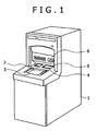
- FIG. 1 shows an external view of the ATM.
- An ATM 1 has a display unit 2 for displaying guidance to users, a manipulating unit 3 for receiving manipulation inputs by way of buttons or a touch panel in accordance with a guidance display on the display unit 2, and a cash slot 4 for accepting bill deposits and delivering payable bills.
- a customer-owned cash card is inserted into a card/slip processing mechanism 6, wherein card processing and transaction processing take place.
- a shutter 5 is arranged above the cash slot 4. The customer puts bills within the shutter 5 when depositing money, or takes out bills discharged inside the shutter 5 when withdrawing money.
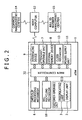
- Fig. 2 is a control block diagram of the ATM.
- a customer-operable unit having the aforementioned display unit 2 and manipulating unit 3, the card/slip processing mechanism 6 and a paper money recycling mechanism 10 are connected to a main controller 32, and necessary operations are performed under the control of the main controller 32.
- the main controller 32 is also connected to an attendant-operable unit 7, an external memory device (HDD) 8, an interfacing device 9 and a clock mechanism 13, and transfers necessary data to and from these units.
- the main controller 32 has a processor and a memory to process and store various data regarding cash transactions.
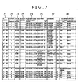
- a bill management table 70 shown in Fig. 7 a bill management table 80 whose contents are classified by the storing position shown in Fig. 8 , and a registration-sequenced bill information table 90 shown in Fig. 9 are stored in the external memory device 8.
- the bill management table 70 management information regarding bills is registered with the ID numbers of bills being used as the keys.
- the ID numbers of bills stored in each bill storing box are registered. Items of bill information registered in the bill management table 70 are acquired, rearranged in the order of ID numbers and registered in the registration-sequenced bill information table 90 in that rearranged order.
- the clock mechanism 13 which is a calendar clock keeping time by the year, month, day, hour, minute and second, informs the main controller 32 of the time of each transaction of depositing, withdrawing or the like by a customer.
- a power supply unit 11 supplies electric power to the main controller 32, the aforementioned mechanisms and constituent parts.
- the interfacing device 9 is connected to and exchanges necessary data with a host computer 12 installed at the computation center of the financial institution.
- the format of the telegraphs exchanged between the ATM 1 and the host computer 12 includes such items of information as the financial institution number, branch number, apparatus type, apparatus number, account type, account number, password, transaction type and sum as shown in Fig. 10 .
- the host computer 12 is equipped with a large-capacity memory device for managing information on customers' accounts.
- the host computer 12 is also connected to a management center 14 jointly managed by a plurality of financial institutions and a bill ID number management center 15 established at the Bank of Japan.
- a management center 14 jointly managed by a plurality of financial institutions and a bill ID number management center 15 established at the Bank of Japan.
- information on bills collected from the host computers 12 of financial institutions is managed with the ID numbers of bills being used as the keys.
- the ID number 71 has a position in sequence 72, a transaction type 73, an account number 74, a time 75, a bill feed source 76, a bill store destination 77 and a validation result 78 are registered in the bill management table 70.
- the position in sequence 72 means the position in the sequence of bill handling; position 1, for instance, is a mode in which the attendant of the financial institution or somebody else inserts a cassette 22 into the ATM and loads a storing box with bills in the cassette. Since no transaction by any customer is involved in this mode, no account number is registered. It concerns a state of management in which true ⁇ 1000 real notes have been transferred from the cassette in the bill feed source 76 to a ⁇ 1000 box in the bill store destination 77.
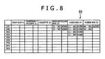
- the storing position-based bill management table 80 successively memorizes and holds the ID numbers of bills, classified by the location in which they are stored, namely a non-recycling box 23, ⁇ 1000 box 24 or a ⁇ 10000 box 25. Since this storing position-based bill management table 80 dynamically manages bills, keeping the increase or decrease of bills on a real time basis, the ID numbers of bills delivered out and discharged from the ⁇ 1000 box 24 and the ⁇ 10000 box 25, both of which are recycling boxes, are erased.
- the registration-sequenced bill information table 90 is prepared by rearranging under the control of the main controller 32 the contents of the bill management table 70 shown in Fig. 7 into the order of ID numbers of bills with the ID number being used as the keys. It is preferable for the updating of the registration-sequenced bill information table 90 to be processed with reference to the bill management table 70 on a real time basis every time one transaction has been completed.
- Fig. 3 shows the configuration of the bill recycling mechanism (BRM) 10.
- the BRM 10 is a mechanism for handling bills within the ATM 1; in the illustration, the right hand side is toward the user.
- An intermediate plate 28 is disposed within the cash slot 4 to partition the slot into an in-portion and an out-portion.
- a discriminator 20 for identifying the denominations of ⁇ 1000, ⁇ 10000 and other bills and performing true/false determination of bills; a temporary stocker 21 for temporarily holding bills having passed the discriminator 20 until the customer confirms the sum to be deposited; a non-recycling box 23 for storing ⁇ 5000 bills, which are not used for payment to customers, and too heavily damaged bills for recycling; the ⁇ 1000 box 24, the ⁇ 10000 box 25 for storing ⁇ 10000 bills and other units are linked to the conveying path 27 which is linked to the cash slot 4.
- bills are pinched between belts or rollers when they are conveyed over the conveying path 27, which is equipped, where required, with gates 26a through 26e for switching the direction of conveying the bills.
- the ⁇ 1000 box 24 and the ⁇ 10000 box 25 are collectively referred to as the recycling boxes.
- a cassette 22 for loading the recycling boxes with bills and holding the bills picked up by the attendant from the recycling boxes to be carried away.
- the discriminator 20 is provided with a surface information reader 29 for optically or magnetically reading surface information, such as patterns and characters, on the surface of each bill to identify the denomination and perform true/false determination of bills and an IC reader 30 for reading ID information of the IC chip embedded in each bill.
- the IC reader 30 includes an antenna to be used for the transmission and reception mainly of electromagnetic waves and a signal processor for processing signals transmitted to or received from IC chips.
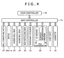
- Fig. 4 is a functional block diagram of the BRM 10.
- a BRM controller 31 is connected to the main controller 32, controls the BRM 10 in accordance with instructions from the main controller 32 and the detected state of the BRM 10, and transmits as required information on the BRM 10 to the main controller 32.
- the same elements as their counterparts in Figs. 2 and 3 are denoted by respectively the same reference signs, and their description will not be duplicated.
- a transaction selecting screen is displayed on the display unit 2.
- the customer manipulates the manipulating unit 3 to select "Deposit” and enters it (S01).
- the main controller 32 acquires the type of transaction selected by the customer, and stores it into a memory (not shown).
- the customer inserts a cash card into the medium slit of the card/slip processing mechanism 6 (S02).
- the card processing mechanism reads information stored in the card, namely information items including the customer's account number, and similarly stores that information into the memory of the main controller 32.
- the shutter 5 of the cash slot 4 opens (S04).
- a bill or bills are put into the in-portion (toward the customer) of the cash slot 4 (S05)
- bills are fed out to the conveying path 27 after the shutter 5 is closed (S06) and conveyed via the gate 26a to the discriminator 20 (S07).
- the bills first undergo reading of the ID numbers of their respective IC chips by the IC reader 30 (S08). Then, the surface information reader 29 reads such items of surface information as the patterns and characters printed on and the degree of magnetization and thickness of the bills to identify the denomination and perform true/false determination of the bills (S09).
- the BRM controller 31 successively transmits to the main controller 32 the items of ID information read by the IC reader 30. Since the BRM controller 31 can sense handling information on the bills, namely the situational factors of the bill bearing a given ID number, such as its feed source, position in the sequence of bills fed from that source, destination and position in the sequence of bills stored into that destination, the main controller 32 successively collects such bill management information.
- the main controller 32 then puts together information on the state of the bills, including the type of transaction selected by the customer and the customer's account number, with the ID numbers of bills collected from the BRM controller 31 being used as the keys, and registers it as new management information in the bill management table 70 ( Fig. 7 ) stored in the external memory device 8 (S10).
- the total sum of the bills found true is displayed on the display unit 2, and a confirmation input by the customer through the manipulating unit 3 is awaited (S14).
- the contents of the bill management table 70 then are a group of data in the state of position 2 in Fig. 7 .
- the main controller 32 will transmit transaction information to the host computer 12 via the interfacing device 9 to update the balance of the customer's pertinent account (S16). On this occasion, it acquires the customer's transaction time.
- bills held in the temporary stocker 21 are fed out to the conveying path 27 via the gate 26b, and conveyed to the discriminator 20 (S18).
- Each bill passing the discriminator 20 first undergoes reading of its surface information by the surface information reader 29, and its denomination and validity are determined (S19). Then the ID number of its IC chip is read by the IC reader 30, and this ID number, together with information on the result of discrimination of the bill, is transferred to the main controller 32 to be stored into the bill management table 70 in the external memory device 8 (S20).
- Bills are classified by the denomination and the result of true/false determination (S21), and stored into corresponding storing boxes.
- ⁇ 1000 bills are stored into the ⁇ 1000 box 24 and ⁇ 10000 bills, into the ⁇ 10000 box 25 (S23). Since ⁇ 2000 and ⁇ 5000 bills are not used for payment to customers, they are collected into the non-recycling box 23 (S22).
- the contents of the bill management table at the time of this storing are in the state of position 3 in the management table shown in Fig. 7 .
- the ⁇ 10000 bill of ID No. AA--002 though it is found dubious in the discrimination procedure, is found true in the second block of deposition, with its ID number being read too, and therefore deemed true to be stored into the ⁇ 10000 box 25.
- the setting can be altered for more strict management of the state of bills to collect any bill once found dubious into the non-recycling box 23.
- the main controller 32 is aware of the state of each bill when it is finally stored into a storing box, the contents of the storing position-based bill management table 80 are also updated on this occasion.
- the customer's cash card and a transaction slip is discharged from the medium slit of the card/slip processing mechanism 6 (S24), and the customer receives them to end the sequence of transaction.
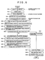
- Fig. 6 is a flowchart of paper money handling in a withdrawing transaction by another customer.
- the customer manipulates the manipulating unit 3 to select "Withdraw” (S51) and then inserts his or her cash card (S52).
- the customer enters a password into the manipulating unit 3 (S53) and then inputs the sum to be withdrawn (S54).
- the transaction information acquired in this way is transmitted from the ATM 1 to the host computer 12, and communication with the center thus takes place between the ATM 1 and the host computer 12 (S55).
- the host computer 12 confirms the identity of the customer by checking the entered password, updates the account balance, and transmits a payment permit to the ATM 1.
- the ATM 1 receives the payment permit, the BRM 10 successively feeds out bills in the amount of requested withdrawal from recycling boxes to the conveying path 27 (S56).
- Each bill passing the discriminator 20 first undergoes reading of the ID number of its IC chip by the IC reader 30 (S57). Then, the surface information reader 29 reads such items of surface information as the patterns and characters printed on and the degree of magnetization and thickness of the bills to identify the denomination and perform true/false determination of the bills (S58). The bill information acquired in this way is stored under the control of the main controller 32 into the bill management table 70 with the ID numbers of bills being used as the keys (S59).
- the bills in the temporary stocker 21 are fed out onto the conveying path 27 via the gate 26b and conveyed to the discriminator 20 (S63).
- Each bill passing the discriminator 20 undergoes reading of surface information by the surface information reader 29 to be determined whether it is true or false (S64).
- the IC reader 30 reads the ID number of its IC chip, and these items of bill information are stored into the bill management table 70 with the ID number as the key (S65), and the bills are stored into the non-recycling box 23 (S66).
- the contents of the bill management table 70 at this point of time are in the state of position 4 in the table shown in Fig. 7 .
- the ⁇ 1000 bill of ID number 11--004 though found "Inclination abnormal" because of its poor fed-out state, is found true also in storing for deposition, with its ID number being accurately read too, and therefore deemed to be a true ⁇ 1000 bill to be conveyed to the out-portion of the cash slot 4.
- the ID number of any bill fails to be read, it is also possible to infer the ID number of this bill from information on the bills stored immediately before and after this one by referencing the bill management table 70 of Fig. 7 , and restore its ID number. For instance, since bills stored into a recycling box are fed out in an order reverse to that of their storing, even if the ID number of any one bill fails to be read when it is to be paid out or this bill fails to be discriminated accurately, it is possible to restore the bill information which has failed to be read accurately by referencing the bill management table 70 and acquiring information on the bill at the time it was accepted and stored.
- the shutter 5 of the cash slot 4 is opened (S67), enabling the customer to receive the bills to be withdrawn (S68). After that, his or her cash card and a slip are discharged from the ATM 1 (S69), which the customer receives to end the sequence of transaction.
- the whereabouts of any bill can be found out by referencing this table 90.
- the source of a bill bearing a certain ID number i.e. the account number of the customer who deposited it, and its destination, the account number of the customer who withdrew it can be known.
- the attendant-operable unit 7 of the ATM 1 is also equipped with a display unit and a manipulating unit for inputting to be used by the attendant, similar to those of the customer-operable unit.
- the attendant-operable unit 7 and the main controller 32 serve here as information searching means.
- the registration-sequenced bill information table 90 it is possible to keep trace of any illicit act by the attendant of the financial institution by utilizing the registration-sequenced bill information table 90. If, for instance, the attendant is to manipulate the attendant-operable unit 7, he or she is required to enter a password for the attendant's exclusive use. This exclusive password and the time of manipulation by the attendant are registered in the external memory device 8 as logs. By collating this log information with the contents of the registration-sequenced bill information table 90, any bill inadvertently picked up by the attendant from anywhere in the ATM can also be kept trace of.
- a management center 15 equipped with a database for managing paper money ID numbers at the Bank of Japan, the issuing source of bills, and to collect similar information to what was described above at this center 15.
- Such a system would make possible true/false discrimination and keeping trace of bills by making inquiries by the ID number and moreover to establish a system of bill tracing and security on a nationwide scale.
- the results of bill validation are cumulatively stored with the ID number of the IC chips of bills being used as the key every time a bill moves in the ATM, the accuracy (reliability) of bill validation is enhanced. Even if the results of identifying the denomination at different times differ, the bill concerned will be collected into the non-recycling box, and accordingly wrong discrimination can be prevented.
- any such a bill in the ATM can be located or its owner identified and confirmed by searching the tables 70, 80 and 90 by using the ID number of the bill used as the key, resulting in enhanced security.
- the tables 70, 80 and 90 in this embodiment are described to be stored in the external memory device 8 within the ATM 1.
- DB database
- the server Since bill-related information is transmitted from a plurality of ATMs installed in each branch to the server, the server has to register the machine number of the ATM which has handled each bill correspondingly to the ID number of the bill in addition to the contents of the tables 70, 80 and 90.
- Searching of bill-related data stored in the DB of the server is accomplished by the attendant using a personal computer (PC). In this sense, the PC serves as information searching means. Incidentally, bill-related are transmitted to the host computer 14 from this server.
- PC personal computer
- paper money sheets in the apparatus can be accurately located and their movements readily kept trace of on the basis of distinguishing information held by IC chips.
- an apparatus handling bills for instance by storing in memory means discriminative information based on surface information on bills and discriminative information held by IC chips matched with each other, even where discriminative information based on bill surface information cannot be normally acquired, the bills can be smoothly and effectively handled by utilizing the discriminative information held by IC chips.
- the bill searched for can be detected by searching the contents of the memory means. Any non-real paper money sheet or the like can also be kept trace of by using discriminative information held by IC chips as the key.
Description
- The present invention relates to a paper money handling apparatus, and more particularly to management of securities such as bills, including validation of true securities against false ones and protection from illicit use by applying IC chips. It relates to, for instance, a managing method and system for bills in which wireless IC chips are embedded to be handled by automatic teller machines (ATMs).
- It is proposed to embed IC chips in bills, gift certificates and securities such as share certificates, so that stolen securities can be prevented from subsequent illicit use or effectively managing the reuse of securities, if recovered, by their legitimate managers by managing information, unique to each such security, stored in the IC chips.
- For instance, Patent Reference 1 (Japanese Published Unexamined Patent Application No.
2001-260580 JP 2001260580 - Patent Reference 2 (Japanese Published Unexamined Patent Application No.
2003-178185 JP 2003178185 - Patent Reference 3 (Japanese Published Unexamined Patent Application No.
2004-164156 JP 2004164156 - No such bill provided with an IC chip as the ones disclosed in the references cited above is in circulation as yet. Any ATM in current use discerns the trueness or falseness of paper money by detecting the dimensions and optical or magnetic characteristics of each sheet, and the management of bills seems to be relying on information on the results of such true/false tests and reference numbers of bills.
- To focus on the serial numbers of Bank of Japan notes, for instance, such a number is printed only on the front face of each bill, and its position differs from one denomination to another. Since bills are usually folded and kept in their bearer's wallet, they are likely to be creased. In order for an ATM to optically read surface information on a creased bill, it is necessary to smoothen the bill and perform sophisticated convey control involving accurate keeping of the bill's positional relationship with an optical sensor reading it.
- Moreover, as the background of the serial number includes a clearly printed portrait and pattern, reading the serial number of alphabetic letters and numerals isolated from the rest of the read image of the bill requires a color sensor of a high reading resolution, sophisticated image processing techniques and character reading techniques.
- Incidentally, more than 10 billion Bank of Japan notes are in circulation, and the effective life of each note is estimated at one to two years. Moreover, since the serial number consists of only nine letters and numerals, the same serial number is shared by more than one bill, and therefore the number is printed in different colors for further discrimination. On account of this circumstance, it is very difficult to read the serial number and to discriminate and manage bills by the serial number, and accordingly this technology does not seem to be available for practical use as yet.
- In the management of bills by an ATM for instance, it is attempted to assign a virtual serial number to each transaction of a customer, assign another sequence of virtual serial numbers to bills in the order of conveying them from the cash slot to the conveying path, store the denominations and true/false test results of bills obtained from the bill discriminator into a memory with these virtual serial numbers as keys, and store good bills into a temporary stocker or reject false or otherwise unacceptable bills back to the cash slot.
- However, these serial numbers assigned to bills are virtual numbers only for temporary use while the bills are conveyed within the ATM, and the bank attendant cannot visually recognize such serial numbers of bills having passed the ATM in his or her charge. Moreover, if bills become jammed during their conveyance and the attendant extracts the jammed bills, this will constitute a factor of uncertainty, which ruins the precondition of assigning the virtual serialnumbers. For this reason, it is diff icult to uniquely identify each individual bank note in the ATM.
-
US 2004/0039479 A1 discloses an apparatus for processing sheet material, in particular bank notes, comprising a processing device having at least one means for generating information on the processing of individual sheets of sheet material, and a monitoring device. The processing device has at least one means for detecting the identity of individual sheets and the monitoring device includes at least one memory device for storing information on the processing of individual sheets together with the identity of the individual sheets. The storage of information on processing together with the identity of individual sheets obtains a unique association of a processed individual sheet with the information generated during processing of said sheet, for example data on authenticity or fitness testing, sorting, demonetizing or destruction. In the case of disturbances or other processing problems, it can be determined from the totality or at least part of the information stored on the processing of individual sheets in what way processing was effected on individual sheets, in particular which sheets were sorted and output to which output pockets or which sheets were actually demonetized or destroyed. This permits the course of processing to be reconstructed completely or at least partly. The identity of individual sheets is preferably given by image data of the particular sheets. This is, for example, a picture of a printed sheet taken by a CCD camera. Additionally or alternatively, in particular in the case of bank notes, the identity of a sheet can be given by its serial number. Acquisition of the image data and/or serial number permits the identity of a printed sheet or bank note to be uniquely detected. A related apparatus is disclosed inDE 101 07 344 A1 . Both those apparatus identify bills by the serial numbers printed thereon. - It is an object of the invention to provide a bill handling apparatus and method which can accurately trace and manage the location of paper money.
- This object is solved by the apparatus of
claim 1 and the method ofclaim 5. The dependent claims relate to preferred embodiments of the invention. - A preferred embodiment of the present invention will now be described in conjunction with the accompanying drawings, in which:
-
Fig. 1 shows an external view of a commonly known ATM; -
Fig. 2 is a control block diagram of an ATM in a preferred embodiment of the invention; -
Fig. 3 is a profile of a papermoney recycling mechanism 10 in the preferred embodiment of the invention; -
Fig. 4 is a functional block diagram of the papermoney recycling mechanism 10 in the embodiment; -
Fig. 5 is a flowchart of paper money handling in a depositing transaction in the embodiment; -
Fig. 6 is a flowchart of paper money handling in a withdrawing transaction in the embodiment; -
Fig. 7 shows a bill management table 70 in which the state of paper money management is to be registered in the embodiment; -
Fig. 8 shows a bill management table 80 whose contents are classified by the storing position in the embodiment; -
Fig. 9 shows a registration-sequenced bill information table 90 in the embodiment in which the sequence is in the order of registration; and -
Fig. 10 shows an example of telegraph between an ATM and a host computer in the embodiment. - A preferred embodiment of the present invention will be described in detail below with reference to the accompanying drawings.
- Whereas paper money sheets in the context of the invention include bills, promissory notes, checks, share certificates, bonds and gift certificates, the following description will refer, by way of example, to bills handled by financial institutions equipped with ATMs. An ATM is usually equipped with a bill recycling mechanism (BRM), which accepts bills deposited into the ATM and uses them to respond to withdrawing transactions by customers.
- This embodiment uses bills each of which has, embedded in one of its corners, a wireless IC chip having unique identifying information (ID number). The number of digits of information recorded on the IC chip is, for instance, 128. The information to identify a bill may include unique items such as its issuing country, denomination, version number (new or old), the production number at the printing bureau, and the history of changes in production. It is not necessary to use all the 128 digits, some of which may remain unused. The ID number of the IC chip is read by a wireless IC reader disposed somewhere on the conveying path, for instance the bill discriminator of the ATM.
-
Fig. 1 shows an external view of the ATM. AnATM 1 has adisplay unit 2 for displaying guidance to users, a manipulatingunit 3 for receiving manipulation inputs by way of buttons or a touch panel in accordance with a guidance display on thedisplay unit 2, and acash slot 4 for accepting bill deposits and delivering payable bills. In a cash transaction, a customer-owned cash card is inserted into a card/slip processing mechanism 6, wherein card processing and transaction processing take place. Ashutter 5 is arranged above thecash slot 4. The customer puts bills within theshutter 5 when depositing money, or takes out bills discharged inside theshutter 5 when withdrawing money. -
Fig. 2 is a control block diagram of the ATM. In theATM 1, a customer-operable unit having theaforementioned display unit 2 and manipulatingunit 3, the card/slip processing mechanism 6 and a papermoney recycling mechanism 10 are connected to amain controller 32, and necessary operations are performed under the control of themain controller 32. Themain controller 32 is also connected to an attendant-operable unit 7, an external memory device (HDD) 8, aninterfacing device 9 and aclock mechanism 13, and transfers necessary data to and from these units. Though not shown, themain controller 32 has a processor and a memory to process and store various data regarding cash transactions. - As will be described in more detail afterwards, a bill management table 70 shown in
Fig. 7 , a bill management table 80 whose contents are classified by the storing position shown inFig. 8 , and a registration-sequenced bill information table 90 shown inFig. 9 are stored in theexternal memory device 8. - In the bill management table 70, management information regarding bills is registered with the ID numbers of bills being used as the keys. In the storing position-based bill management table 80, the ID numbers of bills stored in each bill storing box are registered. Items of bill information registered in the bill management table 70 are acquired, rearranged in the order of ID numbers and registered in the registration-sequenced bill information table 90 in that rearranged order.
- The
clock mechanism 13, which is a calendar clock keeping time by the year, month, day, hour, minute and second, informs themain controller 32 of the time of each transaction of depositing, withdrawing or the like by a customer. Apower supply unit 11 supplies electric power to themain controller 32, the aforementioned mechanisms and constituent parts. Theinterfacing device 9 is connected to and exchanges necessary data with ahost computer 12 installed at the computation center of the financial institution. The format of the telegraphs exchanged between theATM 1 and thehost computer 12 includes such items of information as the financial institution number, branch number, apparatus type, apparatus number, account type, account number, password, transaction type and sum as shown inFig. 10 . - The
host computer 12 is equipped with a large-capacity memory device for managing information on customers' accounts. Thehost computer 12 is also connected to amanagement center 14 jointly managed by a plurality of financial institutions and a bill IDnumber management center 15 established at the Bank of Japan. At bothcenters host computers 12 of financial institutions is managed with the ID numbers of bills being used as the keys. - Now, the configuration of the bill management table 70 will be described with reference to
Fig. 7 . For the IC chip of each bill, theID number 71 has a position insequence 72, atransaction type 73, anaccount number 74, atime 75, abill feed source 76, abill store destination 77 and avalidation result 78 are registered in the bill management table 70. The position insequence 72 means the position in the sequence of bill handling;position 1, for instance, is a mode in which the attendant of the financial institution or somebody else inserts acassette 22 into the ATM and loads a storing box with bills in the cassette. Since no transaction by any customer is involved in this mode, no account number is registered. It concerns a state of management in which true ¥1000 real notes have been transferred from the cassette in thebill feed source 76 to a ¥1000 box in thebill store destination 77. - In
position 2, a customer whose account number is 123456 has deposited a total of six bills, of which five are in a temporary stocker and the remaining one (having an ID number of "R0--001") has been rejected to the cash slot. Inposition 3, the five bills held in the temporary stocker are stored in a non-recycling box, the ¥1000 box and a ¥10000 box. Inposition 4, another customer whose account number is 456789 has with drawn bills in a sum of ¥14,000. Time information on the state of each bill is also registered. - Next, referring to
Fig. 8 , the storing position-based bill management table 80 successively memorizes and holds the ID numbers of bills, classified by the location in which they are stored, namely anon-recycling box 23, ¥1000box 24 or a ¥10000box 25. Since this storing position-based bill management table 80 dynamically manages bills, keeping the increase or decrease of bills on a real time basis, the ID numbers of bills delivered out and discharged from the ¥1000box 24 and the ¥10000box 25, both of which are recycling boxes, are erased. - As shown in
Fig. 9 , the registration-sequenced bill information table 90 is prepared by rearranging under the control of themain controller 32 the contents of the bill management table 70 shown inFig. 7 into the order of ID numbers of bills with the ID number being used as the keys. It is preferable for the updating of the registration-sequenced bill information table 90 to be processed with reference to the bill management table 70 on a real time basis every time one transaction has been completed. -
Fig. 3 shows the configuration of the bill recycling mechanism (BRM) 10. TheBRM 10 is a mechanism for handling bills within theATM 1; in the illustration, the right hand side is toward the user. Anintermediate plate 28 is disposed within thecash slot 4 to partition the slot into an in-portion and an out-portion. - A
discriminator 20 for identifying the denominations of ¥1000, ¥10000 and other bills and performing true/false determination of bills; atemporary stocker 21 for temporarily holding bills having passed thediscriminator 20 until the customer confirms the sum to be deposited; anon-recycling box 23 for storing ¥5000 bills, which are not used for payment to customers, and too heavily damaged bills for recycling; the ¥1000box 24, the ¥10000box 25 for storing ¥10000 bills and other units are linked to the conveyingpath 27 which is linked to thecash slot 4. Incidentally, bills are pinched between belts or rollers when they are conveyed over the conveyingpath 27, which is equipped, where required, withgates 26a through 26e for switching the direction of conveying the bills. - The ¥1000
box 24 and the ¥10000box 25 are collectively referred to as the recycling boxes. There also is mounted acassette 22 for loading the recycling boxes with bills and holding the bills picked up by the attendant from the recycling boxes to be carried away. - The
discriminator 20 is provided with asurface information reader 29 for optically or magnetically reading surface information, such as patterns and characters, on the surface of each bill to identify the denomination and perform true/false determination of bills and anIC reader 30 for reading ID information of the IC chip embedded in each bill. TheIC reader 30 includes an antenna to be used for the transmission and reception mainly of electromagnetic waves and a signal processor for processing signals transmitted to or received from IC chips. -
Fig. 4 is a functional block diagram of theBRM 10. ABRM controller 31 is connected to themain controller 32, controls theBRM 10 in accordance with instructions from themain controller 32 and the detected state of theBRM 10, and transmits as required information on theBRM 10 to themain controller 32. The same elements as their counterparts inFigs. 2 and3 are denoted by respectively the same reference signs, and their description will not be duplicated. - Next, the operations to handle bills that are deposited will be described with reference to the flowchart in
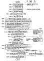
Fig. 5 . - When the
ATM 1 detects the approach of a customer, a transaction selecting screen is displayed on thedisplay unit 2. Looking at the transaction selecting screen, the customer manipulates the manipulatingunit 3 to select "Deposit" and enters it (S01). Then, themain controller 32 acquires the type of transaction selected by the customer, and stores it into a memory (not shown). Next the customer inserts a cash card into the medium slit of the card/slip processing mechanism 6 (S02). Then, the card processing mechanism reads information stored in the card, namely information items including the customer's account number, and similarly stores that information into the memory of themain controller 32. - When the customer enters a password into the manipulating unit 3 (S03), the
shutter 5 of thecash slot 4 opens (S04). When a bill or bills are put into the in-portion (toward the customer) of the cash slot 4 (S05), bills are fed out to the conveyingpath 27 after theshutter 5 is closed (S06) and conveyed via thegate 26a to the discriminator 20 (S07). - Having arrived at the
discriminator 20, the bills first undergo reading of the ID numbers of their respective IC chips by the IC reader 30 (S08). Then, thesurface information reader 29 reads such items of surface information as the patterns and characters printed on and the degree of magnetization and thickness of the bills to identify the denomination and perform true/false determination of the bills (S09). - Then the
BRM controller 31 successively transmits to themain controller 32 the items of ID information read by theIC reader 30. Since theBRM controller 31 can sense handling information on the bills, namely the situational factors of the bill bearing a given ID number, such as its feed source, position in the sequence of bills fed from that source, destination and position in the sequence of bills stored into that destination, themain controller 32 successively collects such bill management information. - The
main controller 32 then puts together information on the state of the bills, including the type of transaction selected by the customer and the customer's account number, with the ID numbers of bills collected from theBRM controller 31 being used as the keys, and registers it as new management information in the bill management table 70 (Fig. 7 ) stored in the external memory device 8 (S10). - If a given bill is found false as a result of determination by the
bill discriminator 20 according to surface information (No at S11), that bill is conveyed to the out-portion of thecash slot 4 via thegate 26b and returned to the customer (S13). Or any bill found true as a result of determination according to surface information (Yes at S11) is conveyed to and stored into the temporary stocker 21 (S12). - When every bill entered into the
cash slot 4 has gone through the validation procedure in this way, the total sum of the bills found true is displayed on thedisplay unit 2, and a confirmation input by the customer through the manipulatingunit 3 is awaited (S14). The contents of the bill management table 70 then are a group of data in the state ofposition 2 inFig. 7 . - Now, if in the action to check the deposited sum the customer does not approve of the sum (No at S15), all the bills held in the
temporary stocker 21 will be conveyed to the out-portion of thecash slot 4 and returned to the customer (S17). Or if the customer inputs confirmation (Yes at S16), themain controller 32 will transmit transaction information to thehost computer 12 via theinterfacing device 9 to update the balance of the customer's pertinent account (S16). On this occasion, it acquires the customer's transaction time. - Next, bills held in the
temporary stocker 21 are fed out to the conveyingpath 27 via thegate 26b, and conveyed to the discriminator 20 (S18). Each bill passing thediscriminator 20 first undergoes reading of its surface information by thesurface information reader 29, and its denomination and validity are determined (S19). Then the ID number of its IC chip is read by theIC reader 30, and this ID number, together with information on the result of discrimination of the bill, is transferred to themain controller 32 to be stored into the bill management table 70 in the external memory device 8 (S20). - Bills are classified by the denomination and the result of true/false determination (S21), and stored into corresponding storing boxes. Thus, ¥1000 bills are stored into the ¥1000
box 24 and ¥10000 bills, into the ¥10000 box 25 (S23). Since ¥2000 and ¥5000 bills are not used for payment to customers, they are collected into the non-recycling box 23 (S22). - The contents of the bill management table at the time of this storing are in the state of
position 3 in the management table shown inFig. 7 . For instance, the ¥10000 bill of ID No. AA--002, though it is found dubious in the discrimination procedure, is found true in the second block of deposition, with its ID number being read too, and therefore deemed true to be stored into the ¥10000box 25. Incidentally, there is no need to limit discrimination to this procedure, but the setting can be altered for more strict management of the state of bills to collect any bill once found dubious into thenon-recycling box 23. - Further, since the
main controller 32 is aware of the state of each bill when it is finally stored into a storing box, the contents of the storing position-based bill management table 80 are also updated on this occasion. Upon completion of data processing for a transaction with any customer, finally the customer's cash card and a transaction slip is discharged from the medium slit of the card/slip processing mechanism 6 (S24), and the customer receives them to end the sequence of transaction. -
Fig. 6 is a flowchart of paper money handling in a withdrawing transaction by another customer. The customer manipulates the manipulatingunit 3 to select "Withdraw" (S51) and then inserts his or her cash card (S52). Next, the customer enters a password into the manipulating unit 3 (S53) and then inputs the sum to be withdrawn (S54). The transaction information acquired in this way is transmitted from theATM 1 to thehost computer 12, and communication with the center thus takes place between theATM 1 and the host computer 12 (S55). - The
host computer 12 confirms the identity of the customer by checking the entered password, updates the account balance, and transmits a payment permit to theATM 1. When theATM 1 receives the payment permit, theBRM 10 successively feeds out bills in the amount of requested withdrawal from recycling boxes to the conveying path 27 (S56). - Each bill passing the
discriminator 20 first undergoes reading of the ID number of its IC chip by the IC reader 30 (S57). Then, thesurface information reader 29 reads such items of surface information as the patterns and characters printed on and the degree of magnetization and thickness of the bills to identify the denomination and perform true/false determination of the bills (S58). The bill information acquired in this way is stored under the control of themain controller 32 into the bill management table 70 with the ID numbers of bills being used as the keys (S59). - Any bill found false as a result of determination (No at S60) is stored into the
temporary stocker 21 via thegate 26b (S61). Or any bill found true as a result of discrimination (Yes at S60) is conveyed to thecash slot 4 and held there (S62). - When the bills discharged reach the sum to be withdrawn, the bills in the
temporary stocker 21 are fed out onto the conveyingpath 27 via thegate 26b and conveyed to the discriminator 20 (S63). Each bill passing thediscriminator 20 undergoes reading of surface information by thesurface information reader 29 to be determined whether it is true or false (S64). Then theIC reader 30 reads the ID number of its IC chip, and these items of bill information are stored into the bill management table 70 with the ID number as the key (S65), and the bills are stored into the non-recycling box 23 (S66). - The contents of the bill management table 70 at this point of time are in the state of
position 4 in the table shown inFig. 7 . Out of the bills in the state ofposition 4, the ¥1000 bill ofID number 11--004, though found "Inclination abnormal" because of its poor fed-out state, is found true also in storing for deposition, with its ID number being accurately read too, and therefore deemed to be a true ¥1000 bill to be conveyed to the out-portion of thecash slot 4. Incidentally, there is no need to limit discrimination to this procedure, but the setting can be altered for more strict management of the state of bills to collect any bill found abnormal in conveyance into thenon-recycling box 23. - Further, even if the ID number of any bill fails to be read, it is also possible to infer the ID number of this bill from information on the bills stored immediately before and after this one by referencing the bill management table 70 of
Fig. 7 , and restore its ID number. For instance, since bills stored into a recycling box are fed out in an order reverse to that of their storing, even if the ID number of any one bill fails to be read when it is to be paid out or this bill fails to be discriminated accurately, it is possible to restore the bill information which has failed to be read accurately by referencing the bill management table 70 and acquiring information on the bill at the time it was accepted and stored. - When all the bills in the
temporary stocker 21 have been stored into thenon-recycling box 23, theshutter 5 of thecash slot 4 is opened (S67), enabling the customer to receive the bills to be withdrawn (S68). After that, his or her cash card and a slip are discharged from the ATM 1 (S69), which the customer receives to end the sequence of transaction. - To add, as the contents of the bill management table 70 are referenced and those of the registration-sequenced bill information table 90 are updated every time the processing of one transaction is ended, the whereabouts of any bill can be found out by referencing this table 90. For instance, the source of a bill bearing a certain ID number, i.e. the account number of the customer who deposited it, and its destination, the account number of the customer who withdrew it can be known. This is also true of any bill stored in a non-recycling box. The attendant-operable unit 7 of the
ATM 1 is also equipped with a display unit and a manipulating unit for inputting to be used by the attendant, similar to those of the customer-operable unit. Therefore, it is possible to uniquely identify any bill to be identified by searching the bill management table 70, the registration-sequenced bill information table 90 or the like with the ID number of the bill being used as the key at an instruction from the attendant-operable unit 7. Thus, the attendant-operable unit 7 and themain controller 32 serve here as information searching means. - Also, it is possible to keep trace of any illicit act by the attendant of the financial institution by utilizing the registration-sequenced bill information table 90. If, for instance, the attendant is to manipulate the attendant-operable unit 7, he or she is required to enter a password for the attendant's exclusive use. This exclusive password and the time of manipulation by the attendant are registered in the
external memory device 8 as logs. By collating this log information with the contents of the registration-sequenced bill information table 90, any bill inadvertently picked up by the attendant from anywhere in the ATM can also be kept trace of. - It is also possible to extract, under the control of the
main controller 32, the financial institution number, branch number, machine type and machine number out of information constituting the telegraph of communication shown inFig. 10 , add information matching each ID number in the registration-sequenced bill information table 90 with these items of information as header information, and transmit them from theATM 1 to thehost computer 12 to enable these items of bill information to be collectively managed in the database DB with which thehost computer 12 of the financial institution is provided. - Also, by transmitting similar items of information to the
management center 14 jointly used by different financial institutions and storing them collectively in its database, bills in their circulation process can be kept trace of among these financial institutions. - It is further possible to establish a
management center 15 equipped with a database for managing paper money ID numbers at the Bank of Japan, the issuing source of bills, and to collect similar information to what was described above at thiscenter 15. Such a system would make possible true/false discrimination and keeping trace of bills by making inquiries by the ID number and moreover to establish a system of bill tracing and security on a nationwide scale. - As hitherto described, in this embodiment of the invention, even if bills determined by the discriminator at the time of loading the cassette or when the bills are deposited and stored into a recycling box are later found impossible, when they are to be paid out, to be identified in denomination or determined to be true or false on account of failure to normally acquire discriminative information based on the bills' surface information, affected by such conveyance factors as abnormal inclination or spacing, it is still possible, if the ID numbers of their IC chips can be read, to identify their denomination and number by reading discriminative information acquired at the time of their depositing or loading stored in the bill management table 70 or the table 90. As a result, bills which would have been collected into the non-recycling box on account of impossibility to identify their denominations or to determine them to be true or false by the conventional technique can still be used for payment if this embodiment allows their normal discrimination according to the ID numbers. Therefore, the number of bills unsuitable for recycling can be significantly reduced, with a corresponding improvement in the efficiency of fund utilization.
- Also, as the results of bill validation are cumulatively stored with the ID number of the IC chips of bills being used as the key every time a bill moves in the ATM, the accuracy (reliability) of bill validation is enhanced. Even if the results of identifying the denomination at different times differ, the bill concerned will be collected into the non-recycling box, and accordingly wrong discrimination can be prevented.
- Furthermore, even if the attendant illicitly picks up any bill from the ATM, the customer leaves behind withdrawn bills, or any bill remains in the cash slot undetected, any such a bill in the ATM can be located or its owner identified and confirmed by searching the tables 70, 80 and 90 by using the ID number of the bill used as the key, resulting in enhanced security.
- Although the present invention has been described so far with reference to a preferred embodiment thereof, the invention is not limited to this embodiment, but can be modified in many different ways.
- For instance, the tables 70, 80 and 90 in this embodiment are described to be stored in the
external memory device 8 within theATM 1. However, a modification is conceivable in which these tables are architected in the database (DB) of a server installed in each branch of the financial institution. Since bill-related information is transmitted from a plurality of ATMs installed in each branch to the server, the server has to register the machine number of the ATM which has handled each bill correspondingly to the ID number of the bill in addition to the contents of the tables 70, 80 and 90. Searching of bill-related data stored in the DB of the server is accomplished by the attendant using a personal computer (PC). In this sense, the PC serves as information searching means. Incidentally, bill-related are transmitted to thehost computer 14 from this server. - The definitions of terms or the names of elements in this embodiment constitute a mere example, but not the only possible definitions or names. This is true of the compositions and names of the tables, which could be otherwise than in this embodiment. These tables may as well be called databases and configured as such.
- According to the invention, paper money sheets in the apparatus can be accurately located and their movements readily kept trace of on the basis of distinguishing information held by IC chips. In an apparatus handling bills for instance, by storing in memory means discriminative information based on surface information on bills and discriminative information held by IC chips matched with each other, even where discriminative information based on bill surface information cannot be normally acquired, the bills can be smoothly and effectively handled by utilizing the discriminative information held by IC chips. Furthermore, even if any paper money sheet is illicitly picked up from the paper money handling apparatus, the bill searched for can be detected by searching the contents of the memory means. Any non-real paper money sheet or the like can also be kept trace of by using discriminative information held by IC chips as the key.
Claims (8)
- A bill handling apparatus comprising:a manipulation unit (3) for selecting the type of transaction to be done by a customer;a controller (32) for recognising the type of transaction selected with the manipulation unit;a conveying path (27) for conveying a bill;a bill discriminator (20, 29) for reading surface information from a bill conveyed over the conveying path and performing true/false determination of the bill;a memory unit (8, 70, 90) for storing information on a result of determination by the bill discriminator (20, 29) and information on the type of transaction by a customer recognised by the controller (32); anda wireless IC reader (30) provided for reading unique discriminative information held by an IC chip in the conveyed bill, whereinthe memory unit stores first and second bill management tables (70, 90),the first bill management table (70) registers said discriminative information, said information on the result of determination and the information on the type of transaction cumulatively each time a bill passes through the wireless IC reader (30) and the bill discriminator (20, 29), andthe second bill management table (90) registers said discriminative information, said information on the result of determination and said information on the type of transaction, from the first table, re-arranged in the order of the discriminative information so that the second bill management table can be searched for the registered information on the result of determination and information on the type of transaction with reference to the discriminative information.
- The bill handling apparatus of claim 1, comprising:an attendant-operable unit (7) to be operated by an attendant, whereinthe controller (32) is adapted to search in the first and/or second bill management table (70, 90) in accordance with an instruction from the attendant-operable unit.
- The bill handling apparatus of claim 1, wherein
the controller (32) is adapted to judge, in accordance with said discriminative information registered in the first and/or second bill management table (70, 90), whether a bill is to be dispensed when the bill cannot be determined as true or false by the bill discriminator (20, 29) during dispensing. - The bill handling apparatus of claim 1, wherein
said information on the type of transaction includes an account number of the customer. - A bill management method for use in a bill handling apparatus which handles bills each having an IC chip holding unique discriminative information, comprising the following steps:recognising the type of transaction to be done by a customer using the bill handling apparatus;conveying bills over a conveying path (27) for transactions with customers;reading, by a bill discriminator (20, 29) installed on the conveying path, surface information on the conveyed bills and performing true/false determination of the bills;reading with a wireless IC reader (30) the discriminative information held by the IC chips of the conveyed bills; andstoring into a memory unit (8) having first and second bill management tables (70, 90) information on a result of determination made by the bill discriminator, the discriminative information obtained by the IC reader and information on the recognised type of transaction, whereinthe first bill management table (70) registers said discriminative information, said information on the result of determination and the information on the type of transaction cumulatively each time a bill passes through the wireless IC reader (30) and the bill discriminator (20, 29), andthe second bill management table (90) registers said discriminative information, said information on the result of determination and said information on the type of transaction, from the first table, re-arranged in the order of the discriminative information so that the second bill management table can be searched for the registered information on the result of determination and information on the type of transaction with reference to the discriminative information.
- The method of claim 5, wherein:an account number acquired from a card used by the customer and information regarding the time when the transaction was done are stored, being matched with the discriminative information.
- The method of claim 5 or 6, further including an information searching step of searching for information stored in the memory unit (8) by using the discriminative information as a key.
- The method of any of Claims 5 to 6, further including a step of adding machine-specific information on the bill handling apparatus to information stored in the memory unit (8) and transmitting the resultant augmented information to a host computer (12, 14, 15) to which the bill handling apparatus is connected.
Applications Claiming Priority (1)
| Application Number | Priority Date | Filing Date | Title |
|---|---|---|---|
| JP2004255327A JP4528067B2 (en) | 2004-09-02 | 2004-09-02 | Bill handling device, bill management system, bill management method, and paper sheet handling device |
Publications (2)
| Publication Number | Publication Date |
|---|---|
| EP1632909A1 EP1632909A1 (en) | 2006-03-08 |
| EP1632909B1 true EP1632909B1 (en) | 2016-01-06 |
Family
ID=35198090
Family Applications (1)
| Application Number | Title | Priority Date | Filing Date |
|---|---|---|---|
| EP05011216.8A Expired - Fee Related EP1632909B1 (en) | 2004-09-02 | 2005-05-24 | Paper money handling machine |
Country Status (3)
| Country | Link |
|---|---|
| US (1) | US7458506B2 (en) |
| EP (1) | EP1632909B1 (en) |
| JP (1) | JP4528067B2 (en) |
Families Citing this family (35)
| Publication number | Priority date | Publication date | Assignee | Title |
|---|---|---|---|---|
| JP4580168B2 (en) * | 2001-08-30 | 2010-11-10 | 富士通株式会社 | Automatic money transaction equipment |
| JP4832026B2 (en) * | 2005-08-25 | 2011-12-07 | ローレル精機株式会社 | Banknote handling machine |
| WO2007061377A1 (en) * | 2005-11-24 | 2007-05-31 | Consensum As | Method for handling of a bank note and system therefore |
| JP5148087B2 (en) * | 2006-08-17 | 2013-02-20 | ローレル精機株式会社 | Banknote handling machine |
| JP4451891B2 (en) * | 2007-03-19 | 2010-04-14 | サンデン株式会社 | Electronic money deposit machine |
| CN101715590B (en) * | 2007-04-24 | 2013-05-01 | 塔雷瑞斯控股有限公司 | Method and apparatus for sorting articles |
| JP5156439B2 (en) * | 2008-03-12 | 2013-03-06 | 日立オムロンターミナルソリューションズ株式会社 | Banknote handling device and automatic cash transaction device |
| JP5150342B2 (en) * | 2008-04-14 | 2013-02-20 | 日立オムロンターミナルソリューションズ株式会社 | Banknote handling equipment |
| US8579191B2 (en) * | 2008-06-27 | 2013-11-12 | Diebold Self-Service Systems, Division Of Diebold, Incorporated | Automated banking system controlled responsive to data bearing records |
| US8181854B1 (en) | 2008-07-31 | 2012-05-22 | Bank Of America Corporation | Cash handling device having integrated wireless modem |
| US8025214B1 (en) | 2008-07-31 | 2011-09-27 | Bank Of America Corporation | Cash handling device having integrated controller |
| US8227936B1 (en) | 2008-07-31 | 2012-07-24 | Bank Of America Corporation | Cash handling device having integrated uninterruptible power supply |
| WO2010035346A1 (en) * | 2008-09-29 | 2010-04-01 | グローリー株式会社 | Banknote processing system and banknote processing method |
| KR101026151B1 (en) * | 2008-10-27 | 2011-04-05 | 노틸러스효성 주식회사 | ATM having Optical Character ReaderOCR function and high-denomination bill management using the same |
| DE102009035028A1 (en) * | 2009-07-28 | 2011-02-03 | Wincor Nixdorf International Gmbh | Banknote payout apparatus and method for determining the banknote stock of at least one banknote container of this apparatus |
| DE102010046115A1 (en) * | 2010-09-21 | 2012-03-22 | Giesecke & Devrient Gmbh | Method for monitoring the transport of banknotes |
| JP5614225B2 (en) | 2010-10-14 | 2014-10-29 | 沖電気工業株式会社 | Banknote deposit and withdrawal machine |
| KR101544095B1 (en) | 2010-10-19 | 2015-08-12 | 노틸러스효성 주식회사 | An ATM capable of scanning the serial number of banknote and the banknote management method using the same |
| CN102013128B (en) * | 2010-12-17 | 2012-10-31 | 广州广电运通金融电子股份有限公司 | Bill processing system and method |
| JP2012198764A (en) * | 2011-03-22 | 2012-10-18 | Glory Ltd | Money processor |
| JP5633456B2 (en) * | 2011-03-30 | 2014-12-03 | 沖電気工業株式会社 | Banknote deposit and withdrawal machine |
| JP5690668B2 (en) * | 2011-06-24 | 2015-03-25 | 日立オムロンターミナルソリューションズ株式会社 | Automatic transaction device with image trail function |
| CN102682517B (en) * | 2012-05-10 | 2014-04-16 | 广州广电运通金融电子股份有限公司 | Device and method for ensuring safety of self-service end-user funds |
| EP2804155B1 (en) * | 2013-05-15 | 2018-10-24 | Wincor Nixdorf International GmbH | Method for determining the contents of a money box on the basis of the orientation of the inserted banknotes |
| JP6270374B2 (en) * | 2013-08-23 | 2018-01-31 | グローリー株式会社 | Paper sheet management system and paper sheet management method |
| US9792753B2 (en) * | 2013-10-14 | 2017-10-17 | Toshiba International Corporation | Systems and methods for processing bank notes using a distributed tracking system |
| JP2017219886A (en) * | 2016-06-02 | 2017-12-14 | グローリー株式会社 | Bill processing device |
| US10467842B2 (en) | 2017-03-17 | 2019-11-05 | Bank Of America Corporation | Portable item transfer container |
| WO2019098061A1 (en) * | 2017-11-20 | 2019-05-23 | グローリー株式会社 | Currency processing system, currency processing apparatus, center apparatus, and fraudulence detecting method for currency processing apparatus |
| USD871498S1 (en) * | 2017-12-11 | 2019-12-31 | Hanmega Co., Ltd. | Coin deposit machine |
| USD941909S1 (en) * | 2019-10-31 | 2022-01-25 | Cima S.P.A. | Coin handling machine |
| USD948605S1 (en) * | 2020-05-29 | 2022-04-12 | Glory Ltd. | Currency processing machine |
| USD952027S1 (en) * | 2020-05-29 | 2022-05-17 | Glory Ltd. | Currency processing machine |
| USD949961S1 (en) * | 2020-10-07 | 2022-04-26 | Glory Ltd. | Banknote handling machine |
| USD954144S1 (en) * | 2020-12-21 | 2022-06-07 | Glory Ltd. | Banknote handling machine |
Family Cites Families (26)
| Publication number | Priority date | Publication date | Assignee | Title |
|---|---|---|---|---|
| JP3204967B2 (en) * | 1990-08-29 | 2001-09-04 | 株式会社日立製作所 | Paper sheet management device and cash automatic transaction device |
| JPH04131986A (en) * | 1990-09-25 | 1992-05-06 | Hitachi Ltd | Paper money receiving/paying device |
| JPH07121753A (en) * | 1993-10-20 | 1995-05-12 | Hitachi Ltd | Cash transaction device |
| US6573983B1 (en) * | 1996-11-15 | 2003-06-03 | Diebold, Incorporated | Apparatus and method for processing bank notes and other documents in an automated banking machine |
| JPH10241014A (en) * | 1997-02-24 | 1998-09-11 | Oki Electric Ind Co Ltd | Automatic teller machine |
| EP0905657B1 (en) * | 1997-09-23 | 2003-05-28 | STMicroelectronics S.r.l. | Currency note comprising an integrated circuit |
| US7004385B1 (en) * | 2003-04-01 | 2006-02-28 | Diebold Self-Service Systems Division Of Diebold, Incorporated | Currency dispensing ATM with RFID card reader |
| US7284692B1 (en) * | 2004-03-31 | 2007-10-23 | Diebold Self-Service Systems, Division Of Diebold, Incorporated | ATM with RFID card, note, and check reading capabilities |
| NL1008929C2 (en) * | 1998-04-20 | 1999-10-21 | Vhp Ugchelen Bv | Substrate made of paper provided with an integrated circuit. |
| JP3912897B2 (en) * | 1998-05-12 | 2007-05-09 | 日立オムロンターミナルソリューションズ株式会社 | Paper sheet data management device and paper sheet data management system |
| CA2338661A1 (en) * | 1998-07-27 | 2000-02-10 | Siemens Aktiengesellschaft | Security paper, method and device for checking the authenticity of documents recorded thereon |
| JP2000172952A (en) * | 1998-12-08 | 2000-06-23 | Seiko Epson Corp | Cash register and its transaction information recording method |
| DE10107344A1 (en) * | 2000-02-15 | 2001-10-31 | Knut Eichstaedt | Monitoring method for national and international money, securities and document transfers scans code marked on banknote, security or document for detection of fraudulent or stolen items |
| JP4495295B2 (en) | 2000-03-15 | 2010-06-30 | 株式会社日立製作所 | Method for preventing unauthorized use of securities and system for preventing unauthorized use of securities |
| WO2001075763A1 (en) * | 2000-03-31 | 2001-10-11 | Hitachi, Ltd. | Gift certificate distribution managing method and gift certificate |
| JP4503787B2 (en) * | 2000-06-09 | 2010-07-14 | 綜合警備保障株式会社 | ATM cash inconsistency management system |
| DE10050486A1 (en) * | 2000-10-12 | 2002-04-18 | Giesecke & Devrient Gmbh | Device for processing and monitoring production of banknotes with means for recording both banknote identity and associated processing method |
| US20030006121A1 (en) * | 2001-07-09 | 2003-01-09 | Lee Kenneth Yukou | Passive radio frequency identification system for identifying and tracking currency |
| JP2003178185A (en) * | 2001-12-12 | 2003-06-27 | Hitachi Ltd | Securities and its processing method |
| DE10163267A1 (en) * | 2001-12-21 | 2003-07-03 | Giesecke & Devrient Gmbh | Banknotes incorporating an electronic, data containing, circuit and transceiver and a device for processing said notes ensure that banknote handling is greatly simplified |
| US7849993B2 (en) * | 2001-12-21 | 2010-12-14 | Giesecke & Devrient Gmbh | Devices and method for the production of sheet material |
| US6550671B1 (en) * | 2002-01-31 | 2003-04-22 | International Business Machines Corporation | Cash register and method of accounting for cash transactions |
| WO2003079299A2 (en) * | 2002-03-18 | 2003-09-25 | Koninklijke Philips Electronics N.V. | Holder for papers of value, and method of registering the contents thereof |
| JP4202721B2 (en) * | 2002-11-12 | 2008-12-24 | 富士通株式会社 | Cash processing device and bill with built-in wireless IC |
| ES2262035T3 (en) * | 2003-01-08 | 2006-11-16 | Glory Ltd. | DEVICE FOR READING SERIAL NUMBERS OF BANK TICKETS AND CORRESPONDING METHOD. |
| JP4200055B2 (en) * | 2003-06-12 | 2008-12-24 | 日立オムロンターミナルソリューションズ株式会社 | Banknote transaction system |
-
2004
- 2004-09-02 JP JP2004255327A patent/JP4528067B2/en not_active Expired - Fee Related
-
2005
- 2005-05-24 EP EP05011216.8A patent/EP1632909B1/en not_active Expired - Fee Related
- 2005-05-27 US US11/138,374 patent/US7458506B2/en not_active Expired - Fee Related
Also Published As
| Publication number | Publication date |
|---|---|
| JP4528067B2 (en) | 2010-08-18 |
| US20060043167A1 (en) | 2006-03-02 |
| US7458506B2 (en) | 2008-12-02 |
| EP1632909A1 (en) | 2006-03-08 |
| JP2006072702A (en) | 2006-03-16 |
Similar Documents
| Publication | Publication Date | Title |
|---|---|---|
| EP1632909B1 (en) | Paper money handling machine | |
| US8474708B2 (en) | Automated banking machine controlled responsive to data bearing records with currency tracking | |
| US7028888B2 (en) | Automated banking machine currency tracking system | |
| JP4200055B2 (en) | Banknote transaction system | |
| JP4166098B2 (en) | Banknote handling equipment | |
| JP4200047B2 (en) | Automatic handling equipment for banknotes and securities | |
| KR101465329B1 (en) | Money processing unit and automatic transaction processing equipment | |
| CA2465116C (en) | Automated banking machine currency tracking system and method | |
| JP2004318335A (en) | Paper money handling device | |
| JP6544885B2 (en) | Value medium processing device and value medium processing method | |
| JP6452985B2 (en) | Valuable medium processing system and valuable medium processing method | |
| JP2013134559A (en) | Bill handling device and automatic cash transaction device | |
| RU2650744C2 (en) | Paper sheet control apparatus, paper sheet processing system and paper sheet control method | |
| WO2011021296A1 (en) | Fund management system, method for managing fund, and bill processing device | |
| JP4298348B2 (en) | Money transaction apparatus and banknote information management system | |
| JP2997531B2 (en) | Automatic trading method | |
| JP3967584B2 (en) | Media handling equipment | |
| JPH10241014A (en) | Automatic teller machine | |
| JPS6410867B2 (en) | ||
| JP2005258737A (en) | Currency transaction device | |
| JP2021192206A (en) | Bill processing device, bill processing system and bill processing method | |
| JP2021135579A (en) | Medium processing system and medium processing device | |
| JP2005196607A (en) | Automatic transaction device | |
| JP2016162227A (en) | Variable-medium processing system and variable-medium processing method | |
| ZA200402990B (en) | Automated banking machine currency tracking system and method |
Legal Events
| Date | Code | Title | Description |
|---|---|---|---|
| PUAI | Public reference made under article 153(3) epc to a published international application that has entered the european phase |
Free format text: ORIGINAL CODE: 0009012 |
|
| AK | Designated contracting states |
Kind code of ref document: A1 Designated state(s): AT BE BG CH CY CZ DE DK EE ES FI FR GB GR HU IE IS IT LI LT LU MC NL PL PT RO SE SI SK TR |
|
| AX | Request for extension of the european patent |
Extension state: AL BA HR LV MK YU |
|
| 17P | Request for examination filed |
Effective date: 20060331 |
|
| AKX | Designation fees paid |
Designated state(s): DE FR GB |
|
| 17Q | First examination report despatched |
Effective date: 20070719 |
|
| GRAP | Despatch of communication of intention to grant a patent |
Free format text: ORIGINAL CODE: EPIDOSNIGR1 |
|
| INTG | Intention to grant announced |
Effective date: 20150609 |
|
| GRAR | Information related to intention to grant a patent recorded |
Free format text: ORIGINAL CODE: EPIDOSNIGR71 |
|
| GRAS | Grant fee paid |
Free format text: ORIGINAL CODE: EPIDOSNIGR3 |
|
| GRAA | (expected) grant |
Free format text: ORIGINAL CODE: 0009210 |
|
| INTG | Intention to grant announced |
Effective date: 20151110 |
|
| AK | Designated contracting states |
Kind code of ref document: B1 Designated state(s): DE FR GB |
|
| REG | Reference to a national code |
Ref country code: GB Ref legal event code: FG4D |
|
| REG | Reference to a national code |
Ref country code: DE Ref legal event code: R096 Ref document number: 602005048223 Country of ref document: DE |
|
| REG | Reference to a national code |
Ref country code: FR Ref legal event code: PLFP Year of fee payment: 12 |
|
| PGFP | Annual fee paid to national office [announced via postgrant information from national office to epo] |
Ref country code: GB Payment date: 20160525 Year of fee payment: 12 |
|
| PGFP | Annual fee paid to national office [announced via postgrant information from national office to epo] |
Ref country code: FR Payment date: 20160530 Year of fee payment: 12 |
|
| REG | Reference to a national code |
Ref country code: DE Ref legal event code: R097 Ref document number: 602005048223 Country of ref document: DE |
|
| PGFP | Annual fee paid to national office [announced via postgrant information from national office to epo] |
Ref country code: DE Payment date: 20160726 Year of fee payment: 12 |
|
| PLBE | No opposition filed within time limit |
Free format text: ORIGINAL CODE: 0009261 |
|
| STAA | Information on the status of an ep patent application or granted ep patent |
Free format text: STATUS: NO OPPOSITION FILED WITHIN TIME LIMIT |
|
| 26N | No opposition filed |
Effective date: 20161007 |
|
| REG | Reference to a national code |
Ref country code: DE Ref legal event code: R119 Ref document number: 602005048223 Country of ref document: DE |
|
| GBPC | Gb: european patent ceased through non-payment of renewal fee |
Effective date: 20170524 |
|
| REG | Reference to a national code |
Ref country code: FR Ref legal event code: ST Effective date: 20180131 |
|
| PG25 | Lapsed in a contracting state [announced via postgrant information from national office to epo] |
Ref country code: DE Free format text: LAPSE BECAUSE OF NON-PAYMENT OF DUE FEES Effective date: 20171201 Ref country code: GB Free format text: LAPSE BECAUSE OF NON-PAYMENT OF DUE FEES Effective date: 20170524 |
|
| PG25 | Lapsed in a contracting state [announced via postgrant information from national office to epo] |
Ref country code: FR Free format text: LAPSE BECAUSE OF NON-PAYMENT OF DUE FEES Effective date: 20170531 |