EP1632663B1 - Brennkraftmaschine mit Zylinderabschaltung - Google Patents
Brennkraftmaschine mit Zylinderabschaltung Download PDFInfo
- Publication number
- EP1632663B1 EP1632663B1 EP05017244A EP05017244A EP1632663B1 EP 1632663 B1 EP1632663 B1 EP 1632663B1 EP 05017244 A EP05017244 A EP 05017244A EP 05017244 A EP05017244 A EP 05017244A EP 1632663 B1 EP1632663 B1 EP 1632663B1
- Authority
- EP
- European Patent Office
- Prior art keywords
- cylinder
- valve
- cylinders
- valves
- throttle
- Prior art date
- Legal status (The legal status is an assumption and is not a legal conclusion. Google has not performed a legal analysis and makes no representation as to the accuracy of the status listed.)
- Expired - Fee Related
Links
Images


Classifications
-
- F—MECHANICAL ENGINEERING; LIGHTING; HEATING; WEAPONS; BLASTING
- F02—COMBUSTION ENGINES; HOT-GAS OR COMBUSTION-PRODUCT ENGINE PLANTS
- F02D—CONTROLLING COMBUSTION ENGINES
- F02D41/00—Electrical control of supply of combustible mixture or its constituents
- F02D41/008—Controlling each cylinder individually
- F02D41/0087—Selective cylinder activation, i.e. partial cylinder operation
-
- F—MECHANICAL ENGINEERING; LIGHTING; HEATING; WEAPONS; BLASTING
- F01—MACHINES OR ENGINES IN GENERAL; ENGINE PLANTS IN GENERAL; STEAM ENGINES
- F01L—CYCLICALLY OPERATING VALVES FOR MACHINES OR ENGINES
- F01L1/00—Valve-gear or valve arrangements, e.g. lift-valve gear
- F01L1/12—Transmitting gear between valve drive and valve
- F01L1/14—Tappets; Push rods
- F01L1/143—Tappets; Push rods for use with overhead camshafts
-
- F—MECHANICAL ENGINEERING; LIGHTING; HEATING; WEAPONS; BLASTING
- F01—MACHINES OR ENGINES IN GENERAL; ENGINE PLANTS IN GENERAL; STEAM ENGINES
- F01L—CYCLICALLY OPERATING VALVES FOR MACHINES OR ENGINES
- F01L1/00—Valve-gear or valve arrangements, e.g. lift-valve gear
- F01L1/20—Adjusting or compensating clearance
- F01L1/205—Adjusting or compensating clearance by means of shims or the like
-
- F—MECHANICAL ENGINEERING; LIGHTING; HEATING; WEAPONS; BLASTING
- F01—MACHINES OR ENGINES IN GENERAL; ENGINE PLANTS IN GENERAL; STEAM ENGINES
- F01L—CYCLICALLY OPERATING VALVES FOR MACHINES OR ENGINES
- F01L13/00—Modifications of valve-gear to facilitate reversing, braking, starting, changing compression ratio, or other specific operations
- F01L13/0005—Deactivating valves
-
- F—MECHANICAL ENGINEERING; LIGHTING; HEATING; WEAPONS; BLASTING
- F02—COMBUSTION ENGINES; HOT-GAS OR COMBUSTION-PRODUCT ENGINE PLANTS
- F02D—CONTROLLING COMBUSTION ENGINES
- F02D11/00—Arrangements for, or adaptations to, non-automatic engine control initiation means, e.g. operator initiated
- F02D11/06—Arrangements for, or adaptations to, non-automatic engine control initiation means, e.g. operator initiated characterised by non-mechanical control linkages, e.g. fluid control linkages or by control linkages with power drive or assistance
- F02D11/10—Arrangements for, or adaptations to, non-automatic engine control initiation means, e.g. operator initiated characterised by non-mechanical control linkages, e.g. fluid control linkages or by control linkages with power drive or assistance of the electric type
- F02D11/105—Arrangements for, or adaptations to, non-automatic engine control initiation means, e.g. operator initiated characterised by non-mechanical control linkages, e.g. fluid control linkages or by control linkages with power drive or assistance of the electric type characterised by the function converting demand to actuation, e.g. a map indicating relations between an accelerator pedal position and throttle valve opening or target engine torque
-
- F—MECHANICAL ENGINEERING; LIGHTING; HEATING; WEAPONS; BLASTING
- F02—COMBUSTION ENGINES; HOT-GAS OR COMBUSTION-PRODUCT ENGINE PLANTS
- F02D—CONTROLLING COMBUSTION ENGINES
- F02D13/00—Controlling the engine output power by varying inlet or exhaust valve operating characteristics, e.g. timing
- F02D13/02—Controlling the engine output power by varying inlet or exhaust valve operating characteristics, e.g. timing during engine operation
- F02D13/0203—Variable control of intake and exhaust valves
- F02D13/0207—Variable control of intake and exhaust valves changing valve lift or valve lift and timing
-
- F—MECHANICAL ENGINEERING; LIGHTING; HEATING; WEAPONS; BLASTING
- F02—COMBUSTION ENGINES; HOT-GAS OR COMBUSTION-PRODUCT ENGINE PLANTS
- F02D—CONTROLLING COMBUSTION ENGINES
- F02D13/00—Controlling the engine output power by varying inlet or exhaust valve operating characteristics, e.g. timing
- F02D13/02—Controlling the engine output power by varying inlet or exhaust valve operating characteristics, e.g. timing during engine operation
- F02D13/0257—Independent control of two or more intake or exhaust valves respectively, i.e. one of two intake valves remains closed or is opened partially while the other is fully opened
-
- F—MECHANICAL ENGINEERING; LIGHTING; HEATING; WEAPONS; BLASTING
- F02—COMBUSTION ENGINES; HOT-GAS OR COMBUSTION-PRODUCT ENGINE PLANTS
- F02D—CONTROLLING COMBUSTION ENGINES
- F02D13/00—Controlling the engine output power by varying inlet or exhaust valve operating characteristics, e.g. timing
- F02D13/02—Controlling the engine output power by varying inlet or exhaust valve operating characteristics, e.g. timing during engine operation
- F02D13/06—Cutting-out cylinders
-
- F—MECHANICAL ENGINEERING; LIGHTING; HEATING; WEAPONS; BLASTING
- F02—COMBUSTION ENGINES; HOT-GAS OR COMBUSTION-PRODUCT ENGINE PLANTS
- F02D—CONTROLLING COMBUSTION ENGINES
- F02D17/00—Controlling engines by cutting out individual cylinders; Rendering engines inoperative or idling
- F02D17/02—Cutting-out
-
- F—MECHANICAL ENGINEERING; LIGHTING; HEATING; WEAPONS; BLASTING
- F02—COMBUSTION ENGINES; HOT-GAS OR COMBUSTION-PRODUCT ENGINE PLANTS
- F02D—CONTROLLING COMBUSTION ENGINES
- F02D9/00—Controlling engines by throttling air or fuel-and-air induction conduits or exhaust conduits
- F02D9/02—Controlling engines by throttling air or fuel-and-air induction conduits or exhaust conduits concerning induction conduits
-
- F—MECHANICAL ENGINEERING; LIGHTING; HEATING; WEAPONS; BLASTING
- F02—COMBUSTION ENGINES; HOT-GAS OR COMBUSTION-PRODUCT ENGINE PLANTS
- F02D—CONTROLLING COMBUSTION ENGINES
- F02D9/00—Controlling engines by throttling air or fuel-and-air induction conduits or exhaust conduits
- F02D9/08—Throttle valves specially adapted therefor; Arrangements of such valves in conduits
- F02D9/10—Throttle valves specially adapted therefor; Arrangements of such valves in conduits having pivotally-mounted flaps
- F02D9/109—Throttle valves specially adapted therefor; Arrangements of such valves in conduits having pivotally-mounted flaps having two or more flaps
- F02D9/1095—Rotating on a common axis, e.g. having a common shaft
-
- F—MECHANICAL ENGINEERING; LIGHTING; HEATING; WEAPONS; BLASTING
- F01—MACHINES OR ENGINES IN GENERAL; ENGINE PLANTS IN GENERAL; STEAM ENGINES
- F01L—CYCLICALLY OPERATING VALVES FOR MACHINES OR ENGINES
- F01L2800/00—Methods of operation using a variable valve timing mechanism
- F01L2800/06—Timing or lift different for valves of same cylinder
-
- F—MECHANICAL ENGINEERING; LIGHTING; HEATING; WEAPONS; BLASTING
- F02—COMBUSTION ENGINES; HOT-GAS OR COMBUSTION-PRODUCT ENGINE PLANTS
- F02B—INTERNAL-COMBUSTION PISTON ENGINES; COMBUSTION ENGINES IN GENERAL
- F02B2275/00—Other engines, components or details, not provided for in other groups of this subclass
- F02B2275/16—Indirect injection
-
- F—MECHANICAL ENGINEERING; LIGHTING; HEATING; WEAPONS; BLASTING
- F02—COMBUSTION ENGINES; HOT-GAS OR COMBUSTION-PRODUCT ENGINE PLANTS
- F02B—INTERNAL-COMBUSTION PISTON ENGINES; COMBUSTION ENGINES IN GENERAL
- F02B61/00—Adaptations of engines for driving vehicles or for driving propellers; Combinations of engines with gearing
- F02B61/02—Adaptations of engines for driving vehicles or for driving propellers; Combinations of engines with gearing for driving cycles
-
- F—MECHANICAL ENGINEERING; LIGHTING; HEATING; WEAPONS; BLASTING
- F02—COMBUSTION ENGINES; HOT-GAS OR COMBUSTION-PRODUCT ENGINE PLANTS
- F02D—CONTROLLING COMBUSTION ENGINES
- F02D41/00—Electrical control of supply of combustible mixture or its constituents
- F02D41/008—Controlling each cylinder individually
-
- F—MECHANICAL ENGINEERING; LIGHTING; HEATING; WEAPONS; BLASTING
- F02—COMBUSTION ENGINES; HOT-GAS OR COMBUSTION-PRODUCT ENGINE PLANTS
- F02D—CONTROLLING COMBUSTION ENGINES
- F02D9/00—Controlling engines by throttling air or fuel-and-air induction conduits or exhaust conduits
- F02D9/08—Throttle valves specially adapted therefor; Arrangements of such valves in conduits
- F02D9/10—Throttle valves specially adapted therefor; Arrangements of such valves in conduits having pivotally-mounted flaps
- F02D9/1035—Details of the valve housing
- F02D9/105—Details of the valve housing having a throttle position sensor
-
- Y—GENERAL TAGGING OF NEW TECHNOLOGICAL DEVELOPMENTS; GENERAL TAGGING OF CROSS-SECTIONAL TECHNOLOGIES SPANNING OVER SEVERAL SECTIONS OF THE IPC; TECHNICAL SUBJECTS COVERED BY FORMER USPC CROSS-REFERENCE ART COLLECTIONS [XRACs] AND DIGESTS
- Y02—TECHNOLOGIES OR APPLICATIONS FOR MITIGATION OR ADAPTATION AGAINST CLIMATE CHANGE
- Y02T—CLIMATE CHANGE MITIGATION TECHNOLOGIES RELATED TO TRANSPORTATION
- Y02T10/00—Road transport of goods or passengers
- Y02T10/10—Internal combustion engine [ICE] based vehicles
- Y02T10/12—Improving ICE efficiencies
Definitions
- the present invention relates to a cylinder rest internal combustion engine in which some of a plurality of cylinders are rest.
- EP 1 462 644 A discloses another cylinder rest internal combustion engine according to the preamble of claim 1.
- JP 58-035 244 discloses a cylinder rest internal combustion engine having a plurality of throttle valves. In order to reduce fuel consumption, the throttle valves are successively opened and closed.
- the invention according to claim 1 resides in a cylinder rest internal combustion engine with a plurality of cylinders which are normally operative cylinders and some of a plurality of cylinders being rest, wherein all said cylinders are divided into a plurality of cylinder groups, each said cylinder is provided with an independent throttle valve (TH), the throttle valves are driven by the motors (21A, 21B), a plurality of the throttle valves (TH) corresponding to the said - normally operative cylinders is driven by one motor, a cylinder number control unit (70) for increasing the number of the operative cylinder groups according to at least a throttle operation variable ( ⁇ g) is provided, and a throttle valve control mechanism (21A, 21B) for bringing into a fully closed state the throttle valve(s) (TH) of the resting cylinder(s) on the basis of each said cylinder group, characterized in that, said cylinder number control unit (70) is constructed to increase the number of the operative cylinder groups when the engine
- the number of cylinders can further be varied according to not only the throttle opening but also the engine speed.
- the invention according to claim 2 is characterized in that the cylinder has four or more valves (for example, the intake valves 461, 462, and exhaust valves 471, 472 in the embodiment), a valve stop mechanism (for example, the valve stop mechanism 63 and the valve stop mechanism 69 in the embodiment) for producing a cylinder resting state by effecting an all valve resting condition where all the valves of the cylinder are resting is provided, and a partial valve operation can be conducted by bringing some of the valves of each cylinder into a resting state according to the engine speed.
- cylinder stop can be realized by valve stop.
- the invention according to claim 3 is characterized in that at the time of the partial valve rest, adjacent exhaust valves (for example, the exhaust valves 471 and 472 in the embodiment) in two adjacent cylinders are selected as operative valves, and a secondary air introduction valve is provided between said adjacent exhaust valves.
- adjacent exhaust valves for example, the exhaust valves 471 and 472 in the embodiment
- the invention according to claim 4 is characterized in that four cylinders are provided, and the number of operative cylinders is increased in the manner of two cylinders, three cylinders, and four cylinders, attendant on an increase in the throttle operation variable. With such a configuration, it is possible to increase the number of cylinders from two cylinders by one cylinder at a time, and thereby to operate in a region in which the load factor of each cylinder is high.
- an independent throttle valve control can be performed on the basis of each cylinder group by use of independent throttle valves, so that the need for a high response performance in driving the throttle valves is eliminated, and output variations at the time of changing over the number of operative cylinders can be suppressed.
- the need to perform an output variation suppressing control by other controlled variable(s) is eliminated, and the control is simplified.
- the number of cylinders is varied based on at least a throttle operation variable, the fuel consumption can be improved while achieving an output demanded by the driver, by reading the driver's intention from the controlled variable.
- the number of cylinders can be varied according to not only the throttle operation but also the engine speed, so that the load factor of each cylinder can be enhanced appropriately, and compatibility between engine output and fuel consumption can be achieved.
- the number of operative cylinders is large in the region where the throttle operation variable is low and the engine speed is high, i.e., at the time of engine brake or the like, so that an appropriate engine brake can be secured.
- cylinder stop can be realized by valve stop, so that the pumping loss can be reduced, and an improvement in fuel consumption can be contrived.
- the output can be made appropriate.
- each cylinder group is provided with the throttle valve control mechanism, output variations at the time of changing over the valves can be suppressed.
- intake air can be introduced into the cylinder by resting the intake valve on one side, so that a swirl can be generated, and an improvement in fuel consumption can be contrived.
- the layout position of the exhaust device can be made compact.
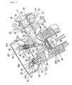
- an engine E is a water-cooled series 4-cylinder engine for a motorcycle, for example.
- a cylinder head 40 is fixed on the top face of a cylinder block 30, and a head cover 41 is mounted to the top face of the cylinder head 40.
- a cam chain case C is formed at a side portion of the engine E, #4 cylinder, #3 cylinder, #2 cylinder and #1 cylinder are arranged along the vehicle width direction from the side of the cam chain case C, and each of the cylinders is provided with two intake valves and two exhaust valves which will be described later.
- a throttle body 20 is connected to the cylinder head 40 substantially and horizontally.
- An intake duct 16 is connected on the upstream side of the throttle body 20, intake air passes through an intake passage 17, and is introduced to each cylinder via an intake port 18 in the cylinder head 40.
- a butterfly type throttle valve TH is provided in the intake passage 17 of the throttle body 20 in the state of being operable and closable between a fully opened position and a fully closed position.
- the throttle valve TH is of a so-called electronic throttle control system in which the throttle valve TH is opened and closed in conjunction with a motor 21 according to the grip opening (throttle operation variable) ⁇ g, i.e., the driver's intention toward acceleration or the like.
- a throttle valve opening sensor (throttle valve control mechanism) 22 for detecting the throttle valve opening is connected to the throttle valve TH so that the accurate turn angle of the throttle valve TH turned by the motor 21 can be detected.
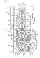
- a throttle body main body 200 is provided with four throttle valves TH, TH, TH, TH independent on the basis of each cylinder.
- the throttle body main body 200 is composed by interconnecting a third-fourth throttle body main body 200A corresponding to #4 cylinder and #3 cylinder, a second throttle body main body 200B corresponding to #2 cylinder, and a first throttle body main body 200C corresponding to #1 cylinder.
- #3 cylinder and #4 cylinder corresponding to the third-fourth throttle body main body 200A constitute a first cylinder group
- #2 cylinder corresponding to the second throttle body main body 200B constitutes a second cylinder group though it is a single cylinder
- #1 cylinder corresponding to the first throttle body main body 200C constitutes a third cylinder group though it is a single cylinder; thus, the engine is composed of the three cylinder groups.
- the throttle valve opening sensor 22 is coaxially mounted to the third-fourth throttle body main body 200A by small screws 24.
- a pulley 25 is mounted to an end portion, on the opposite side of the cam chain case C, of the third-fourth shaft 23.
- an injector 26 for injecting a fuel into each intake passage is inserted and fixed to an upper portion, or an upper wall, of the third-fourth throttle body main body 200A, inclinedly toward the cylinder head 40.
- the injector 26 is connected to a fuel supply pipe 27 (see FIG. 1 ).
- a third-fourth motor (throttle valve control mechanism) 21A is mounted to the third-fourth throttle body main body 200A on the opposite side of the injector 26 by a fastening means 29, with its drive shaft 28 set parallel to the third-fourth shaft 23.
- a pulley 31 is mounted to an end portion, on the opposite side of the cam chain case C, of the drive shaft 28 of the third-fourth motor 21A.
- a pulley 32 for opening and closing the throttle valve TH of the second throttle body main body 200B is mounted to an end portion on the opposite side of the cam chain case C.
- the throttle valve opening sensor 22 is mounted to a lower portion of the second throttle body main body 200B.
- a pulley 33 is mounted to an end portion, on the opposite side of the cam chain case C, of a sensor shaft 34 of the throttle valve opening sensor 22.
- a motor (throttle valve control mechanism) 21B is mounted to the front side of the throttle valve opening sensor 22 and on the opposite side of the injector 26 through a bracket (not shown), with its drive shaft set parallel to the shaft 35 of the throttle valve TH, and a pulley 36 is mounted to an end portion, on the opposite side of the cam chain case C, of a drive shaft of the motor 21B.
- a pulley groove 32M of the pulley 32 and a pulley groove of the pulley 36 of the motor 21B are connected by an endless wire 37, while a pulley groove 32 of the pulley 32 of the shaft 35 and a pulley groove of the pulley 33 of the throttle valve opening sensor 22 are connected by an endless wire 38.
- pulleys 32, 33, 36 are mounted to an end portion, on the opposite side of the cam chain case C, of the first throttle body main body 200C, and the throttle valve opening sensor 22 and the motor 21B in a font-rear relationship are mounted to a lower portion of the first throttle body main body 200C.
- the pulley 32 and the pulley 36 of the motor 21B are connected by an endless wire 37, while the pulley 32 and the pulley 33 of the throttle valve opening sensor 22 are connected by an endless wire 38.
- the cylinder head 40 is provided with a recessed portion 43 for defining a combustion chamber 42 together with the cylinder block 30 and a piston 39, and the recessed portion 43 is provided with intake valve ports 441, 442 and exhaust valve ports 451, 452.
- the first intake valve port 441 is opened and closed by a first intake valve 461, and the second intake valve port 442 is opened and closed by a second intake valve 462.
- the first exhaust valve port 451 is opened closed by a first exhaust valve 471, and the exhaust valve port 452 is opened and closed by a second exhaust valve 472.
- the first intake valve 461 is a restable intake valve
- the first exhaust valve 471 is a restable exhaust valve.
- the first and second intake valves 461, 462 have a configuration in which the base end of a valve stem 49 is integrally connected to a valve body portion 48 capable of closing the corresponding intake valve port 441, 442, and the first and second exhaust valves 471, 472 have a configuration in which the base end of a valve stem 51 is integrally connected to a valve body portion 50 capable of closing the corresponding exhaust valve port 451, 452.
- valve stems 49 ... of the first and second intake valves 461 and 462 are slidably fitted in guide cylinders 52 ... provided in the cylinder head 40.
- valve stems 51 ... of the first and second exhaust valves 471 and 472 are slidably fitted in guide cylinders 53 ⁇ provided in the cylinder head 40.
- a retainer 54 is fixed to a portion, projecting upward from the guide cylinder 52, of the valve stem 49 of the first intake valve 461, and the first intake valve 461 is biased in the direction of closing the first intake valve port 441 by a coil form valve spring 551 provided between the retainer 54 and the cylinder head 40.
- a retainer 54 is fixed to a portion, projecting upwards from the guide cylinder 52, of the valve stem 49 of the second intake valve 462, and the second intake valve 462 is biased in the direction of closing the second intake valve port 442 by a coil form valve spring 552 provided between the retainer 54 and the cylinder head 40.
- the first exhaust valve 471 is biased in the direction of closing the first exhaust valve port 451 by a coil form valve spring 571 provided between a retainer 56 fixed to the valve stem 51 of the first exhaust valve 471 and the cylinder head 40
- the second exhaust valve 472 is biased in the direction of closing the second exhaust valve port 452 by a coil form valve spring 572 provided between a retainer 56 fixed to the valve stem 51 of the second exhaust valve 472 and the cylinder head 40.
- the first and second intake valves 461 ⁇ , 462 ⁇ of the combustion chambers 42 ⁇ are driven by an intake-side valve operating device 58.
- the intake-side valve operating device 58 includes: a cam shaft 60 provided with first intake-side valve operating cams 591 ... corresponding respectively to the first intake valves 461 and second intake-side valve operating cams 592 ... corresponding respectively to the second intake valves 462 ... ; bottomed cylindrical valve lifters 611 ... slid by being driven by the first intake-side valve operating cams 591 ⁇ ; and bottomed cylindrical valve lifters 612 slid by being driven by the second intake-side valve operating cams 592 ⁇ .
- the cam shat 60 has an axis orthogonal to the extensions of the axes of the valve stems 49 ⁇ in the first and second intake valves 461 ⁇ , 462 ⁇ , and is rotatably supported between the cylinder head 40 and the head cover 41 joined to the cylinder head 40.
- the valve lifters 611 ⁇ are slidably fitted in the cylinder head 40 in the coaxial direction with the axes of the valve stems 49 ... in the first intake valves 461 ⁇ , and the closing end outside surfaces of the valve lifters 611 ... are in sliding contact with the first intake-side valve operating cams 591 ⁇ .
- valve lifter 612 ⁇ is slidably fitted in the cylinder head 40 in the coaxial direction with the axes of the valve stems 49 ⁇ in the second intake valves 462 ⁇ , and the closing end outside surfaces of the valve lifters 612 ⁇ are in sliding contact with the second intake-side valve operating cams 592 ⁇ .
- the stem ends of the valve stems 49 ⁇ in the second intake valve 462 are brought into contact with the closing end inside surface of the valve lifter 612 through a shim 62, and are normally opened and closed by the second intake-side valve operating cams 592 ⁇ during the operation of the engine E.
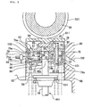
- a valve resting mechanism 63 which can change over between action and non-action of the pressing force in the valve-opening direction from the valve lifter 611 to the first intake valve 461 and which brings the first intake valve 461 into the rest state notwithstanding the sliding operation of the valve lifter 611 by bringing the pressing force into an inactive state in a specified operation range, for example, a low load range such as a low speed operation range of the engine E, is provided between the valve stems 49 ⁇ of the first intake valve 461 and the valve lifter 611.
- a specified operation range for example, a low load range such as a low speed operation range of the engine E
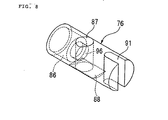
- the valve resting mechanism 63 includes a pin holder 74 slidably fitted in the vale lifter 611, a slide pin 76 slidably fitted in the pin holder 74 while forming an oil pressure chamber 75 between itself and the inside surface of the valve lifter 611, a return spring 77 provided between the slide pin 76 and the pin holder 74 while displaying a spring force for biasing the slide pin 76 in the direction of reducing the volume of the oil pressure chamber 75, and a stopper pin 78 provided between the pin holder 74 and the slide pin 76 while inhibiting the slide pin 76 from rotating about the axis thereof.
- a rest discrimination sensor 71 for detecting the position of the slide pin 76 is mounted on the side of the cylinder head 40.
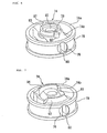
- the pin holder 74 has a ring portion 74a slidably fitted in the valve lifter 611 (see FIG. 5 ), and an annular groove 79 is provided in the outer circumference of the ring portion 74a.
- a bridging portion 74b connecting between inner circumference portions of the ring portion 74a is integrally formed along one diameter of the ring portion 74a, and the portions between the inner circumference of the ring portion 74a and both side surfaces of the bridging portion 74b are lightened, for contriving a reduction in weight.
- Such a pin holder 74 is formed by lost wax casting or forging of iron or an aluminum alloy, or formed from a synthetic resin, and a cementation treatment is applied to the outer circumferential surface of the pin holder 74, i.e., the outer circumferential surface of the ring portion 74a, which is made of a metal, and to the inner circumferential surface of the valve lifter 611.
- the bridging portion 74b is provided with a slide hole 80 having an axis in the longitudinal direction of the bridging portion 74b, i.e., in a direction orthogonal to the axis of the valve lifter 611.
- the slide hole 80 has a bottomed shape, with one end being opened to the annular groove 79 and the other end being closed.
- the bridging portion 74b is provided in its central lower portion with an insertion hole 81 communicated with the slide hole 80.
- the bridging portion 74b is provided in its central upper portion with an extension hole 82 communicated with the slide hole 80, coaxially with the insertion hole 81.
- the bridging portion 74b is integrally provided, in the periphery of the extension hole 82, with a hollow cylindrical containing tube portion 83 coaxially with the axis of the extension hole 82. Further, the bridging portion 74b is provided in its upper portion with a mount hole 90 communicated with the slide hole 80, in the range from a portion corresponding to the one end (open end) of the slide hole 80 to the extension hole 82. Similarly, as shown in FIG. 5 , the bridging portion 74b is provided in its lower portion with a mount hole 89 communicated with the slide hole 80, in the range from a portion corresponding to the one end of the slide hole 80 to the insertion hole 81. The mount hole 89 is formed coaxially with the mount hole 90, and the stopper pin 78 is mounted therein.
- a disk-like shim 84 is fitted in the containing tube portion 83 of the pin holder 74, and an end portion of the extension hole 82 is thereby closed.
- a stem end 49a of the valve stem 49 of the first intake valve 461 is inserted in the insertion hole 81 in the lower portion of the pin holder 74.
- the slide pin 76 is slidably fitted in the slide hole 80.
- the oil pressure chamber 75 communicated with the annular groove 79 is formed between one end of the slide pin 76 and the inside surface of the valve lifter 611, and the return spring 77 is contained in a spring chamber 86 formed between the other end of the slide pin 76 and the closed end of the slide hole 80.
- the pin holder 74 is made of a synthetic resin, its portion for sliding contact with the slide pin 76 may only be made of a metal.
- the slide pin 76 is provided with a containing hole 87 in an intermediate portion in the axial direction thereof.
- the containing hole 87 is coaxially communicated with the insertion hole 81 and the extension hole 82, and has such a diameter that the stem end 49a of the valve stem 49 can be contained therein. Further, an end portion, on the side of the insertion hole 81, of the containing hole 87 is opened to a flat abutment surface 88 formed on the outside surface of a lower portion of the slide pin 76 oppositely to the insertion hole 81.
- the abutment surface 88 is formed to be comparatively long along the axial direction of the slide pin 76, and the containing hole 87 is opened to a portion, on the side of the spring chamber 86, of the abutment surface 88.
- a slit 91 opened to the side of the oil pressure chamber 75 is provided on one end side of the slid pin 76.
- a magnetism generating member such as a magnet is embedded in the slid pin 76 so as to enhance the detection accuracy of a rest discriminating magnetic sensor 71 which will be described later.
- the slid pin 76 is provided with a communication hole 96 for communicating the spring chamber 86 with the containing hole 87, for preventing variations in the pressure inside the spring chamber 86 from occurring when the slid pin 76 is moved in the axial direction.
- the pin holder 74 is provided with a communication hole 97 for communicating the space between the pin holder 74 and the valve lifter 611 with the spring chamber 86, for preventing the pressure in the space from varying with temperature.
- a wall portion 79a of the annular groove 79 forming the spring chamber 86 is provided with an opening 79b. The diameter of the opening 79b is set smaller than the diameter of the return spring 77.
- a coil spring 92 for biasing the pin holder 74 in the direction of abutting the shim 84 mounted to the pin holder 74 against the projected portion 85 of the valve lifter 611 is provided between the pin holder 74 and the cylinder head 40.
- the coil spring 92 is so mounted as to surround the valve stem 49 at such a position as to obviate the contact of its outer circumference with the inside surface of the valve lifter 611, and the bridging portion 74b of the pin holder 74 is integrally provided with a pair of projections 93, 94 for positioning an end portion of the coil spring 92 in a direction orthogonal to the axis of the valve stem 49.
- Both the projections 93, 94 are projectingly provided integrally on the pin holder 74 with a projection amount not more than the wire diameter of the coil spring 92, and is formed in a circular arc shape, with the axis of the valve stem 49 as a center of the circle.
- one 93 of the projections 93, 94 is provided with a step portion 95 which abuts on an end portion, on the side of the first intake valve 461, of the stopper pin 78 to thereby inhibit the stopper pin 78 from moving to the side of the first intake valve 461.
- the cylinder head 40 is provided with a support hole 98 for fitting the valve lifter 611 therein so as to slidably support the valve lifter 611, and the support hole 98 is provided in its inside surface with an annular recessed portion 99 for surrounding the valve lifter 611.
- the annular recessed portion 99 is connected to a working oil pressure supply passage 103 formed in the cylinder head 40, and is supplied with a working oil.
- the valve lifter 611 is provided with a release hole 101 and a communication hole 100 for communicating the annular recessed portion 99 with the annular groove 79 in the pin holder 74.
- the communication hole 100 is provided at such a position as to communicate the annular recessed portion 99 with the annular groove 79 notwithstanding the sliding of the valve lifter 611 in the support hole 98.
- the release hole 101 is provided in the valve lifter 611 at such a position that the annular recessed portion 99 is communicated with the inside of the valve lifter 611 on the lower side of the pin holder 74 when the valve lifter 611 is moved to an uppermost position as shown in FIG. 5 and that the communication with the annular recessed portion 99 is interrupted as the valve lifter 611 is moved downwards from the uppermost position as shown in FIG. 5 , and the working oil is jetted through the release hole 101 into the inside of the valve lifter 611 as a lubricating oil.
- the working oil supplied from the working oil pressure supply passage 103 into the annular groove 79 of the pin holder 74 through the communication hole 100 and the release hole 101 is supplied into the oil pressure chamber 75 via one end of the slide hole 80.
- the slide pin 76 is slid in the axial direction in such a manner that an oil pressure force acting on one end side of the slide pin 76 due to the oil pressure inside the oil pressure chamber 75 and a spring force acting on the other end side of the slide pin 76 due to the return spring 77 balance each other.
- the stem end 49a of the valve stem 49 inserted in the insertion hole 81 is moved to the right side in FIG.
- the rotation of the slide pin 76 about its axis is inhibited by the stopper pin 78.
- the stopper pin 78 pierces through the slit 91 of the slide pin 76.
- the stopper pin 78 is mounted to the pin holder 74 by piercing through the slide pin 76 while permitting the slide pin 76 to move in the axial direction, so that the abutment of the stopper pin 78 on an inner end closed portion of the slit 91 restricts the end of movement of the slide pin 76 to the side of the oil pressure chamber 75.
- the rest discriminating magnetic sensor 71 is mounted to the annular recessed portion 99 of the cylinder head 40 while fronting on the communication hole in the valve lifter 611 and on the opening 79b in the pin holder 76.
- the rest discriminating magnetic sensor 71 is a sensor which is for detecting the distance ds from the rest discriminating magnetic sensor 71 through the communication hole 100 and the opening 79b to a wall portion 76a of the slide pin 76, includes a magnet and a coil, and detects the distance ds by detecting a magnetic flux variation generated when the slide pin 76 made of a metal is moved.
- a cable 71a for outputting the detection results is connected to the rest discriminating magnetic sensor 71.
- the cable 71a is passed through an insertion hole formed in the cylinder head 40, and is connected to an ECU (cylinder number control unit) 70 (see FIG. 9 ) which will be described later.
- a rest discriminating sensor is not limited to the magnetic sensor; there may be used a sensor for detecting the distance ds by use of light, a sensor for detecting the distance ds by detecting a variation in electrostatic capacity, a sensor for detecting the distance ds by use of ultrasound, and the like.
- the first and second exhaust valves 471 ⁇ , 472 ⁇ of the combustion chambers 42 ⁇ are driven by an exhaust-side valve operating device 68.
- the exhaust-side valve operating device 68 has a camshaft 65 provided with a first exhaust-side valve operating cams 641 ⁇ corresponding respectively to the first exhaust valves 471 ⁇ and with second exhaust-side valve operating cams 642 ⁇ corresponding respectively to the second exhaust valves 472 ⁇ , and has bottomed hollow cylindrical valve lifters 661 ⁇ slid while being driven by the first exhaust-side valve operating cams 641 ⁇ and bottomed hollow cylindrical valve lifters 662 ⁇ slid while being driven by the second exhaust-side valve operating cams 642 ⁇ .
- the camshaft 65 has an axis orthogonal to the extensions of the axes of the valve stems 51 ... of the first and second exhaust valves 471 ⁇ , 472 ⁇ , and is rotatably supported between the cylinder head 40 and the head cover 41 joined to the cylinder head 40, like the camshaft 60 of the intake-side valve operating device 58.
- the valve lifters 661 ⁇ are slidably fitted in the cylinder head 40 coaxially with the axes of the valve stems 51 ... of the first exhaust valves 471 ..., and the outside surfaces of the closed ends of the valve lifters 661 ⁇ are in sliding contact with the first exhaust-side valve operating cams 641 ⁇ .
- valve lifters 662 ⁇ are slidably fitted in the cylinder head 40 coaxially with the axes of the valve stems 51 ⁇ of the second exhaust valves 472 ⁇ , and the outside surfaces of the closed ends of the valve lifters 662 ⁇ are in sliding contact with the second exhaust-side valve operating cams 642 ⁇ .
- valve stem 51 ⁇ of the second exhaust valve 472 abuts on the inside surface of the closed end of the valve lifter 662 through the shim 67, and are normally opened and closed by the second exhaust-side valve operating cam 642 ... during the operation of the engine E.
- a valve resting mechanism 69 which can change over the action and non-action of the pressing force exerted from the valve lifter 661 on the first exhaust valve 471 in the valve-opening direction and which brings the first exhaust valve 471 into a resting state irrespectively of the sliding of the valve lifter 661 by putting the pressing force into an inactive state in a specified operation range of the engine E, for example, in a low load range such as a low speed operation range, is provided between the stem ends 51a of the valve stem 51 ⁇ of the first exhaust valve 471 and the valve lifter 661.
- the valve resting mechanism 69 of the exhaust-side valve operating device 68 is configured in the same manner as the valve resting mechanism 63 (see FIG. 5 ) in the intake-side valve operating device 58.
- valve resting mechanism 63 and the valve resting mechanism 69 configured in the same manner as in #4 cylinder are provided for the second exhaust valve 472 (corresponding to a second exhaust valve port 452) and the second intake valve 462 (corresponding to a second intake valve port 442), in the manner contrary to that in #4 cylinder. Further, in #1 cylinder and #2 cylinder, the valve resting mechanism 63 and the valve resting mechanism 69 are provided for all the intake valves 461, 462 and the exhaust valves 471, 472.
- valve resting mechanisms 63, 69 are provided for all the engine valves, these valve resting mechanisms 63, 69 function as a cylinder resting mechanism, and a cylinder rest where all the engine valves are in rest (the cylinders are restable cylinders) can be performed.
- a valve rest where one engine valve each on the intake side and the exhaust side is in rest (the cylinders are normally operative cylinders) can be performed.
- a side wall on the #4 cylinder side of the cylinder head 40 is provided with a cam chain case C, and a cam chain (not shown) for driving the camshafts 60, 65 of the intake-side and exhaust-side valve operating devices 58, 68 are contained in the cam chain case C.
- a side wall of the cylinder head 40 on the opposite side of the cam chain case C is provided with connection ports PA, PB, PC of oil pressure control valves 113A, 113B, 113C for controlling the supply of the working oil to the valve resting mechanisms 63 ⁇ , 69 ⁇ (see FIGS. 2 and 3 ) of the intake-side and exhaust-side valve operating devices 58, 68.
- connection port PA is connected to a working oil supply passage 103A which is extended in the cylinder head 40 between a central portion in the front-rear direction of the cylinder head 40 to each intake valve port along the longitudinal direction to the layout position of the second intake valve port 442 of #2 cylinder and which is branched toward the second intake valve port 442 of #2 cylinder and the second exhaust valve port 452 of #2 cylinder.
- connection port PB is connected to a working oil supply passage 103B which is extended in the cylinder head 40 between a central portion in the front-rear direction of the cylinder head 40 to each exhaust valve port along the longitudinal direction to the layout position of the first exhaust valve port 451 of #1 cylinder and which is branched toward the first exhaust valve port 451 of #1 cylinder and the first intake valve port 441 of #1 cylinder.
- connection port PC is connected to a working oil supply passage 103C which is extended in the other side wall of the cylinder head 40 along the longitudinal direction to the layout position of the first exhaust valve port 451 of #4 cylinder and which is branched toward the first exhaust valve port 451 of #4 cylinder, the second exhaust valve port 452 of #3 cylinder, the first exhaust valve port 451 of #2 cylinder and the second exhaust valve port 452 of #1 cylinder.
- a working oil supply passage 103C' is formed in the rear side wall of the cylinder head 40 along the longitudinal direction of the cylinder head 40 to the layout position of the first intake valve port 441 of #4 cylinder, and the working oil supply passage 103C and the working oil supply passage 103C' are connected to each other through a crossing passage 103X.
- the working oil supply passage 103C' is branched to be connected to the first intake valve port 441 of #4 cylinder, the second intake valve port 442 of #3 cylinder, the first intake valve port 441 of #2 cylinder and the second intake valve port 442 of #1 cylinder.
- #1 cylinder and #2 cylinder among #1 cylinder, #2 cylinder and #3 cylinder i.e., the cylinders located on the opposite side of the cam chain case C, all the engine valves consisting of the first intake valve 461, the second intake valve 462, the first exhaust valve 471 and the second exhaust valve 472 are configured to be restable.
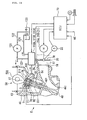
- the oil pressure control valves 113A, 113B, 113C are supplied with the working oil which is reserved in an oil pan 120.
- a main oil pressure passage 122 fitted with a pump 121 is connected to the oil pan 120, and, on the discharge side of the pump 121, a branch passage 123 connected to the oil pressure control valves 113A, 113B, 113C is branched from the main oil pressure passage 122.
- the drain ports D (see FIG. 1 ) of the oil pressure control valves 113A, 113B, 113C are connected to a drain passage 124 so that the working oil can be recovered into the oil pan 120.
- the control of the oil pressure control valves 113A, 113B, 113C is conducted by the ECU 70, which is an electronic control unit, based on the grip opening ⁇ g detected by a grip opening sensor G, the engine speed Ne, the rest discriminating magnetic sensor 71 and the like.
- the ECU 70 controls the throttle valve TH by outputting a turning command signal to each of the motors 21A, 21B while detecting the throttle valve opening by a throttle valve opening sensor 22 so as to set optimum the throttle valve opening based on the value detected by the grip opening sensor G and the like.
- fuel injection amount at the injector 26 is regulated based on a control signal from the ECU 70.
- the ECU 70 has means for changing over the oil pressure control valves 113A, 113B, 113C, means for controlling the throttle valve opening, and a means for controlling the fuel injection amount.
- the valve rest and the cylinder rest conducted under the control by the ECU 70 will be described, the description being centered on the operations of the intake valves 461, 462 and the exhaust valves 471, 472 provided with the valve resting mechanisms 63, 69.
- the ECU 70 drives the throttle valve TH by outputting the turning command signal to each of the motors 21A, 21B while detecting the throttle valve opening by the throttle valve opening sensor 22, based on the detection signals fed from the grip opening sensor G and the like.
- the fuel injection amount at the injector 26 is regulated based on the control signal from the ECU 70.
- the oil pressure chamber 75 of the valve resting mechanism 63 is supplied with the working oil via the working oil supply passage 103, whereby the return spring 77 is compressed, and the slide pin 76 is located on a comparatively left side in FIG. 9 .
- the valve resting mechanism 69 on the exhaust side as shown in FIG. 2 is also configured so that the oil pressure of the working oil acts on the slide pin 76.
- the processing by the ECU 70 in the case where predetermined conditions are fulfilled and the valve rest and cylinder rest are conducted will be described based on a flow chart shown in FIG. 10 .
- the ECU 70 detects the grip opening ⁇ g (step S1), and the passage of current to the injector 26 is stopped, thereby stopping the fuel supply (F1) (step S2). Thereafter, the exhaust valves 471, 472 and the intake valves 461, 462 are rested (step S3).
- the resting of the exhaust valves 471, 472 and the intake valves 461, 462 is carried out as follows. After the completion of the exhaust stroke is confirmed by a crank angle sensor (not shown) or the like, a control signal is outputted to each of the oil pressure control valves 113A, 113B, 113C, to discharge the working oil from the oil pressure chamber 75 (see FIG. 5 ), and the exhaust valves 471, 472 are rested. The resting of the exhaust valves 471, 472 is confirmed by use of the rest discriminating magnetic sensor 71.
- the ECU 70 determines that the exhaust valves 471, 472 corresponding to the rest discriminating magnetic sensor 71 has come to a rest.
- a control signal is outputted to each of the oil pressure control valves 113A,. 113B, 113C, to stop the intake valves 461, 462.
- the resting of the intake valves 461, 462 is also conducted based on the distance ds detected by the rest discriminating magnetic sensor 71 provided in the vicinity of the stem end 49a of each of the intake valves 461, 462, in the same manner as above.
- the throttle valve TH is put into a closed state by driving the motors 21A, 21B (step S4), and the supply of electric power to the spark plug is interrupted (step S5).
- the cutoff of ignition is carried out several cycles (in this embodiment, 10 cycles), and thereafter the ignition is reset.
- the working oil is discharged via the drain passage 124 as shown in FIG. 11 , the slide pin 76 is moved by the force of the return spring 77 so as to reduce the oil pressure chamber 75, and the containing hole 87 is matched to the insertion hole 81 in the pin holder 74.
- the stem end 49a (see FIG. 5 ) of the valve stem 49 is only contained into the insertion hole 81 and the containing hole 87, and no pressing force is exerted on the first intake valve 461, so that the first intake valve port 441 is kept closed.
- the working oil is similarly discharged also from the valve resting mechanism 69 on the exhaust side as shown in FIG. 3 , the containing hole 87 is matched to the insertion hole 81 in the pin holder 74, and no pressing force is exerted on the first exhaust valve 471, so that the first exhaust valve port 451 is kept closed.
- the ECU 70 detects the grip opening ⁇ g (step S11), and brings the throttle valve TH into an open state by driving the motors 21A, 21B while detecting the throttle valve opening by the throttle valve opening sensor 22, based on the grip opening ⁇ g (step S12). Then, the intake valves 461, 462 and the exhaust valves 471, 472 are operated (step S13). The operations of the exhaust valves 471, 472 and the intake valves 461, 462 are conducted as follows.
- a control signal is outputted to each of the oil pressure control valves 113A, 113B, 113C, whereby an oil pressure is exerted on the slide pin 76 to move the slide pin 76, to operate the first exhaust valve 471.
- the operations of the exhaust valves 471, 472 are confirmed by use of the rest discriminating magnetic sensor 71.
- the ECU 70 determines that the exhaust valve 471, 472 corresponding to the rest discriminating magnetic sensor 71 has changed over to an operative state.
- a control signal is outputted from the ECU 70 to each of the oil pressure control valves 113A, 113B, 113C (see FIG. 1 ), whereby the intake valves 461, 462 are operated.
- the operations of the intake valves 461, 462 are confirmed based on the distance ds detected by the rest discriminating magnetic sensor 71, in the same manner as above.
- the injector 16 is operated, to start the fuel supply (step S14). Incidentally, in this instance, the cutoff of ignition has been reset, so that the engine is driven by starting the fuel supply.
- the engine valves (the exhaust valves 471, 472 and the intake valves 461, 462) are operated according to the grip opening ⁇ g and how the throttle valve TH is opened to increase the engine output will be described, based on FIGS. 14 to 16 .
- the hatched valves are the engine valves in the resting state.
- the intake valves 461, 462 and the exhaust valves 471, 472 which are the engine valves are all rested (all valve rest), the cylinder rest results.
- first intake valve 461 and the first exhaust valve 472 are disposed on a diagonal line
- second intake valve 462 and the second exhaust valve 472 are disposed on a diagonal line
- the adjacent exhaust valves 471, 472 of the two adjacent cylinders are configured as operative cylinders
- a secondary air introduction valve (exhaust device) AI is provided between the exhaust valves 471, 472 (exclusive of the portion between #2 cylinder and #3 cylinder).
- the cylinders to be operated and the throttle valve opening in each cylinder group are determined uniquely, on the basis of the grip opening ⁇ g best representing the driver's intention to accelerate. Specifically, the number of the cylinder groups to be operated is increased with an increase in at least the grip opening ⁇ g. In addition, whether the cylinder is to be rested or operated is determined based on whether the engine speed Ne is higher or lower than a threshold value. These are controlled by the ECU 70.
- the cylinder rest (all valve rest) is conducted in #1 cylinder and #2 cylinder, the valve rest is conducted in #3 cylinder and #4 cylinder, and, in this condition, the throttle valve opening is gradually increased with an increase in the grip opening ⁇ g.
- the throttle valve TH for #3 cylinder and #4 cylinder is gradually opened (2-cylinder 2-valve operation shown in FIG. 13 ).
- the average of an increase ratio (dTH/d ⁇ g) of the throttle valve opening to the grip opening in #3 cylinder and #4 cylinder is set higher than the average of the increase ratio of the throttle valve opening to the grip opening in #2 cylinder.
- valve rest is conducted in all cylinders from #1 cylinder to #4 cylinder, and, in this condition, the throttle valve TH of #1 cylinder is started to open, in addition to #3 cylinder, #4 cylinder, and #2 cylinder in which the throttle valve thereafter increases continuedly.
- the throttle valve TH in #1 cylinder, in addition to #3 cylinder and #4 cylinder is gradually opened (4-cylinder 2-valve operation shown in FIG. 13 ).
- the throttle valve openings in #3 cylinder and #4 cylinder, in #2 cylinder, and in #1 cylinder are different, except for the fully opened time and the fully closed time of the throttle valve TH, and the throttle valve TH in the next cylinder group is opened before the throttle valve opening in the former cylinder group reaches the fully opened state. Therefore, as compared to the case where the throttle valves in all cylinder groups are simultaneously opened to thereby increase the output, the engine E can be operated with high combustion efficiency, which can contribute to improvement of fuel consumption.
- the throttle valve in the next cylinder group is opened before the throttle valve opening in the former cylinder group reaches the fully opened state, it is possible to eliminate the step in output, and to realize a smooth operation.
- the average of the increase ratio (dTH/d ⁇ g) of the throttle valve opening to the grip opening in #3 cylinder and #4 cylinder whose throttle valves are opened first is set higher than the average of the increase ratio of the throttle valve opening to the grip opening in #2 cylinder whose throttle opening is next started to open. Further, the average of the increase ratio of the throttle valve opening to the grip opening in #2 cylinder is set higher than that in #1 cylinder whose throttle valve is next started to open. In other words, the increase ratio in a cylinder whose throttle valve is opened first at the time of starting the grip operation is set to be high, and the increase ratios in the cylinders whose throttle valves are thereafter opened sequentially are set to be gradually lowered. Referring to FIG. 13 , the inclinations of the three lines are so set that the inclination is greater as the line is located on the more left side.
- the increase ratio is high in a low load range, by bringing the throttle valve opening to the fully opened state earlier, it is possible to operate in the range with a higher load factor, and to reduce the pumping loss, so that an improvement in fuel consumption can be contrived. Since specified valves are rested and 2-valve operation is conducted at a low load time, it is possible, at the low load time, to limit the intake air amount and bring the throttle valve to the fully opened state earlier, and thereby to generate an intake swirl. As a result, the engine can be operated in a high load factor range which is advantageous in view of improvement of fuel consumption. In short, a swirl can be easily generated in the cylinder by the first intake valve 461 and the first exhaust valve 471 which are disposed on a diagonal line or by the second intake valve 462 and the second exhaust valve 472 which are disposed on a diagonal line.
- the number of cylinders can be varied according to not only the grip operation but also the engine speed Ne, it is possible to appropriately enhance the load factor of each cylinder, and to achieve compatibility between engine output and fuel consumption.
- the number of operative cylinders is four, so that an appropriate engine brake can be secured.
- cylinder rest can be realized by resting the intake valves 461, 462 and the exhaust valves 471, 472, the pumping loss can be reduced, and an improvement in fuel consumption can be contrived.
- the output can be made appropriate.
- the motors 21A, 21B, the throttle valve opening sensor 22 and the like which are driven and controlled by the ECU 70 are provided for each of the cylinder groups, the output variations at the time of changing over the valves can be suppressed.
- the layout position of the secondary air introduction valve AI can be made compact. Besides, since it is possible to operate in a range where the load factor of each cylinder is high by increasing the number of cylinders from two cylinders by one cylinder at a time, fuel consumption can be improved also from this point of view.
- the present invention is not limited to the above-described embodiment; while the invention has been described taking a motorcycle as an example, it can be applied also to four-wheeled vehicles. In that case, acceleration pedal opening can be used in place of grip opening.
- the present invention is not limited to 4-cylinder engine, and the combination of cylinders and the number of cylinder groups can be set freely; for example, the invention is applicable to a 6-cylinder engine, where three of the cylinders constitute a cylinder group, two of the cylinders constitute another cylinder group, and the remaining one of the cylinders singly constitutes a cylinder group.
- valve resting mechanism is a mere example, and a valve resting mechanism of the type in which valve rest is achieved by use of a rocker arm can be adopted. Besides, all cylinders may be put into all valve rest. Further, while the description has been made of the case where 4-cylinder operation is established when the engine speed Ne in 2-cylinder operation has exceeded the threshold value ⁇ , various modes can be adopted; for example, transition from 2-cylinder operation to 3-cylinder operation and further to 4-cylinder operation according to the engine speed Ne may be adopted.
Landscapes
- Engineering & Computer Science (AREA)
- Mechanical Engineering (AREA)
- General Engineering & Computer Science (AREA)
- Chemical & Material Sciences (AREA)
- Combustion & Propulsion (AREA)
- Output Control And Ontrol Of Special Type Engine (AREA)
- Valve Device For Special Equipments (AREA)
- Control Of Throttle Valves Provided In The Intake System Or In The Exhaust System (AREA)
- Combined Controls Of Internal Combustion Engines (AREA)
Claims (4)
- Brennkraftmaschine (E) mit Zylinderabschaltung mit mehreren Zylindern (#1 - #4), die normalerweise arbeitende Zylinder (#3, #4) sind, wobei einige von mehreren Zylindern (#1, #2) abgeschaltet sind, worin alle Zylinder (#1 - #4) in mehrere Zylindergruppen unterteilt sind, jeder Zylinder (#1 - #4) mit einer individuellen Drosselklappe (TH) bereitgestellt ist, die Drosselklappen (TH) durch die Motoren (21A, 21B) angetrieben werden, wobei mehrere der Drosselklappen (TH), die den normalerweise arbeitenden Zylindern (#3, #4) entsprechen, durch einen Motor (21 A) angetrieben werden, eine Zylinderzahlsteuereinheit (70) zum Erhöhen der Anzahl der arbeitenden Zylindergruppen gemäß wenigstens einer Drosselklappenbetriebsvariable (θg) bereitgestellt ist und ein Drosselklappensteuermechanismus (21A, 21B), um die Drosselklappe(n) (TH) der abgeschalteten Zylinder (#1, #2) basierend auf jeder Zylindergruppe in einen vollständig geschlossenen Zustand zu bringen,
dadurch gekennzeichnet, dass
die Zylinderzahlsteuereinheit (70) gestaltet ist, die Anzahl der arbeitenden Zylindergruppen zu erhöhen, wenn die Motordrehzahl nicht weniger als ein vorherbestimmter Wert (α) in dem Zustand beträgt, in dem sich wenigstens einige der Zylindergruppen in dem abgeschalteten Zustand befinden. - Brennkraftmaschine (E) mit Zylinderabschaltung nach Anspruch 1,
dadurch gekennzeichnet, dass
der Zylinder vier oder mehr Ventile (461, 462) aufweist, ein Ventilabschaltmechanismus zum Herstellen eines Zylinderabschaltzustands durch Herbeiführen eines Abschaltzustands aller Ventile bereitgestellt ist, in dem alle Ventile (461, 462) des Zylinders abgeschaltet sind, und eine teilweise Ventilbetätigung ausgeführt werden kann, indem einige der Ventile (461, 462) jedes Zylinder entsprechend einer Motordrehzahl in einen Abschaltzustand gebracht werden. - Brennkraftmaschine (E) mit Zylinderabschaltung nach einem der vorhergehenden Ansprüche,
dadurch gekennzeichnet, dass
zum Zeitpunkt der teilweisen Ventilabschaltung benachbarte Auslassventile (471, 472) in zwei benachbarten Zylindern als arbeitende Ventile ausgewählt werden und ein sekundäres Lufteinlassventil (AI) zwischen den benachbarten Auslassventilen (471, 472) bereitgestellt ist. - Brennkraftmaschine (E) mit Zylinderabschaltung nach einem der vorhergehenden Ansprüche,
dadurch gekennzeichnet, dass
vier Zylinder (#1 - #4) bereitgestellt sind und die Anzahl der arbeitenden Zylinder in der Weise zwei Zylinder, drei Zylinder und vier Zylinder einhergehend mit einer Zunahme der Drosselklappenbetätigungsmenge erhöht wird.
Applications Claiming Priority (1)
| Application Number | Priority Date | Filing Date | Title |
|---|---|---|---|
| JP2004259615A JP4327050B2 (ja) | 2004-09-07 | 2004-09-07 | 気筒休止内燃機関 |
Publications (2)
| Publication Number | Publication Date |
|---|---|
| EP1632663A1 EP1632663A1 (de) | 2006-03-08 |
| EP1632663B1 true EP1632663B1 (de) | 2008-12-17 |
Family
ID=35149635
Family Applications (1)
| Application Number | Title | Priority Date | Filing Date |
|---|---|---|---|
| EP05017244A Expired - Fee Related EP1632663B1 (de) | 2004-09-07 | 2005-08-08 | Brennkraftmaschine mit Zylinderabschaltung |
Country Status (4)
| Country | Link |
|---|---|
| US (1) | US7188600B1 (de) |
| EP (1) | EP1632663B1 (de) |
| JP (1) | JP4327050B2 (de) |
| DE (1) | DE602005011719D1 (de) |
Families Citing this family (12)
| Publication number | Priority date | Publication date | Assignee | Title |
|---|---|---|---|---|
| US7488273B2 (en) | 2006-06-30 | 2009-02-10 | Harley-Davidson Motor Company Group, Inc. | Cylinder deactivation for a motorcycle engine |
| JP4601591B2 (ja) * | 2006-09-08 | 2010-12-22 | 本田技研工業株式会社 | バルブ休止機構を備える内燃機関の動弁装置 |
| JP2008255803A (ja) | 2007-03-30 | 2008-10-23 | Honda Motor Co Ltd | 気筒休止機能付き多気筒エンジン |
| JP4801819B2 (ja) | 2007-03-30 | 2011-10-26 | 本田技研工業株式会社 | 自動二輪車用多気筒エンジン |
| JP4810490B2 (ja) | 2007-03-30 | 2011-11-09 | 本田技研工業株式会社 | 車両用v型エンジン |
| JP4922044B2 (ja) | 2007-03-30 | 2012-04-25 | 本田技研工業株式会社 | 自動二輪車用v型4気筒エンジン |
| JP4846679B2 (ja) | 2007-08-31 | 2011-12-28 | 本田技研工業株式会社 | 車両用v型エンジン |
| DE102009054184A1 (de) * | 2009-11-23 | 2011-05-26 | Mahle International Gmbh | Klappenvorrichtung und Sauganlage |
| US20120118265A1 (en) * | 2010-11-17 | 2012-05-17 | Gm Global Technology Operations, Inc. | Engine assembly including independent throttle control for deactivated cylinders |
| US10138819B2 (en) * | 2014-12-09 | 2018-11-27 | Kawasaki Jukogyo Kabushiki Kaisha | Vehicle, straddle-type vehicle, and method of driving throttle valve |
| US10018125B2 (en) * | 2015-09-04 | 2018-07-10 | Cher Sha | Digital internal combustion engine and method of control |
| US11143117B2 (en) | 2019-12-04 | 2021-10-12 | Mikuni Corporation | Throttle device |
Family Cites Families (16)
| Publication number | Priority date | Publication date | Assignee | Title |
|---|---|---|---|---|
| JPS5484135A (en) * | 1977-12-19 | 1979-07-04 | Toyota Motor Corp | Divided driving control type internal combustion engine |
| JPS5835244A (ja) * | 1981-08-27 | 1983-03-01 | Yamaha Motor Co Ltd | 作動気筒選択式エンジン |
| US4587936A (en) * | 1981-09-10 | 1986-05-13 | Honda Giken Kogyo Kabushiki Kaisha | Control apparatus for intake and exhaust valves of an internal combustion engine |
| IT1149700B (it) * | 1982-02-26 | 1986-12-03 | Alfa Romeo Auto Spa | Motore pluricilindrico a c.i.di tipo modulare |
| SU1118781A1 (ru) * | 1982-12-09 | 1984-10-15 | Киевский Ордена Ленина Политехнический Институт Им.50-Летия Великой Октябрьской Социалистической Революции | Система питани дл многоцилиндрового двигател внутреннего сгорани |
| JPH0617655B2 (ja) * | 1984-04-25 | 1994-03-09 | マツダ株式会社 | 気筒数制御エンジンのスロツトル弁制御装置 |
| JPH06101437A (ja) * | 1992-09-18 | 1994-04-12 | Aisin Seiki Co Ltd | エンジンの動弁装置 |
| JPH07150982A (ja) * | 1993-11-30 | 1995-06-13 | Sanshin Ind Co Ltd | 多気筒エンジンの出力制御装置 |
| US5758612A (en) * | 1994-08-31 | 1998-06-02 | Yamaha Hatsudoki Kabushiki Kaisha | Valve actuating structure for multi-valve engine |
| JP3175491B2 (ja) * | 1994-09-01 | 2001-06-11 | トヨタ自動車株式会社 | 可変気筒エンジンの制御装置 |
| JP3358887B2 (ja) | 1994-09-20 | 2002-12-24 | 本田技研工業株式会社 | 気筒数制御内燃機関 |
| JP2940413B2 (ja) | 1994-10-05 | 1999-08-25 | 三菱自動車工業株式会社 | 可変気筒機構付き内燃機関 |
| JPH08319811A (ja) | 1995-05-25 | 1996-12-03 | Shin Caterpillar Mitsubishi Ltd | カートリッジ型フィルタ |
| DE10148347A1 (de) * | 2001-09-29 | 2003-04-10 | Bosch Gmbh Robert | Momentenneutrale Zylinderabschaltung durch Deaktivierung von Gaswechselventilen |
| JP4202166B2 (ja) * | 2003-03-26 | 2008-12-24 | 本田技研工業株式会社 | 多気筒エンジン |
| JP4463488B2 (ja) * | 2003-03-27 | 2010-05-19 | 本田技研工業株式会社 | スロットルボディ |
-
2004
- 2004-09-07 JP JP2004259615A patent/JP4327050B2/ja not_active Expired - Fee Related
-
2005
- 2005-08-08 DE DE602005011719T patent/DE602005011719D1/de active Active
- 2005-08-08 EP EP05017244A patent/EP1632663B1/de not_active Expired - Fee Related
- 2005-09-07 US US11/220,857 patent/US7188600B1/en active Active
Also Published As
| Publication number | Publication date |
|---|---|
| JP4327050B2 (ja) | 2009-09-09 |
| US20070039586A1 (en) | 2007-02-22 |
| EP1632663A1 (de) | 2006-03-08 |
| DE602005011719D1 (de) | 2009-01-29 |
| US7188600B1 (en) | 2007-03-13 |
| JP2006077587A (ja) | 2006-03-23 |
Similar Documents
| Publication | Publication Date | Title |
|---|---|---|
| EP1632663B1 (de) | Brennkraftmaschine mit Zylinderabschaltung | |
| EP1632664B1 (de) | Brennkraftmaschine mit Zylinderabschaltung | |
| CA2603483C (en) | Multicylinder internal combustion engine | |
| US6425357B2 (en) | Variable valve drive mechanism and intake air amount control apparatus of internal combustion engine | |
| US4892067A (en) | Valve control system for engines | |
| CA1331118C (en) | Failsafe method in connection with valve timing-changeover control for internal combustion engines | |
| JP5112473B2 (ja) | 気筒休止内燃機関 | |
| EP1462644B1 (de) | Drosselklappenstutzen | |
| EP0543679A1 (de) | Zündanlage für Brennkraftmaschine mit mindestens zwei Zündkerzen pro Zylinder | |
| JP4626994B2 (ja) | 内燃機関 | |
| JP5249887B2 (ja) | エンジンの制御装置 | |
| EP0818611B1 (de) | Variable Ventilsteuervorrichtung für Verbrennungsmotor | |
| JP2005090463A (ja) | 気筒休止制御エンジン | |
| JP2005105869A (ja) | 可変気筒内燃機関 | |
| JPH0364606A (ja) | 多弁式4サイクルエンジン | |
| JP3075126B2 (ja) | 内燃機関のバルブタイミング制御装置 | |
| JP3346248B2 (ja) | 可変バルブタイミング機構付き内燃機関の可変気筒制御装置 | |
| JPH10252428A (ja) | 内燃機関のバルブ特性制御装置 | |
| JPH09170440A (ja) | 内燃機関の出力制御装置 | |
| JP2023150515A (ja) | 内燃機関の制御装置 | |
| JPH1136907A (ja) | 内燃機関のバルブタイミング制御装置 | |
| JP4186387B2 (ja) | 内燃機関の電磁駆動式動弁機構 | |
| JP2663762B2 (ja) | エンジンの可変動弁装置 | |
| JPH0972207A (ja) | 内燃機関のバルブタイミング制御装置 |
Legal Events
| Date | Code | Title | Description |
|---|---|---|---|
| PUAI | Public reference made under article 153(3) epc to a published international application that has entered the european phase |
Free format text: ORIGINAL CODE: 0009012 |
|
| 17P | Request for examination filed |
Effective date: 20050808 |
|
| AK | Designated contracting states |
Kind code of ref document: A1 Designated state(s): AT BE BG CH CY CZ DE DK EE ES FI FR GB GR HU IE IS IT LI LT LU LV MC NL PL PT RO SE SI SK TR |
|
| AX | Request for extension of the european patent |
Extension state: AL BA HR MK YU |
|
| AKX | Designation fees paid |
Designated state(s): DE FR IT |
|
| 17Q | First examination report despatched |
Effective date: 20071106 |
|
| GRAP | Despatch of communication of intention to grant a patent |
Free format text: ORIGINAL CODE: EPIDOSNIGR1 |
|
| GRAS | Grant fee paid |
Free format text: ORIGINAL CODE: EPIDOSNIGR3 |
|
| GRAA | (expected) grant |
Free format text: ORIGINAL CODE: 0009210 |
|
| AK | Designated contracting states |
Kind code of ref document: B1 Designated state(s): DE FR IT |
|
| REF | Corresponds to: |
Ref document number: 602005011719 Country of ref document: DE Date of ref document: 20090129 Kind code of ref document: P |
|
| PLBE | No opposition filed within time limit |
Free format text: ORIGINAL CODE: 0009261 |
|
| STAA | Information on the status of an ep patent application or granted ep patent |
Free format text: STATUS: NO OPPOSITION FILED WITHIN TIME LIMIT |
|
| 26N | No opposition filed |
Effective date: 20090918 |
|
| REG | Reference to a national code |
Ref country code: DE Ref legal event code: R084 Ref document number: 602005011719 Country of ref document: DE |
|
| REG | Reference to a national code |
Ref country code: DE Ref legal event code: R084 Ref document number: 602005011719 Country of ref document: DE Effective date: 20150505 |
|
| REG | Reference to a national code |
Ref country code: FR Ref legal event code: PLFP Year of fee payment: 11 |
|
| PGFP | Annual fee paid to national office [announced via postgrant information from national office to epo] |
Ref country code: FR Payment date: 20150629 Year of fee payment: 11 |
|
| PGFP | Annual fee paid to national office [announced via postgrant information from national office to epo] |
Ref country code: IT Payment date: 20150827 Year of fee payment: 11 |
|
| PGFP | Annual fee paid to national office [announced via postgrant information from national office to epo] |
Ref country code: DE Payment date: 20160802 Year of fee payment: 12 |
|
| REG | Reference to a national code |
Ref country code: FR Ref legal event code: ST Effective date: 20170428 |
|
| PG25 | Lapsed in a contracting state [announced via postgrant information from national office to epo] |
Ref country code: FR Free format text: LAPSE BECAUSE OF NON-PAYMENT OF DUE FEES Effective date: 20160831 |
|
| PG25 | Lapsed in a contracting state [announced via postgrant information from national office to epo] |
Ref country code: IT Free format text: LAPSE BECAUSE OF NON-PAYMENT OF DUE FEES Effective date: 20160808 |
|
| REG | Reference to a national code |
Ref country code: DE Ref legal event code: R119 Ref document number: 602005011719 Country of ref document: DE |
|
| PG25 | Lapsed in a contracting state [announced via postgrant information from national office to epo] |
Ref country code: DE Free format text: LAPSE BECAUSE OF NON-PAYMENT OF DUE FEES Effective date: 20180301 |