EP1632329B1 - Spritzgiesswerkzeug und Verfahren zum Spritzen eines Abschnitts eines Formteils - Google Patents
Spritzgiesswerkzeug und Verfahren zum Spritzen eines Abschnitts eines Formteils Download PDFInfo
- Publication number
- EP1632329B1 EP1632329B1 EP05014892A EP05014892A EP1632329B1 EP 1632329 B1 EP1632329 B1 EP 1632329B1 EP 05014892 A EP05014892 A EP 05014892A EP 05014892 A EP05014892 A EP 05014892A EP 1632329 B1 EP1632329 B1 EP 1632329B1
- Authority
- EP
- European Patent Office
- Prior art keywords
- mould
- section
- locking wedge
- injection
- adjustable
- Prior art date
- Legal status (The legal status is an assumption and is not a legal conclusion. Google has not performed a legal analysis and makes no representation as to the accuracy of the status listed.)
- Expired - Lifetime
Links
Images


Classifications
-
- B—PERFORMING OPERATIONS; TRANSPORTING
- B29—WORKING OF PLASTICS; WORKING OF SUBSTANCES IN A PLASTIC STATE IN GENERAL
- B29C—SHAPING OR JOINING OF PLASTICS; SHAPING OF MATERIAL IN A PLASTIC STATE, NOT OTHERWISE PROVIDED FOR; AFTER-TREATMENT OF THE SHAPED PRODUCTS, e.g. REPAIRING
- B29C45/00—Injection moulding, i.e. forcing the required volume of moulding material through a nozzle into a closed mould; Apparatus therefor
- B29C45/17—Component parts, details or accessories; Auxiliary operations
- B29C45/26—Moulds
- B29C45/33—Moulds having transversely, e.g. radially, movable mould parts
-
- B—PERFORMING OPERATIONS; TRANSPORTING
- B29—WORKING OF PLASTICS; WORKING OF SUBSTANCES IN A PLASTIC STATE IN GENERAL
- B29C—SHAPING OR JOINING OF PLASTICS; SHAPING OF MATERIAL IN A PLASTIC STATE, NOT OTHERWISE PROVIDED FOR; AFTER-TREATMENT OF THE SHAPED PRODUCTS, e.g. REPAIRING
- B29C45/00—Injection moulding, i.e. forcing the required volume of moulding material through a nozzle into a closed mould; Apparatus therefor
- B29C45/14—Injection moulding, i.e. forcing the required volume of moulding material through a nozzle into a closed mould; Apparatus therefor incorporating preformed parts or layers, e.g. injection moulding around inserts or for coating articles
- B29C45/14336—Coating a portion of the article, e.g. the edge of the article
-
- B—PERFORMING OPERATIONS; TRANSPORTING
- B29—WORKING OF PLASTICS; WORKING OF SUBSTANCES IN A PLASTIC STATE IN GENERAL
- B29C—SHAPING OR JOINING OF PLASTICS; SHAPING OF MATERIAL IN A PLASTIC STATE, NOT OTHERWISE PROVIDED FOR; AFTER-TREATMENT OF THE SHAPED PRODUCTS, e.g. REPAIRING
- B29C45/00—Injection moulding, i.e. forcing the required volume of moulding material through a nozzle into a closed mould; Apparatus therefor
- B29C45/17—Component parts, details or accessories; Auxiliary operations
- B29C45/64—Mould opening, closing or clamping devices
-
- B—PERFORMING OPERATIONS; TRANSPORTING
- B29—WORKING OF PLASTICS; WORKING OF SUBSTANCES IN A PLASTIC STATE IN GENERAL
- B29C—SHAPING OR JOINING OF PLASTICS; SHAPING OF MATERIAL IN A PLASTIC STATE, NOT OTHERWISE PROVIDED FOR; AFTER-TREATMENT OF THE SHAPED PRODUCTS, e.g. REPAIRING
- B29C45/00—Injection moulding, i.e. forcing the required volume of moulding material through a nozzle into a closed mould; Apparatus therefor
- B29C45/17—Component parts, details or accessories; Auxiliary operations
- B29C45/40—Removing or ejecting moulded articles
- B29C45/42—Removing or ejecting moulded articles using means movable from outside the mould between mould parts, e.g. robots
- B29C2045/425—Single device for unloading moulded articles and loading inserts into the mould
-
- B—PERFORMING OPERATIONS; TRANSPORTING
- B29—WORKING OF PLASTICS; WORKING OF SUBSTANCES IN A PLASTIC STATE IN GENERAL
- B29C—SHAPING OR JOINING OF PLASTICS; SHAPING OF MATERIAL IN A PLASTIC STATE, NOT OTHERWISE PROVIDED FOR; AFTER-TREATMENT OF THE SHAPED PRODUCTS, e.g. REPAIRING
- B29C45/00—Injection moulding, i.e. forcing the required volume of moulding material through a nozzle into a closed mould; Apparatus therefor
- B29C45/14—Injection moulding, i.e. forcing the required volume of moulding material through a nozzle into a closed mould; Apparatus therefor incorporating preformed parts or layers, e.g. injection moulding around inserts or for coating articles
- B29C45/14008—Inserting articles into the mould
-
- B—PERFORMING OPERATIONS; TRANSPORTING
- B29—WORKING OF PLASTICS; WORKING OF SUBSTANCES IN A PLASTIC STATE IN GENERAL
- B29C—SHAPING OR JOINING OF PLASTICS; SHAPING OF MATERIAL IN A PLASTIC STATE, NOT OTHERWISE PROVIDED FOR; AFTER-TREATMENT OF THE SHAPED PRODUCTS, e.g. REPAIRING
- B29C45/00—Injection moulding, i.e. forcing the required volume of moulding material through a nozzle into a closed mould; Apparatus therefor
- B29C45/16—Making multilayered or multicoloured articles
-
- B—PERFORMING OPERATIONS; TRANSPORTING
- B29—WORKING OF PLASTICS; WORKING OF SUBSTANCES IN A PLASTIC STATE IN GENERAL
- B29C—SHAPING OR JOINING OF PLASTICS; SHAPING OF MATERIAL IN A PLASTIC STATE, NOT OTHERWISE PROVIDED FOR; AFTER-TREATMENT OF THE SHAPED PRODUCTS, e.g. REPAIRING
- B29C45/00—Injection moulding, i.e. forcing the required volume of moulding material through a nozzle into a closed mould; Apparatus therefor
- B29C45/17—Component parts, details or accessories; Auxiliary operations
- B29C45/26—Moulds
- B29C45/27—Sprue channels ; Runner channels or runner nozzles
-
- B—PERFORMING OPERATIONS; TRANSPORTING
- B29—WORKING OF PLASTICS; WORKING OF SUBSTANCES IN A PLASTIC STATE IN GENERAL
- B29C—SHAPING OR JOINING OF PLASTICS; SHAPING OF MATERIAL IN A PLASTIC STATE, NOT OTHERWISE PROVIDED FOR; AFTER-TREATMENT OF THE SHAPED PRODUCTS, e.g. REPAIRING
- B29C45/00—Injection moulding, i.e. forcing the required volume of moulding material through a nozzle into a closed mould; Apparatus therefor
- B29C45/17—Component parts, details or accessories; Auxiliary operations
- B29C45/40—Removing or ejecting moulded articles
- B29C45/42—Removing or ejecting moulded articles using means movable from outside the mould between mould parts, e.g. robots
-
- B—PERFORMING OPERATIONS; TRANSPORTING
- B29—WORKING OF PLASTICS; WORKING OF SUBSTANCES IN A PLASTIC STATE IN GENERAL
- B29L—INDEXING SCHEME ASSOCIATED WITH SUBCLASS B29C, RELATING TO PARTICULAR ARTICLES
- B29L2031/00—Other particular articles
- B29L2031/30—Vehicles, e.g. ships or aircraft, or body parts thereof
-
- B—PERFORMING OPERATIONS; TRANSPORTING
- B29—WORKING OF PLASTICS; WORKING OF SUBSTANCES IN A PLASTIC STATE IN GENERAL
- B29L—INDEXING SCHEME ASSOCIATED WITH SUBCLASS B29C, RELATING TO PARTICULAR ARTICLES
- B29L2031/00—Other particular articles
- B29L2031/46—Knobs or handles, push-buttons, grips
- B29L2031/463—Grips, handles
-
- B—PERFORMING OPERATIONS; TRANSPORTING
- B29—WORKING OF PLASTICS; WORKING OF SUBSTANCES IN A PLASTIC STATE IN GENERAL
- B29L—INDEXING SCHEME ASSOCIATED WITH SUBCLASS B29C, RELATING TO PARTICULAR ARTICLES
- B29L2031/00—Other particular articles
- B29L2031/712—Containers; Packaging elements or accessories, Packages
- B29L2031/7134—Crates, e.g. for bottles
Definitions
- the invention relates to an injection mold having a nozzle part which comprises at least two mold jaws which are adjustable relative to one another and which delimit a cavity in the injection position in which an injection channel opens, and at least one closing element interacting with at least one mold jaw which is adjustably arranged on the nozzle part Form baking in the spray position, wherein the at least one closing element extends from the nozzle part and is designed to be adjustable and the closing element locks the at least one mold block in its injection position.
- the invention relates to a method for injection molding a portion of a molded part and / or molding of a portion of a molded part by injection molding, wherein the molded part is partially introduced into one of mutually adjustable by a nozzle part of an injection molding and outgoing and relatively adjustable mold cavity surrounded cavity , in which after closing the mold jaws (injection position) flowable material is injected, wherein at least one of the mold jaws is locked by means of at least one outgoing from the nozzle member closing element by adjusting this to the at least one mold jaw in its injection position.
- the injection molding tool used consists of a nozzle part and a molded part, are held by the syringes to be sprayed portion of the box-shaped container receiving mold jaws in the spray position to exclude an adjustment during spraying.
- the mold jaws go from the nozzle part.
- a closing part injection mold An existing of a nozzle part and a closing part injection mold is the US-A-5,422,059 refer to.
- the closing part is adjustable to the nozzle part via a hydraulic cylinder.
- the closing part is guided along spars, which emanate from the nozzle part.
- An existing nozzle part and closing part tool is also from the DE-A-199 32 515 known. With the appropriate tool boxes can be splashed with sturdy handles.
- JP-A-01072815 moldings are produced by injection molding, wherein a cavity is limited by mold jaws, which are held together by clamping in a holder.
- the mold jaws are pressed by means of a nozzle part in the holder.
- the outer surfaces of the mold jaws and thus the inner surfaces of the holder have a cone shape.
- the present invention is based on the problem, an injection mold of the type mentioned above and a method such that in a compact design a molded part such as box or motor vehicle part such as wheel arch can be at least partially encapsulated in order to achieve desired material properties in this area or to geometrically change the molded part into one or more desired areas, such as to extend. It should be ensured that the mold jaws are fixed self-locking during spraying.
- the problem is essentially solved by the fact that for opening or closing the mold cavity at least one mold jaw interacts with the at least one closing element in the form of a Verle wedge and the mold jaw and the locking wedge over inclined to the adjustment of the locking wedge running structured surfaces sawtooth geometry in the closed position are positively and positively connected.
- An injection molding tool is further developed in which no separate closing part which is adjustable relative to the nozzle part is required in order to secure the mold jaws during spraying, ie to adhere to it.
- the nozzle part is not covered during the spraying of a closing part, so that a part of the molded part can be molded around easily or a section can be molded onto the molded part.
- it may be z. B. to act a box or a motor vehicle part such as wheel arch or an underbody, so that the molding projecting to a considerable extent from the tool, a way that classic injection molds do not offer, where the outgoing from the nozzle part mold jaws on a separate to the mold jaws adjustable nozzle part are locked.
- the closing part To remove the manufactured injection-molded part, the closing part must be spaced from the nozzle part to an extent that the molded part can be removed from the gap between the nozzle part and the closing part.
- the nozzle part and closing part must be axially relative to each other be spaced, that the clear distance is greater than the extension of the injection molded part in the axial direction.
- teaching of the invention is not limited solely to an injection mold with which a molded part or a portion of such a molded or a section can be sprayed. Rather, the teaching is also suitable in principle for spraying molded parts per se.
- the shaping jaw interacts with at least one closing element in the form of a locking wedge, the forming jaw and the locking wedge being positively and non-positively connected in the closed position via inclined inclined surfaces to the adjustment path of the locking wedge in order to realize self-locking in this manner.
- the surfaces lying on one another have a sawtooth-shaped geometry.
- the surface has a plurality of at least a first, a second and a third portion comprising areas, wherein the first portion transverse to the displacement of the locking wedge, the second portion in the direction of the displacement of the locking wedge and connecting the sections third section along extend the structured surface spanned plane.
- the order of the sections may differ. Further, the first and third portions of the superimposed surfaces of locking wedge and form jaw are always spaced from each other.
- the second section of the areas forming the sawtooth-shaped geometry of the surfaces of the shaping jaw and locking wedge are preferably parallel to the adjustment path of the locking wedge, the second section may also have an angle ⁇ to the adjustment path, in particular ⁇ ⁇ 6 °, preferably 5 ° ⁇ ⁇ ⁇ Enclose 6 °.
- the mold jaws when opening the tool it is provided that at least one engaging in the mold jaw driver starts from the locking wedge, wherein the locking wedge to unlock this is adjustable with game to unlock.
- a first movement of the locking wedge in order then to take along the mold jaw. This ensures that when closing the locking wedge of the required form fit to the jaw is reached.
- the shaping jaw has, in its region facing the locking wedge, a cut in the form of a T-shaped recess into which the T-shaped driver runs with play.
- the cavity surrounded by the mold jaws for encapsulating a section of a molded part is further designed such that the cavity surrounds the section to be encapsulated at least in sections spaced apart.
- the cavity may also circumferentially surround the portion spaced.
- the extent of the portion of the molding within the cavity to which the portion is to be molded is often considerably smaller than the remaining space into which the molten material is injected.
- the invention is characterized by a method for injecting a portion of a molded part and / or molding a portion of a molded part by injection molding, wherein the molded part partially inserted into one of mutually adjustable from a nozzle part of an injection molding and outgoing and relatively adjustable mold cavity surrounded cavity is in which after closing the mold jaws (injection position) flowable material is injected, wherein at least one of the mold jaws is locked by means of at least one outgoing from the nozzle member closing element by adjusting this to the at least one mold jaw in its injection position, characterized in that the at least one Formbacke is locked with the at least one closing element by positive engagement of the locking element in the mold jaw.
- FIGS. 1 to 12 Preferred embodiments or arrangements and sections of systems for spraying molded parts or for encapsulating sections of molded parts or injection molding of sections of molded parts are explained.
- a bottle crate is assumed to be a molded part, without the teaching of the invention being restricted thereby.
- any object can be used from a suitable material to which a section molded or a section can be encapsulated.
- a section of the molded part itself is at least partially encapsulated.
- plastic parts of the motor vehicle industry such as wheel arch liners or motor vehicle underbody linings are also suitable as shaped parts, for example only to mention a few items.
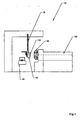
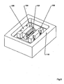
- FIG. 1 a detail of a system 10 for encapsulating a handle 12 of a box 14 can be seen, which is transported along a transport path 16, which may be formed by a conveyor belt, and then inserted by means of a handling device 18 in an injection mold 20, in which the handle 12 overmolded becomes.
- the handle 12 may be one which is present in a side wall of the box 14 but may also be a center handle.
- the injection molding tool 20 is connected to an extruder 22, via which thermoplastic material which is flowable in a known manner is supplied to the injection molding tool 20 or to nozzles present in it.
- the injection molding tool 20 consists solely of a nozzle part without the separate closing part required according to the prior art being required.
- the retention of mold jaws delimiting a cavity in which a portion of the box, so in the embodiment a handle is introduced, in order to be then encapsulated, realized on elements emanating from the nozzle part itself. This will be on hand 4 to 14 explained in more detail.
- the unit consisting of the injection molding tool 20 and the extruder 22 can thereby be made compact, so that use at desired locations can be done easily, so it is not absolutely necessary that the injection mold 20 is used where the box itself is sprayed ,
- this provides the possibility that the molding to be encapsulated or to be sprayed can protrude to a considerable extent over the nozzle part, since a disability is not given by a closing part. Also, a problem-free removal of the molded part from the injection mold 20 can take place, since, as mentioned, a closing part does not have to be previously spaced from the nozzle part in order to be able to remove the molded part from the injection mold.
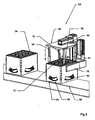
- FIG. 2 is to take a plan view of a system 24 which comprises a plurality of injection molds 26, 28, 30 with associated extruders 32, 34, 36, with which Boxes 38, 40, 42 to be encapsulated to the required extent.
- About handling devices 44, 46, 48, the boxes 38, 40, 42 are inserted into the tools 26, 28, 30 and removed.
- the boxes 38, 40, 42 via a conveyor belt 50 in the required position between the respective handling device 44, 46, 48 and the associated tool 26, 28, 30 moves.
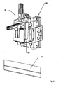
- Fig. 3 is a detail of Annex 10 or 24 refer to. It can be seen on a conveyor belt 52 arranged boxes 54, 56 to be overmolded. In this case, the outer handles 58, 60, middle handles, not shown, or wall sections such as in particular inner wall sections can be encapsulated.
- a handling device 62 which, starting from a pivotable arm 64, comprises a base plate 66 with support bars 68, 70, 72, 74 emanating therefrom, which can be inserted into the corner posts of the box are. Furthermore, the handling device 62 has mutually adjustable side arms 76, 78 to laterally engage the box 56.
- the tool 80 has largely a classic structure with a mold carrier 82 and mold jaws, between which a portion of the box 46 can be introduced to partially surround the portion to be encapsulated by a cavity in the flowable for encapsulation thermoplastic material via a nozzle, not shown is injected.
- a mold carrier 82 and mold jaws, between which a portion of the box 46 can be introduced to partially surround the portion to be encapsulated by a cavity in the flowable for encapsulation thermoplastic material via a nozzle, not shown is injected.
- two corresponding mold jaws in Fig. 4 designated by the reference numerals 84, 86.
- the mold jaws 84, 86 To close the mold jaws 84, 86 and hold or open, ie move away from each other, the mold jaws 84, 86 cooperate with locking wedges 88, 90, are held over the mold jaws 84, 86 in the spray position.
- a closing part is assigned to the nozzle part, via which the locking wedges 88, 90 are locked
- locking takes place without a closing part, resulting in a very compact structural unit for the tool 80.
- the locking or rather locking the mold jaws 84, 86 is technically realized by the fact that the locking wedges 88, 90 in the injection position, ie with closed mold jaws 84, 86 rest on the outside of the forming jaws 84, 86, as in connection with the FIGS. 10 and 11 is explained in more detail.
- FIG. 7 is a schematic view of a section of an injection mold to remove to encase inner wall areas of boxes.
- a mold carrier 92 according to the principal explanations according to the Fig. 4
- Form jaws and associated locking wedges which are exemplified by the reference numerals 94, 96 for the mold jaws and 98, 100 for the locking wedges.
- the mold jaws 94, 96 cooperate in the injection position, ie in the closed mold, in a self-locking manner with the associated locking wedges 98, 100, so that a locking takes place exclusively via the nozzle part of the injection molding tool without the need for a closing part.
- Fig. 8 is shown a section of a tool with which a center handle of a box is overmoulded.
- only two mold jaws 102 and these associated locking wedges 104 are required, which in turn along guide blocks 106, 108 are adjustable to the required movement perpendicular to the mold jaws 102 and the locking wedges 104 receiving mold carrier 110 plane spanned for opening or closing and Locking the mold jaws 102 to be able to adjust.
- a tool 112 which also includes only a nozzle part in which existing handles are to be encapsulated in the side walls of a box.
- the tool 112, that is, the nozzle part comprises a mold carrier 114 with locking wedges which are adjustable perpendicular to the plane which is clamped in front of the latter and by way of which the handles or mold jaws receiving on these adjoining regions of the box are adjustable.
- the guide of the locking wedges 120 takes on an outer wall portion of the mold carrier, ie with respect to the locking wedge 120 of the right wall portion 124 of the mold carrier 114.
- the inner locking wedges 122 are guided via guide jaws, not shown, which may also be sections of the bottom wall 114 of the mold carrier.
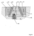
- a section of a nozzle part of an injection mold is shown. It can be seen two mutually adjustable mold jaws 126, 128 and associated therewith locking wedges 130, 132. The directions of movement of the mold jaws 126, 128 and the locking wedges 130, 132 are symbolized by the double arrows.
- the Fig. 10 In closed position, the Fig. 10 can be seen, are the mold jaws 126, 128 on an inner surface each other and enclose a cavity 133 in which a portion of the box 54, 56 to be encapsulated is introduced, in the embodiment of Fig. 10 a side handle.
- the cavity 134 surrounds the side handle in regions spaced so as to overmold remaining cavity with the supplied via a nozzle 136 thermoplastic. This is in particular a softer material compared to the material of the box in order to achieve comfortable wearing properties.
- the locking wedges 130, 132 rest on the outer surfaces of the mold jaws 126, 128 in a self-locking manner. This is the clipping of the Fig. 11 to take closer.
- Fig. 11 is a section of in Fig. 10 shown on the right mold jaw 128 and the associated associated locking wedge 132.
- the mold jaw 128 and the locking wedge 132 are in the closed position over surfaces 134 and 136 self-locking, so that when injecting the plastic material, a pressing apart of the mold jaws 126, 128 is prevented without a separate closing part - as in conventional injection molds - is required.
- the boundary surfaces 134, 136 have a kind of sawtooth structure. This can be realized by successive areas of first, second and third sections.
- a second section 142 extends along the adjustment direction (double arrow 144) of the locking wedge 132.
- a third section 146 which extends extends along a plane which is spanned by the respective surface 134 and 136 of the locking wedge 132 and the forming jaw 128 in the middle, so the overall course of the surface 134 and 136 corresponds. It closes Then areas with corresponding portions 138, 142, 146, to form the tooth structure of the surface 136.
- a corresponding structure has the surface 134 of the mold jaw 128, but with superimposed surfaces 134, 136, the first portions 138, 139 and the third portions 146, 147 spaced from each other.
- the second sections 142, 143 are adjacent to one another in sections.
- self-locking is achieved in the closed position by the second sections 142, 143, wherein the second section 142, 143 does not necessarily have to run parallel to the adjustment direction 144 of the locking wedge 132, but may include an angle ⁇ to the latter, but smaller than 6 °, especially in the range between 5 and 6 °.
- the locking wedge 132 - and thus also the locking wedge 130 - causes not only the locking of the mold jaws 126, 128, but also their movement, ie the moving apart (double arrow 140).
- the locking wedge 132 engages with a cut-T-shaped driver 148 in a corresponding in section T-shaped recesses 150 of the mold jaw 128, as the cutout in Fig. 11a can be seen.
- T-shaped driver 148 is arranged with play in the receptacle 150 so that the opening of the tool initially an adjustment of the locking wedges 130, 132 takes place in the direction of the double arrow 144 without the mold jaws 126, 128 are taken immediately. Only when the driver 148 rests with its transverse leg 152 on the associated locking wedge-side inner surface 154 of the recess 150, the mold jaws 126, 128 are moved along the double arrow 140, whereby the mold can be opened and thus the box or the overmolded handle can be removed.
- the driver 148 is strip-shaped and extends parallel to the averaged from the sections 138, 139, 142, 143, 146, 147 surfaces 134, 136th
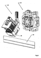
- a tool 156 extend from a holder plate 156, as previously explained, in order to overmold a section of a box, but additionally a second injection tool 158 is composed of a nozzle part 160 and a closing member 162, with which the box itself is injected. After spraying the box and the opening of the tool, the box is inserted by means of a handling device, not shown, in the tool 157, for example, to overmold a center handle.
- the second tool 158 may have a conventional construction to inject boxes, so that it does not require further action.
Landscapes
- Engineering & Computer Science (AREA)
- Manufacturing & Machinery (AREA)
- Mechanical Engineering (AREA)
- Moulds For Moulding Plastics Or The Like (AREA)
- Injection Moulding Of Plastics Or The Like (AREA)
- Processing And Handling Of Plastics And Other Materials For Molding In General (AREA)
- Slide Fasteners, Snap Fasteners, And Hook Fasteners (AREA)
- Diaphragms For Electromechanical Transducers (AREA)
- Pens And Brushes (AREA)
Description
- Die Erfindung bezieht sich auf ein Spritzgießwerkzeug mit einem Düsenteil, das zumindest zwei relativ zueinander verstellbare Formbacken umfasst, die in Spritzstellung einen Hohlraum begrenzen, in dem ein Spritzkanal mündet, sowie zumindest ein mit zumindest einer auf dem Düsenteil verstellbar angeordneten Formbacke wechselwirkendes Schließelement zum Zuhalten der Formbacken in der Spritzstellung, wobei das zumindest eine Schließelement von dem Düsenteil ausgeht und zu diesem verstellbar ausgebildet ist und das Schließelement die zumindest eine Formbacke in ihrer Spritzstellung verriegelt. Ferner nimmt die Erfindung Bezug auf ein Verfahren zum Anspritzen eines Abschnitts an ein Formteil und/oder Umspritzen eines Abschnitts eines Formteil durch Spritzgießen, wobei das Formteil abschnittsweise in einen von zueinander verstellbaren von einem Düsenteil eines Spritzgießwerkzeuges ausgehenden und relativ zueinander verstellbare Formbacken umgebenen Hohlraum eingebracht wird, in den nach Schließen der Formbacken (Spritzstellung) fließfähiges Material gespritzt wird, wobei zumindest eine der Formbacken mittels zumindest eines von dem Düsenteil ausgehenden Schließelements durch Verstellen dieses zu der zumindest einen Formbacke in ihrer Spritzstellung verriegelt wird.
- Aus der
EP-A-1 396 329 sind ein Verfahren und eine Anlage zum Ausbilden eines Abschnitts eines kastenförmigen Behältnisses bekannt. Das verwendete Spritzgießwerkzeug besteht dabei aus einem Düsenteil und einem Spritzteil, über das beim Spritzen die den zu spritzenden Abschnitt des kastenförmigen Behältnisses aufnehmenden Formbacken in der Spritzstellung gehalten werden, um ein Verstellen beim Spritzen auszuschließen. Die Formbacken gehen dabei vom Düsenteil aus. - Der
US-A-3,358,333 ist ein Spritzgießwerkzeug zu entnehmen, mit dem Sohlen an einen Schuhschaft gespritzt werden. Hierzu erforderliche Formbacken werden über Kniehebel verstellt und fixiert, die schwenkbar vom Düsenteil des Werkzeugs ausgehen und über Zylinder betätigbar sind, die ihrerseits an den Rahmen des Gießwerkzeuges angelenkt sind. - Ein aus einem Düsenteil und einem Schließteil bestehendes Spritzgießwerkzeug ist der
US-A-5,422,059 zu entnehmen. Dabei ist das Schließteil zu dem Düsenteil über einen Hydraulikzylinder verstellbar. Das Schließteil wird entlang von Holmen geführt, die vom Düsenteil ausgehen. - Ein aus Düsenteil und Schließteil bestehendes Werkzeug ist auch aus der
DE-A-199 32 515 bekannt. Mit dem entsprechenden Werkzeug lassen sich Kästen mit stabilen Griffen spritzen. - Bei einem Flachenkasten aus Kunststoff nach der
DE-A-40 22 884 kann auf einem Kernelement eines Griffs ein Außenelement aufgespritzt werden. DieEP-A-1 000 865 sieht ein Umspritzen eines Griffs eines Flaschenkastens vor. Gleiches ist derDE-A-102 08 845 zu entnehmen. - Um ein Spritzgussteil herzustellen, sieht die
DE-A-34 46 020 einen von verstellbaren Backen begrenzten Formhohlraum vor, die derart verstellt werden, dass nacheinander unterschiedliche Materialien in den Formhohlraum gespritzt werden können. - Nach der
JP-A-01072815 - Zum Spritzgießen von Kunststoffteilen nach der
JP-A-2001058339 JP-A-08066950 - Der vorliegenden Erfindung liegt das Problem zu Grunde, ein Spritzgießwerkzeug der eingangs genannten Art sowie ein Verfahren derart weiterzubilden, dass bei kompakter Bauart problemlos ein Formteil wie Kasten oder Kraftfahrzeugteil wie Radlaufschale zumindest bereichsweise umspritzt werden kann, um in diesem Bereich gewünschte Materialeigenschaften zu erzielen bzw. das Formteil in einen oder mehreren gewünschten Bereichen geometrisch zu verändern wie zu verlängern. Dabei soll sichergestellt sein, dass die Formbacken beim Spritzen selbsthemmend fixiert sind.
- Das Problem wird durch die Merkmale des Spritzgießwerkzeugs des Anspruchs 1 und des Verfahrens des Anspruchs 6 gelöst.
- Erfindungsgemäß wird das Problem im Wesentlichen dadurch gelöst, dass zum Öffnen bzw. Schließen des Formhohlraums zumindest die eine Formbacke mit dem zumindest einen Schließelement in Form eines Verrlegelungskeils wechselwirkt und die Formbacke und der Verriegelungskeil über geneigt zum Verstellweg des Verriegelungskeils verlaufende strukturierte Flächen sägezahnförmiger Geometrie in Schließstellung kraft- und formschlüssig verbunden sind.
- Es wird ein Spritzgießwerkzeug weitergebildet, bei dem kein gesondertes zu dem Düsenteil verstellbares Schließteil erforderlich ist, um die Formbacken während des Spritzens zu sichern, also zuzuhalten. Somit ist das Düsenteil während des Spritzens von einem Schließteil nicht abgedeckt, so dass problemlos ein Abschnitt des Formteils umspritzt bzw. ein Abschnitt an das Formteil angespritzt werden kann. Bei dem Formteil kann es sich z. B. um einen Kasten oder ein Kraftfahrzeugteil wie Radlaufschale oder einen Unterboden handeln, so dass das Formteil in erheblichem Umfang aus dem Werkzeug vorsteht, eine Möglichkeit, die klassische Spritzgießwerkzeuge nicht bieten, bei denen die von dem Düsenteil ausgehenden Formbacken über ein gesondertes zu den Formbacken verstellbares Düsenteil verriegelt werden. Zum Entfernen des hergestellten Spritzgussteils muss das Schließteil zu dem Düsenteil in einem Umfang beabstandet werden, dass das Formteil aus dem Zwischenraum zwischen Düsenteil und Schließteil entfernt werden kann. Hierzu müssen Düsenteil und Schließteil axial derart zueinander beabstandet werden, dass der lichte Abstand größer als Erstreckung des Spritzgussteils in axialer Richtung ist.
- Von dem Düsenteil geht das zum Zuhalten des bzw. der Formbacken erforderliche verstellbare Schließelement aus, so dass ein überaus kompaktes Spritzgießwerkzeug zur Verfügung gestellt wird, das folglich ohne großen maschinellen Aufwand dort zum Einsatz gelangen kann, wo z. B. ein Abschnitt eines Formteils wie Kastens umspritzt werden soll. Insbesondere besteht erwähntermaßen der Vorteil, dass das zu umspritzende bzw. anzuspritzende Formteil in erheblichem Umfang über das Düsenteil vorstehen kann.
- Selbstverständlich beschränkt sich die erfindungsgemäße Lehre nicht allein auf ein Spritzgießwerkzeug, mit dem ein Formteil bzw. ein Abschnitt eines solchen umspritzt bzw. ein Abschnitt aufgespritzt werden kann. Vielmehr ist die Lehre auch prinzipiell zum Spritzen von Formteilen an sich geeignet.
- Erfindungsgemäß ist vorgesehen, dass die Formbacke mit zumindest einem Schließelement in Form eines Verriegelungskeils wechselwirkt, wobei die Formbacke und der Verriegelungskeil in Schließstellung über geneigt zum Verstellweg des Verriegelungskeils verlaufende strukturierte Flächen kraft- und formschlüssig verbunden sind, um auf diese Weise die Selbsthemmung zu realisieren. Dabei weisen die aufeinander liegenden Flächen insbesondere eine sägezahnförmige Geometrie auf.
- Vorzugsweise weist die Fläche mehrere zumindest einen ersten, einen zweiten und einen dritten Abschnitt umfassende Bereiche auf, wobei sich der erste Abschnitt quer zum Verstellweg des Verriegelungskeils, der zweite Abschnitt sich in Richtung des Verstellwegs des Verriegelungskeils und der die Abschnitte verbindende dritte Abschnitt entlang von von der strukturierten Fläche aufgespannter Ebene erstrecken. Durch eine diesbezügliche Geometrie ist sichergestellt, dass in der Schließstellung die aufeinander liegenden Flächen von Formbacke und Verriegelungskeil derart zueinander abgestützt sind, dass die erforderliche Selbsthemmung mit der Folge auftritt, dass beim Spritzen ein Auseinanderbewegen der Formbacken ausgeschlossen ist.
- Dabei kann die Reihenfolge der Abschnitte auch voneinander abweichen. Ferner verlaufen die ersten und dritten Abschnitte der aufeinander liegenden Flächen von Verriegelungskeil und Formbacke stets zueinander beabstandet.
- Verlaufen die zweiten Abschnitte der die sägezahnförmige Geometrie bildenden Bereiche der sich aufeinander abstützenden Flächen von Formbacke und Verriegelungskeil vorzugsweise parallel zum Verstellweg des Verriegelungskeils, so kann der zweite Abschnitt auch zum Verstellweg einen Winkel α mit insbesondere α ≤ 6°, vorzugsweise 5° ≤ α ≤ 6° einschließen.
- Um über den Verriegelungskeil die Formbacken beim Öffnen des Werkzeugs mitzunehmen, ist vorgesehen, dass von dem Verriegelungskeil zumindest ein in die Formbacke eingreifender Mitnehmer ausgeht, wobei zum Entriegeln der Formbacke der Verriegelungskeil zu dieser mit Spiel verstellbar ist. Mit anderen Worten erfolgt zunächst ein Bewegen des Verriegelungskeils, um sodann die Formbacke mitzunehmen. Hierdurch ist sichergestellt, dass beim Schließen des Verriegelungskeils der erforderliche Formschluss zur Formbacke erreichbar ist.
- Insbesondere geht von dem Verriegelungskeil ein entlang dessen mit der Formbacke wechselwirkender Fläche verlaufender im Schnitt T-förmiger Mitnehmer aus, dessen Querschenkel mit Spiel in eine in Längsrichtung der mit dem Verriegelungskeil wechselwirkenden Fläche verlaufende Aussparung eingreift.
- Mit anderen Worten weist die Formbacke in ihrem dem Verriegelungskeil zugewandten Bereich eine im Schnitt T-förmige Aussparung auf, in die mit Spiel der T-förmigen Mitnehmer verläuft.
- Der von den Formbacken umgebene Hohlraum zum Umspritzen eines Abschnitts eines Formteils ist des Weiteren derart ausgebildet, dass der Hohlraum zumindest abschnittsweise beabstandet den zu umspritzenden Abschnitt umgibt. Gegebenenfalls kann der Hohlraum auch umlaufend den Abschnitt beabstandet umgeben.
- Soll ein Abschnitt an ein Formteil angespritzt werden, so ist die Erstreckung des Bereichs des Formteils innerhalb des Hohlraums, an den der Abschnitt angespritzt werden soll, häufig erheblich kleiner als der verbleibende Raum, in den das schmelzflüssige Material gespritzt wird.
- Unabhängig hiervon besteht die Möglichkeit, problemlos Verstärkungen an vorhandene Formteile anzuspritzen bzw. Griffe wie Griffe von Kästen zu erneuern bzw. mit einer Oberfläche bzw. Außenschicht zu versehen, die den Tragekomfort erhöht.
- Des Weiteren zeichnet sich die Erfindung durch ein Verfahren zum Anspritzen eines Abschnitts an ein Formteil und/oder Umspritzen eines Abschnitts eines Formteil durch Spritzgießen, wobei das Formteil abschnittsweise in einen von zueinander verstellbaren von einem Düsenteil eines Spritzgießwerkzeuges ausgehenden und relativ zueinander verstellbare Formbacken umgebenen Hohlraum eingebracht wird, in den nach Schließen der Formbacken (Spritzstellung) fließfähiges Material gespritzt wird, wobei zumindest eine der Formbacken mittels zumindest eines von dem Düsenteil ausgehenden Schließelements durch Verstellen dieses zu der zumindest einen Formbacke in ihrer Spritzstellung verriegelt wird, dadurch aus, dass die zumindest eine Formbacke mit dem zumindest einen Schließelement durch formschlüssiges Eingreifen des Verriegelungselementes in die Formbacke verriegelt wird.
- Weitere Einzelheiten, Vorteile und Merkmale der Erfindung ergeben sich nicht nur aus den Ansprüchen, den diesen zu entnehmenden Merkmalen - für sich und/oder in Kombination - sondern auch aus der nachfolgenden Beschreibung von der Zeichnung zu entnehmenden bevorzugten Ausführungsbeispiele.
- Es zeigen:
- Fig. 1
- eine Seitenansicht einer Anordnung zum Umspritzen eines Abschnitts eines Formteils bzw. Anspritzen eines Abschnitts an ein Formteil,
- Fig. 2
- eine Draufsicht auf eine Anlage zum Umspritzen bzw. Anspritzen von Abschnitten von bzw. an Formteilen,
- Fig. 3
- einen Ausschnitt aus einer Anlage zum Umspritzen bzw. Anspritzen von Abschnitten von bzw. an Formteilen in Form von Kästen,
- Fig. 4
- die Handhabungseinrichtung gemäß
Fig. 3 mit auf ein Spritzgießwerkzeug ausgerichtetem Formteil, - Fig. 5
- das Formteil gemäß
Fig. 4 bei in das Spritzgießwerkzeug eingebrachter Position, - Fig. 6
- das Formteil gemäß
Fig. 4 und5 nach Umspritzen bzw. Anspritzen und Entfernen aus dem Spritzgießwerkzeug. - Fig. 7
- einen Ausschnitt eines Spritzgießwerkzeuges zum Umspritzen einer Innenwandung eines Formteils,
- Fig. 8
- einen Ausschnitt eines Spritzgießwerkzeuges zum Umspritzen eines Mittelhandgriffs eines Formteils,
- Fig. 9
- einen Ausschnitt eines Spritzgießwerkzeuges zum Umspritzen von Außenhandgriffen eines Formteils,
- Fig. 10
- einen Ausschnitt einer der erfindungsgemäßen Lehre gehorchenden Ausführungsform eines Spritzgießwerkzeuges,
- Fig. 11
- einen Ausschnitt aus der Anordnung gemäß
Fig. 10 , - Fig. 11a
- ein Detail des Werkzeugs gemäß
Fig. 10 und - Fig. 12
- eine weitere Ausführungsform einer Anordnung zum Spritzen eines Formteils sowie zum Umspritzen eines Abschnitts des Formteils.
- Anhand der nachfolgenden Beschreibung der
Figuren 1 bis 12 sollen bevorzugte Ausgestaltungen bzw. Anordnungen und Ausschnitte von Anlagen zum Spritzen von Formteilen bzw. zum Umspritzen von Abschnitten von Formteilen bzw. Anspritzen von Abschnitten von Formteilen erläutert werden. Dabei wird aus Gründen der Vereinfachung von einem Flaschenkasten als Formteil ausgegangen, ohne dass hierdurch die erfindungsgemäße Lehre eingeschränkt werden soll. Als Formteil kann jeder Gegenstand aus einem geeigneten Material benutzt werden, an den ein Abschnitt angespritzt bzw. ein Abschnitt umspritzt werden kann. Dabei wird grundsätzlich beim Anspritzen eines Abschnitts ein Abschnitt des Formteils selbst zumindest abschnittsweise umspritzt. Selbstverständlich bestünde auch die Möglichkeit, sofern dies von den Materialien einerseits und von den Herstellungsbedingungen und Produktionsanforderungen andererseits gegeben ist, den Abschnitt an das Formteil im Stoß zu verbinden. - Als Formteile kommen insbesondere auch Kunststoffteile der Kraftfahrzeugindustrie wie Radlaufschalen oder Kraftfahrzeugunterbodenverkleidungen in Frage, um nur beispielhaft einige Gegenstände zu nennen.
- Auch wird nachstehend die Erfindung anhand des Umspritzens eines Griffs eines Flaschenkastens erläutert, ohne dass dies als Einschränkung der Erfindung zu verstehen ist. Vielmehr gelten gleiche Erläuterungen für das Anspritzen eines Abschnitts an ein Formteil wie Flaschenkasten.
- Der
Fig. 1 ist ein Ausschnitt einer Anlage 10 zum Umspritzen eines Griffs 12 eines Kastens 14 zu entnehmen, der entlang einer Transportbahn 16, die durch ein Förderband gebildet sein kann, transportiert und sodann mittels einer Handhabungseinrichtung 18 in ein Spritzgießwerkzeug 20 eingesetzt, in dem der Griff 12 umspritzt wird. - Bei dem Griff 12 kann es sich um einen solchen handeln, der in einer Seitenwandung des Kastens 14 vorhanden ist, aber auch um einen Mittelhandgriff handeln.
- Das Spritzgießwerkzeug 20 ist mit einem Extruder 22 verbunden, über den in bekannter Weise fließfähiger thermoplastischer Kunststoff dem Spritzgießwerkzeug 20 bzw. in diesem vorhandenen Düsen zugeführt wird. Dabei besteht erfindungsgemäß das Spritzgießwerkzeug 20 allein aus einem Düsenteil, ohne dass das nach dem Stand der Technik erforderliche gesonderte Schließteil erforderlich ist. Somit wird die Zuhaltung von Formbacken, die einen Hohlraum begrenzen, in dem ein Abschnitt des Kastens, also im Ausführungsbeispiel ein Griff eingebracht wird, um sodann umspritzt zu werden, über Elemente realisiert, die vom Düsenteil selbst ausgehen. Dies wird an Hand der
Fig. 4 bis 14 näher erläutert. - Die Einheit bestehend aus dem Spritzgießwerkzeug 20 und dem Extruder 22 kann hierdurch kompakt aufgebaut werden, so dass ein Einsatz an gewünschten Orten problemlos erfolgen kann, es also nicht zwingend erforderlich ist, dass das Spritzgießwerkzeug 20 dort zum Einsatz gelangt, wo der Kasten selbst gespritzt wird.
- Hierdurch besteht die Möglichkeit, dass zum Beispiel Kästen in einer Flaschenabfüllanlage, von der aus die Flaschen in die Kästen eingesetzt werden, umspritzt werden können, so dass auch ein nachträgliches Umspritzen von bereits im Einsatz befindlichen Kästen möglich ist.
- Insbesondere ist hierdurch die Möglichkeit gegeben, dass das zu umspritzende bzw. anzuspritzende Formteil in erheblichem Umfang über das Düsenteil vorstehen kann, da eine Behinderung durch ein Schließteil nicht gegeben ist. Auch kann ein problemloses Entfernen des Formteils aus dem Spritzgießwerkzeug 20 erfolgen, da erwähntermaßen ein Schließteil nicht zuvor von dem Düsenteil beabstandet werden muss, um das Formteil aus dem Spritzgießwerkzeug herausnehmen zu können.
- Der
Fig. 2 ist eine Draufsicht auf eine Anlage 24 zu entnehmen, die mehrere Spritzgießwerkzeuge 26, 28, 30 mit zugeordneten Extrudern 32, 34, 36 umfasst, mit denen Kästen 38, 40, 42 im erforderlichen Umfang umspritzt werden sollen. Über Handhabungseinrichtungen 44, 46, 48 werden die Kästen 38, 40, 42 in die Werkzeuge 26, 28, 30 eingesetzt bzw. diesen entnommen. Hierzu werden die Kästen 38, 40, 42 über ein Förderband 50 in die erforderliche Position zwischen der jeweiligen Handhabungseinrichtung 44, 46, 48 und dem zugeordneten Werkzeug 26, 28, 30 bewegt. - Der
Fig. 3 ist ein Detail der Anlage 10 bzw. 24 zu entnehmen. Man erkennt auf einem Förderband 52 angeordnete Kästen 54, 56, die umspritzt werden sollen. Dabei können die Außengriffe 58, 60, nicht dargestellte Mittelhandgriffe oder auch Wandabschnitte wie insbesondere Innenwandabschnitte umspritzt werden. - Damit der jeweilige Kasten 54, 56 in ein Spritzgießwerkzeug eingesetzt wird, ist eine Handhabungseinrichtung 62 vorgesehen, die von einem verschwenkbaren Arm 64 ausgehend eine Basisplatte 66 mit von diesem ausgehende Stützholmen 68, 70, 72, 74 umfasst, die in die Eckholme des Kastens einsetzbar sind. Ferner weist die Handhabungseinrichtung 62 zueinander verstellbare Seitenarme 76, 78 auf, um den Kasten 56 seitlich zu erfassen.
- Sobald die Holme 68, 72, 74 in die Eckholme des Kastens 56 eingefahren sind, wird der Arm 64 derart verschwenkt, dass der Kasten 56 mit seiner offenen Seite auf ein Werkzeug 80 ausgerichtet und in dieses eingesetzt wird. Das Werkzeug 80 weist weitgehend einen klassischen Aufbau mit einem Formenträger 82 sowie Formbacken auf, zwischen denen ein Abschnitt des Kastens 46 einbringbar ist, um bereichsweise den zu umspritzenden Abschnitt von einem Hohlraum zu umgeben, in den zum Umspritzen fließfähiger thermoplastischer Kunststoff über eine nicht dargestellte Düse eingespritzt wird. Rein beispielhaft werden zwei entsprechende Formbacken in
Fig. 4 mit dem Bezugszeichen 84, 86 gekennzeichnet. - Um die Formbacken 84, 86 zu schließen und zuzuhalten bzw. zu öffnen, also voneinander weg zu bewegen, wirken die Formbacken 84, 86 mit Verriegelungskeilen 88, 90 zusammen, über die Formbacken 84, 86 in der Spritzstellung zugehalten werden.
- Der Formenträger 82 mit den Formbacken 84, 86 und den Verriegelungskeilen 88, 90 sowie die in dem Formenträger 82 vorhandenen, jedoch nicht näher bezeichneten bzw. dargestellten Düsen stellen folglich das Düsenteil des Werkzeugs 80 dar.
- Ist nach dem Stand der Technik dem Düsenteil ein Schließteil zugeordnet, über das die Verriegelungskeile 88, 90 verriegelt werden, so ist erfindungsgemäß vorgesehen, dass ein Verriegeln ohne ein Schließteil erfolgt, wodurch sich eine überaus kompakte Baueinheit für das Werkzeug 80 ergibt. Das Verriegeln oder besser gesagt das Zuhalten der Formbacken 84, 86 wird dabei technisch dadurch realisiert, dass die Verriegelungskeile 88, 90 in der Spritzstellung, also bei geschlossenen Formbacken 84, 86 selbsthemmend außenseitig an den Formbacken 84, 86 anliegen, wie im Zusammenhang mit den
Figuren 10 und 11 näher erläutert wird. - Nach Umspritzen des oder der Abschnitte des Kastens 56 und nach Öffnen der Formbacken 84, 86, also Auseinanderfahren dieser durch Verstellen der Verriegelungskeile 88, 90 senkrecht zu der von dem Formenträger 82 aufgespannten Ebene wird der Kasten 56 aus dem Werkzeug 80 über die Handhabungseinrichtung 62 entnommen, die die Funktion der Auswerfereinheit übernimmt. Sodann wird der Kasten 56 auf das Förderband 52 zurückgestellt, um anschließend den nachfolgenden Kasten, also gemäß der Darstellung in
Fig. 3 den Kasten 54 in das Werkzeug 80 einzusetzen. - Der
Fig. 7 ist in Prinzipdarstellung ein Ausschnitt eines Spritzgießwerkzeuges zu entnehmen, um Innenwandbereiche von Kästen zu umspritzen. Hierzu gehen von einem Formenträger 92 entsprechend der prinzipiellen Erläuterungen gemäß derFig. 4 Formbacken und zugeordnete Verriegelungskeile aus, die beispielhaft mit den Bezugszeichen 94, 96 für die Formbacken und 98, 100 für die Verriegelungskeile bezeichnet sind. Die Formbacken 94, 96 wirken in Spritzstellung, also bei geschlossener Form, selbsthemmend mit den zugeordneten Verriegelungskeilen 98, 100 zusammen, so dass eine Verriegelung ausschließlich über das Düsenteil des Spritzgießwerkzeuges erfolgt, ohne dass es eines Schließteils bedarf. - In
Fig. 8 ist ein Ausschnitt eines Werkzeuges dargestellt, mit dem ein Mittelhandgriff eines Kastens umspritzt wird. Dabei sind allein zwei Formbacken 102 und diesen zugeordneten Verriegelungskeilen 104 erforderlich, die ihrerseits entlang von Führungsböcken 106, 108 verstellbar sind, um die erforderliche Bewegung senkrecht zur von einem die Formbacken 102 und die Verriegelungskeile 104 aufnehmenden Formenträger 110 aufgespannten Ebene zum Öffnen bzw. Schließen und Zuhalten der Formbacken 102 verstellen zu können. - In der
Fig. 9 ist rein prinzipiell ein Werkzeug 112 dargestellt, das ebenfalls ausschließlich ein Düsenteil umfasst, in dem in den Seitenwandungen eines Kastens vorhandene Griffe umspritzt werden sollen. Das Werkzeug 112, also das Düsenteil, umfasst einen Formenträger 114 mit senkrecht zu der vor diesem aufgespannten Ebene verstellbaren Verriegelungskeilen, über die die Handgriffe bzw. sich an diese anschließende Bereiche des Kastens aufnehmenden Formbacken verstellbar sind. - Beispielhaft sind zwei einander zugeordnete Formbacken mit den Bezugszeichen 116, 118 und die entsprechenden diese führenden und zuhaltenden Verriegelungskeile mit den Bezugszeichen 120, 122 gekennzeichnet. Die Führung der Verriegelungskeile 120 übernimmt dabei ein Außenwandabschnitt des Formenträgers, also in Bezug auf den Verriegelungskeil 120 der rechte Wandabschnitt 124 des Formenträgers 114. Die inneren Verriegelungskeile 122 werden über nicht dargestellte Führungsbacken geführt, die auch Abschnitte der Bodenwandung des Formenträgers 114 sein können.
- Um ohne Schließteil die Formbacken in Spritzstellung zuzuhalten, ist erfindungsgemäß ein selbsthemmendes Anliegen der Verriegelungskeile an den Formbacken gegeben, wie dies prinzipiell anhand der
Fig. 10 und11 erläutert werden soll. Andere technische Realisierungsmöglichkeiten zur Erreichung einer Selbsthemmung sind selbstverständlich gleichfalls möglich. - In der
Fig. 10 ist ein Ausschnitt eines Düsenteils eines Spritzgießwerkzeuges dargestellt. Man erkennt zwei zueinander verstellbare Formbacken 126, 128 und diesen zugeordnete Verriegelungskeile 130, 132. Die Bewegungsrichtungen von den Formbacken 126, 128 bzw. den Verriegelungskeilen 130, 132 sind durch die Doppelpfeile symbolisiert. In Schließstellung, der derFig. 10 zu entnehmen ist, liegen die Formbacken 126, 128 über eine innere Fläche aufeinander und umschließen einen Hohlraum 133, in dem ein zu umspritzender Abschnitt des Kastens 54, 56 eingebracht wird, und zwar im Ausführungsbeispiel derFig. 10 ein Seitenhandgriff. Dabei umgibt der Hohlraum 134 den Seitenhandgriff bereichsweise beabstandet, um so verbliebenen Hohlraum mit dem über eine Düse 136 zuzuführenden thermoplastischen Kunststoff zu umspritzen. Hierbei handelt es sich insbesondere um ein im Vergleich zu dem Material des Kastens weicheres Material, um angenehme Trageigenschaften zu erzielen. - Um beim Spritzen sicherzustellen, dass die Formbacken 126, 128 nicht auseinandergedrückt werden, also die Formbacken 126, 128 verriegelt oder zugehalten werden, liegen die Verriegelungskeile 130, 132 selbsthemmend an den Außenflächen der Formbacken 126, 128 an. Dies ist dem Ausschnitt der
Fig. 11 näher zu entnehmen. - In
Fig. 11 ist ein Abschnitt der inFig. 10 rechts dargestellten Formbacke 128 und des dieser zugeordneten Verriegelungskeils 132 dargestellt. Die Formbacke 128 und der Verriegelungskeil 132 liegen in Schließstellung über Flächen 134 und 136 selbsthemmend aufeinander, so dass beim Einspritzen des Kunststoffmaterials ein Auseinanderdrücken der Formbacken 126, 128 verhindert wird, ohne dass ein gesondertes Schließteil - wie bei üblichen Spritzgießwerkzeugen - erforderlich ist. - Um die Selbsthemmung zu realisieren, weisen die Begrenzungsflächen 134, 136 eine Art Sägezahnstruktur auf. Diese kann durch aufeinander folgende Bereiche von ersten, zweiten und dritten Abschnitten realisiert werden. So verläuft ein erster Abschnitt 138 entlang Verstellrichtung (Doppelpfeil 140) der Formbacke 128. Ein zweiter Abschnitt 142 erstreckt sich entlang Verstellrichtung (Doppelpfeil 144) des Verriegelungskeils 132. Zwischen dem ersten Abschnitt 138 und dem zweiten Abschnitt 142 verläuft ein dritter Abschnitt 146, der sich entlang einer Ebene erstreckt, die von der jeweiligen Fläche 134 bzw. 136 des Verriegelungskeils 132 bzw. der Formbacke 128 im Mittel aufgespannt wird, also dem Gesamtverlauf der Fläche 134 bzw. 136 entspricht. Es schließt sich sodann Bereiche mit entsprechenden Abschnitten 138, 142, 146 an, um die Zahnstruktur der Fläche 136 zu bilden.
- Eine entsprechende Struktur weist die Fläche 134 der Formbacke 128 auf, wobei jedoch bei aufeinander liegenden Flächen 134, 136 die ersten Abschnitte 138, 139 und die dritten Abschnitte 146, 147 zueinander beabstandet verlaufen. Die zweiten Abschnitte 142, 143 liegen demgegenüber abschnittsweise aufeinander. Hierdurch wird in Schließstellung durch die zweiten Abschnitte 142, 143 eine Selbsthemmung erzielt, wobei der zweite Abschnitt 142, 143 nicht zwingend parallel zur Verstellrichtung 144 des Verriegelungskeils 132 verlaufen muss, sondern zu dieser einen Winkel α einschließen kann, der jedoch kleiner als 6°, insbesondere im Bereich zwischen 5 und 6° liegen sollte.
- Der Verriegelungskeil 132 - und somit auch der Verriegelungskeil 130 - bewirkt nicht nur das Zuhalten der Formbacken 126, 128, sondern auch deren Bewegung, also das Auseinanderfahren (Doppelpfeil 140). Um dies ungeachtet der zu realisierenden Selbsthemmung zu ermöglichen, greift der Verriegelungskeil 132 mit einem im Schnitt T-förmigen Mitnehmer 148 in eine entsprechende im Schnitt T-förmige Ausnehmungen 150 der Formbacke 128 ein, wie dem Ausschnitt in
Fig. 11a zu entnehmen ist. Dabei ist der entlang der Flächen 134, 136 verlaufende T-förmige Mitnehmer 148 mit Spiel in der Aufnahme 150 angeordnet, so dass zum Öffnen des Werkzeuges zunächst ein Verstellen der Verriegelungskeile 130, 132 in Richtung des Doppelpfeils 144 erfolgt, ohne dass die Formbacken 126, 128 unmittelbar mitgenommen werden. Erst wenn der Mitnehmer 148 mit seinem Querschenkel 152 an zugeordneter verriegelungskeilseitig verlaufender Innenfläche 154 der Ausnehmung 150 anliegt, werden die Formbacken 126, 128 entlang des Doppelpfeils 140 bewegt, wodurch die Form geöffnet und somit der Kasten bzw. der umspritzte Handgriff entnommen werden kann. Dabei ist der Mitnehmer 148 leistenförmig ausgebildet und erstreckt sich parallel entlang der aus den Abschnitten 138, 139, 142, 143, 146, 147 gemittelten Flächen 134, 136. - Gemäß
Fig. 12 geht von einer Halterplatte 156 nicht nur ein Werkzeug aus, wie dies zuvor erläutert worden ist, um einen Abschnitt eines Kastens zu umspritzen, sondern zusätzlich ist ein zweites Spritzgießwerkzeug 158 bestehend aus einem Düsenteil 160 und einem Schließteil 162 vorhanden, mit dem der Kasten selbst gespritzt wird. Nach dem Spritzen des Kastens und dem Öffnen des Werkzeuges wird der Kasten mittels einer nicht dargestellten Handhabungseinrichtung in das Werkzeug 157 eingesetzt, um zum Beispiel einen Mittelhandgriff zu umspritzen. Das zweite Werkzeug 158 kann dabei eine übliche Konstruktion aufweisen, um Kästen zu spritzen, so dass es eines weiteren Eingehens nicht bedarf.
Claims (6)
- Spritzgießwerkzeug (20, 80, 112) mit einem Düsenteil (200), das zumindest zwei relativ zueinander verstellbare Formbacken (126, 128) umfasst, die in Spritzstellung einen Hohlraum (133) begrenzen, in dem ein Spritzkanal mündet, sowie zumindest ein mit zumindest einer auf dem Düsenteil verstellbar angeordneten Formbacke wechselwirkendes Schließelement (130, 132) zum Zuhalten der Formbacken in der Spritzstellung, wobei das zumindest eine Schließelement (130, 132) von dem Düsenteil ausgeht und zu diesem verstellbar ausgebildet ist und das Schließelement die zumindest eine Formbacke (126, 128) in ihrer Spritzstellung verriegelt,
dadurch gekennzeichnet,
dass zum Öffnen bzw. Schließen des Formhohlraums (133) zumindest die eine Formbacke (126, 128) mit dem zumindest einen Schließelement in Form eines Verriegelungskeils (130, 132) wechselwirkt und die Formbacke (126, 128) und der Verriegelungskeil (130, 132) über geneigt zum Verstellweg (144) des Verriegelungskeils verlaufende strukturierte Flächen (134, 136) sägezahnförmiger Geometrie in Schließstellung kraft- und formschlüssig verbunden sind. - Spritzgießwerkzeug nach Anspruch 1,
dadurch gekennzeichnet,
dass der Formhohlraum (133) von zumindest zwei Formbacken (126, 128) begrenzt ist und dass jede Formbacke mit zumindest einem Schließelement in Form des Verriegelungskeils (130, 132) wechselwirkt. - Spritzgießwerkzeug nach Anspruch 1 oder 2,
dadurch gekennzeichnet,
dass die Fläche (134, 136) mehrere zumindest einen ersten, einen zweiten und einen dritten Abschnitt (138, 139, 142, 143, 146, 147) umfassende Bereiche aufweist, dass der erste Abschnitt (138, 139) sich quer zum Verstellweg (144) des Verriegelungskeils (132), der zweite Abschnitt (142, 143) sich in Richtung des Verstellwegs des Verriegelungskeils und der diese verbindende dritte Abschnitt (146, 147) entlang von von der Fläche (134, 136) aufgespannter Ebene erstrecken, wobei der zweite Abschnitt (142, 143) parallel zum Verstellweg (144) des Verriegelungskeils (132) oder unter einem Winkel α mit insbesondere α ≤ 6°, vorzugsweise 5° ≤ α ≤ 6° zum Verstellweg (144) verläuft. - Spritzgießwerkzeug nach zumindest einem der vorhergehenden Ansprüche,
dadurch gekennzeichnet,
dass von dem Verriegelungskeil (132) zumindest ein in die Formbacke (128) eingreifender Mitnehmer (148) ausgeht, wobei zum Entriegeln der Formbacke der Verriegelungskeil zu dieser mit Spiel verstellbar ist, insbesondere von dem Verriegelungskeil (132) ein entlang dessen mit der Formbacke (128) wechselwirkender Fläche (134, 136) verlaufender im Schnitt T-förmiger Mitnehmer (148) ausgeht, dessen Querschenkel (152) mit Spiel in eine in Längsrichtung der mit dem Verriegelungskeil wechselwirkenden Fläche verlaufende Aussparung (150) eingreift. - Spritzgießwerkzeug nach zumindest einem der Ansprüche 1 bis 4,
dadurch gekennzeichnet,
dass die Formbacken (126, 128) von einem Formträger des Spritzgießwerkzeuges ausgehen und dass das zumindest eine Schließelement (130, 132) verstellbar, insbesondere über einen Druckzylinder verstellbar mit dem Formträger verbunden ist. - Verfahren zum Anspritzen eines Abschnitts an ein Formteil und/oder Umspritzen eines Abschnitts eines Formteil durch Spritzgießen, wobei das Formteil abschnittsweise in einen von zueinander verstellbaren von einem Düsenteil eines Spritzgießwerkzeuges nach zumindest einem der Ansprüche 1-5 ausgehenden und relativ zueinander verstellbare Formbacken umgebenen Hohlraum eingebracht wird, in den nach Schließen der Formbacken in der Spritzstellung fließfähiges Material gespritzt wird, wobei zumindest eine der Formbacken mittels zumindest eines von dem Düsenteil ausgehenden Schließelements durch Verstellen dieses zu der zumindest einen Formbacke in ihrer Spritzstellung verriegelt wird, wobei
die zumindest eine Formbacke mit dem zumindest einen Schließelement durch formschlüssiges Eingreifen des Verriegelungselementes in die Formbacke verriegelt wird.
Priority Applications (3)
| Application Number | Priority Date | Filing Date | Title |
|---|---|---|---|
| PL05014892T PL1632329T3 (pl) | 2004-07-10 | 2005-07-08 | Forma wtryskowa i sposób wtryskowego formowania segmentów kształtek |
| EP08168031A EP2017059B1 (de) | 2004-07-10 | 2005-07-08 | Spritzgiesswerkzeug und Verfahren zum Spritzen eines Abschnitts eines Formteils |
| PL08168031T PL2017059T3 (pl) | 2004-07-10 | 2005-07-08 | Forma wtryskowa i sposób wtryskowego formowania kształtek |
Applications Claiming Priority (1)
| Application Number | Priority Date | Filing Date | Title |
|---|---|---|---|
| DE102004033461A DE102004033461A1 (de) | 2004-07-10 | 2004-07-10 | Spritzgießwerkzeug sowie Anlage zum Spritzen eines Abschnitts eines Kastens |
Related Child Applications (1)
| Application Number | Title | Priority Date | Filing Date |
|---|---|---|---|
| EP08168031A Division EP2017059B1 (de) | 2004-07-10 | 2005-07-08 | Spritzgiesswerkzeug und Verfahren zum Spritzen eines Abschnitts eines Formteils |
Publications (3)
| Publication Number | Publication Date |
|---|---|
| EP1632329A2 EP1632329A2 (de) | 2006-03-08 |
| EP1632329A3 EP1632329A3 (de) | 2006-12-13 |
| EP1632329B1 true EP1632329B1 (de) | 2008-11-12 |
Family
ID=35501447
Family Applications (2)
| Application Number | Title | Priority Date | Filing Date |
|---|---|---|---|
| EP05014892A Expired - Lifetime EP1632329B1 (de) | 2004-07-10 | 2005-07-08 | Spritzgiesswerkzeug und Verfahren zum Spritzen eines Abschnitts eines Formteils |
| EP08168031A Expired - Lifetime EP2017059B1 (de) | 2004-07-10 | 2005-07-08 | Spritzgiesswerkzeug und Verfahren zum Spritzen eines Abschnitts eines Formteils |
Family Applications After (1)
| Application Number | Title | Priority Date | Filing Date |
|---|---|---|---|
| EP08168031A Expired - Lifetime EP2017059B1 (de) | 2004-07-10 | 2005-07-08 | Spritzgiesswerkzeug und Verfahren zum Spritzen eines Abschnitts eines Formteils |
Country Status (6)
| Country | Link |
|---|---|
| EP (2) | EP1632329B1 (de) |
| AT (2) | ATE413959T1 (de) |
| DE (3) | DE102004033461A1 (de) |
| ES (2) | ES2317108T3 (de) |
| PL (2) | PL2017059T3 (de) |
| PT (2) | PT1632329E (de) |
Families Citing this family (8)
| Publication number | Priority date | Publication date | Assignee | Title |
|---|---|---|---|---|
| DE102005059976B4 (de) | 2005-12-13 | 2019-10-17 | Delbrouck Gmbh | Verfahren und Spritzgußform zur Herstellung eines Transportkastens aus Kunststoff |
| DE102007047922A1 (de) | 2007-12-12 | 2009-06-18 | Icos Gmbh | Flaschenkasten |
| DE102008015382A1 (de) * | 2008-03-20 | 2009-09-24 | Linpac Allibert Gmbh | Einstückig aus Kunststoff hergestellter Flaschenträger und zu seiner Herstellung dienendes Formwerkzeug |
| DE102008002985A1 (de) | 2008-08-01 | 2010-02-11 | Icos Gmbh | Spritzgießvorrichtung sowie Verfahren zum Spritzgießen |
| DE102013227054A1 (de) * | 2013-12-23 | 2015-06-25 | Robert Bosch Gmbh | Stator mit einer Umspritzung und elektrische Maschine mit dem Stator |
| DE102016122077A1 (de) * | 2016-11-17 | 2018-05-17 | Schoeller Allibert Gmbh | Verfahren und Vorrichtung zur Labelanordnung auf einem Kasten, insbesondere Flaschenkasten |
| JP7053063B1 (ja) * | 2020-10-20 | 2022-04-12 | 株式会社国盛化学 | 成型システム |
| CN112406041B (zh) * | 2020-10-30 | 2022-08-30 | 石招军 | 一种抽芯长度可调的注塑模具 |
Family Cites Families (15)
| Publication number | Priority date | Publication date | Assignee | Title |
|---|---|---|---|---|
| FR1076318A (fr) * | 1953-03-10 | 1954-10-26 | Perfectionnements aux moules pour pièces circulaires réalisées en matière plastique | |
| US3358333A (en) * | 1965-04-30 | 1967-12-19 | United Shoe Machinery Corp | Two-station injection sole molding machines |
| DE3446020A1 (de) * | 1984-12-17 | 1986-06-19 | Peguform-Werke GmbH, 7805 Bötzingen | Verfahren zur herstellung von spritzgussteilen aus kunststoff |
| JPS6472815A (en) * | 1987-09-14 | 1989-03-17 | Ricoh Kk | Parting injection molding process |
| DE4022884A1 (de) * | 1990-07-18 | 1992-01-23 | Schoeller Plast Ag | Flaschenkasten aus kunststoff |
| US5422059A (en) * | 1993-06-14 | 1995-06-06 | Hettinga; Siebolt | Method for injection molding a plastic part using a film gate |
| JPH0866950A (ja) * | 1994-08-30 | 1996-03-12 | Sony Corp | 射出成形装置及び射出成形方法 |
| JP3828282B2 (ja) * | 1998-05-13 | 2006-10-04 | 中央発條株式会社 | 射出成形金型、その金型を用いた射出成形方法及び射出成形装置 |
| BE1012244A3 (nl) * | 1998-10-22 | 2000-08-01 | D W Plastics Nv | Krat uit kunststof, voorzien van minstens een handvat. |
| DE19932515A1 (de) * | 1999-07-12 | 2001-01-18 | Theysohn Friedrich Fa | Kasten aus Kunststoff und Vorrichtung zur Herstellung eines Kastens |
| DE19936229A1 (de) * | 1999-08-05 | 2001-02-08 | Wilhelm Goetz | Transportbehälter aus Kunststoff |
| JP2001058339A (ja) * | 1999-08-20 | 2001-03-06 | Toyota Motor Corp | 型締装置 |
| DE10208845A1 (de) * | 2002-03-03 | 2003-09-11 | Oberland Engineering Gmbh | Verfahren zum Herstellen eines Kastens und danach hergestellter Kasten |
| DE10252648A1 (de) * | 2002-09-09 | 2004-05-27 | Theysohn Formenbau Gmbh | Behältnis sowie Anlage und Verfahren zum Ausbilden dieses |
| NL1021838C2 (nl) * | 2002-11-05 | 2004-05-07 | Fountain Patents B V | Inrichting en werkwijze voor het vervaardigen van houders. |
-
2004
- 2004-07-10 DE DE102004033461A patent/DE102004033461A1/de not_active Withdrawn
-
2005
- 2005-07-08 PL PL08168031T patent/PL2017059T3/pl unknown
- 2005-07-08 ES ES05014892T patent/ES2317108T3/es not_active Expired - Lifetime
- 2005-07-08 EP EP05014892A patent/EP1632329B1/de not_active Expired - Lifetime
- 2005-07-08 DE DE502005010194T patent/DE502005010194D1/de not_active Expired - Lifetime
- 2005-07-08 AT AT05014892T patent/ATE413959T1/de active
- 2005-07-08 PL PL05014892T patent/PL1632329T3/pl unknown
- 2005-07-08 ES ES08168031T patent/ES2352584T3/es not_active Expired - Lifetime
- 2005-07-08 PT PT05014892T patent/PT1632329E/pt unknown
- 2005-07-08 AT AT08168031T patent/ATE479534T1/de active
- 2005-07-08 EP EP08168031A patent/EP2017059B1/de not_active Expired - Lifetime
- 2005-07-08 DE DE502005005939T patent/DE502005005939D1/de not_active Expired - Lifetime
- 2005-07-08 PT PT08168031T patent/PT2017059E/pt unknown
Also Published As
| Publication number | Publication date |
|---|---|
| EP2017059A3 (de) | 2009-02-18 |
| EP1632329A2 (de) | 2006-03-08 |
| DE502005010194D1 (de) | 2010-10-14 |
| EP2017059B1 (de) | 2010-09-01 |
| ES2352584T3 (es) | 2011-02-21 |
| ATE479534T1 (de) | 2010-09-15 |
| EP1632329A3 (de) | 2006-12-13 |
| PT1632329E (pt) | 2009-01-12 |
| ES2317108T3 (es) | 2009-04-16 |
| PT2017059E (pt) | 2010-11-23 |
| ATE413959T1 (de) | 2008-11-15 |
| DE502005005939D1 (de) | 2008-12-24 |
| EP2017059A2 (de) | 2009-01-21 |
| PL1632329T3 (pl) | 2009-04-30 |
| DE102004033461A1 (de) | 2006-01-26 |
| PL2017059T3 (pl) | 2011-02-28 |
Similar Documents
| Publication | Publication Date | Title |
|---|---|---|
| EP2012992B1 (de) | Verfahren zur herstellung eines verbundbauteils | |
| EP3007884B1 (de) | Vorrichtung zur herstellung eines bauteils aus faserverbundwerkstoff | |
| EP0241009B1 (de) | Verfahren und Formwerkzeug zur Herstellung eines in ein Mauerwerk einsetzbaren Steigbügels | |
| EP3600821B1 (de) | Verfahren und vorrichtung zur herstellung von bauteilen oder profilen | |
| EP1810811B1 (de) | Verfahren und Vorrichtung zur Herstellung eines Formteils aus mindestens zwei unterschiedlichen Kunststoffen | |
| EP1632329B1 (de) | Spritzgiesswerkzeug und Verfahren zum Spritzen eines Abschnitts eines Formteils | |
| DE10227636A1 (de) | Verfahren und Vorrichtung zum Herstellen mehrkomponentiger Kunststoff-Formteile | |
| AT506007B1 (de) | Verfahren und vorrichtung zur herstellung mehrkomponentiger kunststoff-formteile | |
| DE102014011135B4 (de) | Verfahren und Vorrichtung zur Herstellung eines Dekorteils | |
| EP0668140B1 (de) | Verfahren zur Herstellung von Zahnbürsten | |
| EP2934846B1 (de) | Verfahren zum herstellen eines kunststoff-formteils sowie spritzgiessmaschine | |
| DE1941479A1 (de) | Verfahren zur Herstellung von Kunststoffartikeln durch Spritzgiessen | |
| EP0914238B1 (de) | Verfahren und vorrichtung zur herstellung von beweglichen elementen eines kunststoffbauteils | |
| DE10211663B4 (de) | Verfahren zur Herstellung eines aus zwei einstückig miteinander verbundenen Segmenten bestehenden Formteils, insbesondere für einen Fahrzeuginnenraum, sowie nach diesem Verfahren hergestelltes Formteil | |
| EP0678370B1 (de) | Verfahren zur Serienherstellung von Artikeln im Gasformverfahren sowie Vorrichtung zur Durchführung des Verfahrens | |
| DE10353751A1 (de) | Verfahren zum Ausbilden eines Behälterabschnittes | |
| EP0555241A1 (de) | Verfahren zum spritzgiessen von teilen aus thermoplastischem kunststoff. | |
| DE4414889C2 (de) | Spritzgießwerkzeug zur Herstellung von hohlwandigen Behältnissen | |
| DE10322060A1 (de) | Verfahren und Spritzgießwerkzeug zum Herstellen von Spritzlingen sowie danach hergestellter Formkörper | |
| DE4231200C1 (de) | Transportbehälter, insbesondere Flaschenkasten, sowie Verfahren zu seiner Herstellung | |
| DE102008056670B4 (de) | Verfahren zum Betreiben einer Spritzgießeinrichtung | |
| EP0952911B1 (de) | Verfahren zur herstellung eines verbundkörpers | |
| DE202025102063U1 (de) | Fertigungssystem zur Herstellung von Formteilen aus Formmassen | |
| DE4310980A1 (de) | Verfahren und Anlage zum kontinuierlichen Befüllen von zweiteiligen geschlossenen Gießformen mit plastifiziertem Kunststoff, insbesondere mit stark verunreinigtem Kunststoff-Recycling | |
| EP1072376A1 (de) | Verfahren und Vorrichtung zum Herstellen eines Kunststoffkörpers |
Legal Events
| Date | Code | Title | Description |
|---|---|---|---|
| PUAI | Public reference made under article 153(3) epc to a published international application that has entered the european phase |
Free format text: ORIGINAL CODE: 0009012 |
|
| AK | Designated contracting states |
Kind code of ref document: A2 Designated state(s): AT BE BG CH CY CZ DE DK EE ES FI FR GB GR HU IE IS IT LI LT LU LV MC NL PL PT RO SE SI SK TR |
|
| AX | Request for extension of the european patent |
Extension state: AL BA HR MK YU |
|
| RIC1 | Information provided on ipc code assigned before grant |
Ipc: B29C 45/42 20060101ALN20060817BHEP Ipc: B29C 45/14 20060101ALI20060817BHEP Ipc: B29C 45/16 20060101ALN20060817BHEP Ipc: B29C 45/64 20060101ALI20060817BHEP Ipc: B29C 45/33 20060101AFI20060111BHEP |
|
| PUAL | Search report despatched |
Free format text: ORIGINAL CODE: 0009013 |
|
| AK | Designated contracting states |
Kind code of ref document: A3 Designated state(s): AT BE BG CH CY CZ DE DK EE ES FI FR GB GR HU IE IS IT LI LT LU LV MC NL PL PT RO SE SI SK TR |
|
| AX | Request for extension of the european patent |
Extension state: AL BA HR MK YU |
|
| 17P | Request for examination filed |
Effective date: 20070604 |
|
| AKX | Designation fees paid |
Designated state(s): AT BE BG CH CY CZ DE DK EE ES FI FR GB GR HU IE IS IT LI LT LU LV MC NL PL PT RO SE SI SK TR |
|
| GRAP | Despatch of communication of intention to grant a patent |
Free format text: ORIGINAL CODE: EPIDOSNIGR1 |
|
| RTI1 | Title (correction) |
Free format text: MOULD AND METHOD FOR INJECTION MOULDING A SECTION OF AN OBJECT |
|
| GRAS | Grant fee paid |
Free format text: ORIGINAL CODE: EPIDOSNIGR3 |
|
| GRAA | (expected) grant |
Free format text: ORIGINAL CODE: 0009210 |
|
| AK | Designated contracting states |
Kind code of ref document: B1 Designated state(s): AT BE BG CH CY CZ DE DK EE ES FI FR GB GR HU IE IS IT LI LT LU LV MC NL PL PT RO SE SI SK TR |
|
| REG | Reference to a national code |
Ref country code: GB Ref legal event code: FG4D Free format text: NOT ENGLISH |
|
| REG | Reference to a national code |
Ref country code: CH Ref legal event code: EP |
|
| REG | Reference to a national code |
Ref country code: IE Ref legal event code: FG4D Free format text: LANGUAGE OF EP DOCUMENT: GERMAN |
|
| REF | Corresponds to: |
Ref document number: 502005005939 Country of ref document: DE Date of ref document: 20081224 Kind code of ref document: P |
|
| REG | Reference to a national code |
Ref country code: CH Ref legal event code: NV Representative=s name: LUCHS & PARTNER PATENTANWAELTE |
|
| REG | Reference to a national code |
Ref country code: PT Ref legal event code: SC4A Free format text: AVAILABILITY OF NATIONAL TRANSLATION Effective date: 20081230 |
|
| REG | Reference to a national code |
Ref country code: ES Ref legal event code: FG2A Ref document number: 2317108 Country of ref document: ES Kind code of ref document: T3 |
|
| LTIE | Lt: invalidation of european patent or patent extension |
Effective date: 20081112 |
|
| PG25 | Lapsed in a contracting state [announced via postgrant information from national office to epo] |
Ref country code: LT Free format text: LAPSE BECAUSE OF FAILURE TO SUBMIT A TRANSLATION OF THE DESCRIPTION OR TO PAY THE FEE WITHIN THE PRESCRIBED TIME-LIMIT Effective date: 20081112 |
|
| REG | Reference to a national code |
Ref country code: PL Ref legal event code: T3 |
|
| PG25 | Lapsed in a contracting state [announced via postgrant information from national office to epo] |
Ref country code: LV Free format text: LAPSE BECAUSE OF FAILURE TO SUBMIT A TRANSLATION OF THE DESCRIPTION OR TO PAY THE FEE WITHIN THE PRESCRIBED TIME-LIMIT Effective date: 20081112 Ref country code: SI Free format text: LAPSE BECAUSE OF FAILURE TO SUBMIT A TRANSLATION OF THE DESCRIPTION OR TO PAY THE FEE WITHIN THE PRESCRIBED TIME-LIMIT Effective date: 20081112 Ref country code: FI Free format text: LAPSE BECAUSE OF FAILURE TO SUBMIT A TRANSLATION OF THE DESCRIPTION OR TO PAY THE FEE WITHIN THE PRESCRIBED TIME-LIMIT Effective date: 20081112 Ref country code: IS Free format text: LAPSE BECAUSE OF FAILURE TO SUBMIT A TRANSLATION OF THE DESCRIPTION OR TO PAY THE FEE WITHIN THE PRESCRIBED TIME-LIMIT Effective date: 20090312 |
|
| REG | Reference to a national code |
Ref country code: IE Ref legal event code: FD4D |
|
| PG25 | Lapsed in a contracting state [announced via postgrant information from national office to epo] |
Ref country code: RO Free format text: LAPSE BECAUSE OF FAILURE TO SUBMIT A TRANSLATION OF THE DESCRIPTION OR TO PAY THE FEE WITHIN THE PRESCRIBED TIME-LIMIT Effective date: 20081112 Ref country code: DK Free format text: LAPSE BECAUSE OF FAILURE TO SUBMIT A TRANSLATION OF THE DESCRIPTION OR TO PAY THE FEE WITHIN THE PRESCRIBED TIME-LIMIT Effective date: 20081112 Ref country code: IE Free format text: LAPSE BECAUSE OF FAILURE TO SUBMIT A TRANSLATION OF THE DESCRIPTION OR TO PAY THE FEE WITHIN THE PRESCRIBED TIME-LIMIT Effective date: 20081112 Ref country code: EE Free format text: LAPSE BECAUSE OF FAILURE TO SUBMIT A TRANSLATION OF THE DESCRIPTION OR TO PAY THE FEE WITHIN THE PRESCRIBED TIME-LIMIT Effective date: 20081112 Ref country code: BG Free format text: LAPSE BECAUSE OF FAILURE TO SUBMIT A TRANSLATION OF THE DESCRIPTION OR TO PAY THE FEE WITHIN THE PRESCRIBED TIME-LIMIT Effective date: 20090212 |
|
| PG25 | Lapsed in a contracting state [announced via postgrant information from national office to epo] |
Ref country code: SE Free format text: LAPSE BECAUSE OF FAILURE TO SUBMIT A TRANSLATION OF THE DESCRIPTION OR TO PAY THE FEE WITHIN THE PRESCRIBED TIME-LIMIT Effective date: 20090212 |
|
| PLBE | No opposition filed within time limit |
Free format text: ORIGINAL CODE: 0009261 |
|
| STAA | Information on the status of an ep patent application or granted ep patent |
Free format text: STATUS: NO OPPOSITION FILED WITHIN TIME LIMIT |
|
| PG25 | Lapsed in a contracting state [announced via postgrant information from national office to epo] |
Ref country code: SK Free format text: LAPSE BECAUSE OF FAILURE TO SUBMIT A TRANSLATION OF THE DESCRIPTION OR TO PAY THE FEE WITHIN THE PRESCRIBED TIME-LIMIT Effective date: 20081112 |
|
| 26N | No opposition filed |
Effective date: 20090813 |
|
| PG25 | Lapsed in a contracting state [announced via postgrant information from national office to epo] |
Ref country code: MC Free format text: LAPSE BECAUSE OF NON-PAYMENT OF DUE FEES Effective date: 20090731 |
|
| PG25 | Lapsed in a contracting state [announced via postgrant information from national office to epo] |
Ref country code: GR Free format text: LAPSE BECAUSE OF FAILURE TO SUBMIT A TRANSLATION OF THE DESCRIPTION OR TO PAY THE FEE WITHIN THE PRESCRIBED TIME-LIMIT Effective date: 20090213 |
|
| PG25 | Lapsed in a contracting state [announced via postgrant information from national office to epo] |
Ref country code: LU Free format text: LAPSE BECAUSE OF NON-PAYMENT OF DUE FEES Effective date: 20090708 |
|
| PG25 | Lapsed in a contracting state [announced via postgrant information from national office to epo] |
Ref country code: HU Free format text: LAPSE BECAUSE OF FAILURE TO SUBMIT A TRANSLATION OF THE DESCRIPTION OR TO PAY THE FEE WITHIN THE PRESCRIBED TIME-LIMIT Effective date: 20090513 |
|
| PG25 | Lapsed in a contracting state [announced via postgrant information from national office to epo] |
Ref country code: TR Free format text: LAPSE BECAUSE OF FAILURE TO SUBMIT A TRANSLATION OF THE DESCRIPTION OR TO PAY THE FEE WITHIN THE PRESCRIBED TIME-LIMIT Effective date: 20081112 |
|
| PG25 | Lapsed in a contracting state [announced via postgrant information from national office to epo] |
Ref country code: CY Free format text: LAPSE BECAUSE OF FAILURE TO SUBMIT A TRANSLATION OF THE DESCRIPTION OR TO PAY THE FEE WITHIN THE PRESCRIBED TIME-LIMIT Effective date: 20081112 |
|
| PGFP | Annual fee paid to national office [announced via postgrant information from national office to epo] |
Ref country code: CZ Payment date: 20130703 Year of fee payment: 9 Ref country code: PT Payment date: 20130109 Year of fee payment: 9 |
|
| PGFP | Annual fee paid to national office [announced via postgrant information from national office to epo] |
Ref country code: PL Payment date: 20130702 Year of fee payment: 9 |
|
| REG | Reference to a national code |
Ref country code: PT Ref legal event code: MM4A Free format text: LAPSE DUE TO NON-PAYMENT OF FEES Effective date: 20150108 |
|
| PG25 | Lapsed in a contracting state [announced via postgrant information from national office to epo] |
Ref country code: CZ Free format text: LAPSE BECAUSE OF NON-PAYMENT OF DUE FEES Effective date: 20140708 |
|
| PG25 | Lapsed in a contracting state [announced via postgrant information from national office to epo] |
Ref country code: PT Free format text: LAPSE BECAUSE OF NON-PAYMENT OF DUE FEES Effective date: 20150108 |
|
| REG | Reference to a national code |
Ref country code: PL Ref legal event code: LAPE |
|
| PG25 | Lapsed in a contracting state [announced via postgrant information from national office to epo] |
Ref country code: PL Free format text: LAPSE BECAUSE OF NON-PAYMENT OF DUE FEES Effective date: 20140708 |
|
| REG | Reference to a national code |
Ref country code: FR Ref legal event code: PLFP Year of fee payment: 12 |
|
| REG | Reference to a national code |
Ref country code: FR Ref legal event code: PLFP Year of fee payment: 13 |
|
| PGFP | Annual fee paid to national office [announced via postgrant information from national office to epo] |
Ref country code: NL Payment date: 20170719 Year of fee payment: 13 |
|
| PGFP | Annual fee paid to national office [announced via postgrant information from national office to epo] |
Ref country code: ES Payment date: 20170825 Year of fee payment: 13 Ref country code: GB Payment date: 20170719 Year of fee payment: 13 Ref country code: FR Payment date: 20170724 Year of fee payment: 13 Ref country code: CH Payment date: 20170719 Year of fee payment: 13 Ref country code: DE Payment date: 20170720 Year of fee payment: 13 Ref country code: IT Payment date: 20170728 Year of fee payment: 13 |
|
| PGFP | Annual fee paid to national office [announced via postgrant information from national office to epo] |
Ref country code: AT Payment date: 20170720 Year of fee payment: 13 Ref country code: BE Payment date: 20170719 Year of fee payment: 13 |
|
| REG | Reference to a national code |
Ref country code: DE Ref legal event code: R119 Ref document number: 502005005939 Country of ref document: DE |
|
| REG | Reference to a national code |
Ref country code: CH Ref legal event code: PL |
|
| REG | Reference to a national code |
Ref country code: NL Ref legal event code: MM Effective date: 20180801 |
|
| REG | Reference to a national code |
Ref country code: AT Ref legal event code: MM01 Ref document number: 413959 Country of ref document: AT Kind code of ref document: T Effective date: 20180708 |
|
| GBPC | Gb: european patent ceased through non-payment of renewal fee |
Effective date: 20180708 |
|
| REG | Reference to a national code |
Ref country code: BE Ref legal event code: MM Effective date: 20180731 |
|
| PG25 | Lapsed in a contracting state [announced via postgrant information from national office to epo] |
Ref country code: GB Free format text: LAPSE BECAUSE OF NON-PAYMENT OF DUE FEES Effective date: 20180708 Ref country code: FR Free format text: LAPSE BECAUSE OF NON-PAYMENT OF DUE FEES Effective date: 20180731 Ref country code: DE Free format text: LAPSE BECAUSE OF NON-PAYMENT OF DUE FEES Effective date: 20190201 Ref country code: AT Free format text: LAPSE BECAUSE OF NON-PAYMENT OF DUE FEES Effective date: 20180708 Ref country code: LI Free format text: LAPSE BECAUSE OF NON-PAYMENT OF DUE FEES Effective date: 20180731 Ref country code: CH Free format text: LAPSE BECAUSE OF NON-PAYMENT OF DUE FEES Effective date: 20180731 |
|
| PG25 | Lapsed in a contracting state [announced via postgrant information from national office to epo] |
Ref country code: NL Free format text: LAPSE BECAUSE OF NON-PAYMENT OF DUE FEES Effective date: 20180801 Ref country code: BE Free format text: LAPSE BECAUSE OF NON-PAYMENT OF DUE FEES Effective date: 20180731 |
|
| PG25 | Lapsed in a contracting state [announced via postgrant information from national office to epo] |
Ref country code: IT Free format text: LAPSE BECAUSE OF NON-PAYMENT OF DUE FEES Effective date: 20180708 |
|
| REG | Reference to a national code |
Ref country code: ES Ref legal event code: FD2A Effective date: 20190917 |
|
| PG25 | Lapsed in a contracting state [announced via postgrant information from national office to epo] |
Ref country code: ES Free format text: LAPSE BECAUSE OF NON-PAYMENT OF DUE FEES Effective date: 20180709 |