EP1632324B1 - Schlittengeführte Gehrungssäge - Google Patents
Schlittengeführte Gehrungssäge Download PDFInfo
- Publication number
- EP1632324B1 EP1632324B1 EP20050255380 EP05255380A EP1632324B1 EP 1632324 B1 EP1632324 B1 EP 1632324B1 EP 20050255380 EP20050255380 EP 20050255380 EP 05255380 A EP05255380 A EP 05255380A EP 1632324 B1 EP1632324 B1 EP 1632324B1
- Authority
- EP
- European Patent Office
- Prior art keywords
- guide bar
- section
- saw blade
- holder
- miter saw
- Prior art date
- Legal status (The legal status is an assumption and is not a legal conclusion. Google has not performed a legal analysis and makes no representation as to the accuracy of the status listed.)
- Expired - Lifetime
Links
Images





Classifications
-
- B—PERFORMING OPERATIONS; TRANSPORTING
- B27—WORKING OR PRESERVING WOOD OR SIMILAR MATERIAL; NAILING OR STAPLING MACHINES IN GENERAL
- B27B—SAWS FOR WOOD OR SIMILAR MATERIAL; COMPONENTS OR ACCESSORIES THEREFOR
- B27B5/00—Sawing machines working with circular or cylindrical saw blades; Components or equipment therefor
- B27B5/29—Details; Component parts; Accessories
-
- B—PERFORMING OPERATIONS; TRANSPORTING
- B23—MACHINE TOOLS; METAL-WORKING NOT OTHERWISE PROVIDED FOR
- B23D—PLANING; SLOTTING; SHEARING; BROACHING; SAWING; FILING; SCRAPING; LIKE OPERATIONS FOR WORKING METAL BY REMOVING MATERIAL, NOT OTHERWISE PROVIDED FOR
- B23D45/00—Sawing machines or sawing devices with circular saw blades or with friction saw discs
- B23D45/02—Sawing machines or sawing devices with circular saw blades or with friction saw discs with a circular saw blade or the stock mounted on a carriage
- B23D45/021—Sawing machines or sawing devices with circular saw blades or with friction saw discs with a circular saw blade or the stock mounted on a carriage with the saw blade mounted on a carriage
- B23D45/027—Sawing machines or sawing devices with circular saw blades or with friction saw discs with a circular saw blade or the stock mounted on a carriage with the saw blade mounted on a carriage the saw carriage being mounted on a carriage, e.g. gantry-type sawing machines
-
- B—PERFORMING OPERATIONS; TRANSPORTING
- B23—MACHINE TOOLS; METAL-WORKING NOT OTHERWISE PROVIDED FOR
- B23D—PLANING; SLOTTING; SHEARING; BROACHING; SAWING; FILING; SCRAPING; LIKE OPERATIONS FOR WORKING METAL BY REMOVING MATERIAL, NOT OTHERWISE PROVIDED FOR
- B23D45/00—Sawing machines or sawing devices with circular saw blades or with friction saw discs
- B23D45/04—Sawing machines or sawing devices with circular saw blades or with friction saw discs with a circular saw blade or the stock carried by a pivoted lever
- B23D45/042—Sawing machines or sawing devices with circular saw blades or with friction saw discs with a circular saw blade or the stock carried by a pivoted lever with the saw blade carried by a pivoted lever
- B23D45/046—Sawing machines or sawing devices with circular saw blades or with friction saw discs with a circular saw blade or the stock carried by a pivoted lever with the saw blade carried by a pivoted lever the pivoted lever being mounted on a carriage
- B23D45/048—Sawing machines or sawing devices with circular saw blades or with friction saw discs with a circular saw blade or the stock carried by a pivoted lever with the saw blade carried by a pivoted lever the pivoted lever being mounted on a carriage the saw blade being adjustable according to angle of cut
-
- Y—GENERAL TAGGING OF NEW TECHNOLOGICAL DEVELOPMENTS; GENERAL TAGGING OF CROSS-SECTIONAL TECHNOLOGIES SPANNING OVER SEVERAL SECTIONS OF THE IPC; TECHNICAL SUBJECTS COVERED BY FORMER USPC CROSS-REFERENCE ART COLLECTIONS [XRACs] AND DIGESTS
- Y10—TECHNICAL SUBJECTS COVERED BY FORMER USPC
- Y10T—TECHNICAL SUBJECTS COVERED BY FORMER US CLASSIFICATION
- Y10T83/00—Cutting
- Y10T83/222—With receptacle or support for cut product
-
- Y—GENERAL TAGGING OF NEW TECHNOLOGICAL DEVELOPMENTS; GENERAL TAGGING OF CROSS-SECTIONAL TECHNOLOGIES SPANNING OVER SEVERAL SECTIONS OF THE IPC; TECHNICAL SUBJECTS COVERED BY FORMER USPC CROSS-REFERENCE ART COLLECTIONS [XRACs] AND DIGESTS
- Y10—TECHNICAL SUBJECTS COVERED BY FORMER USPC
- Y10T—TECHNICAL SUBJECTS COVERED BY FORMER US CLASSIFICATION
- Y10T83/00—Cutting
- Y10T83/768—Rotatable disc tool pair or tool and carrier
- Y10T83/7684—With means to support work relative to tool[s]
- Y10T83/7693—Tool moved relative to work-support during cutting
-
- Y—GENERAL TAGGING OF NEW TECHNOLOGICAL DEVELOPMENTS; GENERAL TAGGING OF CROSS-SECTIONAL TECHNOLOGIES SPANNING OVER SEVERAL SECTIONS OF THE IPC; TECHNICAL SUBJECTS COVERED BY FORMER USPC CROSS-REFERENCE ART COLLECTIONS [XRACs] AND DIGESTS
- Y10—TECHNICAL SUBJECTS COVERED BY FORMER USPC
- Y10T—TECHNICAL SUBJECTS COVERED BY FORMER US CLASSIFICATION
- Y10T83/00—Cutting
- Y10T83/768—Rotatable disc tool pair or tool and carrier
- Y10T83/7684—With means to support work relative to tool[s]
- Y10T83/7701—Supporting surface and tool axis angularly related
- Y10T83/7705—Adjustable angular relationship
-
- Y—GENERAL TAGGING OF NEW TECHNOLOGICAL DEVELOPMENTS; GENERAL TAGGING OF CROSS-SECTIONAL TECHNOLOGIES SPANNING OVER SEVERAL SECTIONS OF THE IPC; TECHNICAL SUBJECTS COVERED BY FORMER USPC CROSS-REFERENCE ART COLLECTIONS [XRACs] AND DIGESTS
- Y10—TECHNICAL SUBJECTS COVERED BY FORMER USPC
- Y10T—TECHNICAL SUBJECTS COVERED BY FORMER US CLASSIFICATION
- Y10T83/00—Cutting
- Y10T83/768—Rotatable disc tool pair or tool and carrier
- Y10T83/7684—With means to support work relative to tool[s]
- Y10T83/7722—Support and tool relatively adjustable
- Y10T83/7726—By movement of the tool
-
- Y—GENERAL TAGGING OF NEW TECHNOLOGICAL DEVELOPMENTS; GENERAL TAGGING OF CROSS-SECTIONAL TECHNOLOGIES SPANNING OVER SEVERAL SECTIONS OF THE IPC; TECHNICAL SUBJECTS COVERED BY FORMER USPC CROSS-REFERENCE ART COLLECTIONS [XRACs] AND DIGESTS
- Y10—TECHNICAL SUBJECTS COVERED BY FORMER USPC
- Y10T—TECHNICAL SUBJECTS COVERED BY FORMER US CLASSIFICATION
- Y10T83/00—Cutting
- Y10T83/768—Rotatable disc tool pair or tool and carrier
- Y10T83/7755—Carrier for rotatable tool movable during cutting
- Y10T83/7763—Tool carrier reciprocable rectilinearly
-
- Y—GENERAL TAGGING OF NEW TECHNOLOGICAL DEVELOPMENTS; GENERAL TAGGING OF CROSS-SECTIONAL TECHNOLOGIES SPANNING OVER SEVERAL SECTIONS OF THE IPC; TECHNICAL SUBJECTS COVERED BY FORMER USPC CROSS-REFERENCE ART COLLECTIONS [XRACs] AND DIGESTS
- Y10—TECHNICAL SUBJECTS COVERED BY FORMER USPC
- Y10T—TECHNICAL SUBJECTS COVERED BY FORMER US CLASSIFICATION
- Y10T83/00—Cutting
- Y10T83/768—Rotatable disc tool pair or tool and carrier
- Y10T83/7755—Carrier for rotatable tool movable during cutting
- Y10T83/7788—Tool carrier oscillated or rotated
-
- Y—GENERAL TAGGING OF NEW TECHNOLOGICAL DEVELOPMENTS; GENERAL TAGGING OF CROSS-SECTIONAL TECHNOLOGIES SPANNING OVER SEVERAL SECTIONS OF THE IPC; TECHNICAL SUBJECTS COVERED BY FORMER USPC CROSS-REFERENCE ART COLLECTIONS [XRACs] AND DIGESTS
- Y10—TECHNICAL SUBJECTS COVERED BY FORMER USPC
- Y10T—TECHNICAL SUBJECTS COVERED BY FORMER US CLASSIFICATION
- Y10T83/00—Cutting
- Y10T83/869—Means to drive or to guide tool
- Y10T83/8773—Bevel or miter cut
Definitions
- Further object of the present invention is to provide a miter saw which can maintain a proper weight balance during its transfer.
- the present invention provides a miter saw as defined in claim 1.
- a miter saw 1 generally includes a base section 10, a guide bar holder section 20, a guide bar section 30, a saw blade support section 40, and a saw blade section 50.
- the base section 10 is adapted for mounting thereon a workpiece W to be cut.
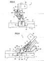
- the guide bar support section 20 extends upwardly from the base section and is pivotally supported to the base section 10 and tiltable laterally as shown in Figs. 6 and 7 .
- the guide bar section 30 is supported to the guide bar holder section 20 and extends in a horizontal and frontward/rearward direction. In the depicted embodiment, the guide bar section 30 is slidable with respect to the guide bar holder section 20.
- a pin 23 extends through the through-hole 12a of the turntable 12 and is movable between frontmost and rearmost positions for regulating the vertical orientation of the holder 22.
- a stop bolt 24 horizontally extends through the holder 22.
- a tip end of the stop bolt 24 is positioned abuttable on an outer peripheral surface of the pin 23 when the pin 23 is positioned at its frontmost position and when the holder 22 is at its vertical position.
- the tip end of the stop bolt 24 is positioned offset from the outer peripheral surface of the pin 23 when the pin 23 is displaced to its rearmost position.
- the holder fixing mechanism 70 is adapted for fixing a laterally tilting angle of the holder 22. Upon fixing the pivot angle of the holder 22, the tilting angle of the circular saw blade 51 is fixed, thereby performing slant cutting.
- the turntable 12 has the rearmost upstanding portion 12A whose upper end portion is configured into an arcuate shape protruding upwardly as shown in Fig. 4 , to form an engagement region 71.
- the holder 22 is provided with a protruding portion 72 including a horizontal section 72A protruding rearwardly from a rear surface 22b of the holder 22 and a vertical section 72B extending downwardly from the horizontal section 72A.
- a part of the engagement region 71 is surrounded by the rear surface 22b of the holder 22 and the protruding portion 72.
- the vertical section 72B has an inward slant wall surface 72a inclined such that a distance between the slant wall surface 72a and the rear surface of the engagement region 71 is gradually increased toward the axis of the holder shaft 21-Further, a slider 73 is movably disposed between the engagement region 71 and the vertical section 728.
- the slider 73 has a rear slant wall surface complementary with the slant wall surface 72a and in sliding contact therewith.
- the horizontal section 72A is formed with a through-hole 72b extending toward the axis of the holder shaft 21.
- the guide bar section 30 generally includes a pair of guide bars 31, 31 and front and back end caps 32A and 32B respectively.
- the guide bars 31 have lengths equal to each other and shorter than a longitudinal length of the turntable 12 (the longitudinal length extends in the frontward/rearward direction).
- the guide bars 31 have a tubular shape and have a circular cross-section whose outer diameter is substantially equal to an inner diameters of the pair of bores 22a, 22a- The guide bars 31 provide sufficient rigidity.
- each guide bar 31 is inserted through each bore 22a.
- each both ends of the guide bar 31 are fixed to the front and back end caps 32A and 32B, respectively.
- the guide bars 31 extend substantially in parallel with the side surface of the circular saw blade 51 as shown in Fig. 2 and substantially in parallel with the upper surface of the base 11 as shown in Fig. 3 .
- the guide bars 31 are arrayed in a vertical plane parallel to the side surface of the circular saw blade 31.
- the above structure of the guide bars 31 can enhance and improve the stiffness of the guide bars 31 against the load applied to the guide bars 31 when the miter saw is carried.
- the outer diameter of the guide bars 31 is slightly greater than the inner diameters of the pair of bores 22a, 22a.
- the saw blade support section 40 is adapted to pivotally movably support the saw blade section 50, and is movable relative to the guide bars 31 between a rearmost position defined by the holder 22 and a frontmost position defined by the front end cap 32A. Further, the saw blade support section 40 can be selectively fixed to the guide bars 31.
- the saw blade support section 40 includes a support segment 41 slidably movable between the holder 22 and the front end cap 32A.
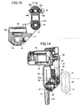
- the saw blade section 50 is movably supported on the support segment 41. More specifically, as shown in Fig- 13, the support segment 41 is formed with an upper bore 41a and a lower bore 41b through which the upper guide bar 31 and the lower guide bar 31 extend, respectively.
- the upper bore 41a is substantially concentric with the upper guide bar 31 and has an inner diameter greater than the outer diameter of the upper guide bar 31.
- the lower bore 41b is substantially concentric with the lower guide bar 31 and has an inner diameter greater than the outer diameter of the lower guide bar 31.
- a ball bearing 42 is disposed in the lower bore 41b.
- the ball bearing 42 has an inner diameter approximately equal to the outer diameter of the lower guide bar 31, and has an outer peripheral surface in sliding contact with the lower bore 41b.
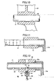
- the lower bore 41b has an axial length approximately equal to an axial length of the ball bearing 42. This axial length is the minimum length for maintaining sufficient sliding performance of the support segment 41 relative to the guide bars 31. It should be noted that the lower guide bar 31 can be supported in the lower bore 41b by an oil-impregnated metal as shown in Fig. 9 instead of the ball bearing 42.
- a saw blade shaft 57 is rotatably supported on the gear case 52.
- the circular saw blade 51 is coaxially mounted on the saw blade shaft 57.
- a safety cover 58 is pivotally supported to the gear case 52 for protectively covering a portion of the circular saw blade 51 projecting out of the saw blade cover 53.
- the safety cover 58 is adapted to cover the projecting out portion of the circular saw blade 51 when the saw blade section 50 is at the upper pivot position shown in Fig. 1 , and to expose the projecting out portion to the atmosphere when the saw blade section 50 is at the lower pivot position shown in Fig. 3 .
- a link mechanism (not shown) is provided for pivotally retracting the safety cover 58 into the saw blade cover 53.
- a motor housing 59 is fixed to the gear case 52.
- the motor housing 59 houses therein the motor 56 which has a motor shaft 60 extending in parallel with the saw blade shaft 57 and supported rotatably on the gear case 52.
- the motor 56 is positioned such that an imaginary plane containing the side surface of the circular saw blade 51 intersects a part of the motor 56.
- a handle 54 is provided integrally with the motor housing 59 (See Fig. 1 ).
- the handle 54 is located on an imaginary plane containing the side surface of the circular saw blade 51.
- a sub-handle 67 as a transfer handle is provided integrally with the motor housing 59 (See Fig. 1 ).
- the sub-handle 67 extends in a direction parallel with the guide bars 31 when the saw blade section 50 is pivotaly moved to its most downward position as shown in Fig. 3 .
- the sub-handle 67 is deviated away from the center line L including the lateral center C, which is aligned with the center of the cutting width of the circular saw blade 51.
- the sub-handle 67 is positioned between the side surface of the circular saw blade 51 and the guide bars 31, when viewed from above.
- the upper and lower guide bars 31, 31 are arrayed in a direction parallel with the side surface of the circular saw blade 51. That is, an imaginary line L1 connecting axes of the upper and lower guide bars 31,31 extends substantially in parallel with the side surface of the circular saw blade 51.
- the guide bars 31 can be slid rearward until the saw blade support section 40 contacts the holder 22, as shown in Fig. 3 .
- the guide bars 31 are protruded from the holder 22 to a large extent. In this case, the cutting operation can be performed without paying considerable attention to the guide bars 31. Therefore, the operability of the miter saw 1 can be improved if a sufficient working area is prepared.
Landscapes
- Engineering & Computer Science (AREA)
- Mechanical Engineering (AREA)
- Life Sciences & Earth Sciences (AREA)
- Wood Science & Technology (AREA)
- Forests & Forestry (AREA)
- Sawing (AREA)
Claims (16)
- Eine Gehrungssäge, bestehend aus:einem Unterteil (10), das eine Oberfläche zur Auflage eines zu sägenden Werkstücks (W) aufweist;einer Halterung (20), die sich auf dem Unterteil (10) befindet;einem Sägeblattteil (50), welches ein Kreissägeblatt (51) zum Sägen des Werkstücks (W) umfasst;einem Sägeblatt-Trägerelement (40), um das Kreissägeblattelement (50) schwenkbar zu tragen; undeinem Führungsschienenteil (30), das eine Führungsschiene (31) beinhaltet;wobei die Führungsschiene (31) verschiebbar von der Halterung (20) gehalten wird und sich im Wesentlichen parallel zur Oberfläche des Unterteils (10) erstreckt, dadurch gekennzeichnet, dass die Gehrungssäge überdies Folgendes beinhaltet:ein erste Einrast-Vorrichtung (45, 80) zum Einrasten der Führungsschiene (31) in die Halterung (20), wobei die erste Einrast-Vorrichtung eine Bewegung der Führungsschiene (21) im Hinblick auf die Halterung (20) einschränkt; undeine zweite Einrast-Vorrichtung (49) zum Einrasten des Sägeblatt-Trägerelements (40) in die Führungsschiene (31), wobei die zweite Einrast-Vorrichtung eine Bewegung des Sägeblatt-Trägerelements (40) entlang der Führungsschiene (31) einschränkt;das Sägeblatt-Trägerelement (40) wird von der Führungsschiene (31) gehalten und ist entlang der Führungsschiebe (31) verschiebbar, wobei die Führungsschiene (31) sich von der Halterung (20) über dem Unterteil (10) vorwärts erstreckt und ein Schieber der Führungsschiene (31) im Hinblick auf die Halterung (20) einen verschiebbaren Anteil des Sägeblatt-Trägerelements (40) entlang der Führungsschiene (31) verändert.
- Die Gehrungssäge, wie in Anspruch 1 beansprucht, worin die erste Einrast-Vorrichtung (80) Folgendes beinhaltet:eine Vielzahl von Bohrungen (81), die in vorher festgelegten Abständen in der Längsrichtung der Führungsschiene (31) positioniert sind, undeinen Stift (82), der selektiv in eine der Vielzahl von Bohrungen (81) eingreifen kann.
- Die Gehrungssäge, wie in Anspruch 1 beansprucht, worin ein Schiebewiderstand der Führungsschiene (31) im Verhältnis zur Halterung (20) größer ist als ein Schiebewiderstand des Sägeblatt-Trägerelements (40) im Verhältnis zur Führungsschiene (31).
- Die Gehrungssäge, wie in Anspruch 1 beansprucht, worin die Führungsschiene (31) kürzer ist als die Länge des Unterteils (10) in der Längsrichtung.
- Die Gehrungssäge, wie in Anspruch 1 beansprucht, worin das Führungsschienenelement (30) eine erste Führungsschiene (31) mit zwei Enden sowie eine zweite Führungsschiene (31) mit zwei Enden umfasst, wobei eines der Enden der ersten Führungsschiene (31) und eines der Enden der zweiten Führungsschiene (31) über ein Verbindungsglied (32A, 32B) miteinander verbunden sind.
- Die Gehrungssäge, wie in Anspruch 1 beansprucht, worin die Halterung (20) eine Durchgangsbohrung (22a) umfasst, durch welche die Führungsschiene (31) geschoben werden kann, sowie ein Kugellager (35), das sich in der Durchgangsbohrung (22a) befindet.
- Die Gehrungssäge, wie in Anspruch 1 beansprucht, worin die Halterung (20) eine Durchgangsbohrung (22a) umfasst, durch welche die Führungsschiene (31) geschoben werden kann, sowie ein ölgetränktes Metall (37), das sich in der Durchgangsbohrung (22a) befindet.
- Die Gehrungssäge, wie in Anspruch 1 beansprucht, worin die Führungsschiene (31) eine Vielzahl von Markierungen aufweist, von denen jede Markierung ein Positionsverhältnis zwischen der Führungsschiene (31) und der Halterung (20) anzeigt.
- Die Gehrungssäge, wie in Anspruch 1 beansprucht, die überdies Anschlagmittel (151) zur Begrenzung einer Drehbewegung des Sägeblattelements (50) nach unten umfasst.
- Die Gehrungssäge, wie in Anspruch 1 beansprucht, überdies bestehend aus:einem Griff (67) zum Tragen der Gehrungssäge, worin das Kreissägeblatt (51) eine Rotationswalze (57) und eine Seitenfläche aufweist und die Gehrungssäge sich in der Breite parallel zur Rotationswalze (57) erstreckt, wobei das Kreissägeblatt (51) in der Nähe einer Mitte der Breite positioniert ist,worin die Führungsschiene (31) von der Seitenfläche durch einen vorher festgelegten Abstand abgelenkt wird, undworin der Griff (67) zwischen dem Kreissägeblatt (51) und der Führungsschiene (31) in der Breitenrichtung positioniert ist.
- Die Gehrungssäge, wie in Anspruch 10 beansprucht, worin der Griff (67) einen Griffteil zum Ergreifen umfasst, wobei der Griffteil in horizontaler Richtung bleibt, wenn das Sägeblattelement (50) in der niedrigsten Stellung positioniert ist.
- Die Gehrungssäge, wie in Anspruch 10 beansprucht, worin der Griff (67) in der Nähe eines Schwerpunkts der Gehrungssäge positioniert ist, wenn das Sägeblattelement (50) entlang der Führungsschiene (31) in die hinterste Stellung geschoben wird.
- Die Gehrungssäge, wie in Anspruch 10 beansprucht, worin das Führungsschienenelement (30) Folgendes umfasst:eine erste Führungsschiene (31) mit einer ersten zentralen Längsachse; undeine zweite Führungsschiene (31) mit einer zweiten zentralen Längsachse, wobei die erste und zweite Führungsschiene (31) eine Ebene, welche die erste und zweite Längsachse einschließt, definiert, worin die Ebene parallel zur Seitenfläche des Kreissägeblatts (51) positioniert ist.
- Die Gehrungssäge, wie in Anspruch 10 beansprucht, worin die Führungsschiene (31) kürzer als die Länge des Unterteils (10) in der Längsrichtung ist.
- Die Gehrungssäge, wie in Anspruch 1 beansprucht, worin die Führungsschiene (31) im Hinblick auf die Halterung (20) verschiebbar ist, um einen Schneidevorgang durchzuführen, wobei das Sägeblatt-Trägerelement (40) in die Führungsschiene (31) einrastet.
- Die Gehrungssäge, wie in Anspruch 1 beansprucht, worin das Sägeblatt-Trägerelement (40) im Hinblick auf die Führungsschiene (31) verschiebbar ist, um einen Schneidevorgang durchzuführen, wobei die Führungsschiene (31) in die Halterung (20) einrastet.
Applications Claiming Priority (2)
| Application Number | Priority Date | Filing Date | Title |
|---|---|---|---|
| JP2004255599A JP4827160B2 (ja) | 2004-09-02 | 2004-09-02 | 卓上切断機 |
| JP2004255494A JP4483488B2 (ja) | 2004-09-02 | 2004-09-02 | 卓上切断機 |
Publications (2)
| Publication Number | Publication Date |
|---|---|
| EP1632324A1 EP1632324A1 (de) | 2006-03-08 |
| EP1632324B1 true EP1632324B1 (de) | 2012-05-30 |
Family
ID=35385481
Family Applications (1)
| Application Number | Title | Priority Date | Filing Date |
|---|---|---|---|
| EP20050255380 Expired - Lifetime EP1632324B1 (de) | 2004-09-02 | 2005-09-02 | Schlittengeführte Gehrungssäge |
Country Status (5)
| Country | Link |
|---|---|
| US (2) | US7997177B2 (de) |
| EP (1) | EP1632324B1 (de) |
| AU (1) | AU2005205796B2 (de) |
| RU (1) | RU2308359C2 (de) |
| TW (1) | TWI303203B (de) |
Families Citing this family (42)
| Publication number | Priority date | Publication date | Assignee | Title |
|---|---|---|---|---|
| EP1632324B1 (de) * | 2004-09-02 | 2012-05-30 | Hitachi Koki Co., Ltd. | Schlittengeführte Gehrungssäge |
| EP1818144B1 (de) * | 2005-04-29 | 2012-09-26 | Black & Decker, Inc. | Gehrungswinkelarretierung für Gehrungssäge |
| US20060243113A1 (en) * | 2005-04-29 | 2006-11-02 | Kaye Thomas R Jr | Bevel lock assembly for miter saws |
| JP2010501361A (ja) * | 2006-08-18 | 2010-01-21 | マニフォールド・プロダクツ・エルエルシー | ソーの調整機構 |
| CN101821066B (zh) * | 2007-10-12 | 2012-05-23 | 利优比株式会社 | 滑动式切割机 |
| GB0723700D0 (en) | 2007-12-04 | 2008-01-16 | Gmca Pty Ltd | Power tool cutting apparatus |
| JP5284055B2 (ja) * | 2007-12-12 | 2013-09-11 | 株式会社マキタ | 卓上切断機 |
| JP5154274B2 (ja) * | 2008-03-21 | 2013-02-27 | 株式会社マキタ | 卓上切断機 |
| JP5064274B2 (ja) * | 2008-03-21 | 2012-10-31 | 株式会社マキタ | 卓上切断機 |
| JP5179232B2 (ja) * | 2008-03-21 | 2013-04-10 | 株式会社マキタ | 卓上切断機 |
| WO2009130938A1 (ja) * | 2008-04-21 | 2009-10-29 | 株式会社 マキタ | 卓上丸鋸盤用治具及び卓上丸鋸盤 |
| JP5128361B2 (ja) * | 2008-04-30 | 2013-01-23 | 株式会社マキタ | バイス装置及び卓上丸鋸盤 |
| CN101612674A (zh) * | 2008-06-23 | 2009-12-30 | 苏州宝时得电动工具有限公司 | 斜断锯 |
| JP5231112B2 (ja) | 2008-07-14 | 2013-07-10 | 株式会社マキタ | 卓上切断機 |
| JP5249705B2 (ja) * | 2008-10-10 | 2013-07-31 | 株式会社マキタ | 卓上切断機 |
| JP5666094B2 (ja) * | 2009-01-30 | 2015-02-12 | 株式会社マキタ | 卓上切断機 |
| DE202010000260U1 (de) * | 2010-02-26 | 2010-06-02 | Freund Maschinenfabrik Gmbh & Co. Kg | Ständer-Kreismesser |
| JP5468420B2 (ja) * | 2010-03-04 | 2014-04-09 | 株式会社マキタ | 手持ち式切断工具 |
| CN201824014U (zh) * | 2010-06-28 | 2011-05-11 | 南京德朔实业有限公司 | 斜切锯 |
| CN201841314U (zh) * | 2010-08-03 | 2011-05-25 | 南京德朔实业有限公司 | 斜切锯的拉杆锁定装置 |
| US8931386B2 (en) | 2010-12-23 | 2015-01-13 | Robert Bosch Gmbh | Miter saw with bevel lock |
| CN102756170B (zh) * | 2011-04-29 | 2015-03-11 | 苏州宝时得电动工具有限公司 | 斜断锯 |
| UA99558C2 (uk) * | 2011-07-01 | 2012-08-27 | Михаил Геннадьевич Белов | Пристрій бєлова для абразивно-лазерного різання |
| US9649703B2 (en) | 2012-03-15 | 2017-05-16 | Rexon Industrial Corp., Ltd. | Circular saw with a moving mechanism |
| CA2861991C (en) * | 2012-07-04 | 2016-05-24 | Sumec Hardware & Tools Co., Ltd. | Power miter saw |
| GB2504275A (en) * | 2012-07-23 | 2014-01-29 | Black & Decker Inc | Compact Drive Mechanism for Sliding Compound Mitre Saw |
| US9283628B2 (en) * | 2013-03-08 | 2016-03-15 | Black & Decker Inc. | Chop saw with improved storage mode |
| JP2015123543A (ja) * | 2013-12-26 | 2015-07-06 | 株式会社マキタ | 卓上切断工具 |
| JP6274602B2 (ja) * | 2014-02-28 | 2018-02-07 | 日立工機株式会社 | 卓上切断機 |
| US10882123B2 (en) | 2015-02-25 | 2021-01-05 | Milwaukee Electric Tool Corporation | Miter saw |
| CN105171103B (zh) * | 2015-09-18 | 2017-10-27 | 苏州国量量具科技有限公司 | 滚动式切割装置 |
| CN110023018A (zh) * | 2016-11-30 | 2019-07-16 | 工机控股株式会社 | 动力工具 |
| US10898960B2 (en) | 2018-03-28 | 2021-01-26 | Black & Decker Inc. | Miter saw |
| CN113182600B (zh) * | 2020-01-14 | 2023-09-12 | 苏州宝时得电动工具有限公司 | 斜断锯以及工件切割方法、工件定位方法 |
| CN111168782B (zh) * | 2020-01-21 | 2024-11-12 | 南京海威机械有限公司 | 用于制造广泛的切口的方法和设备 |
| US12186817B2 (en) | 2020-12-02 | 2025-01-07 | Makita Corporation | Sliding cutting machine |
| US11628587B2 (en) | 2021-02-24 | 2023-04-18 | Techtronic Cordless Gp | Floor saw with blade guard |
| CN114042998A (zh) * | 2021-11-11 | 2022-02-15 | 陕西飞机工业有限责任公司 | 航空直导管端面数控成形机及数控成形方法 |
| JP7770934B2 (ja) * | 2022-01-12 | 2025-11-17 | 株式会社マキタ | 卓上切断機 |
| GB2619777A (en) * | 2022-06-17 | 2023-12-20 | Evolution Power Tools Ltd | An improved chop saw |
| CN116214637B (zh) * | 2023-03-27 | 2024-11-26 | 金华市亚虎工具有限公司 | 具有导向切割功能的斜断锯支架及其切割方法 |
| TWI872531B (zh) * | 2023-05-05 | 2025-02-11 | 力山工業股份有限公司 | 具有集屑組件的鋸切機 |
Family Cites Families (39)
| Publication number | Priority date | Publication date | Assignee | Title |
|---|---|---|---|---|
| US1852387A (en) * | 1930-02-08 | 1932-04-05 | Wieden Louis | Woodworking machine |
| US2241888A (en) | 1939-02-15 | 1941-05-13 | Bertha L Macgregor | Vehicle light |
| US3302669A (en) * | 1964-06-29 | 1967-02-07 | Edler Adolph | Motor powered radial arm tool support |
| US4036093A (en) * | 1976-08-18 | 1977-07-19 | Excor, Inc. | Saw for cutting truss members, rafters and the like with dimensional accuracy |
| SU965641A1 (ru) * | 1980-11-10 | 1982-10-15 | Минское специальное конструкторское бюро протяжных станков | Отрезной станок с измен емым углом отрезки |
| USD287694S (en) * | 1984-01-26 | 1987-01-13 | Ryobi Limited | Mitre saw |
| JPS6211526A (ja) | 1985-07-08 | 1987-01-20 | Sumitomo Metal Mining Co Ltd | 充填層集塵装置 |
| JPH0612164B2 (ja) | 1985-08-15 | 1994-02-16 | 三菱重工業株式会社 | 吊下げ形ボイラの火炉改造方法 |
| JPS62200401A (ja) | 1986-02-28 | 1987-09-04 | Japan Tobacco Inc | プロセスコミユニケ−タおよびプロセスコミユニケ−シヨン方法 |
| JPH0518082Y2 (de) * | 1987-02-20 | 1993-05-14 | ||
| USD306031S (en) * | 1988-01-11 | 1990-02-13 | Hitachi Koki Haramachi Co., Ltd. | Mitre saw |
| JPH0395812U (de) * | 1990-01-23 | 1991-09-30 | ||
| US5241888A (en) * | 1992-07-31 | 1993-09-07 | Rexon Industrial Corporation, Ltd. | Slidable compound miter saw |
| JP2537141B2 (ja) | 1994-06-23 | 1996-09-25 | 株式会社マキタ | 卓上丸鋸盤 |
| USD374803S (en) * | 1995-06-09 | 1996-10-22 | Emerson Electric Co. | Compound miter saw |
| GB2304075B (en) | 1995-08-10 | 1999-10-20 | Milwaukee Electric Tool Corp | Indexing override mechanism for a slide compound miter saw |
| GB2304076B (en) | 1995-08-10 | 1999-08-25 | Milwaukee Electric Tool Corp | Support assembly for a slide compound miter saw |
| US5937720A (en) | 1995-08-10 | 1999-08-17 | Milwaukee Electric Tool Corporation | Lower blade guard actuating mechanism for a slide compound miter saw |
| US5819624A (en) | 1996-07-30 | 1998-10-13 | Milwaukee Electric Tool Corporation | Indexing override mechanism for a slide compound miter saw |
| US5862732A (en) | 1996-07-30 | 1999-01-26 | Milwaukee Electric Tool Corporation | Support assembly for a slide compound miter saw |
| US5907987A (en) * | 1996-12-05 | 1999-06-01 | Stumpf; William R. | Bevel locking system for a sliding compound miter saw |
| USD389494S (en) * | 1996-11-04 | 1998-01-20 | Rexon Industrial Corp., Ltd. | Miter saw |
| JP3490259B2 (ja) | 1997-07-22 | 2004-01-26 | 株式会社マキタ | 丸鋸盤 |
| JPH11170202A (ja) | 1997-12-12 | 1999-06-29 | Hitachi Koki Co Ltd | スライド式卓上切断機 |
| JP3490275B2 (ja) | 1998-01-12 | 2004-01-26 | 株式会社マキタ | スライドマルノコ |
| CN1191907C (zh) * | 1998-03-11 | 2005-03-09 | 布莱克和戴克公司 | 锯器 |
| USD424072S (en) * | 1999-03-03 | 2000-05-02 | Makita Corporation | Miter saw |
| US6918330B2 (en) * | 2000-10-24 | 2005-07-19 | Thomson Industries, Inc. | Adjustable tool station |
| US6550363B2 (en) * | 2001-04-10 | 2003-04-22 | Cai Bai He | Extendible compound miter saw |
| CA2372451A1 (en) | 2002-02-19 | 2003-08-19 | Gerald John Williams | Compact sliding compound mitre saw |
| JP4209120B2 (ja) | 2002-02-22 | 2009-01-14 | 株式会社マキタ | 切断機 |
| USD487754S1 (en) * | 2002-09-26 | 2004-03-23 | P & F Brother Industrial Corporation | Sliding compound miter saw |
| US20050098010A1 (en) * | 2003-07-30 | 2005-05-12 | Ning Bo Yang Ming Electric Tools Company, Ltd. | Electric miter saw |
| JP4254429B2 (ja) | 2003-08-28 | 2009-04-15 | 日立工機株式会社 | 卓上スライド切断機 |
| US6901834B2 (en) * | 2003-09-26 | 2005-06-07 | Chin-Chin Chang | Movement adjust device for a circular saw |
| DE202004004929U1 (de) * | 2004-03-26 | 2004-06-09 | Lutz Gmbh Maschinenbau | Kapp- oder Gehrungssäge mit Gleitführung |
| EP1632324B1 (de) * | 2004-09-02 | 2012-05-30 | Hitachi Koki Co., Ltd. | Schlittengeführte Gehrungssäge |
| USD529936S1 (en) * | 2005-02-28 | 2006-10-10 | Hitachi Koki Co., Ltd. | Slide compound miter saw |
| AU312403S (en) * | 2005-08-01 | 2007-01-16 | Black & Decker Inc | A saw |
-
2005
- 2005-09-02 EP EP20050255380 patent/EP1632324B1/de not_active Expired - Lifetime
- 2005-09-02 US US11/217,300 patent/US7997177B2/en not_active Expired - Lifetime
- 2005-09-02 RU RU2005128240A patent/RU2308359C2/ru not_active IP Right Cessation
- 2005-09-02 AU AU2005205796A patent/AU2005205796B2/en not_active Ceased
- 2005-09-02 TW TW94130086A patent/TWI303203B/zh not_active IP Right Cessation
-
2011
- 2011-08-11 US US13/207,730 patent/US8561513B2/en not_active Expired - Fee Related
Also Published As
| Publication number | Publication date |
|---|---|
| TWI303203B (en) | 2008-11-21 |
| RU2308359C2 (ru) | 2007-10-20 |
| US20060042442A1 (en) | 2006-03-02 |
| RU2005128240A (ru) | 2007-03-10 |
| US8561513B2 (en) | 2013-10-22 |
| AU2005205796A1 (en) | 2006-03-16 |
| US20110290092A1 (en) | 2011-12-01 |
| EP1632324A1 (de) | 2006-03-08 |
| TW200618973A (en) | 2006-06-16 |
| AU2005205796B2 (en) | 2007-08-09 |
| US7997177B2 (en) | 2011-08-16 |
Similar Documents
| Publication | Publication Date | Title |
|---|---|---|
| US7997177B2 (en) | Miter saw | |
| EP1579938B1 (de) | Kapp-oder Gehrungssäge der aufwärts und abwärts schwenkbar und nach rechts und links neigbar ist | |
| US7726225B2 (en) | Miter saw having holder fixing mechanism | |
| US6971298B2 (en) | Miter saw with laterally tiltable circular saw blade | |
| US8181559B1 (en) | Rolling plate assembly attachment for portable power cutting tools including an improved structural design and manufactured out of improved materials, an improved wheel configuration, and an adjustable bevel gear and a cutting guide | |
| JP3888165B2 (ja) | 携帯用切断機 | |
| US8209872B1 (en) | Rolling plate assembly attachment for portable power cutting tools including an improved structural design and manufactured out of improved materials, an improved wheel configuration, and an adjustable bevel gear and a cutting guide | |
| EP2078575B1 (de) | Schneidevorrichtung | |
| US8025001B2 (en) | Miter saw with support devices | |
| US20100212467A1 (en) | Slide-type cutting machine | |
| US8424433B2 (en) | Support leg devices and cutting tools having the support leg devices | |
| EP1510307B1 (de) | Schlittengeführte Gehrungssäge | |
| US7631585B2 (en) | Kickback-inhibiting devices for cutting devices | |
| US7444913B2 (en) | Parallel fences | |
| EP2248642A1 (de) | Vorrichtung für eine tischkreissäge und tischkreissäge | |
| CN100448581C (zh) | 斜切锯 | |
| JP2006069057A (ja) | 卓上切断機 | |
| JP5105210B2 (ja) | 卓上切断機 | |
| JP5082635B2 (ja) | 卓上切断機 | |
| JP5101232B2 (ja) | スライド式切断機 | |
| JP2024141955A (ja) | 携帯用加工機 | |
| JP5001118B2 (ja) | スライド式切断機 | |
| JP2012210695A (ja) | スライド式卓上切断機 | |
| JP2016221624A (ja) | 卓上切断機 |
Legal Events
| Date | Code | Title | Description |
|---|---|---|---|
| PUAI | Public reference made under article 153(3) epc to a published international application that has entered the european phase |
Free format text: ORIGINAL CODE: 0009012 |
|
| AK | Designated contracting states |
Kind code of ref document: A1 Designated state(s): AT BE BG CH CY CZ DE DK EE ES FI FR GB GR HU IE IS IT LI LT LU LV MC NL PL PT RO SE SI SK TR |
|
| AX | Request for extension of the european patent |
Extension state: AL BA HR MK YU |
|
| 17P | Request for examination filed |
Effective date: 20060904 |
|
| 17Q | First examination report despatched |
Effective date: 20061012 |
|
| AKX | Designation fees paid |
Designated state(s): AT BE BG CH CY CZ DE DK EE ES FI FR GB GR HU IE IS IT LI LT LU LV MC NL PL PT RO SE SI SK TR |
|
| GRAP | Despatch of communication of intention to grant a patent |
Free format text: ORIGINAL CODE: EPIDOSNIGR1 |
|
| GRAS | Grant fee paid |
Free format text: ORIGINAL CODE: EPIDOSNIGR3 |
|
| GRAA | (expected) grant |
Free format text: ORIGINAL CODE: 0009210 |
|
| AK | Designated contracting states |
Kind code of ref document: B1 Designated state(s): AT BE BG CH CY CZ DE DK EE ES FI FR GB GR HU IE IS IT LI LT LU LV MC NL PL PT RO SE SI SK TR |
|
| REG | Reference to a national code |
Ref country code: GB Ref legal event code: FG4D |
|
| REG | Reference to a national code |
Ref country code: CH Ref legal event code: EP |
|
| REG | Reference to a national code |
Ref country code: DE Ref legal event code: R081 Ref document number: 602005034394 Country of ref document: DE Owner name: KOKI HOLDINGS CO., LTD., JP Free format text: FORMER OWNER: HITACHI KOKI CO., LTD., TOKIO/TOKYO, JP |
|
| REG | Reference to a national code |
Ref country code: AT Ref legal event code: REF Ref document number: 559848 Country of ref document: AT Kind code of ref document: T Effective date: 20120615 |
|
| REG | Reference to a national code |
Ref country code: IE Ref legal event code: FG4D |
|
| REG | Reference to a national code |
Ref country code: DE Ref legal event code: R096 Ref document number: 602005034394 Country of ref document: DE Effective date: 20120802 |
|
| REG | Reference to a national code |
Ref country code: NL Ref legal event code: VDEP Effective date: 20120530 |
|
| REG | Reference to a national code |
Ref country code: LT Ref legal event code: MG4D Effective date: 20120530 |
|
| PG25 | Lapsed in a contracting state [announced via postgrant information from national office to epo] |
Ref country code: SE Free format text: LAPSE BECAUSE OF FAILURE TO SUBMIT A TRANSLATION OF THE DESCRIPTION OR TO PAY THE FEE WITHIN THE PRESCRIBED TIME-LIMIT Effective date: 20120530 Ref country code: CY Free format text: LAPSE BECAUSE OF FAILURE TO SUBMIT A TRANSLATION OF THE DESCRIPTION OR TO PAY THE FEE WITHIN THE PRESCRIBED TIME-LIMIT Effective date: 20120530 Ref country code: IS Free format text: LAPSE BECAUSE OF FAILURE TO SUBMIT A TRANSLATION OF THE DESCRIPTION OR TO PAY THE FEE WITHIN THE PRESCRIBED TIME-LIMIT Effective date: 20120930 Ref country code: LT Free format text: LAPSE BECAUSE OF FAILURE TO SUBMIT A TRANSLATION OF THE DESCRIPTION OR TO PAY THE FEE WITHIN THE PRESCRIBED TIME-LIMIT Effective date: 20120530 Ref country code: FI Free format text: LAPSE BECAUSE OF FAILURE TO SUBMIT A TRANSLATION OF THE DESCRIPTION OR TO PAY THE FEE WITHIN THE PRESCRIBED TIME-LIMIT Effective date: 20120530 |
|
| REG | Reference to a national code |
Ref country code: AT Ref legal event code: MK05 Ref document number: 559848 Country of ref document: AT Kind code of ref document: T Effective date: 20120530 |
|
| PG25 | Lapsed in a contracting state [announced via postgrant information from national office to epo] |
Ref country code: LV Free format text: LAPSE BECAUSE OF FAILURE TO SUBMIT A TRANSLATION OF THE DESCRIPTION OR TO PAY THE FEE WITHIN THE PRESCRIBED TIME-LIMIT Effective date: 20120530 Ref country code: GR Free format text: LAPSE BECAUSE OF FAILURE TO SUBMIT A TRANSLATION OF THE DESCRIPTION OR TO PAY THE FEE WITHIN THE PRESCRIBED TIME-LIMIT Effective date: 20120831 Ref country code: SI Free format text: LAPSE BECAUSE OF FAILURE TO SUBMIT A TRANSLATION OF THE DESCRIPTION OR TO PAY THE FEE WITHIN THE PRESCRIBED TIME-LIMIT Effective date: 20120530 |
|
| PG25 | Lapsed in a contracting state [announced via postgrant information from national office to epo] |
Ref country code: BE Free format text: LAPSE BECAUSE OF FAILURE TO SUBMIT A TRANSLATION OF THE DESCRIPTION OR TO PAY THE FEE WITHIN THE PRESCRIBED TIME-LIMIT Effective date: 20120530 |
|
| PG25 | Lapsed in a contracting state [announced via postgrant information from national office to epo] |
Ref country code: EE Free format text: LAPSE BECAUSE OF FAILURE TO SUBMIT A TRANSLATION OF THE DESCRIPTION OR TO PAY THE FEE WITHIN THE PRESCRIBED TIME-LIMIT Effective date: 20120530 Ref country code: SK Free format text: LAPSE BECAUSE OF FAILURE TO SUBMIT A TRANSLATION OF THE DESCRIPTION OR TO PAY THE FEE WITHIN THE PRESCRIBED TIME-LIMIT Effective date: 20120530 Ref country code: CZ Free format text: LAPSE BECAUSE OF FAILURE TO SUBMIT A TRANSLATION OF THE DESCRIPTION OR TO PAY THE FEE WITHIN THE PRESCRIBED TIME-LIMIT Effective date: 20120530 Ref country code: DK Free format text: LAPSE BECAUSE OF FAILURE TO SUBMIT A TRANSLATION OF THE DESCRIPTION OR TO PAY THE FEE WITHIN THE PRESCRIBED TIME-LIMIT Effective date: 20120530 Ref country code: RO Free format text: LAPSE BECAUSE OF FAILURE TO SUBMIT A TRANSLATION OF THE DESCRIPTION OR TO PAY THE FEE WITHIN THE PRESCRIBED TIME-LIMIT Effective date: 20120530 Ref country code: AT Free format text: LAPSE BECAUSE OF FAILURE TO SUBMIT A TRANSLATION OF THE DESCRIPTION OR TO PAY THE FEE WITHIN THE PRESCRIBED TIME-LIMIT Effective date: 20120530 Ref country code: NL Free format text: LAPSE BECAUSE OF FAILURE TO SUBMIT A TRANSLATION OF THE DESCRIPTION OR TO PAY THE FEE WITHIN THE PRESCRIBED TIME-LIMIT Effective date: 20120530 |
|
| PG25 | Lapsed in a contracting state [announced via postgrant information from national office to epo] |
Ref country code: IT Free format text: LAPSE BECAUSE OF FAILURE TO SUBMIT A TRANSLATION OF THE DESCRIPTION OR TO PAY THE FEE WITHIN THE PRESCRIBED TIME-LIMIT Effective date: 20120530 Ref country code: PT Free format text: LAPSE BECAUSE OF FAILURE TO SUBMIT A TRANSLATION OF THE DESCRIPTION OR TO PAY THE FEE WITHIN THE PRESCRIBED TIME-LIMIT Effective date: 20121001 Ref country code: PL Free format text: LAPSE BECAUSE OF FAILURE TO SUBMIT A TRANSLATION OF THE DESCRIPTION OR TO PAY THE FEE WITHIN THE PRESCRIBED TIME-LIMIT Effective date: 20120530 |
|
| PLBE | No opposition filed within time limit |
Free format text: ORIGINAL CODE: 0009261 |
|
| STAA | Information on the status of an ep patent application or granted ep patent |
Free format text: STATUS: NO OPPOSITION FILED WITHIN TIME LIMIT |
|
| PG25 | Lapsed in a contracting state [announced via postgrant information from national office to epo] |
Ref country code: MC Free format text: LAPSE BECAUSE OF NON-PAYMENT OF DUE FEES Effective date: 20120930 Ref country code: ES Free format text: LAPSE BECAUSE OF FAILURE TO SUBMIT A TRANSLATION OF THE DESCRIPTION OR TO PAY THE FEE WITHIN THE PRESCRIBED TIME-LIMIT Effective date: 20120910 |
|
| REG | Reference to a national code |
Ref country code: CH Ref legal event code: PL |
|
| 26N | No opposition filed |
Effective date: 20130301 |
|
| REG | Reference to a national code |
Ref country code: IE Ref legal event code: MM4A |
|
| REG | Reference to a national code |
Ref country code: DE Ref legal event code: R097 Ref document number: 602005034394 Country of ref document: DE Effective date: 20130301 |
|
| PG25 | Lapsed in a contracting state [announced via postgrant information from national office to epo] |
Ref country code: IE Free format text: LAPSE BECAUSE OF NON-PAYMENT OF DUE FEES Effective date: 20120902 Ref country code: BG Free format text: LAPSE BECAUSE OF FAILURE TO SUBMIT A TRANSLATION OF THE DESCRIPTION OR TO PAY THE FEE WITHIN THE PRESCRIBED TIME-LIMIT Effective date: 20120830 Ref country code: LI Free format text: LAPSE BECAUSE OF NON-PAYMENT OF DUE FEES Effective date: 20120930 Ref country code: CH Free format text: LAPSE BECAUSE OF NON-PAYMENT OF DUE FEES Effective date: 20120930 |
|
| PG25 | Lapsed in a contracting state [announced via postgrant information from national office to epo] |
Ref country code: TR Free format text: LAPSE BECAUSE OF FAILURE TO SUBMIT A TRANSLATION OF THE DESCRIPTION OR TO PAY THE FEE WITHIN THE PRESCRIBED TIME-LIMIT Effective date: 20120530 |
|
| PG25 | Lapsed in a contracting state [announced via postgrant information from national office to epo] |
Ref country code: LU Free format text: LAPSE BECAUSE OF NON-PAYMENT OF DUE FEES Effective date: 20120902 |
|
| PG25 | Lapsed in a contracting state [announced via postgrant information from national office to epo] |
Ref country code: HU Free format text: LAPSE BECAUSE OF FAILURE TO SUBMIT A TRANSLATION OF THE DESCRIPTION OR TO PAY THE FEE WITHIN THE PRESCRIBED TIME-LIMIT Effective date: 20050902 |
|
| REG | Reference to a national code |
Ref country code: DE Ref legal event code: R082 Ref document number: 602005034394 Country of ref document: DE Representative=s name: WEICKMANN & WEICKMANN PATENTANWAELTE - RECHTSA, DE Ref country code: DE Ref legal event code: R082 Ref document number: 602005034394 Country of ref document: DE Representative=s name: WEICKMANN & WEICKMANN PATENT- UND RECHTSANWAEL, DE |
|
| REG | Reference to a national code |
Ref country code: FR Ref legal event code: PLFP Year of fee payment: 12 |
|
| REG | Reference to a national code |
Ref country code: FR Ref legal event code: PLFP Year of fee payment: 13 |
|
| REG | Reference to a national code |
Ref country code: DE Ref legal event code: R082 Ref document number: 602005034394 Country of ref document: DE Representative=s name: WEICKMANN & WEICKMANN PATENT- UND RECHTSANWAEL, DE Ref country code: DE Ref legal event code: R081 Ref document number: 602005034394 Country of ref document: DE Owner name: KOKI HOLDINGS CO., LTD., JP Free format text: FORMER OWNER: HITACHI KOKI CO., LTD., TOKIO/TOKYO, JP |
|
| REG | Reference to a national code |
Ref country code: DE Ref legal event code: R084 Ref document number: 602005034394 Country of ref document: DE |
|
| REG | Reference to a national code |
Ref country code: FR Ref legal event code: PLFP Year of fee payment: 14 |
|
| REG | Reference to a national code |
Ref country code: GB Ref legal event code: 746 Effective date: 20181031 |
|
| PGFP | Annual fee paid to national office [announced via postgrant information from national office to epo] |
Ref country code: GB Payment date: 20220920 Year of fee payment: 18 Ref country code: DE Payment date: 20220920 Year of fee payment: 18 |
|
| PGFP | Annual fee paid to national office [announced via postgrant information from national office to epo] |
Ref country code: FR Payment date: 20220922 Year of fee payment: 18 |
|
| REG | Reference to a national code |
Ref country code: DE Ref legal event code: R119 Ref document number: 602005034394 Country of ref document: DE |
|
| GBPC | Gb: european patent ceased through non-payment of renewal fee |
Effective date: 20230902 |
|
| PG25 | Lapsed in a contracting state [announced via postgrant information from national office to epo] |
Ref country code: GB Free format text: LAPSE BECAUSE OF NON-PAYMENT OF DUE FEES Effective date: 20230902 |
|
| PG25 | Lapsed in a contracting state [announced via postgrant information from national office to epo] |
Ref country code: GB Free format text: LAPSE BECAUSE OF NON-PAYMENT OF DUE FEES Effective date: 20230902 Ref country code: FR Free format text: LAPSE BECAUSE OF NON-PAYMENT OF DUE FEES Effective date: 20230930 Ref country code: DE Free format text: LAPSE BECAUSE OF NON-PAYMENT OF DUE FEES Effective date: 20240403 |