EP1632275B1 - Kinderspielfahrzeug - Google Patents
Kinderspielfahrzeug Download PDFInfo
- Publication number
- EP1632275B1 EP1632275B1 EP04030406A EP04030406A EP1632275B1 EP 1632275 B1 EP1632275 B1 EP 1632275B1 EP 04030406 A EP04030406 A EP 04030406A EP 04030406 A EP04030406 A EP 04030406A EP 1632275 B1 EP1632275 B1 EP 1632275B1
- Authority
- EP
- European Patent Office
- Prior art keywords
- support leg
- toy vehicle
- safety
- seat bracket
- safety hook
- Prior art date
- Legal status (The legal status is an assumption and is not a legal conclusion. Google has not performed a legal analysis and makes no representation as to the accuracy of the status listed.)
- Active
Links
- 230000005484 gravity Effects 0.000 claims description 2
- 230000008878 coupling Effects 0.000 description 4
- 238000010168 coupling process Methods 0.000 description 4
- 238000005859 coupling reaction Methods 0.000 description 4
Images


Classifications
-
- A—HUMAN NECESSITIES
- A63—SPORTS; GAMES; AMUSEMENTS
- A63H—TOYS, e.g. TOPS, DOLLS, HOOPS OR BUILDING BLOCKS
- A63H17/00—Toy vehicles, e.g. with self-drive; ; Cranes, winches or the like; Accessories therefor
- A63H17/12—Toy vehicles, e.g. with self-drive; ; Cranes, winches or the like; Accessories therefor with cranes, winches or the like
-
- Y—GENERAL TAGGING OF NEW TECHNOLOGICAL DEVELOPMENTS; GENERAL TAGGING OF CROSS-SECTIONAL TECHNOLOGIES SPANNING OVER SEVERAL SECTIONS OF THE IPC; TECHNICAL SUBJECTS COVERED BY FORMER USPC CROSS-REFERENCE ART COLLECTIONS [XRACs] AND DIGESTS
- Y10—TECHNICAL SUBJECTS COVERED BY FORMER USPC
- Y10S—TECHNICAL SUBJECTS COVERED BY FORMER USPC CROSS-REFERENCE ART COLLECTIONS [XRACs] AND DIGESTS
- Y10S414/00—Material or article handling
- Y10S414/128—Handler-type toys
Definitions
- the invention relates to a toy vehicle, in particular a child pedal vehicle, which preferably has the form of a tractor, without the invention being limited thereto.
- the invention is also applicable to a motorized toy vehicle.
- the toy vehicles with backhoe are e.g. from US-A-3205612, US 2003/160406 or US-A-3176862.
- the present invention has for its object to develop a vehicle of the type considered so that the play value of the vehicle is increased.
- the vehicle should also be operated by small children and meet high safety requirements.
- the invention provides that on the toy vehicle, a backhoe is attached, which is fastened by means of a receiving block to the rear of the vehicle body.
- the receiving block preferably contains a coupling pin, which passes through annular coupling elements of the vehicle body.
- a seat boom is rotatably mounted, which consists of a boom and a seat pan mounted thereon.
- a bucket holding preferably made of plastic existing linkage, which is preferably provided for lifting, lowering and pivoting the bucket with two handles.
- a support leg is attached to the receiving block, which is pivotable between a raised, preferably laterally swung-out position and a lowered position in which the support leg rests with one foot on the floor.
- a securing hook device is mounted, which locks the support leg in the raised position and at the same time the seat boom in a predetermined angular position in a first position, and blocked in a second position, the support leg in the lowered position, wherein also the seat arm for rotation is released.
- the support leg when a child is traveling with the toy vehicle, the support leg must be in the raised position, otherwise the support leg would drag across the floor.
- the support leg in the raised position of the safety hook of the safety hook device is brought into such a position in which the hook engages over the support leg, so that it is held immobile.
- the seat arm is locked in a predetermined angular position, which prevents the seat boom with the linkage thereon and the bucket while driving the toy vehicle can swing back and forth.
- the child When the child wants to use the backhoe, it first moves the safety hook to a preferably slightly raised position in which the support leg is released from the safety hook and is movable to the lowered position in which the support leg rests on the floor. If this is the case, the safety hook is moved to a second, preferably downwardly pivoted position in which the support leg is blocked and at the same time the seat arm is released for rotation. It is preferably provided that the safety hook is rotatably arranged, that is rotated in the different position.
- the receiving block is supported with the backhoe by the support leg on the ground, the child can now safely put on the preferred provided seat shell of the seat cant without the toy vehicle can tilt about the rear axle and without the forces acting on the receiving block damage the toy vehicle can. Since the seat boom is released for rotation, now the backhoe can be pivoted within the intended range of rotation.
- the safety hook device comprises a securing hook, which is rotatable about an axis, a driver, which is rotatably connected to the safety hook, and a securing bolt, which is arranged in the receiving block.
- the securing bolt is slidably disposed in the receiving block, between an upper position in which it engages with its upper end in a recess in the underside of the seat post, and a lower position in which it is lowered at its lower end into a recess Support leg engages.
- the fixedly connected to the axis of rotation driver has a transverse to the axis rod-shaped driving portion which engages in a space between two lateral stops of the securing bolt, so that the securing bolt is displaceable by turning the securing hook and the associated driver up or down ,
- the support leg When the support leg is in the raised position, its position can be secured by the fact that the securing hook on the side remote from its axis with its hook-shaped projection engages behind the support leg.
- the safety hook In order to pivot the support leg in the lowered support position, the safety hook is a little upwards pivoted without run up with his driver on the safety pin, since the driver has a corresponding clearance between the two stops of the locking bolt.
- the safety hook is only turned up so far that the support leg can be swung out.
- the support leg preferably contains two support leg sections extending at an angle to one another and, with its end facing away from the support leg, can be pivoted about an axis lying obliquely to the vertical. The angle is preferably about 45 °.
- the safety hook is pivoted down to a stop, wherein the securing bolt is displaced and with its lower end in a lateral recess enters the support foot, whereby its position is secured.
- the upper end of the securing bolt has emerged from the recess of the seat arm, so that it is freely rotatable.
- the boom supporting the blade is attached to the seat arm, with which the blade can be moved to the desired position and angular position.
- the linkage includes an excavator arm hinged at one end to the seat boom and hinged to the other end of a vane arm with a hinged vane, the excavator arm being pivotable back to a raised end position in which the excavator arm is releasably securable.
- a second securing hook is pivotally mounted on the excavator, which engages behind a mounted on the seat arm stop due to gravity in the swung-back end position of the excavator.
- the second safety hook is in order a horizontal axis rotatable. By pivoting the second safety hook the excavator arm is released.
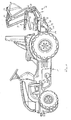
- FIG. 1 shows, at the rear of a pedal-driven children's game gate 1 a designated generally by the reference numeral 2 backhoe is firmly attached.
- a receiving block 3 is fixed by means of a coupling pin 4 ( Figure 5) to the vehicle body 1, wherein the pin 4 passes through coupling rings on the vehicle body 1.
- a seat post 4 is rotatably mounted, which is provided with a seat 5, below which is the hinge.
- an excavator 6 is hinged, to which a rigidly mounted handle 7 and a hinged handle 8 are mounted side by side.
- the pivoting handle 8 is in his middle region hingedly connected to a parallel rod 9, at the free end of a blade 10 is articulated, which is articulated at such a location also at the free end of the excavator 6, that the parallel bar 9 extends parallel to the excavator 6.
- the blade arm 10 is pivotally connected at its free end with a bucket 11, which is also connected via a shear linkage 12 articulated to the excavator 6.
- a support leg 13 is also articulated with a lower support leg 14.
- the support leg 13 is located in the illustration of Figure 1 in a laterally pivoted out of the receiving block 3, raised state, which is secured by a first securing hook 15 which is rotatable about an axis 16.
- the safety hook 15 engages in the state shown with its hook-shaped projection facing away from the axis 16 back of the upper, angled portion of the support leg 13th
- Figure 1 also reveals a second securing hook 17 which engages in the illustrated raised end position of the backhoe integrally formed on the seat arm 4 projection 18 so that the excavator 6 is releasably fixed in the position shown.
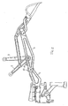
- FIG. 2 shows a state of the backhoe, in which the excavator 6 is released.
- the second securing hook 17 had previously been brought by lifting out of engagement with the integrally formed on the front end of the seat post 4 projection 18, so that the excavator was pivoted forward.
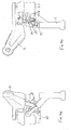
- Figures 3 and 4 show that the support leg 13 consists of an upper support leg portion 19 and a lower support leg portion 20, and that the upper support leg portion 19 about an axis lying obliquely to the vertical axis 21 is pivotable.
- the safety hook 15 is rotatable with a connected to him driver 22 (Figure 5), which has a perpendicular to the plane of Figure 5 rod-shaped driving lug, connected to a securing bolt 23 by the driver lug 24 engages in an elongated recess 25 of the securing bolt 23 between two stops 26 and 27 whose distance is greater than the width of the driving lug 24.
- Figure 3 shows the state in which the support leg 13 is pivoted in the vertical support position.
- the safety pin 23 is still in the upwardly shifted position in which it engages with its upper end in a recess 28 of an integrally formed on the underside of the seat post 4 pivot, so that the seat post 4 is blocked in the associated angular position.
Applications Claiming Priority (1)
| Application Number | Priority Date | Filing Date | Title |
|---|---|---|---|
| DE102004042646A DE102004042646B3 (de) | 2004-09-03 | 2004-09-03 | Kinderspielfahrzeug |
Publications (2)
| Publication Number | Publication Date |
|---|---|
| EP1632275A1 EP1632275A1 (de) | 2006-03-08 |
| EP1632275B1 true EP1632275B1 (de) | 2007-06-06 |
Family
ID=35295582
Family Applications (1)
| Application Number | Title | Priority Date | Filing Date |
|---|---|---|---|
| EP04030406A Active EP1632275B1 (de) | 2004-09-03 | 2004-12-22 | Kinderspielfahrzeug |
Country Status (7)
| Country | Link |
|---|---|
| US (1) | US7347763B2 (xx) |
| EP (1) | EP1632275B1 (xx) |
| CN (1) | CN100579617C (xx) |
| AT (1) | ATE363938T1 (xx) |
| DE (2) | DE102004042646B3 (xx) |
| HK (1) | HK1087961A1 (xx) |
| NO (1) | NO330253B1 (xx) |
Families Citing this family (8)
| Publication number | Priority date | Publication date | Assignee | Title |
|---|---|---|---|---|
| DK1955747T3 (da) * | 2007-02-08 | 2009-11-23 | Schneider Gmbh & Co Kg Franz | Legetöj til börn, især börneköretöj med en ladskovl |
| DE202008003709U1 (de) * | 2008-03-15 | 2008-07-03 | Bruder Spielwaren Gmbh + Co. Kg | Spielzeugfahrzeug |
| US8814903B2 (en) * | 2009-07-24 | 2014-08-26 | Depuy Mitek, Llc | Methods and devices for repairing meniscal tissue |
| US9017131B1 (en) * | 2010-05-25 | 2015-04-28 | Ernest Autumn Vandenheuvel | Hand manipulated construction vehicle toy |
| DE102011009708B4 (de) * | 2011-01-29 | 2013-12-12 | Franz Schneider Gmbh & Co. Kg | Spielzeug-Anhänger |
| DE102015000666B4 (de) * | 2015-01-23 | 2022-07-07 | Franz Schneider Gmbh & Co. Kg | Spielfahrzeug - Bagger |
| US9861904B2 (en) | 2016-02-21 | 2018-01-09 | Dustin Hoffman | Motorized toy system |
| DE102019201054B3 (de) * | 2019-01-28 | 2020-02-13 | Bruder Spielwaren Gmbh + Co. Kg | Baggerschaufel-Baugruppe |
Family Cites Families (33)
| Publication number | Priority date | Publication date | Assignee | Title |
|---|---|---|---|---|
| US830783A (en) * | 1905-12-09 | 1906-09-11 | Walter D Groesbeck | Toy. |
| US1423724A (en) * | 1920-10-27 | 1922-07-25 | Mascetti & Holley | Derrick attachment for road rollers |
| US1955457A (en) * | 1933-10-06 | 1934-04-17 | Roscoe M Gaver | Toy power shovel |
| US2192807A (en) * | 1938-03-18 | 1940-03-05 | Oscar F Strom | Toy steam shovel |
| US2523093A (en) * | 1947-04-21 | 1950-09-19 | Austin S Byrne | Foot pedal operated shovel toy |
| US2478084A (en) * | 1947-08-07 | 1949-08-02 | George E Brown | Mechanical toy shovel |
| US2630925A (en) * | 1950-09-08 | 1953-03-10 | Harold B Boone | Toy derrick |
| US2822641A (en) * | 1955-04-21 | 1958-02-11 | Lamb Daniel Mcdonald | Child's toy loader |
| US2985983A (en) * | 1959-05-01 | 1961-05-30 | Wilbert P Konstenius | Toy power shovel |
| US3176862A (en) * | 1962-03-05 | 1965-04-06 | King W Walters | Junior shovel |
| US3205612A (en) * | 1963-01-10 | 1965-09-14 | Tonka Toys Inc | Toy backhoe |
| US3393469A (en) * | 1966-04-29 | 1968-07-23 | Buddy Corp L | Toy backhoe |
| US3358850A (en) * | 1966-11-28 | 1967-12-19 | Kenneth G Neils | Mobile manipulative toy for child participation |
| US3624957A (en) * | 1969-05-26 | 1971-12-07 | Tonka Corp | Scoop shovel for toy vehicles |
| US3593866A (en) * | 1969-09-15 | 1971-07-20 | Cyril Gazdarica | Carriage mounted swiveling toy crane with bolt for preventing swiveling |
| US3630544A (en) * | 1970-06-10 | 1971-12-28 | Case Co J I | Stabilizer for earthmoving machinery |
| DE2101568A1 (de) * | 1971-01-14 | 1972-07-20 | Tonka Corp , Mound, Minn (V St A) | Spielzeugbagger |
| US3811582A (en) * | 1972-02-04 | 1974-05-21 | Case Co J I | Backhoe boom lock |
| US3926316A (en) * | 1975-02-14 | 1975-12-16 | Argil W Luttrell | Mobile sit-on toy crane |
| US4150839A (en) * | 1977-02-04 | 1979-04-24 | Marvin Glass & Associates | Toy vehicle |
| US4278394A (en) * | 1979-06-04 | 1981-07-14 | J. I. Case Company | Releasable boom lock |
| USD267100S (en) * | 1980-06-10 | 1982-11-30 | Ingvar Magnusson | Toy excavator |
| US4552274A (en) * | 1984-01-03 | 1985-11-12 | Lundin Lawrence R | Tricycle and a toy crane assembly removably mounted thereon |
| CA1265338A (en) * | 1984-11-13 | 1990-02-06 | George C. Manning | Mechanical digger toy |
| DE9107674U1 (xx) * | 1991-06-21 | 1991-09-26 | Big-Spielwarenfabrik Dipl.-Ing. Ernst A. Bettag, 8510 Fuerth, De | |
| USD359769S (en) * | 1994-02-28 | 1995-06-27 | Goncalves Nelson S | Toy excavator |
| USD431575S (en) * | 1999-08-24 | 2000-10-03 | New Bright Industrial Co., Ltd. | Backhoe loader |
| DE20001629U1 (de) * | 2000-01-31 | 2000-08-03 | Sieper Werke Gmbh | Ausziehbares Stützbein für ein Spielfahrzeug |
| CN2458191Y (zh) * | 2000-05-26 | 2001-11-07 | 鞠天祥 | 多功能随车液压机械手 |
| DE10104353C1 (de) * | 2001-02-01 | 2002-03-28 | Schneider Gmbh & Co Kg Franz | Spielfahrzeug |
| US6508320B2 (en) * | 2001-02-08 | 2003-01-21 | Mattel, Inc. | Children's ride-on vehicle and bucket assembly |
| US6637759B2 (en) * | 2002-02-26 | 2003-10-28 | Myra L. Jones | Transformable riding toy |
| EP1509295A4 (en) * | 2002-05-30 | 2006-05-03 | Mattel Inc | MODULAR TOY VEHICLES |
-
2004
- 2004-09-03 DE DE102004042646A patent/DE102004042646B3/de not_active Expired - Fee Related
- 2004-11-17 US US10/990,781 patent/US7347763B2/en active Active
- 2004-12-22 EP EP04030406A patent/EP1632275B1/de active Active
- 2004-12-22 DE DE502004004038T patent/DE502004004038D1/de active Active
- 2004-12-22 AT AT04030406T patent/ATE363938T1/de active
-
2005
- 2005-06-30 CN CN200510081844A patent/CN100579617C/zh active Active
- 2005-09-01 NO NO20054063A patent/NO330253B1/no unknown
-
2006
- 2006-07-28 HK HK06108407.4A patent/HK1087961A1/xx unknown
Also Published As
| Publication number | Publication date |
|---|---|
| ATE363938T1 (de) | 2007-06-15 |
| NO330253B1 (no) | 2011-03-14 |
| DE502004004038D1 (de) | 2007-07-19 |
| NO20054063D0 (no) | 2005-09-01 |
| EP1632275A1 (de) | 2006-03-08 |
| DE102004042646B3 (de) | 2006-03-09 |
| HK1087961A1 (en) | 2006-10-27 |
| US20060105669A1 (en) | 2006-05-18 |
| US7347763B2 (en) | 2008-03-25 |
| CN1743046A (zh) | 2006-03-08 |
| NO20054063L (no) | 2006-03-06 |
| CN100579617C (zh) | 2010-01-13 |
Similar Documents
| Publication | Publication Date | Title |
|---|---|---|
| DE2559293C3 (de) | Vorrichtung zum Anschließen von auswechselbaren Arbeitswerkzeugen bei Schaufelladern | |
| DE3005594C2 (de) | Vorrichtung zum lösbaren Anschließen eines Ladegerätes an die Tragvorrichtung eines Fahrzeuges | |
| DE1430716A1 (de) | Verstellbarer Fahrersitz | |
| EP1632275B1 (de) | Kinderspielfahrzeug | |
| EP3047888A1 (de) | Spielfahrzeug - bagger | |
| DE3039448A1 (de) | Personen-schutzdach fuer bergbaugeraete | |
| DE2529115C3 (de) | Arretiervorrichtung für einen Ausleger und ein Kippgestänge eines Schaufelladers | |
| DE2647778C3 (de) | Tieflöffelbagger | |
| DE60025218T2 (de) | Fahrerhaus für Erdbewegungsmaschinen | |
| DE1555160A1 (de) | Vorrichtung zum Befoerdern von langsamfahrenden Strassenbaumaschinen | |
| DE2322504C3 (de) | Fahrzeug mit Knicklenkung | |
| DE2543077A1 (de) | Abklappbarer sicherheitsbuegel fuer zugfahrzeuge | |
| DE102005019764B4 (de) | Längsverstellbarer Kraftfahrzeugsitz | |
| DE2258018A1 (de) | Unterflurschleppfoerderanlage | |
| DE602004003156T2 (de) | Riegelvorrichtung von Runge eines Lastkraftwagens | |
| EP0628471A1 (de) | Zweiradständer mit Diebstahlsicherung | |
| DE2435477C2 (de) | Geräteanbauvorrichtung mit Abstützung der Oberlenker gegenüber den Unterlenkern durch Blattfedern, insbesondere für einen Schlepper | |
| DE4229459A1 (de) | Baufahrzeug | |
| AT396798B (de) | Baumaschine mit einem anbauteil | |
| EP2042411B1 (de) | Landwirtschaftliches Fahrzeug mit Ballastkörper und Betriebsverfahren dafür | |
| DE2018904A1 (de) | Pendeltast- und Transportrad für Dreipunkt-Drehpflüge | |
| AT396797B (de) | Bagger mit einem steuereinheiten enthaltenden fahrerhaus | |
| EP1405764B1 (de) | Lastenträger, insbesondere Fahrradträger | |
| EP1362772B1 (de) | Fahrzeug zum Umsetzen von Kompostmieten | |
| DE3313730A1 (de) | Ferkelschutzkaefig |
Legal Events
| Date | Code | Title | Description |
|---|---|---|---|
| PUAI | Public reference made under article 153(3) epc to a published international application that has entered the european phase |
Free format text: ORIGINAL CODE: 0009012 |
|
| AK | Designated contracting states |
Kind code of ref document: A1 Designated state(s): AT BE BG CH CY CZ DE DK EE ES FI FR GB GR HU IE IS IT LI LT LU MC NL PL PT RO SE SI SK TR |
|
| AX | Request for extension of the european patent |
Extension state: AL BA HR LV MK YU |
|
| 17P | Request for examination filed |
Effective date: 20060901 |
|
| AKX | Designation fees paid |
Designated state(s): AT BE BG CH CY CZ DE DK EE ES FI FR GB GR HU IE IS IT LI LT LU MC NL PL PT RO SE SI SK TR |
|
| GRAP | Despatch of communication of intention to grant a patent |
Free format text: ORIGINAL CODE: EPIDOSNIGR1 |
|
| GRAS | Grant fee paid |
Free format text: ORIGINAL CODE: EPIDOSNIGR3 |
|
| GRAA | (expected) grant |
Free format text: ORIGINAL CODE: 0009210 |
|
| AK | Designated contracting states |
Kind code of ref document: B1 Designated state(s): AT BE BG CH CY CZ DE DK EE ES FI FR GB GR HU IE IS IT LI LT LU MC NL PL PT RO SE SI SK TR |
|
| PG25 | Lapsed in a contracting state [announced via postgrant information from national office to epo] |
Ref country code: FI Free format text: LAPSE BECAUSE OF FAILURE TO SUBMIT A TRANSLATION OF THE DESCRIPTION OR TO PAY THE FEE WITHIN THE PRESCRIBED TIME-LIMIT Effective date: 20070606 |
|
| REG | Reference to a national code |
Ref country code: GB Ref legal event code: FG4D Free format text: NOT ENGLISH |
|
| REG | Reference to a national code |
Ref country code: CH Ref legal event code: EP |
|
| REG | Reference to a national code |
Ref country code: IE Ref legal event code: FG4D Free format text: LANGUAGE OF EP DOCUMENT: GERMAN |
|
| REF | Corresponds to: |
Ref document number: 502004004038 Country of ref document: DE Date of ref document: 20070719 Kind code of ref document: P |
|
| PG25 | Lapsed in a contracting state [announced via postgrant information from national office to epo] |
Ref country code: SE Free format text: LAPSE BECAUSE OF FAILURE TO SUBMIT A TRANSLATION OF THE DESCRIPTION OR TO PAY THE FEE WITHIN THE PRESCRIBED TIME-LIMIT Effective date: 20070906 |
|
| PG25 | Lapsed in a contracting state [announced via postgrant information from national office to epo] |
Ref country code: ES Free format text: LAPSE BECAUSE OF FAILURE TO SUBMIT A TRANSLATION OF THE DESCRIPTION OR TO PAY THE FEE WITHIN THE PRESCRIBED TIME-LIMIT Effective date: 20070917 |
|
| GBT | Gb: translation of ep patent filed (gb section 77(6)(a)/1977) |
Effective date: 20070912 |
|
| REG | Reference to a national code |
Ref country code: CH Ref legal event code: NV Representative=s name: KIRKER & CIE S.A. |
|
| ET | Fr: translation filed | ||
| PG25 | Lapsed in a contracting state [announced via postgrant information from national office to epo] |
Ref country code: PL Free format text: LAPSE BECAUSE OF FAILURE TO SUBMIT A TRANSLATION OF THE DESCRIPTION OR TO PAY THE FEE WITHIN THE PRESCRIBED TIME-LIMIT Effective date: 20070606 |
|
| PG25 | Lapsed in a contracting state [announced via postgrant information from national office to epo] |
Ref country code: SI Free format text: LAPSE BECAUSE OF FAILURE TO SUBMIT A TRANSLATION OF THE DESCRIPTION OR TO PAY THE FEE WITHIN THE PRESCRIBED TIME-LIMIT Effective date: 20070606 Ref country code: PT Free format text: LAPSE BECAUSE OF FAILURE TO SUBMIT A TRANSLATION OF THE DESCRIPTION OR TO PAY THE FEE WITHIN THE PRESCRIBED TIME-LIMIT Effective date: 20071106 Ref country code: CZ Free format text: LAPSE BECAUSE OF FAILURE TO SUBMIT A TRANSLATION OF THE DESCRIPTION OR TO PAY THE FEE WITHIN THE PRESCRIBED TIME-LIMIT Effective date: 20070606 Ref country code: IS Free format text: LAPSE BECAUSE OF FAILURE TO SUBMIT A TRANSLATION OF THE DESCRIPTION OR TO PAY THE FEE WITHIN THE PRESCRIBED TIME-LIMIT Effective date: 20071006 Ref country code: BG Free format text: LAPSE BECAUSE OF FAILURE TO SUBMIT A TRANSLATION OF THE DESCRIPTION OR TO PAY THE FEE WITHIN THE PRESCRIBED TIME-LIMIT Effective date: 20070906 |
|
| PG25 | Lapsed in a contracting state [announced via postgrant information from national office to epo] |
Ref country code: SK Free format text: LAPSE BECAUSE OF FAILURE TO SUBMIT A TRANSLATION OF THE DESCRIPTION OR TO PAY THE FEE WITHIN THE PRESCRIBED TIME-LIMIT Effective date: 20070606 Ref country code: LT Free format text: LAPSE BECAUSE OF FAILURE TO SUBMIT A TRANSLATION OF THE DESCRIPTION OR TO PAY THE FEE WITHIN THE PRESCRIBED TIME-LIMIT Effective date: 20070606 |
|
| PLBE | No opposition filed within time limit |
Free format text: ORIGINAL CODE: 0009261 |
|
| STAA | Information on the status of an ep patent application or granted ep patent |
Free format text: STATUS: NO OPPOSITION FILED WITHIN TIME LIMIT |
|
| PG25 | Lapsed in a contracting state [announced via postgrant information from national office to epo] |
Ref country code: GR Free format text: LAPSE BECAUSE OF FAILURE TO SUBMIT A TRANSLATION OF THE DESCRIPTION OR TO PAY THE FEE WITHIN THE PRESCRIBED TIME-LIMIT Effective date: 20070907 Ref country code: IT Free format text: LAPSE BECAUSE OF FAILURE TO SUBMIT A TRANSLATION OF THE DESCRIPTION OR TO PAY THE FEE WITHIN THE PRESCRIBED TIME-LIMIT Effective date: 20070606 Ref country code: DK Free format text: LAPSE BECAUSE OF FAILURE TO SUBMIT A TRANSLATION OF THE DESCRIPTION OR TO PAY THE FEE WITHIN THE PRESCRIBED TIME-LIMIT Effective date: 20070606 |
|
| 26N | No opposition filed |
Effective date: 20080307 |
|
| PG25 | Lapsed in a contracting state [announced via postgrant information from national office to epo] |
Ref country code: RO Free format text: LAPSE BECAUSE OF FAILURE TO SUBMIT A TRANSLATION OF THE DESCRIPTION OR TO PAY THE FEE WITHIN THE PRESCRIBED TIME-LIMIT Effective date: 20070606 |
|
| PG25 | Lapsed in a contracting state [announced via postgrant information from national office to epo] |
Ref country code: MC Free format text: LAPSE BECAUSE OF NON-PAYMENT OF DUE FEES Effective date: 20071231 |
|
| PG25 | Lapsed in a contracting state [announced via postgrant information from national office to epo] |
Ref country code: EE Free format text: LAPSE BECAUSE OF FAILURE TO SUBMIT A TRANSLATION OF THE DESCRIPTION OR TO PAY THE FEE WITHIN THE PRESCRIBED TIME-LIMIT Effective date: 20070606 |
|
| PG25 | Lapsed in a contracting state [announced via postgrant information from national office to epo] |
Ref country code: CY Free format text: LAPSE BECAUSE OF FAILURE TO SUBMIT A TRANSLATION OF THE DESCRIPTION OR TO PAY THE FEE WITHIN THE PRESCRIBED TIME-LIMIT Effective date: 20070606 |
|
| PG25 | Lapsed in a contracting state [announced via postgrant information from national office to epo] |
Ref country code: LU Free format text: LAPSE BECAUSE OF NON-PAYMENT OF DUE FEES Effective date: 20071222 |
|
| PG25 | Lapsed in a contracting state [announced via postgrant information from national office to epo] |
Ref country code: TR Free format text: LAPSE BECAUSE OF FAILURE TO SUBMIT A TRANSLATION OF THE DESCRIPTION OR TO PAY THE FEE WITHIN THE PRESCRIBED TIME-LIMIT Effective date: 20070606 Ref country code: HU Free format text: LAPSE BECAUSE OF FAILURE TO SUBMIT A TRANSLATION OF THE DESCRIPTION OR TO PAY THE FEE WITHIN THE PRESCRIBED TIME-LIMIT Effective date: 20071207 |
|
| REG | Reference to a national code |
Ref country code: FR Ref legal event code: PLFP Year of fee payment: 12 |
|
| REG | Reference to a national code |
Ref country code: FR Ref legal event code: PLFP Year of fee payment: 13 |
|
| REG | Reference to a national code |
Ref country code: FR Ref legal event code: PLFP Year of fee payment: 14 |
|
| PGFP | Annual fee paid to national office [announced via postgrant information from national office to epo] |
Ref country code: NL Payment date: 20171226 Year of fee payment: 14 |
|
| PGFP | Annual fee paid to national office [announced via postgrant information from national office to epo] |
Ref country code: GB Payment date: 20171220 Year of fee payment: 14 Ref country code: BE Payment date: 20171219 Year of fee payment: 14 |
|
| PGFP | Annual fee paid to national office [announced via postgrant information from national office to epo] |
Ref country code: AT Payment date: 20181221 Year of fee payment: 15 Ref country code: IE Payment date: 20181219 Year of fee payment: 15 |
|
| PGFP | Annual fee paid to national office [announced via postgrant information from national office to epo] |
Ref country code: FR Payment date: 20181219 Year of fee payment: 15 Ref country code: CH Payment date: 20181227 Year of fee payment: 15 |
|
| REG | Reference to a national code |
Ref country code: NL Ref legal event code: MM Effective date: 20190101 |
|
| GBPC | Gb: european patent ceased through non-payment of renewal fee |
Effective date: 20181222 |
|
| PG25 | Lapsed in a contracting state [announced via postgrant information from national office to epo] |
Ref country code: NL Free format text: LAPSE BECAUSE OF NON-PAYMENT OF DUE FEES Effective date: 20190101 |
|
| REG | Reference to a national code |
Ref country code: BE Ref legal event code: MM Effective date: 20181231 |
|
| PG25 | Lapsed in a contracting state [announced via postgrant information from national office to epo] |
Ref country code: BE Free format text: LAPSE BECAUSE OF NON-PAYMENT OF DUE FEES Effective date: 20181231 |
|
| PG25 | Lapsed in a contracting state [announced via postgrant information from national office to epo] |
Ref country code: GB Free format text: LAPSE BECAUSE OF NON-PAYMENT OF DUE FEES Effective date: 20181222 |
|
| REG | Reference to a national code |
Ref country code: CH Ref legal event code: PL |
|
| REG | Reference to a national code |
Ref country code: AT Ref legal event code: MM01 Ref document number: 363938 Country of ref document: AT Kind code of ref document: T Effective date: 20191222 |
|
| PG25 | Lapsed in a contracting state [announced via postgrant information from national office to epo] |
Ref country code: FR Free format text: LAPSE BECAUSE OF NON-PAYMENT OF DUE FEES Effective date: 20191231 Ref country code: IE Free format text: LAPSE BECAUSE OF NON-PAYMENT OF DUE FEES Effective date: 20191222 |
|
| PG25 | Lapsed in a contracting state [announced via postgrant information from national office to epo] |
Ref country code: LI Free format text: LAPSE BECAUSE OF NON-PAYMENT OF DUE FEES Effective date: 20191231 Ref country code: AT Free format text: LAPSE BECAUSE OF NON-PAYMENT OF DUE FEES Effective date: 20191222 Ref country code: CH Free format text: LAPSE BECAUSE OF NON-PAYMENT OF DUE FEES Effective date: 20191231 |
|
| P01 | Opt-out of the competence of the unified patent court (upc) registered |
Effective date: 20230519 |
|
| PGFP | Annual fee paid to national office [announced via postgrant information from national office to epo] |
Ref country code: DE Payment date: 20240220 Year of fee payment: 20 |