EP1629573B1 - Elektrische steckverbindung - Google Patents
Elektrische steckverbindung Download PDFInfo
- Publication number
- EP1629573B1 EP1629573B1 EP04727232A EP04727232A EP1629573B1 EP 1629573 B1 EP1629573 B1 EP 1629573B1 EP 04727232 A EP04727232 A EP 04727232A EP 04727232 A EP04727232 A EP 04727232A EP 1629573 B1 EP1629573 B1 EP 1629573B1
- Authority
- EP
- European Patent Office
- Prior art keywords
- plug
- sliding sleeve
- locking element
- receiving sleeve
- connection
- Prior art date
- Legal status (The legal status is an assumption and is not a legal conclusion. Google has not performed a legal analysis and makes no representation as to the accuracy of the status listed.)
- Expired - Lifetime
Links
- 230000000295 complement effect Effects 0.000 claims description 5
- 230000002093 peripheral effect Effects 0.000 claims 1
- 230000008878 coupling Effects 0.000 abstract description 32
- 238000010168 coupling process Methods 0.000 abstract description 32
- 238000005859 coupling reaction Methods 0.000 abstract description 32
- 230000013011 mating Effects 0.000 abstract 2
- 238000003780 insertion Methods 0.000 description 12
- 230000037431 insertion Effects 0.000 description 12
- 238000011109 contamination Methods 0.000 description 6
- 238000004519 manufacturing process Methods 0.000 description 5
- 238000010276 construction Methods 0.000 description 4
- 239000002184 metal Substances 0.000 description 4
- 230000006835 compression Effects 0.000 description 3
- 238000007906 compression Methods 0.000 description 3
- 230000008901 benefit Effects 0.000 description 2
- 230000001419 dependent effect Effects 0.000 description 2
- 230000003993 interaction Effects 0.000 description 2
- 230000035515 penetration Effects 0.000 description 2
- 230000009471 action Effects 0.000 description 1
- 230000001010 compromised effect Effects 0.000 description 1
- 230000007423 decrease Effects 0.000 description 1
- 238000009795 derivation Methods 0.000 description 1
- 238000006073 displacement reaction Methods 0.000 description 1
- 238000000605 extraction Methods 0.000 description 1
- 230000001771 impaired effect Effects 0.000 description 1
- 238000009434 installation Methods 0.000 description 1
- 238000002955 isolation Methods 0.000 description 1
- 239000000463 material Substances 0.000 description 1
- 238000000034 method Methods 0.000 description 1
- 230000008569 process Effects 0.000 description 1
- 238000004080 punching Methods 0.000 description 1
- 238000007789 sealing Methods 0.000 description 1
- 230000007704 transition Effects 0.000 description 1
Images


Classifications
-
- H—ELECTRICITY
- H01—ELECTRIC ELEMENTS
- H01R—ELECTRICALLY-CONDUCTIVE CONNECTIONS; STRUCTURAL ASSOCIATIONS OF A PLURALITY OF MUTUALLY-INSULATED ELECTRICAL CONNECTING ELEMENTS; COUPLING DEVICES; CURRENT COLLECTORS
- H01R13/00—Details of coupling devices of the kinds covered by groups H01R12/70 or H01R24/00 - H01R33/00
- H01R13/62—Means for facilitating engagement or disengagement of coupling parts or for holding them in engagement
- H01R13/627—Snap or like fastening
- H01R13/6277—Snap or like fastening comprising annular latching means, e.g. ring snapping in an annular groove
-
- H—ELECTRICITY
- H01—ELECTRIC ELEMENTS
- H01R—ELECTRICALLY-CONDUCTIVE CONNECTIONS; STRUCTURAL ASSOCIATIONS OF A PLURALITY OF MUTUALLY-INSULATED ELECTRICAL CONNECTING ELEMENTS; COUPLING DEVICES; CURRENT COLLECTORS
- H01R13/00—Details of coupling devices of the kinds covered by groups H01R12/70 or H01R24/00 - H01R33/00
- H01R13/62—Means for facilitating engagement or disengagement of coupling parts or for holding them in engagement
- H01R13/629—Additional means for facilitating engagement or disengagement of coupling parts, e.g. aligning or guiding means, levers, gas pressure electrical locking indicators, manufacturing tolerances
Definitions
- the present invention relates to an electrical connector for electrically connecting at least two electrical lines, having the features of the preamble of claim 1.
- Such a connector is for example from the DE 197 49 130 C1 known and has two plug-in parts containing mutually complementary electrical coupling parts.
- the first plug-in part comprises a receiving sleeve; which encloses the first coupling part and which has on its inside a locking element in the form of a ring with inwardly projecting spring tabs.
- the locking element is adjustable between a locking position and an unlocking position and biased due to its spring elasticity in its locking position.
- On the receiving sleeve a sliding sleeve is slidably mounted, with which the locking element can be moved into its unlocked position.
- the second plug-in part has a plug-in tube which encloses the second coupling part.
- the locking element When inserting the plug-in tube into the receiving sleeve, the locking element can be supported in its locking position on the outside of the plug tube, which expediently has an annular groove at this point, whereby the plug-in parts are secured together.
- This fuse can be solved by that the sliding sleeve is actuated for adjusting the locking element in its unlocked position, for which purpose an actuating portion of the sliding sleeve cooperates with the locking element.
- the sliding sleeve is thereby supported on the receiving sleeve, that the sliding sleeve has an inwardly projecting collar at an end remote from the locking element, which engages in an outer circumferential groove which is externally inserted into the receiving sleeve or in the first male part ,
- This groove forms two axial stops, which limit the Axialverschiebles the sliding sleeve.
- the dimensioning of the groove is chosen so that the sliding sleeve is so far adjustable within their axial stops that the operating portion of the sliding sleeve can come completely free from the locking element.
- the receiving sleeve is formed integrally on the first plug-in part, that is, the first plug-in part and receiving sleeve are produced in one piece.
- the generic plug-in connection thus operates according to the so-called push-pull principle and is designed self-locking for the plug-in process.
- Another connector of this type is for example from the DE 299 11 792 U1 known, which differs from the connector described above essentially in that the sliding sleeve is biased to its rest position.
- the present invention is concerned with the problem of providing for a connector of the type mentioned in an improved embodiment, which in particular allows improved handling and is inexpensive to produce.
- the invention is based on the general idea to exploit the already existing spring force on or in the locking element for the bias of the sliding sleeve in its rest position. This is achieved by an appropriate dimensioning that allows the locking element to drive the sliding sleeve in the rest position on the operating section. By this measure, the locking element receives a double function, so that an additional compression spring for the bias of the sliding sleeve can be saved. This is a tremendous advantage, in particular in the case of a series part of this type, since the production costs can not be increased or only insignificantly increased compared to a conventional plug connection and at the same time the increased operating comfort, the simplified handling and the reduced noise generation with vibrations can be provided.
- the locking element presses the sliding sleeve against an axial stop defining the rest position of the sliding sleeve.
- the sliding sleeve automatically assumes its rest position, at least when the connector is loose.
- the two plug-in parts are coordinated so that the locking element presses against each other in plugged-in plug-in parts in the securing state, ie in particular in the locking position of the locking element, the sliding sleeve against the rest position of the sliding sleeve defining axial stop.
- This way are also in the mated state defined relative positions between the locking element and plug-in part given, which in particular supports a reduced noise during vibration.
- the sliding sleeve can be held on the inside of the receiving sleeve on the receiving sleeve.
- This design thus dispenses with a mounting of the sliding sleeve on the outside of the receiving sleeve, which is advantageous in terms of the reliability of the sliding sleeve, because depending on the application, it can come to the operation of the connector on the outside of the male parts to contamination.
- contamination can lead to an external holder of the sliding sleeve on the receiving sleeve to the fact that the axial mobility of the sliding sleeve is impaired.
- the sliding sleeve can fulfill its function, namely the unlocking of the locking element, its axial adjustability must not be compromised.
- An internal bracket according to the proposed construction has only a reduced risk of contamination.
- the locking element may be formed as a spring ring which has distributed in the circumferential direction a plurality of latching tabs which protrude inward with a radial component and in the insertion direction resiliently between the locking position and the unlocking position are adjustable, wherein an inner cross-section of the spring ring in the locking position smaller is as in the unlocked position.
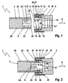
- an electrical plug connection 1 comprises a first plug-in part 2 and a second plug-in part 3.
- the plug-in connection 1 serves for the electrical connection of at least two electrical lines, which are not shown here for the sake of simplicity.
- the first plug-in part 2 contains in its interior a first electrical coupling part 4.
- the second plug-in part 3 contains a second in its interior electrical coupling part 5.
- the second coupling part 5 is formed as a plug 6, while the first coupling part 4 is formed by a bushing 7.
- the two coupling parts 4, 5 are complementary to each other, so that the plug 6 and socket 7 in one symbolized by a double arrow plug-in direction 8 are inserted into one another.
- the plug 6 By inserting the plug 6 in the socket 7, an electrical connection between the coupling parts 4, 5 is made, so that the connected to the coupling parts 4, 5 electrical lines are contacted in a designated manner with each other.
- the plug 6 may contain, for each line to be contacted, a pin 9 which can be inserted into a matching pin receptacle which is formed in the socket 7 and is not shown here. These pin recordings are then connected in a corresponding manner in each case with the associated line.
- the first plug-in part 2 has a receiving sleeve 10 which is arranged coaxially relative to the plug-in direction 8 to the first coupling part 4 and which surrounds the coupling part 4 in an annular manner.
- This receiving sleeve 10 supports a locking element 12 on an inner side 11 facing the first coupling part 4.
- the locking element 12 is a spring ring in the circumferential direction distributed has a plurality of locking tabs 13 which project from an outer periphery of the spring ring 12 inwardly.
- the locking element or the spring ring 12 is adjustable between a locking position, which is shown in FIGS. 1, 2 and 4 and an unlocking position which is shown in FIGS. 5 and 6.
- the locking tabs 13 are resiliently resilient with respect to the insertion direction 8, whereby they can be bent in the direction of insertion 8. In this movement, an inner cross section 14 of the spring ring changes 12. In the locking position, this inner cross section 14 is smaller than in the unlocked position.
- the locking tabs 13 are inclined here as already in the locking position relative to the plug-in direction 8 and indeed with an inclination angle which is smaller than 90 °.
- the inclination of the locking tabs 13 is chosen so that the inclination angle additionally decreases when transferring the locking tabs 13 in the unlocked position. By this orientation of the locking tabs 13, the forces required to adjust the locking tabs 13 in their unlocked position are reduced.
- the design of the spring ring 12 is such that its locking tabs 13 are biased in the locking position. The adjustment of the individual locking tabs 13 in the unlocked position thus takes place against a restoring spring force of the spring ring 12th
- the first male part 2 is also equipped with a sliding sleeve 15, which is also arranged coaxially with the first coupling part 4, wherein the sliding sleeve 15, the first coupling part 4 surrounds annular.
- the sliding sleeve 15 has in the preferred embodiment shown here, a substantially U-shaped profile with two different length U-legs.
- the radially inner U-leg forms an actuating portion 16 of the sliding sleeve 15, while the radially outer U-leg forms a handle portion 17 of the sliding sleeve 15.
- Handle portion 17 and operating portion 16 are interconnected by a collar 18 which extends transversely to the insertion direction 8, the U-base forms the U-base and is disposed adjacent to a front end 19 of the receiving sleeve 10.
- the sliding sleeve 15 is slidably mounted on the receiving sleeve 10 in the insertion direction 8. 1 to 4 each show a rest position of the sliding sleeve 15, while FIGS. 5 and 6 represent a release position of the sliding sleeve 15.
- the actuating portion 16 cooperates with the locking element 12 or with its locking tabs 13.
- the coupling between the sliding sleeve 15 and locking element 12 takes place so that a displacement of the sliding sleeve 15 in its release position corresponding to FIGS. 5 and 6, the locking element 12 and its locking tabs 13 forces in the release position.
- the spring force acting on the locking element 12 ensures that this or its locking lugs 13 independently seek to take their locking position.
- the spring force of the locking element 12 and the locking tabs 13 also causes here that the sliding sleeve 15 is driven by the restoring force of the spring ring 12 in the rest position. Accordingly, the sliding sleeve 15 is automatically moved to its rest position as soon as the locking element 12 can assume its locking position.
- the locking element 12 may preferably occupy its locking position when the two plug-in parts 2, 3 are completely inserted into one another. In any case, the locking element 12 assumes its locking position as soon as the two plug-in parts 2, 3 are separated or removed from each other.
- the second plug-in part 3 has a plug-in tube 20, which is arranged coaxially to the second coupling part 5 with respect to the plug-in direction 8 and surrounds it annularly.
- an annular circumferential locking step 21 is formed on the plug-in tube 20.
- this locking step 21 is produced in that on the outer side 22 of the plug tube 20, a completely circumferential annular groove 23 is formed, wherein the locking step 21 forms one of the axial boundary walls of the annular groove 23.
- plug-in tube 20 in which the plug-in tube 20 is made of plastic, can basically to such Latch level 21 and to be dispensed with such an annular groove 23.
- the two plug-in parts 2, 3 are spaced apart from one another. Immediately before the insertion of the two plug-in parts 2, 3 into each other, they are aligned with respect to the insertion direction 8 in alignment with each other.
- the second plug-in part 3 is plugged into the first plug-in part 2 so far that a leading, front-side end 24 of the second plug-in part 3 comes into contact with the latching tabs 13.
- the locking tabs 13 are still in their locked state.
- the latching lugs 13 are thereby bent over in the plug-in direction, ie in the unlocked position.
- the preceding axial end 24 of the second plug-in part 3 is inserted into the first plug-in part 2 until it makes contact with a seal 25.
- This seal 25 is formed here as an O-ring.
- the second plug-in part 3 has reached its maximum penetration depth into the first plug-in part 2.
- This maximum penetration depth is defined here by a stop 26 which is formed in the first plug-in part by an annular step on which the preceding axial end 24 of the second plug-in part 3 comes to rest axially.
- the spring-loaded locking element 12 can now automatically transition into its locking position in the region of the annular groove 23, as a result of which the locking lugs 13 in the annular groove 23 engage behind the locking step 21. This results in a positive securing of the second plug-in part 3 in the first plug-in part 2 against pulling out.
- the locking element 12 which expediently consists of metal, can be supported with its locking lugs 13 directly on the outside 22 of the plug-in tube 20. Due to the material combination (relatively soft plastic of the plug tube 20 and relatively hard metal of the locking element 12), in this case, in particular in conjunction with relatively sharp-edged locking tabs 13, to a sufficient adhesion between the plug-in parts 2, 3rd
- the predetermined insertion depth between the plug-in parts 2, 3 is, inter alia, chosen so that in each case a proper electrical contact between the coupling elements 4, 5 is ensured. In other words, the pins 9 reach sufficiently deep into the associated pin recordings.
- the actuating portion 16 for unlocking the plug-in parts 2, 3 this acts on its, the locking element 12 facing the end with the locking tabs 13 together. Furthermore, the actuating portion 16 may be bevelled at this end with that inclination, which also have the locking tabs 13 in their unlocked position. Also, the inner wall 11 of the receiving sleeve 10 is chamfered adjacent to the locking element 12 according to this inclination.
- Inner cross section 27 and outer cross section 28 form between the plug tube 20 and receiving sleeve 10 an axial guide. This facilitates the insertion of the plug-in parts 2, 3 finding the connection state.
- This axial guidance is achieved here by the fact that an inner cross section 27 of the sliding sleeve 15 in the region of its actuating portion 16 is about the same size or slightly larger than an outer cross section 28 of the plug tube 20 is selected.
- the plug-in tube 20, the receiving sleeve 10 and the locking element 12 are made of metal.
- the locking element 12 is electrically connected to the outer sleeve 10 radially outside and formed so that it is electrically contacted in the inserted connection state with the plug tube 20.
- the contact with the plug-in tube 20 takes place over several points which are distributed circumferentially, so that almost an annular contact between locking element 12 and plug tube 20 forms.
- the contact between the locking element 12 and receiving sleeve 10 is formed closed annular, since the locking element 12 in an annular recess 29 which is formed on the inner side 11 of the receiving sleeve 10 is inserted.
- the plug connection 1 in the contact state, an electrically conductive connection between plug-in tube 20 and receiving sleeve 10, which completely encloses the electrical contacting of the coupling parts 4, 5.
- the plug connection 1 according to the invention is suitable for EMC and enables a shielding of electromagnetic impulses or disturbances, which can also be derived via the plug tube 20 or via the receiving sleeve 10 from the plug connection 1.
- the plug-in parts 2, 3 are formed in an advantageous embodiment so that they protect the electrical connection of the associated electrical coupling parts 4, 5 from electromagnetic interactions with the environment of the plug-in parts 2, 3 in the connection state.
- the connector 1 is electromagnetically compatible, so that it can be used in EMVsensiblen installation situations.
- EMC stands for E tolerability lektro- M agnetician- V.
- the plug-in parts 2, 3 form so that they shield in the connection state, the electrical connection of the coupling parts 4, 5 against electromagnetic interference and electromagnetic interference of he electrical connection of the coupling parts 4, 5 derived.
- the shielding and dissipation of electromagnetic interference also improves the electromagnetic compatibility of the connector 1. Electromagnetic interference, which arise in the vicinity of the connector 1, can not act in the electrical connection of the coupling parts 4, 5, nor can electromagnetic interference, which is within the propagate by means of the connector 1 interconnected lines, get from the connector 1 in their environment. The derivation of the electromagnetic interference ensures that the interference can not add up to impermissibly high values.
- the EMC capability of the connector 1 or the dense shielding of the connector in combination with the immediate dissipation of the interference can be realized in the connector 1 as shown, for example, characterized in that the receiving sleeve 10, the plug tube 20 and the locking element 12 are formed of metal , wherein the locking element 12 is electrically connected to the receiving sleeve 10 and electrically contacted in the connecting state of the plug-in tube 20 circumferentially distributed in several places.
- the desired EMC capability or the desired shielding and dissipation can be achieved virtually without additional effort, since the electrically conductive locking element 12 allows a highly effective circumferential contact between the plug-in parts 2, 3 in the connection state.
- the sliding sleeve 15 does not have to be involved in the electrical contacting between the plug-in tube 20 and the receiving sleeve 10, the sliding sleeve 15 can be suitably made of a plastic.
- Fig. 7 shows a variant of the connector 1 according to the invention, in which the sliding sleeve 15 is held captively in a different manner on the first plug-in part 2 as in the embodiment of Fig. 1 to 6. Further, in this embodiment, the plug tube 20 on its outside 22 provided with an external thread 30. The positioning of the external thread 30 is chosen so that it has no interaction with the receiving sleeve 10 or with the sliding sleeve 15 in the connection state shown in FIG.
- the connector 1 according to the invention with respect to the second plug-in part 3 backward compatible, that is, the second plug-in part 3 of the connector 1 according to the invention can be used in conjunction with a conventional first plug-in part 2 'shown in FIG Union nut 31 is equipped, which cooperates with the male thread 30 after the insertion of the coupling parts 4, 5, to secure the two plug-in parts 2 'and 3 to each other.
- FIGS. 9 and 10 illustrate another embodiment in which the first coupling part 4 arranged in the first plug part 2 is now formed as a plug 6, in contrast to the previous embodiments the second coupling part 5 of the second plug-in part 3 is designed as a socket 7.
- the plug-in tube 20 is equipped in this embodiment with an internal thread 32, so that the second plug-in part 3 with a conventional, not shown here first plug (standard plug) is used , which is provided with a corresponding external thread.
- first plug standard plug
- here also contains the second male part 3, a seal 33 which cooperates in the connection state with a standard connector. In conjunction with the first plug-in part 2, this seal 33 is in accordance with FIG. 10 in itself functionless.
- the locking element 12 in the form of a spring ring.
- the locking element or the spring ring 12 in this case has a closed outer ring 34, from which the individual locking tabs 13 project radially inwards from the inside.
- the locking element 12 can be particularly simple, e.g. as a punching element. In principle, other designs for the locking element 12 are conceivable.
- the locking tabs 13 may be provided with recesses so as to vary the spring stiffness of the spring ring 12 and the locking tabs 13.
- Both the first plug-in part 2 and the second plug-in part 3 can be manufactured so that after their production their coupling parts 4, 5 are already firmly connected to the respective lines.
- both plug-in parts 2, 3 can each be attached to one end of a cable 35 (see FIGS. 9 and 10), in which the electrical leads leading to the individual contacts of the respective coupling part 4, 5 are combined.
- a cable 35 see FIGS. 9 and 10
- at least one of the plug-in parts 2, 3 forms a base which is fixedly installed in a housing of an electrical device.
- FIGS. 12 to 14 Further particularities of the present connector 1 are shown in FIGS. 12 to 14, some of which are also present in the preceding embodiments and will be explained in more detail below.
- the connector 1 is made, that is, the two plug-in parts 2, 3 are completely inserted into one another. Accordingly engages the locking element 12 (with its locking tabs 13) in the annular groove 23 a.
- the two plug-in parts 2, 3 and annular groove 23 and locking element 12 are coordinated so that the locking element 12 can assume its locking position in this security state.
- FIGS. 12 to 14 the connector 1 is made, that is, the two plug-in parts 2, 3 are completely inserted into one another. Accordingly engages the locking element 12 (with its locking tabs 13) in the annular groove 23 a.
- the two plug-in parts 2, 3 and annular groove 23 and locking element 12 are coordinated so that the locking element 12 can assume its locking position in this security state.
- the axial displaceability of the sliding sleeve 15 is so on the elastic adjustment of the locking element Matched 12 that the driven by the locking element 12 sliding sleeve 15 assumes its rest position when the locking element 12 is in its locking position. This is achieved by means of an axial stop 36, which defines the rest position of the sliding sleeve 15. against this axial stop 36, the locking element 12 presses the sliding sleeve 15 adjacent.
- the sliding sleeve 15 is supported on the inner side 11 on the receiving sleeve 10. This results in particular a protected from contamination position for the holder, which ensures a long operability of the sliding sleeve 15 and thus the connector 1.
- the sliding sleeve 15 is held by means of at least one latching 37 on the receiving sleeve 10.
- the catch 37 simultaneously forms the abovementioned axial stop 36, which defines the rest position of the sliding sleeve 15.
- Each of the mentioned catches 37 comprises at least one latching edge, which is designated 38 for maintaining the overview only in FIGS. 12 to 14. Furthermore, each catch 37 comprises a latching contour, which is designated 39 for maintaining the overview only in FIGS. 12 to 14. In the rest position of the sliding sleeve 15, the respective locking edge 38 is located on the respective latching contour 39 axially, thereby the axial stop 36 is formed. A special feature of this latching 37 is seen in the fact that each locking edge 38 is axially removable from the respective latching contour 39 in order to convert the sliding sleeve 15 in its unlocked position can.
- the respective latching edge 38 can be formed either by a single, circumferentially closed annular circumferential locking edge 38 or by a plurality of circumferentially distributed locking edges 38. The same applies to the latching contour 39.
- the latching 37 is formed at an end remote from the actuating portion 16 of the sliding sleeve 15.
- the associated latching contour 39 is in this case formed on the receiving sleeve 10, but may also be formed in another embodiment on the first plug-in part 2.
- the latching 37 is formed on an outer side 40 of the receiving sleeve 10, which faces away from the first coupling part 4.
- the latching 37 is formed radially between the sliding sleeve 15 and the receiving sleeve 10. In this way, an internal latching 37 or an inner holder of the sliding sleeve 15 is achieved on the receiving sleeve 10 in this embodiment, which is advantageous against contamination is protected.
- the latching edge 38 engages in a groove 41, which is bounded axially by the latching contour 39.
- the groove 41 is formed on an inner side of the sliding sleeve 15, while the at least one latching edge 38 projects outwardly from the outer side 40 of the receiving sleeve 10.
- the groove may also be formed on the outer side 40 of the receiving sleeve 10, while the at least one associated latching edge then projects inwards on the inner side of the sliding sleeve 15.
- the latching 37 is formed on the inner side 11 of the receiving sleeve 10, specifically radially between the actuating portion 16 and the receiving sleeve 10.
- the sliding sleeve 15 at its operating portion 16 at least one outwardly projecting Locking edge 38, which engages behind the formed on the inside 11 of the receiving sleeve 10 locking contour 39.
- the at least one locking edge 38 could also be formed on the receiving sleeve 10, while then the associated locking contour 39 would be provided on the actuating portion 16.
- the latching 37 is completely within the sliding sleeve 15 and within the receiving sleeve 10, whereby the latching 37 is particularly well protected from contamination.
- FIGS. 12 to 14 are also characterized by another feature.
- the receiving sleeve 10 is in each case with respect configured on the first male part 2 as a separate component.
- This separate receiving sleeve 10 is mounted coaxially outside the first plug-in part 2.
- the receiving sleeve 10 could be screwed onto the first plug-in part 2, for which purpose the receiving sleeve 10 and the first plug-in part 2 would have to be provided with mutually complementary threads.
- the embodiment shown here is preferred in which the first plug-in part 2 has an outer toothing 42 on an outer side facing the receiving sleeve 10.
- the receiving sleeve 10 has on its inner side facing the first plug-in part 2 inside a corresponding internal toothing 43.
- the receiving sleeve 10 is configured such that it can be axially plugged onto the first plug-in part 2.
- the complementary teeth 42, 43 engage in one another in a form-fitting manner and prevent or impede removal of the receiving sleeve 10 from the first plug-in part 2.
- the design of the receiving sleeve 10 as a separate component results in easier assembly.
- the receiving sleeve 10 in this embodiment consists of a plastic.
Landscapes
- Details Of Connecting Devices For Male And Female Coupling (AREA)
- Quick-Acting Or Multi-Walled Pipe Joints (AREA)
Applications Claiming Priority (2)
| Application Number | Priority Date | Filing Date | Title |
|---|---|---|---|
| DE10324794A DE10324794B3 (de) | 2003-05-31 | 2003-05-31 | Elektrische Steckverbindung |
| PCT/DE2004/000793 WO2004109865A1 (de) | 2003-05-31 | 2004-04-14 | Elektrische steckverbindung |
Publications (2)
| Publication Number | Publication Date |
|---|---|
| EP1629573A1 EP1629573A1 (de) | 2006-03-01 |
| EP1629573B1 true EP1629573B1 (de) | 2007-07-04 |
Family
ID=33441547
Family Applications (1)
| Application Number | Title | Priority Date | Filing Date |
|---|---|---|---|
| EP04727232A Expired - Lifetime EP1629573B1 (de) | 2003-05-31 | 2004-04-14 | Elektrische steckverbindung |
Country Status (10)
| Country | Link |
|---|---|
| US (1) | US7695302B2 (ko) |
| EP (1) | EP1629573B1 (ko) |
| JP (2) | JP2006526262A (ko) |
| KR (1) | KR20060026857A (ko) |
| CN (1) | CN1799170B (ko) |
| AT (1) | ATE366468T1 (ko) |
| AU (1) | AU2004246315A1 (ko) |
| CA (1) | CA2527899C (ko) |
| DE (2) | DE10324794B3 (ko) |
| WO (1) | WO2004109865A1 (ko) |
Cited By (1)
| Publication number | Priority date | Publication date | Assignee | Title |
|---|---|---|---|---|
| DE202017006920U1 (de) | 2017-10-23 | 2018-11-09 | Phoenix Contact Gmbh & Co. Kg | Steckverbinderteil mit einer Spiralfeder zum axialen Vorspannen eines Gegensteckverbinderteils |
Families Citing this family (51)
| Publication number | Priority date | Publication date | Assignee | Title |
|---|---|---|---|---|
| DE10324794B3 (de) * | 2003-05-31 | 2004-12-09 | Woodhead Connectivity Gmbh | Elektrische Steckverbindung |
| ITGE20060051A1 (it) * | 2006-05-05 | 2007-11-06 | Hypertac S P A | Dispositivo di connessione per collegamenti elettrici od elettronici. |
| CN200973086Y (zh) * | 2006-08-16 | 2007-11-07 | 西安科耐特科技有限责任公司 | 快插自锁射频同轴连接器 |
| US9431763B2 (en) | 2010-04-15 | 2016-08-30 | Zonit Structured Solutions, Llc | Frictional locking receptacle with release operated by actuator |
| EP2142951B1 (en) | 2007-04-20 | 2015-04-01 | Huber+Suhner AG | Optical connector |
| JP4795381B2 (ja) * | 2008-05-01 | 2011-10-19 | タイコエレクトロニクスジャパン合同会社 | 電気コネクタ組立体 |
| DE202008011017U1 (de) | 2008-08-18 | 2008-10-16 | Fischer Connectors Holding S.A. | Elektrische Steckverbindung |
| EP2337163B1 (en) | 2008-10-01 | 2020-07-29 | Fujitsu Limited | Connector, electronic apparatus, method for removing connector |
| EP2302744B1 (en) * | 2009-09-24 | 2012-06-20 | Tyco Electronics France SAS | Electrical socket with supporting element, electrical plug with deformation pocket and plug assembly with at least one socket and one plug as well as a method for connecting a plug and a socket |
| GB2475089B (en) * | 2009-11-05 | 2014-09-24 | Connectors Ltd Ab | Connector assembly and a connector part thereof |
| DE102010027524A1 (de) * | 2010-07-16 | 2012-01-19 | Phoenix Contact Gmbh & Co. Kg | Gehäuse, insbesondere für einen elektrischen Kabelanschluss |
| DE102010045921A1 (de) * | 2010-09-21 | 2012-03-22 | Auto-Kabel Managementgesellschaft Mbh | Elektrisches Verbindungssystem einer Energiegewinnungseinrichtung |
| CN102082362B (zh) * | 2010-12-16 | 2012-08-22 | 郑州煤矿机械集团股份有限公司 | 一次扣压成型式电缆连接器 |
| DE102012203459A1 (de) * | 2011-11-09 | 2013-05-16 | Lq Mechatronik-Systeme Gmbh | Mehrpolige Steckverbindungseinheit für Dreiphasen-Wechselstromsysteme |
| JP6044881B2 (ja) * | 2011-11-22 | 2016-12-14 | パナソニックIpマネジメント株式会社 | 給電制御装置 |
| EP2926416B1 (en) | 2012-11-30 | 2018-05-23 | Bal Seal Engineering, Inc. | Spring connectors with adjustable grooves and related methods |
| US11581682B2 (en) | 2013-03-15 | 2023-02-14 | Zonit Structured Solutions, Llc | Frictional locking receptacle with programmable release |
| US8944838B2 (en) * | 2013-04-10 | 2015-02-03 | Tyco Electronics Corporation | Connector with locking ring |
| CN103401099B (zh) * | 2013-08-06 | 2015-10-14 | 临沂市海纳电子有限公司 | 一种带有屏蔽接触簧的连接器 |
| EP3044839B1 (en) * | 2013-09-12 | 2019-07-10 | Vertiv Corporation | Apparatus for retaining plug in a receptacle |
| CA2922762C (en) * | 2013-09-12 | 2020-06-09 | Pce, Inc. | Apparatus for retaining plug in a receptacle |
| CN104218383B (zh) * | 2013-09-16 | 2017-03-22 | 中航光电科技股份有限公司 | 电连接器壳体组件和电连接器组件 |
| KR101362854B1 (ko) | 2013-10-29 | 2014-02-14 | 엘아이지넥스원 주식회사 | 연결 장치 |
| CN104158022A (zh) * | 2014-06-03 | 2014-11-19 | 苏州瑞可达连接系统股份有限公司 | 塔放连接器 |
| KR101659415B1 (ko) * | 2014-12-16 | 2016-09-30 | 한국생산기술연구원 | 스마트 기저귀 |
| KR101681650B1 (ko) * | 2014-12-23 | 2016-12-02 | 주식회사 케이제이컴텍 | 상호변조 방지용 qn형 커넥터 |
| CN105356149B (zh) * | 2015-12-04 | 2019-01-18 | 中国电子科技集团公司第四十研究所 | 推入自锁式射频连接器 |
| JP6453272B2 (ja) * | 2016-06-07 | 2019-01-16 | タイコエレクトロニクスジャパン合同会社 | コネクタおよびコネクタ組立体 |
| US10205281B2 (en) * | 2016-09-20 | 2019-02-12 | Vertiv Corporation | Apparatus for retaining a plug within a receptacle |
| CN106428092B (zh) * | 2016-11-01 | 2018-12-04 | 崔建国 | 机车后视自动转换电连接器的应用系统 |
| DE102017200741B4 (de) | 2017-01-18 | 2022-03-24 | Ifm Electronic Gmbh | Rundsteckverbinder zur elektrischen Verbindung und mechanischen Verriegelung mit einem Standardgegenstück |
| JP7263257B2 (ja) * | 2017-02-21 | 2023-04-24 | マイクロベンション インコーポレイテッド | 電気カテーテル |
| US10950994B2 (en) * | 2017-03-10 | 2021-03-16 | John Mezzalinguaassociates, Llc | Quick connect/disconnect coaxial cable connector |
| CN106887774B (zh) * | 2017-04-07 | 2017-12-26 | 王祎玮 | 一种环保除尘装置 |
| DE102017117679B4 (de) * | 2017-08-03 | 2019-06-13 | Ims Connector Systems Gmbh | Elektrischer Steckverbinder |
| DE102017122245A1 (de) * | 2017-09-26 | 2019-03-28 | Harting Electric Gmbh & Co. Kg | Steckverbinder mit Arretierung |
| DE102017127991B4 (de) * | 2017-11-27 | 2021-06-10 | HARTING Electronics GmbH | Ver- und entriegelbarer Steckverbinder |
| DE102018100910A1 (de) | 2018-01-17 | 2019-07-18 | Ifm Electronic Gmbh | Rundsteckverbinder zur elektrischen Verbindung und mechanischen Verriegelung mit einem Standardgegenstück |
| JP6930467B2 (ja) | 2018-03-14 | 2021-09-01 | オムロン株式会社 | コネクタ |
| EP3544125B1 (en) * | 2018-03-19 | 2022-12-07 | Tyco Electronics AMP Korea Co., Ltd. | Connector assembly comprising a male connector |
| CN108709244A (zh) * | 2018-06-26 | 2018-10-26 | 上海晶成电气有限公司 | 空调风机盘管与控制器的快速连接结构及空调的集控系统 |
| KR102173220B1 (ko) * | 2018-08-30 | 2020-11-03 | 옵티시스 주식회사 | 접속용 커넥팅 장치 |
| KR102228479B1 (ko) * | 2018-08-30 | 2021-03-16 | 옵티시스 주식회사 | 접속용 커넥팅 장치 |
| CN110783768B (zh) * | 2018-12-30 | 2020-11-06 | 乐清市然景电气有限公司 | 一种用于彩超机的数据接口插座 |
| CN110086036A (zh) * | 2019-05-07 | 2019-08-02 | 上海航天科工电器研究院有限公司 | 一种双层密封二次解锁电磁脱离的连接器 |
| CN112003077A (zh) * | 2019-05-25 | 2020-11-27 | 费斯托股份两合公司 | 用于电连接的联接系统 |
| US11953166B2 (en) | 2019-11-25 | 2024-04-09 | Molex, Llc | LED lighting fixture with interconnect |
| CN111391685B (zh) * | 2020-03-31 | 2021-09-28 | 深圳供电局有限公司 | 充电装置 |
| CN113332130A (zh) * | 2021-06-08 | 2021-09-03 | 吉林大学 | 一种女性生殖器护理清洁装置 |
| DE102022117860B3 (de) | 2022-07-18 | 2023-07-27 | Ifm Electronic Gmbh | Buchsenteil für eine elektrische Steckverbindung und elektronische Steuereinheit mit einem derartigen Buchsenteil |
| CN117578112B (zh) * | 2024-01-17 | 2024-03-26 | 东莞市康顺连接科技有限公司 | 一种网络通讯连接器 |
Family Cites Families (15)
| Publication number | Priority date | Publication date | Assignee | Title |
|---|---|---|---|---|
| DE1951180U (de) * | 1966-07-20 | 1966-12-08 | Georg Dr Ing Spinner | Hf-koaxialsteckverbindung mit schnappverschluss. |
| FR2204331A5 (ko) * | 1972-10-24 | 1974-05-17 | Radiall Sa | |
| FR2492598A1 (fr) * | 1980-10-22 | 1982-04-23 | Radiall Sa | Connecteur electrique a verrouillage et deverrouillage rapides |
| US4423919A (en) * | 1982-04-05 | 1984-01-03 | The Bendix Corporation | Electrical connector |
| FR2670615B1 (fr) * | 1990-12-18 | 1993-02-19 | Radiall Sa | Connecteur electrique coaxial. |
| DE4325895C1 (de) * | 1993-08-02 | 1994-12-22 | Contact Gmbh | Steckverbinderpaar |
| US5695224A (en) * | 1995-08-14 | 1997-12-09 | The Rovac Corporation | Pipe joint assembly |
| DE19749130C1 (de) * | 1997-11-06 | 1999-08-26 | Siemens Ag | Elektrischer Steckverbinder mit Schnellverriegelung |
| KR200246718Y1 (ko) * | 1998-06-02 | 2001-12-17 | 김덕용 | 커넥터체결장치 |
| DE29911792U1 (de) * | 1999-07-07 | 1999-10-28 | Coninvers Elektronische Bauele | Variabler Kabelverbinder |
| DE10117738C1 (de) * | 2001-04-09 | 2002-10-17 | Bartec Componenten & Syst Gmbh | Steckverbindung |
| FR2828343B1 (fr) * | 2001-08-03 | 2004-06-11 | Radiall Sa | Connecteur coaxial a verrouillage par encliquetage |
| WO2003021720A1 (en) * | 2001-09-04 | 2003-03-13 | Woodhead Industries, Inc. | Vibration resistant electrical connector |
| ATE325446T1 (de) * | 2002-02-14 | 2006-06-15 | Radiall Sa | Elektrischer steckverbinder |
| DE10324794B3 (de) * | 2003-05-31 | 2004-12-09 | Woodhead Connectivity Gmbh | Elektrische Steckverbindung |
-
2003
- 2003-05-31 DE DE10324794A patent/DE10324794B3/de not_active Expired - Fee Related
-
2004
- 2004-04-14 DE DE502004004244T patent/DE502004004244D1/de not_active Expired - Lifetime
- 2004-04-14 CN CN2004800148709A patent/CN1799170B/zh not_active Expired - Lifetime
- 2004-04-14 AU AU2004246315A patent/AU2004246315A1/en not_active Abandoned
- 2004-04-14 WO PCT/DE2004/000793 patent/WO2004109865A1/de active Application Filing
- 2004-04-14 JP JP2006508106A patent/JP2006526262A/ja active Pending
- 2004-04-14 US US10/557,057 patent/US7695302B2/en active Active
- 2004-04-14 KR KR1020057022799A patent/KR20060026857A/ko not_active Application Discontinuation
- 2004-04-14 AT AT04727232T patent/ATE366468T1/de not_active IP Right Cessation
- 2004-04-14 CA CA002527899A patent/CA2527899C/en not_active Expired - Lifetime
- 2004-04-14 EP EP04727232A patent/EP1629573B1/de not_active Expired - Lifetime
-
2008
- 2008-07-30 JP JP2008196628A patent/JP4732492B2/ja not_active Expired - Fee Related
Cited By (1)
| Publication number | Priority date | Publication date | Assignee | Title |
|---|---|---|---|---|
| DE202017006920U1 (de) | 2017-10-23 | 2018-11-09 | Phoenix Contact Gmbh & Co. Kg | Steckverbinderteil mit einer Spiralfeder zum axialen Vorspannen eines Gegensteckverbinderteils |
Also Published As
| Publication number | Publication date |
|---|---|
| ATE366468T1 (de) | 2007-07-15 |
| WO2004109865A1 (de) | 2004-12-16 |
| CN1799170A (zh) | 2006-07-05 |
| EP1629573A1 (de) | 2006-03-01 |
| JP4732492B2 (ja) | 2011-07-27 |
| KR20060026857A (ko) | 2006-03-24 |
| AU2004246315A1 (en) | 2004-12-16 |
| CN1799170B (zh) | 2012-07-18 |
| US7695302B2 (en) | 2010-04-13 |
| US20080207040A1 (en) | 2008-08-28 |
| DE502004004244D1 (de) | 2007-08-16 |
| DE10324794B3 (de) | 2004-12-09 |
| JP2006526262A (ja) | 2006-11-16 |
| CA2527899C (en) | 2008-08-12 |
| CA2527899A1 (en) | 2004-12-16 |
| JP2009004381A (ja) | 2009-01-08 |
Similar Documents
| Publication | Publication Date | Title |
|---|---|---|
| EP1629573B1 (de) | Elektrische steckverbindung | |
| DE2826456A1 (de) | Elektrischer verbinder mit entstoerfilter | |
| EP2439439B1 (de) | Verbindungselement für eine Fluidverbindung | |
| DE102009016227B4 (de) | Steckverbinder mit einem angebundenen Koaxialkabel | |
| EP1662620A2 (de) | Elektrische Steckverbindung | |
| DE102005032022B4 (de) | Verbinder | |
| EP1099278B1 (de) | Elektrischer steckverbinder mit schnellverbindung und verfahren zur herstellung eines steckverbinders | |
| DE202009009807U1 (de) | Manipulationssichere Kabeldurchführung | |
| DE2323180A1 (de) | Verriegelung fuer einen elektrischen steckverbinder | |
| DE102007005737A1 (de) | Kopfstützensystem für einen Fahrzeugsitz | |
| WO2015104117A1 (de) | Vorrichtung zur fixierung einer elektrischen leitung in einem stecker, stecker für eine elektrische leitung sowie elektrisches kabel | |
| EP3352309B1 (de) | Abgedichteter steckverbinder | |
| DE202017006920U1 (de) | Steckverbinderteil mit einer Spiralfeder zum axialen Vorspannen eines Gegensteckverbinderteils | |
| EP2780986B1 (de) | Steckverbindung | |
| DE102018126448A1 (de) | Elektrischer Steckverbinder und elektrische Steckverbindung | |
| DE102011050574A1 (de) | Anschlussverbinder | |
| DE102007011794A1 (de) | Steckverbinder | |
| DE10326834B4 (de) | Steckverbinder | |
| DE102006036097B3 (de) | Steckverbinder, Anordnung mit Steckverbinder und Verfahren zur Montage | |
| DE102017119643A1 (de) | Komplett abgedichteter Steckverbinder mit verbesserten Haltekräften | |
| DE10206063B4 (de) | Anbau-Steckvorrichtung | |
| WO2020025250A1 (de) | Steckvorrichtung mit verrastbaren komponenten | |
| DE102019127345A1 (de) | Einstellvorrichtung für einen Scheinwerfer | |
| WO2015169487A1 (de) | Kontaktelement | |
| EP3703198B1 (de) | Anschlussvorrichtung, steckverbindung und verfahren zur herstellung einer steckverbindung |
Legal Events
| Date | Code | Title | Description |
|---|---|---|---|
| PUAI | Public reference made under article 153(3) epc to a published international application that has entered the european phase |
Free format text: ORIGINAL CODE: 0009012 |
|
| 17P | Request for examination filed |
Effective date: 20050922 |
|
| AK | Designated contracting states |
Kind code of ref document: A1 Designated state(s): AT BE BG CH CY CZ DE DK EE ES FI FR GB GR HU IE IT LI LU MC NL PL PT RO SE SI SK TR |
|
| DAX | Request for extension of the european patent (deleted) | ||
| GRAP | Despatch of communication of intention to grant a patent |
Free format text: ORIGINAL CODE: EPIDOSNIGR1 |
|
| GRAS | Grant fee paid |
Free format text: ORIGINAL CODE: EPIDOSNIGR3 |
|
| GRAA | (expected) grant |
Free format text: ORIGINAL CODE: 0009210 |
|
| AK | Designated contracting states |
Kind code of ref document: B1 Designated state(s): AT BE BG CH CY CZ DE DK EE ES FI FR GB GR HU IE IT LI LU MC NL PL PT RO SE SI SK TR |
|
| REG | Reference to a national code |
Ref country code: GB Ref legal event code: FG4D Free format text: NOT ENGLISH |
|
| REG | Reference to a national code |
Ref country code: CH Ref legal event code: EP |
|
| REG | Reference to a national code |
Ref country code: IE Ref legal event code: FG4D Free format text: LANGUAGE OF EP DOCUMENT: GERMAN |
|
| REF | Corresponds to: |
Ref document number: 502004004244 Country of ref document: DE Date of ref document: 20070816 Kind code of ref document: P |
|
| NLV1 | Nl: lapsed or annulled due to failure to fulfill the requirements of art. 29p and 29m of the patents act | ||
| GBV | Gb: ep patent (uk) treated as always having been void in accordance with gb section 77(7)/1977 [no translation filed] |
Effective date: 20070704 |
|
| PG25 | Lapsed in a contracting state [announced via postgrant information from national office to epo] |
Ref country code: FI Free format text: LAPSE BECAUSE OF FAILURE TO SUBMIT A TRANSLATION OF THE DESCRIPTION OR TO PAY THE FEE WITHIN THE PRESCRIBED TIME-LIMIT Effective date: 20070704 Ref country code: ES Free format text: LAPSE BECAUSE OF FAILURE TO SUBMIT A TRANSLATION OF THE DESCRIPTION OR TO PAY THE FEE WITHIN THE PRESCRIBED TIME-LIMIT Effective date: 20071015 Ref country code: BG Free format text: LAPSE BECAUSE OF FAILURE TO SUBMIT A TRANSLATION OF THE DESCRIPTION OR TO PAY THE FEE WITHIN THE PRESCRIBED TIME-LIMIT Effective date: 20071004 Ref country code: SI Free format text: LAPSE BECAUSE OF FAILURE TO SUBMIT A TRANSLATION OF THE DESCRIPTION OR TO PAY THE FEE WITHIN THE PRESCRIBED TIME-LIMIT Effective date: 20070704 Ref country code: PT Free format text: LAPSE BECAUSE OF FAILURE TO SUBMIT A TRANSLATION OF THE DESCRIPTION OR TO PAY THE FEE WITHIN THE PRESCRIBED TIME-LIMIT Effective date: 20071204 Ref country code: NL Free format text: LAPSE BECAUSE OF FAILURE TO SUBMIT A TRANSLATION OF THE DESCRIPTION OR TO PAY THE FEE WITHIN THE PRESCRIBED TIME-LIMIT Effective date: 20070704 |
|
| EN | Fr: translation not filed | ||
| PG25 | Lapsed in a contracting state [announced via postgrant information from national office to epo] |
Ref country code: PL Free format text: LAPSE BECAUSE OF FAILURE TO SUBMIT A TRANSLATION OF THE DESCRIPTION OR TO PAY THE FEE WITHIN THE PRESCRIBED TIME-LIMIT Effective date: 20070704 |
|
| REG | Reference to a national code |
Ref country code: IE Ref legal event code: FD4D |
|
| PG25 | Lapsed in a contracting state [announced via postgrant information from national office to epo] |
Ref country code: DK Free format text: LAPSE BECAUSE OF FAILURE TO SUBMIT A TRANSLATION OF THE DESCRIPTION OR TO PAY THE FEE WITHIN THE PRESCRIBED TIME-LIMIT Effective date: 20070704 Ref country code: GR Free format text: LAPSE BECAUSE OF FAILURE TO SUBMIT A TRANSLATION OF THE DESCRIPTION OR TO PAY THE FEE WITHIN THE PRESCRIBED TIME-LIMIT Effective date: 20071005 |
|
| PLBE | No opposition filed within time limit |
Free format text: ORIGINAL CODE: 0009261 |
|
| STAA | Information on the status of an ep patent application or granted ep patent |
Free format text: STATUS: NO OPPOSITION FILED WITHIN TIME LIMIT |
|
| PG25 | Lapsed in a contracting state [announced via postgrant information from national office to epo] |
Ref country code: IE Free format text: LAPSE BECAUSE OF FAILURE TO SUBMIT A TRANSLATION OF THE DESCRIPTION OR TO PAY THE FEE WITHIN THE PRESCRIBED TIME-LIMIT Effective date: 20070704 Ref country code: GB Free format text: LAPSE BECAUSE OF FAILURE TO SUBMIT A TRANSLATION OF THE DESCRIPTION OR TO PAY THE FEE WITHIN THE PRESCRIBED TIME-LIMIT Effective date: 20070704 Ref country code: CZ Free format text: LAPSE BECAUSE OF FAILURE TO SUBMIT A TRANSLATION OF THE DESCRIPTION OR TO PAY THE FEE WITHIN THE PRESCRIBED TIME-LIMIT Effective date: 20070704 Ref country code: SK Free format text: LAPSE BECAUSE OF FAILURE TO SUBMIT A TRANSLATION OF THE DESCRIPTION OR TO PAY THE FEE WITHIN THE PRESCRIBED TIME-LIMIT Effective date: 20070704 |
|
| 26N | No opposition filed |
Effective date: 20080407 |
|
| PG25 | Lapsed in a contracting state [announced via postgrant information from national office to epo] |
Ref country code: SE Free format text: LAPSE BECAUSE OF FAILURE TO SUBMIT A TRANSLATION OF THE DESCRIPTION OR TO PAY THE FEE WITHIN THE PRESCRIBED TIME-LIMIT Effective date: 20071004 Ref country code: RO Free format text: LAPSE BECAUSE OF FAILURE TO SUBMIT A TRANSLATION OF THE DESCRIPTION OR TO PAY THE FEE WITHIN THE PRESCRIBED TIME-LIMIT Effective date: 20070704 |
|
| PG25 | Lapsed in a contracting state [announced via postgrant information from national office to epo] |
Ref country code: FR Free format text: LAPSE BECAUSE OF FAILURE TO SUBMIT A TRANSLATION OF THE DESCRIPTION OR TO PAY THE FEE WITHIN THE PRESCRIBED TIME-LIMIT Effective date: 20080229 |
|
| BERE | Be: lapsed |
Owner name: WOODHEAD CONNECTIVITY G.M.B.H. Effective date: 20080430 |
|
| PG25 | Lapsed in a contracting state [announced via postgrant information from national office to epo] |
Ref country code: MC Free format text: LAPSE BECAUSE OF NON-PAYMENT OF DUE FEES Effective date: 20080430 |
|
| PG25 | Lapsed in a contracting state [announced via postgrant information from national office to epo] |
Ref country code: EE Free format text: LAPSE BECAUSE OF FAILURE TO SUBMIT A TRANSLATION OF THE DESCRIPTION OR TO PAY THE FEE WITHIN THE PRESCRIBED TIME-LIMIT Effective date: 20070704 |
|
| PG25 | Lapsed in a contracting state [announced via postgrant information from national office to epo] |
Ref country code: BE Free format text: LAPSE BECAUSE OF NON-PAYMENT OF DUE FEES Effective date: 20080430 |
|
| PG25 | Lapsed in a contracting state [announced via postgrant information from national office to epo] |
Ref country code: CY Free format text: LAPSE BECAUSE OF FAILURE TO SUBMIT A TRANSLATION OF THE DESCRIPTION OR TO PAY THE FEE WITHIN THE PRESCRIBED TIME-LIMIT Effective date: 20070704 |
|
| PG25 | Lapsed in a contracting state [announced via postgrant information from national office to epo] |
Ref country code: AT Free format text: LAPSE BECAUSE OF NON-PAYMENT OF DUE FEES Effective date: 20080414 |
|
| PG25 | Lapsed in a contracting state [announced via postgrant information from national office to epo] |
Ref country code: LU Free format text: LAPSE BECAUSE OF NON-PAYMENT OF DUE FEES Effective date: 20080414 Ref country code: HU Free format text: LAPSE BECAUSE OF FAILURE TO SUBMIT A TRANSLATION OF THE DESCRIPTION OR TO PAY THE FEE WITHIN THE PRESCRIBED TIME-LIMIT Effective date: 20080105 |
|
| PG25 | Lapsed in a contracting state [announced via postgrant information from national office to epo] |
Ref country code: TR Free format text: LAPSE BECAUSE OF FAILURE TO SUBMIT A TRANSLATION OF THE DESCRIPTION OR TO PAY THE FEE WITHIN THE PRESCRIBED TIME-LIMIT Effective date: 20070704 |
|
| PGFP | Annual fee paid to national office [announced via postgrant information from national office to epo] |
Ref country code: DE Payment date: 20120402 Year of fee payment: 9 |
|
| PGFP | Annual fee paid to national office [announced via postgrant information from national office to epo] |
Ref country code: IT Payment date: 20120421 Year of fee payment: 9 |
|
| PG25 | Lapsed in a contracting state [announced via postgrant information from national office to epo] |
Ref country code: DE Free format text: LAPSE BECAUSE OF NON-PAYMENT OF DUE FEES Effective date: 20131101 |
|
| REG | Reference to a national code |
Ref country code: DE Ref legal event code: R119 Ref document number: 502004004244 Country of ref document: DE Effective date: 20131101 |
|
| PG25 | Lapsed in a contracting state [announced via postgrant information from national office to epo] |
Ref country code: IT Free format text: LAPSE BECAUSE OF NON-PAYMENT OF DUE FEES Effective date: 20130414 |
|
| REG | Reference to a national code |
Ref country code: CH Ref legal event code: PUE Owner name: WOODHEAD INDUSTRIES, LLC, US Free format text: FORMER OWNER: WOODHEAD CONNECTIVITY GMBH, DE |
|
| PGFP | Annual fee paid to national office [announced via postgrant information from national office to epo] |
Ref country code: CH Payment date: 20230502 Year of fee payment: 20 |
|
| REG | Reference to a national code |
Ref country code: CH Ref legal event code: PL |