EP1624348A2 - Bilderzeugungsvorrichtung und -verfahren - Google Patents
Bilderzeugungsvorrichtung und -verfahren Download PDFInfo
- Publication number
- EP1624348A2 EP1624348A2 EP05016670A EP05016670A EP1624348A2 EP 1624348 A2 EP1624348 A2 EP 1624348A2 EP 05016670 A EP05016670 A EP 05016670A EP 05016670 A EP05016670 A EP 05016670A EP 1624348 A2 EP1624348 A2 EP 1624348A2
- Authority
- EP
- European Patent Office
- Prior art keywords
- image
- potential
- abnormal discharge
- image forming
- forming apparatus
- Prior art date
- Legal status (The legal status is an assumption and is not a legal conclusion. Google has not performed a legal analysis and makes no representation as to the accuracy of the status listed.)
- Withdrawn
Links
Images




Classifications
-
- G—PHYSICS
- G03—PHOTOGRAPHY; CINEMATOGRAPHY; ANALOGOUS TECHNIQUES USING WAVES OTHER THAN OPTICAL WAVES; ELECTROGRAPHY; HOLOGRAPHY
- G03G—ELECTROGRAPHY; ELECTROPHOTOGRAPHY; MAGNETOGRAPHY
- G03G15/00—Apparatus for electrographic processes using a charge pattern
- G03G15/14—Apparatus for electrographic processes using a charge pattern for transferring a pattern to a second base
- G03G15/16—Apparatus for electrographic processes using a charge pattern for transferring a pattern to a second base of a toner pattern, e.g. a powder pattern, e.g. magnetic transfer
- G03G15/169—Apparatus for electrographic processes using a charge pattern for transferring a pattern to a second base of a toner pattern, e.g. a powder pattern, e.g. magnetic transfer with means for preconditioning the toner image before the transfer
-
- G—PHYSICS
- G03—PHOTOGRAPHY; CINEMATOGRAPHY; ANALOGOUS TECHNIQUES USING WAVES OTHER THAN OPTICAL WAVES; ELECTROGRAPHY; HOLOGRAPHY
- G03G—ELECTROGRAPHY; ELECTROPHOTOGRAPHY; MAGNETOGRAPHY
- G03G15/00—Apparatus for electrographic processes using a charge pattern
- G03G15/01—Apparatus for electrographic processes using a charge pattern for producing multicoloured copies
- G03G15/0142—Structure of complete machines
- G03G15/0147—Structure of complete machines using a single reusable electrographic recording member
- G03G15/0152—Structure of complete machines using a single reusable electrographic recording member onto which the monocolour toner images are superposed before common transfer from the recording member
- G03G15/0173—Structure of complete machines using a single reusable electrographic recording member onto which the monocolour toner images are superposed before common transfer from the recording member plural rotations of recording member to produce multicoloured copy, e.g. rotating set of developing units
-
- G—PHYSICS
- G03—PHOTOGRAPHY; CINEMATOGRAPHY; ANALOGOUS TECHNIQUES USING WAVES OTHER THAN OPTICAL WAVES; ELECTROGRAPHY; HOLOGRAPHY
- G03G—ELECTROGRAPHY; ELECTROPHOTOGRAPHY; MAGNETOGRAPHY
- G03G15/00—Apparatus for electrographic processes using a charge pattern
- G03G15/14—Apparatus for electrographic processes using a charge pattern for transferring a pattern to a second base
- G03G15/16—Apparatus for electrographic processes using a charge pattern for transferring a pattern to a second base of a toner pattern, e.g. a powder pattern, e.g. magnetic transfer
- G03G15/1605—Apparatus for electrographic processes using a charge pattern for transferring a pattern to a second base of a toner pattern, e.g. a powder pattern, e.g. magnetic transfer using at least one intermediate support
- G03G15/162—Apparatus for electrographic processes using a charge pattern for transferring a pattern to a second base of a toner pattern, e.g. a powder pattern, e.g. magnetic transfer using at least one intermediate support details of the the intermediate support, e.g. chemical composition
-
- G—PHYSICS
- G03—PHOTOGRAPHY; CINEMATOGRAPHY; ANALOGOUS TECHNIQUES USING WAVES OTHER THAN OPTICAL WAVES; ELECTROGRAPHY; HOLOGRAPHY
- G03G—ELECTROGRAPHY; ELECTROPHOTOGRAPHY; MAGNETOGRAPHY
- G03G15/00—Apparatus for electrographic processes using a charge pattern
- G03G15/14—Apparatus for electrographic processes using a charge pattern for transferring a pattern to a second base
- G03G15/16—Apparatus for electrographic processes using a charge pattern for transferring a pattern to a second base of a toner pattern, e.g. a powder pattern, e.g. magnetic transfer
- G03G15/1665—Apparatus for electrographic processes using a charge pattern for transferring a pattern to a second base of a toner pattern, e.g. a powder pattern, e.g. magnetic transfer by introducing the second base in the nip formed by the recording member and at least one transfer member, e.g. in combination with bias or heat
- G03G15/167—Apparatus for electrographic processes using a charge pattern for transferring a pattern to a second base of a toner pattern, e.g. a powder pattern, e.g. magnetic transfer by introducing the second base in the nip formed by the recording member and at least one transfer member, e.g. in combination with bias or heat at least one of the recording member or the transfer member being rotatable during the transfer
- G03G15/1675—Apparatus for electrographic processes using a charge pattern for transferring a pattern to a second base of a toner pattern, e.g. a powder pattern, e.g. magnetic transfer by introducing the second base in the nip formed by the recording member and at least one transfer member, e.g. in combination with bias or heat at least one of the recording member or the transfer member being rotatable during the transfer with means for controlling the bias applied in the transfer nip
-
- G—PHYSICS
- G03—PHOTOGRAPHY; CINEMATOGRAPHY; ANALOGOUS TECHNIQUES USING WAVES OTHER THAN OPTICAL WAVES; ELECTROGRAPHY; HOLOGRAPHY
- G03G—ELECTROGRAPHY; ELECTROPHOTOGRAPHY; MAGNETOGRAPHY
- G03G15/00—Apparatus for electrographic processes using a charge pattern
- G03G15/50—Machine control of apparatus for electrographic processes using a charge pattern, e.g. regulating differents parts of the machine, multimode copiers, microprocessor control
- G03G15/5054—Machine control of apparatus for electrographic processes using a charge pattern, e.g. regulating differents parts of the machine, multimode copiers, microprocessor control by measuring the characteristics of an intermediate image carrying member or the characteristics of an image on an intermediate image carrying member, e.g. intermediate transfer belt or drum, conveyor belt
- G03G15/5058—Machine control of apparatus for electrographic processes using a charge pattern, e.g. regulating differents parts of the machine, multimode copiers, microprocessor control by measuring the characteristics of an intermediate image carrying member or the characteristics of an image on an intermediate image carrying member, e.g. intermediate transfer belt or drum, conveyor belt using a test patch
-
- G—PHYSICS
- G03—PHOTOGRAPHY; CINEMATOGRAPHY; ANALOGOUS TECHNIQUES USING WAVES OTHER THAN OPTICAL WAVES; ELECTROGRAPHY; HOLOGRAPHY
- G03G—ELECTROGRAPHY; ELECTROPHOTOGRAPHY; MAGNETOGRAPHY
- G03G2215/00—Apparatus for electrophotographic processes
- G03G2215/00025—Machine control, e.g. regulating different parts of the machine
- G03G2215/00029—Image density detection
- G03G2215/00059—Image density detection on intermediate image carrying member, e.g. transfer belt
Definitions
- the present invention relates to an image forming apparatus such as a printer, a facsimile or a copying machine to form an image by using an electrophotographic technique, and an image forming method.
- An image forming apparatus using an electrophotographic technique includes an image carrier having a photosensitive layer on an outer peripheral surface, a charging unit for uniformly charging the outer peripheral surface of the image carrier, an exposing unit for selectively exposing the outer peripheral surface of the image carrier charged uniformly by the charging unit to form an electrostatic latent image, a developing unit for giving a toner to the electrostatic latent image formed by the exposing unit to form a toner image, and a transfer unit for transferring the toner image developed by the developing unit to a transfer medium such as a paper.
- Some intermediate transfer belts have a single layer structure formed of a dielectric.
- the intermediate transfer belt of this type is pressed in contact with an image carrier formed by two transfer rollers having a conductiveness, and furthermore, a voltage having a reverse polarity to the polarity of a toner on the image carrier is applied.
- a great potential difference is made between the two transfer rollers and a pressure contact portion (a transfer portion) with the image carrier to be an intermediate portion.
- an intermediate transfer belt having a multilayer structure which is constituted by a conductive layer and a resistive layer formed on the conductive layer and serves to press the resistive layer in contact with an image carrier.
- the intermediate transfer belt having the multilayer structure including the conductive layer and the resistive layer can apply a uniform electric potential over the whole region of the pressure contact portion of the image carrier with the intermediate transfer belt. Therefore, it is possible to suppress toner scattering caused by a discharge and the generation of a transfer unevenness due to the unevenness of a surface resistance which are the problems of an image forming apparatus using an intermediate transfer belt having a single layer structure which is formed of a dielectric.
- the image forming apparatus using the electrophotographic technique has a process control unit for properly regulating image density control factors (an exposure energy, a non-image portion potential, an image portion potential and a developing bias potential) in such a manner that the image density is optimized also in various use environments (a temperature and a humidity).
- image density control factors an exposure energy, a non-image portion potential, an image portion potential and a developing bias potential
- a toner image is formed with these factors related mutually. For this reason, these factors cannot be always controlled independently and optionally.
- the absolute value of a potential difference between a developing bias potential Vb and a non-image portion potential Vd on an image carrier will be referred to as a reverse contrast potential Vr.
- the image forming method it is possible to cause the image density to be proper while preventing toner scattering into the image forming apparatus by holding the reverse contrast potential Vr to be the absolute value of the potential difference between the developing bias potential Vb and the non-image portion potential Vd on the image carrier to be a proper value (see for example, JP-A-11-153910 and JP-A-2003-215862).
- a corona charger is generally used as a charger unit for charging an image carrier.
- a corona charger having a discharge electrode provided in a back plate to be a metal casing and having a grid electrode provided between the image carrier and the discharge electrode to apply a grid bias potential Vg to a grid electrode in order to apply a high voltage Va to the discharge electrode to generate a corona discharge and to uniformly charge the surface of the image carrier.
- the grid bias potential Vg and the non-image portion potential Vd in the transfer portion of the image carrier have a functional relation (see, for example, JP-B-7-21671).
- a corona charger for increasing a charge current stepwise based on information about a lifetime such as the number of times of use in order to prevent a deterioration in an image due to the contamination or aging caused by a toner in a discharge electrode, a grid electrode or a back plate.
- the phenomenon in which the abnormal image is generated due to the abnormal discharge is not confirmed in the image forming apparatus using the intermediate transfer belt having the single layer structure formed of a dielectric at all, and therefore, is peculiar to the image forming apparatus using the intermediate transfer belt having the multilayer structure including the conductive layer and the resistive layer.
- the abnormal discharge according to the invention is completely different from a discharge before the transfer nip which causes the toner scattering in the image forming apparatus using the intermediate transfer belt having the single layer structure formed of a dielectric, and an influence on the quality of an image is greater than a deterioration in the quality of an image which is caused by the toner scattering due to the discharge generated in the image forming apparatus using the intermediate transfer belt having the single layer structure formed of the dielectric beyond comparison.
- the threshold Vth of the potential difference Vdt at which an abnormal image is started to be generated by an abnormal discharge between the non-image portion potential Vd and the primary transfer bias potential Vt1 is changed depending on a variation in the thickness of the photosensitive layer of the image carrier, and the threshold Vth is decreased when the thickness is reduced. For example, if the threshold Vth of Vdt at which the abnormal image is started to be generated due to the abnormal discharge in 25 ⁇ m of the thickness of the photosensitive layer in the image carrier is 1000V, the threshold Vth is reduced to 950V if the thickness of the photosensitive layer in the image carrier is decreased to 20 ⁇ m.
- the threshold Vth of Vdt at which the abnormal image is started to be generated due to the abnormal discharge is changed depending on a variation in an air pressure, and the threshold Vth is decreased when the air pressure is dropped.
- the threshold Vth of Vdt at which the abnormal image is started to be generated due to the abnormal discharge with an air pressure of 760 mmHg (corresponding to an altitude of 0 m) is 1000V
- the threshold Vth of Vdt at which the abnormal image is started to be generated due to the abnormal discharge with an air pressure of 560 mmHg (corresponding to an altitude of 2500 m) is reduced to 950V.
- the threshold Vth of Vdt at which the abnormal image is started to be generated due to the abnormal discharge is changed depending on a variation in a temperature and humidity, and the threshold Vth is decreased at a high temperature and a high humidity.
- the threshold Vth of Vdt at which the abnormal image is started to be generated due to the abnormal discharge at a temperature of 15°C and a humidity of 35% is 1000V
- the threshold Vth of Vdt at which the abnormal image is started to be generated due to the abnormal discharge at a temperature of 30°C and a humidity of 85% is reduced to 950V.
- the non-image portion potential Vd on the surface of the image carrier having the functional relation with the grid bias potential Vg is also increased and the threshold Vth of Vdt at which an abnormal image is started to be generated due to an abnormal discharge is thus exceeded, resulting in the generation of the abnormal discharge if a charge current is increased stepwise based on the number of times of use in order to prevent a deterioration in an image due to a contamination after the endurance of a discharge electrode, a grid electrode and a back plate in a corona charger.
- an image forming apparatus using an intermediate transfer belt having a multilayer structure including a conductive layer and a resistive layer which can prevent a deterioration in an image due to the number of times of use of a corona charger, can suppress toner scattering in the image forming apparatus, and furthermore, can prevent the generation of an abnormal image due to an abnormal discharge in a primary transfer portion and can maintain a proper image density, and an image forming method.
- control unit for controlling a transfer potential and a charging potential in order to cause a difference between the transfer potential and a non-image portion potential on the image carrier in a transfer position to be set within a predetermined range, it is possible to prevent the generation of an abnormal image due to an abnormal discharge which is peculiar to a primary transfer portion using an intermediate transfer member having a multilayer structure including a conductive layer.
- the control region for decreasing the reverse contrast potential Vr can be limited to only the time of the generation of an abnormal image due to an abnormal discharge which is peculiar to the image forming apparatus using the intermediate transfer belt having the multilayer structure including the conductive layer. Thus, it is possible to minimize an influence to reduce the reverse contrast potential Vr.
- the normal mode and the abnormal discharge countermeasure mode can be switched based on information about a lifetime such as the number of used sheets and information about an environment such as an air pressure or a temperature and humidity which are provided in the apparatus body, it is possible to quickly take a countermeasure corresponding to a rise in the probability of the generation of the abnormal image due to the abnormal discharge.
- a transfer potential and a charging potential are controlled in order to cause a difference between the transfer potential and a non-image portion potential on the image carrier in a transfer position to be set within a predetermined range in an image forming method of giving a charging bias to a charging unit to charge a surface of an image carrier, then forming an electrostatic latent image on the surface of the image carrier by an exposing unit, applying a developing bias to a developing unit to reveal the electrostatic latent image with a toner, thereby forming a toner image, and applying a transfer bias to primarily transfer the toner image on the surface of the image carrier to an intermediate transfer member having a multilayer including a conductive layer, it is possible to prevent the generation of the abnormal image due to the abnormal discharge which is peculiar to the primary transfer portion using the intermediate transfer member having the multilayer including the conductive layer in the same manner as in the image forming apparatus.
- an image forming apparatus comprises an image carrier, a charging unit for charging the image carrier, an exposing unit for forming an electrostatic latent image on the charged image carrier, a developing unit for revealing the electrostatic latent image formed on the image carrier with a toner and thus forming a toner image, an intermediate transfer member having a multilayer structure including a conductive layer, and a transfer unit, comprising a control unit for controlling a transfer potential and a charging potential in order to cause a difference between the transfer potential and a non-image portion potential on the image carrier in a transfer position to be set within a predetermined range, the control unit carrying out a control into a control region ⁇ Vb1 for setting a primary transfer potential Vt1 to be constant and a control region Vb2 capable of varying the primary transfer potential Vt1 in a decreasing direction within a variable range ⁇ Vb of a developing bias potential in an abnormal discharge corresponding mode, it is possible to reduce the primary transfer potential, thereby maintaining a difference between the non-image
- the control region for decreasing the primary transfer potential can be limited to the time of the generation of the abnormal image due to the abnormal discharge which is peculiar to the image forming apparatus using the intermediate transfer belt having the multilayer structure including the conductive layer. Consequently, it is possible to minimize the influence of an increase in a waste toner generated by the decrease in the primary transfer potential.
- the normal mode and the abnormal discharge corresponding mode can be switched based on information about a lifetime such as the number of used sheets and information about an environment such as an air pressure and a temperature and humidity which are provided in the apparatus body, it is possible to quickly take a countermeasure corresponding to a rise in the probability of the generation of the abnormal image due to the abnormal discharge.
- a transfer potential and a charging potential are controlled in order to cause a difference between the transfer potential and a non-image portion potential on the image carrier in a transfer position to be set within a predetermined range
- the control including a control in a normal mode for setting a primary transfer potential to be constant while holding a reverse bias potential to be constant within a variable range of the developing bias potential and a control in an abnormal discharge corresponding mode having two control regions, that is, a control region for setting the primary transfer potential to be constant while holding the reverse bias potential to be constant and a control
- control unit for controlling a transfer potential and a charging potential in order to cause a difference between the transfer potential and a non-image portion potential on the image carrier in a transfer position to be set within a predetermined range, it is possible to prevent the generation of an abnormal image due to an abnormal discharge which is peculiar to a primary transfer portion using an intermediate transfer member having a multilayer structure including a conductive layer.
- the normal mode and the abnormal discharge corresponding mode can be switched by the detection of a toner density through the toner density detecting unit based on a patch image which is usually provided in an apparatus body. Consequently, it is possible to prevent an abnormal image from being generated due to an abnormal discharge without providing a new apparatus.
- the toner density detecting unit compares the density of a patch image having a low density after a high density with the density of a patch image having a low density after a medium density and detects a predetermined difference or more, and detects the generation of an abnormal image due to an abnormal discharge, the measurement of the density can easily be carried out because of a low density and a difference between both densities can accurately be detected.
- the normal mode and the abnormal discharge corresponding mode can be switched based on information about a lifetime such as the number of used sheets and information about an environment such as an air pressure or a temperature and humidity which are provided in the apparatus body, it is possible to quickly take a countermeasure corresponding to a rise in the probability of the generation of the abnormal image due to the abnormal discharge.
- an image forming method of applying a charging bias to a charging unit to charge a surface of an image carrier, then forming an electrostatic latent image on the surface of the image carrier by an exposing unit, applying a developing bias to a developing unit to reveal the electrostatic latent image with a toner, thereby forming a toner image, applying a transfer bias to transfer the toner image on the surface of the image carrier to an intermediate transfer member having a multilayer structure including a conductive layer, and controlling a transfer potential and a charging potential to cause a difference between the transfer potential and a non-image portion potential on the image carrier in a transfer position to be set within a predetermined range, a toner density of a predetermined patch image on the image carrier or the intermediate transfer member is detected and a control is carried out in a normal mode for controlling a reverse contrast potential Vr (Vr
- control unit for controlling a transfer potential and a charging potential in order to cause a difference between the transfer potential and a non-image portion potential on the image carrier in a transfer position to be set within a predetermined range, it is possible to prevent the generation of an abnormal image due to an abnormal discharge which is peculiar to a primary transfer portion using an intermediate transfer member having a multilayer structure including a conductive layer.
- the normal mode and the abnormal discharge corresponding mode can be switched by the detection of a toner density through the toner density detecting unit based on a patch image which is usually provided in an apparatus body. Consequently, it is possible to prevent an abnormal image from being generated due to an abnormal discharge without providing a new apparatus.
- the toner density detecting unit compares the density of a patch image having a low density after a high density with the density of a patch image having a low density after a medium density and detects a predetermined difference or more, and detects the generation of an abnormal image due to an abnormal discharge, the measurement of the density can easily be carried out because of a low density and a difference between both densities can accurately be detected.
- the normal mode and the abnormal discharge corresponding mode can be switched based on information about a lifetime such as the number of used sheets and information about an environment such as an air pressure or a temperature and humidity which are provided in the apparatus body, it is possible to quickly take a countermeasure corresponding to a rise in the probability of the generation of the abnormal image due to the abnormal discharge.
- an image forming method of applying a charging bias to a charging unit to charge a surface of an image carrier, then forming an electrostatic latent image on the surface of the image carrier by an exposing unit, applying a developing bias to a developing unit to reveal the electrostatic latent image with a toner, thereby forming a toner image, applying a transfer bias to transfer the toner image on the surface of the image carrier to an intermediate transfer member having a multilayer structure including a conductive layer, and controlling a transfer potential and a charging potential to cause a difference between the transfer potential and a non-image portion potential on the image carrier in a transfer position to be set within a predetermined range, there are carried out a control in a normal mode for setting a reverse contrast potential Vr (Vr
- control unit for controlling a transfer potential and a grid bias potential in order to cause a difference between the transfer potential and a non-image portion potential on the image carrier in a transfer position to be set within a predetermined range it is possible to prevent the generation of an abnormal image due to an abnormal discharge which is peculiar to a primary transfer portion using an intermediate transfer member having a multilayer structure including a conductive layer.
- the control unit controls a grid bias to fix the grid bias potential Vg having a functional relation with the non-image portion potential Vd on the image carrier in the control region ⁇ Vb2 for decreasing the Vr in the abnormal discharge corresponding mode
- the control region for decreasing Vr can be limited to only the time of the generation of an abnormal image due to an abnormal discharge which is peculiar to the image forming apparatus using the intermediate transfer belt having the multilayer structure including the conductive layer. Thus, it is possible to minimize an influence to reduce Vr.
- the normal mode and the abnormal discharge corresponding mode can be switched based on at least any of information about a lifetime such as the number of used sheets and information about an environment such as an air pressure or a temperature and humidity which are provided in the apparatus body, and a change in a transfer current detected by a transfer current detecting unit, it is possible to quickly take a countermeasure corresponding to a rise in the probability of the generation of the abnormal image due to the abnormal discharge.
- a transfer potential and the grid bias potential are controlled in order to cause a difference between the transfer potential and a non-image portion potential on the image carrier in a transfer position to be set within a predetermined range.
- control unit carries out a control to increase a discharge current value and a discharge time stepwise based on information about a lifetime such as the number of times of use and to decrease the grid bias potential stepwise, it is possible to prevent the generation of an abnormal image due to an abnormal discharge which is peculiar to a primary transfer portion using an intermediate transfer member having a multilayer structure including a conductive layer while preventing a deterioration in an image due to the contamination of the corona charging unit.
- ) of a difference between a developing bias potential Vb and a grid bias potential Vg to be constant within the variable range of a developing bias potential and an abnormal discharge corresponding mode for carrying out a control into a control region ⁇ Vb1 for setting the absolute value Vr (
- the control unit controls a grid bias to fix the grid bias potential Vg having a functional relation with the non-image portion potential Vd on the image carrier in the control region ⁇ Vb2 for decreasing Vr in the abnormal discharge corresponding mode
- the control region for decreasing Vr can be limited to only the time of the generation of an abnormal image due to an abnormal discharge which is peculiar to the image forming apparatus using the intermediate transfer belt having the multilayer structure including the conductive layer. Thus, it is possible to minimize an influence to reduce Vr.
- the normal mode and the abnormal discharge corresponding mode can be switched based on at least any of information about a lifetime such as the number of used sheets and information about an environment such as an air pressure or a temperature and humidity which are provided in the apparatus body, and a change in a transfer current detected by transfer current detecting unit, it is possible to quickly take a countermeasure corresponding to a rise in the probability of the generation of the abnormal image due to the abnormal discharge.
- an image forming method of applying a discharge current and a grid bias potential to a discharge electrode and a grid electrode in corona charging unit respectively to charge a surface of an image carrier then forming an electrostatic latent image on the surface of the image carrier by an exposing unit, applying a developing bias to a developing unit to reveal the electrostatic latent image with a toner, thereby forming a toner image, and applying a transfer bias to transfer the toner image on the surface of the image carrier to an intermediate transfer member having a multilayer structure including a conductive layer, a transfer potential, the grid bias potential and the discharge current are controlled in order to cause a difference between the transfer potential and a non-image portion potential on the image carrier in a transfer position to be set within a predetermined range.
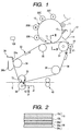
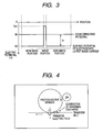
- Fig. 1 is a typical view showing an image forming apparatus according to a first embodiment of the invention and Fig. 2 is an end view showing an enlarged portion taken along a II - II line in Fig. 1.
- a charging roller 11 serving as charging unit, a developing roller 20 (Y, M, C and K) serving as developing unit, an intermediate transfer member 30 and a cleaning unit 12 are provided in the direction of a rotation around an image carrier 10.
- the image carrier 10 has a cylindrical conductive base material 10a (see Fig. 2) and a photosensitive layer 10b formed on a surface thereof.
- the charging roller 11 abuts on the outer peripheral surface of the image carrier 10 to uniformly charge the outer peripheral surface.
- a selective light L is exposed corresponding to desirable image information by an exposing unit over the outer peripheral surface of the image carrier 10 charged uniformly so that an electrostatic latent image is formed on the image carrier 10 by the exposed light L.
- the developing roller 20Y for yellow, the developing roller 20C for cyan, the developing roller 20M for magenta and the developing roller 20K for black are provided as the developing roller 20.
- These developing rollers 20Y, 20C, 20M and 20K can selectively abut on the image carrier 10.
- any of yellow, cyan, magenta and black toners is given to the surface of the image carrier 10 so that the electrostatic latent image on the image carrier 10 is developed.
- the toner image thus developed is transferred onto an intermediate transfer belt 36 of the intermediate transfer device 30.
- a patch sensor PS serving as a toner density detecting unit is provided opposite to the surface of the intermediate transfer belt 36 in the vicinal position of the primary transfer region.
- the cleaning unit 12 includes a cleaner blade 13 for scraping off a toner remaining on and stuck to the outer peripheral surface of the image carrier 10 after the transfer and a receiving portion 14 for receiving the toner thus scraped off.
- the intermediate transfer device 30 has a driving roller 31, four driven rollers 32, 33, 34 and 35, and the non-end intermediate transfer belt 36 stretched over each of the rollers.
- the intermediate transfer belt 36 is constituted by a multilayer structure having a conductive layer 36a and a resistive layer 36b formed on the conductive layer 36a and pressed in contact with the image carrier 10.
- the conductive layer 36a is formed on an insulating base member 36c formed of a synthetic resin, and a primary transfer voltage Vt1 is applied to the conductive layer 36a through an electrode roller 37.
- the resistive layer 36b is removed like a band in the side edge portion of the belt 36 so that the conductive layer 36a is exposed like the band and the electrode roller 37 comes in contact with the exposed portion.
- a toner image on the image carrier 10 is transferred onto the intermediate transfer belt 36 in a primary transfer portion T1
- a toner image transferred onto the intermediate transfer belt 36 is transferred by applying a secondary transfer voltage V2 to a recording medium S such as a paper supplied between the intermediate transfer belt 36 and a secondary transfer roller 38 in a secondary transfer portion T2.
- the recording medium S is fed from a paper feed device which is not shown and is supplied to the secondary transfer portion T2 in a predetermined timing by a gate roller pair 40.
- a cleaner blade 39a of a belt cleaner 39 abuts on the intermediate transfer belt 36 to remove the toner remaining on the intermediate transfer belt 36 after a secondary transfer and to drop the toner into a receiving portion 39b.
- the intermediate transfer belt 36 stretched over the rollers and pressed in contact with the image carrier 10 between rollers is constituted by the multilayer structure having the conductive layer 36a and the resistive layer 36b formed on the conductive layer 36a and pressed in contact with the image carrier 10.
- the intermediate transfer belt 36 is constituted by the multilayer structure having the conductive layer 36a and the resistive layer 36b formed on the conductive layer 36a and pressed in contact with the photosensitive member 10.
- the influence of the unevenness of the surface resistance of the intermediate transfer belt 36 is small and a transfer unevenness is generated with difficulty.
- the electric potential on the back side of the resistive layer 36b of the intermediate transfer belt 36 becomes uniform over the whole region of the pressure contact portion (that is, the primary transfer portion) T1 of the image carrier 10 with the intermediate transfer belt 36. Consequently, it is possible to carry out a transfer at a minimum voltage.
- the outer surface of the image carrier 10 is charged to have a negative surface potential Vo by the charging roller 11.
- a part of electric charges in the irradiated portion is neutralized so that the surface potential is changed to Von.
- scanning and exposure are carried out over the image carrier 10 while the light exposure L is turned ON/OFF corresponding to an image signal.
- an electrostatic latent image corresponding to the image signal is formed on the image carrier 10.
- the electrostatic latent image thus formed is delivered to a developing position which is opposed to the developing roller 20 constituting the developing unit by the rotation of the image carrier 10.
- a toner charged to be negative is carried on the developing roller 20, and furthermore, a developing bias potential Vb to promote the toner to be stuck to the image portion of the image carrier 10 is applied thereto.
- the developing bias potential Vb is set to have a value between the non-image portion potential Vd and the image portion potential Von.
- the surface of the image carrier 10 has a lower electric potential than the developing roller 20 in a non-image portion, while the surface of the image carrier 10 has a higher electric potential than the developing roller 20 in an image portion.
- any of the negative charged toners carried on the developing roller 20 which is placed in an opposed position to the image portion is moved to the image carrier 10 side by an electrostatic force, while a force in a drawing direction toward the developing roller 20 side acts on the toner placed in an opposed position to the non-image portion.
- the toner is stuck to only the image portion so that the electrostatic latent image on the image carrier 10 is revealed with the toner.
- a relative electric potential relationship between the developing bias potential Vb and the non-image portion potential Vd greatly influences the quality of a toner image which is obtained and the amount of toner scattering into the apparatus in addition to the shade of an image.
- the developing bias potential Vb is approximated to the level of the non-image portion potential Vd to reduce the reverse contrast potential Vr.
- the potential difference from the developing roller 20 is reduced in the non-image portion of the image carrier 10. Therefore, an action for returning an extra toner to the developing roller 20 side is reduced.
- the amount of the toner liberated from the developing roller 20 and scattering into the apparatus is increased.
- the developing bias potential Vb is exactly maintained and the absolute value of the non-image portion potential Vd is increased to raise the reverse contrast potential Vr
- the amount of the toner scattering into the apparatus can be decreased and a force for repelling a negative charged toner by a negative charge held in the non-image portion of the image carrier 10 is increased.
- the toner is stuck, with difficulty, to an image portion in a narrow region interposed between the non-image portions, particularly, in an electrostatic latent image.
- the quality of a low density image having a comparatively low area ratio of a dot is deteriorated, for example, an isolated dot or a fine line is blurred or the uniformity of a line width is deteriorated.
- the reverse contrast potential Vr in order to suppress the toner scattering, while there is a contradicting demand for reducing the reverse contrast potential Vr in order to maintain the quality of an image, for example, the uniformity of a fine line.
- a parameter for example, the developing bias potential Vb in such a manner that the reverse contrast potential Vr always has a proper value.
- a control unit for holding the potential difference between the developing bias potential Vb and the non-image portion potential Vd on the image carrier 10, that is, the reverse contrast potential Vr to be constant, and furthermore, forming a halftone toner image as a patch image while setting and changing an image density control factor to influence the image density of a toner image in a multistage, optimizing the image density control factor based on the result of the detection of the image density of the patch image which is obtained by the density detecting unit, thereby controlling the image density of a toner image formed by the developing unit.
- the developing bias potential Vb is changed and set in a multistage to form the patch image in a state in which the absolute values of an exposure energy and a non-image portion potential are fixed to be maximum values within a variable range thereof.
- the reverse contrast potential Vr
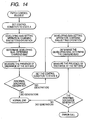
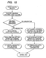
- Fig. 5A shows a relationship between electric potentials in a normal mode, and a primary transfer is carried out while the reverse contrast potential Vr to be the difference between the developing bias potential Vb and the non-image portion potential Vd is held to be constant.
- the potential difference Vdt
- Fig. 5B shows the relationship between the electric potentials in a state in which the abnormal discharge is generated.
- the thickness of the photosensitive layer of the image carrier is decreased and the threshold of the generation of the abnormal discharge is reduced, and furthermore, a developing property (a flying property) is deteriorated after a large number of sheets are printed. Consequently, it is necessary to set the developing bias potential Vb to be high.
- the developing bias potential Vb is set to be high so that it is necessary to hold the reverse bias potential Vr to be constant.
- the control unit of the image forming apparatus has an abnormal discharge countermeasure mode.
- the reverse contrast potential Vr is the difference between the developing bias potential Vb and the non-image portion potential Vd.
- the reverse contrast potential Vr is held to be constant and a toner image of high picture quality is stably formed, and furthermore, the toner scattering into the apparatus is also suppressed effectively.
- a control is carried out in such a direction that the primary transfer bias potential Vt1 is exactly maintained and the reverse contrast potential Vr is decreased in order to cause the potential difference Vdt between the non-image portion potential Vd and the primary transfer bias potential Vt1 to be equal to or smaller than the threshold Vth of the generation of the abnormal discharge.
- Fig. 7 shows an embodiment in which the control is carried out to fix the non-image portion potential Vd and the potential difference Vdt between the non-image portion potential Vd and the primary transfer bias potential Vt1 is set to be equal to or smaller than the threshold Vth of the generation of the abnormal discharge in the control region ⁇ Vb2 in which the reverse contrast potential Vr in the abnormal discharge countermeasure mode is decreased.
- Fig. 8 shows a relationship between electric potentials in the control region ⁇ Vb2 for decreasing the reverse contrast potential Vr in the abnormal discharge countermeasure mode.
- a control is carried out to hold the primary transfer bias potential Vt1 to be constant, and furthermore, to hold the non-image portion potential Vd to be constant. Even if the developing bias potential Vb is set to be high in order to hold a developing property, the reverse contrast potential Vr is decreased.
- the potential difference Vdt between the non-image portion potential Vd and the primary transfer bias potential Vt1 can be held to be equal to or smaller than the threshold Vth of the generation of the abnormal discharge. Consequently, it is possible to prevent an abnormal image from being generated due to an abnormal discharge.
- the normal mode and the abnormal discharge countermeasure mode can be switched by the operation of a control panel provided in the apparatus body. Consequently, the control region ⁇ Vb2 for decreasing the reverse contrast potential Vr is held only when the abnormal image is generated due to the abnormal discharge. Therefore, it is possible to minimize the influence of a reduction in the reverse contrast potential Vr.
- the apparatus body may be provided with sensors 100 for detecting information about a lifetime such as the number of used sheets and information about an environment such as a temperature and humidity and an air pressure which are the fluctuation factors of the threshold Vth of the generation of the abnormal discharge with the potential difference Vdt between the non-image portion potential Vd and the primary transfer bias potential Vt1, and thus, the normal mode and the abnormal discharge countermeasure mode may be switched based on data transmitted from each of the sensors 100.
- Table 1 shows the result of an experiment in the image forming apparatus according to the first embodiment of the invention.
- NG example Vb (Development)
- Vr (
- Vt1 (Primary transfer Vdt (
- the potential difference Vdt between the non-image portion potential Vd and the primary transfer bias potential Vt1 can be caused to be equal to or smaller than the threshold Vth of the generation of the abnormal discharge and an abnormal image can be prevented from being generated due to an abnormal discharge by setting the control region ⁇ Vb2 for decreasing the reverse contrast potential Vr in the region for generating the abnormal image due to the abnormal discharge in the abnormal discharge countermeasure mode.
- the image forming apparatus includes a control unit for holding the potential difference between the developing bias potential Vb and the non-image portion potential Vd on the image carrier 10, that is, the reverse contrast potential Vr to be constant while maintaining the primary transfer potential to be constant in the normal mode, and furthermore, forming a halftone toner image as a patch image while setting and changing an image density control factor to influence the image density of a toner image in a multistage, and optimizing the image density control factor based on the result of the detection of the image density of the patch image which is obtained by the density detecting unit, thereby controlling the image density of a toner image formed by the developing unit.
- the developing bias potential Vb is changed and set in a multistage to form the patch image in a state in which the absolute values of an exposure energy and a non-image portion potential are fixed to be maximum values within a variable range thereof.
- the reverse contrast potential Vr
- the control unit of the image forming apparatus has an abnormal discharge countermeasure mode.
- the primary transfer bias potential Vt1 is held to be constant and is used in a state in which the primary transfer efficiency is high so that it is possible to carry out a primary transfer in a small amount of a waste toner.
- a control is carried out in such a direction as to decrease the primary transfer bias potential Vt1 in order to cause the potential difference Vdt between the non-image portion potential Vd and the primary transfer bias potential Vt1 to be equal to or smaller than the threshold Vth of the generation of the abnormal discharge.
- the control is carried out to cause the potential difference Vdt between the non-image portion potential Vd and the primary transfer bias potential Vt1 to be equal to or smaller than the threshold Vth of the generation of the abnormal discharge so that the abnormal image can be prevented from being generated due to the abnormal discharge.
- Fig. 10 shows a relationship between electric potentials in the control region ⁇ Vb2 for decreasing the primary transfer bias potential Vt1 in the abnormal discharge countermeasure mode. It is possible to control the primary transfer bias potential Vt1 to be decreased while controlling the reverse contrast potential Vr to be constant, thereby holding the potential difference Vdt between the non-image portion potential Vd and the primary transfer bias potential Vt1 to be equal to or smaller than the threshold Vth of the generation of the abnormal discharge. Consequently, it is possible to prevent the abnormal image from being generated due to the abnormal discharge.
- the normal mode and the abnormal discharge countermeasure mode can be switched by the operation of a control panel provided in the apparatus body. Only when the abnormal image is generated due to the abnormal discharge, consequently, the switching to the control region ⁇ Vb2 for decreasing the primary transfer bias potential Vt1 is carried out. Therefore, it is possible to minimize the influence of a reduction in the primary transfer efficiency due to the decrease in the primary transfer bias potential Vt1.
- the apparatus body may be provided with sensors for detecting information about a lifetime such as the number of used sheets and information about an environment such as a temperature and humidity and an air pressure which are the fluctuation factors of the threshold Vth of the generation of the abnormal discharge with the potential difference Vdt between the non-image portion potential Vd and the primary transfer bias potential Vt1, and thus, the normal mode and the abnormal discharge countermeasure mode may be switched based on data transmitted from each of the sensors.
- Table 2 shows the result of an experiment in the image forming apparatus according to the second embodiment of the invention.
- NG example Vb (Development)
- Vr (
- Vt1 (Primary transfer Vdt (
- a discharge threshold is 1000
- Vb Development
- Vd Non-image portion potential
- Vt1 Primary transfer
- Presence of abnormal discharge (No, Yes) Fine line density Transfer efficiency -100 -500 -400 300 800 No Normal Normal -150 -550 -400 300 850 No Normal Normal -200 -600 -400 300 900 No Normal Normal -250 -650 -400 300 950 No Normal Normal -300 -700 -400 300 1000 No Normal Normal -350 -700 -400 250 1000 No Normal Slightly reduced -400 -800 -400 200 1000 No Normal Slightly reduced In the case in which a discharge threshold is 1000 V
- the potential difference Vdt between the non-image portion potential Vd and the primary transfer bias potential Vt1 can be caused to be equal to or smaller than the threshold Vth of the generation of the abnormal discharge and an abnormal image can be prevented from being generated due to an abnormal discharge by setting the control region ⁇ Vb2 for decreasing the primary transfer bias potential Vt1 in the region in which the abnormal image is generated due to the abnormal discharge in the abnormal discharge countermeasure mode.
- the image forming apparatus includes a control unit for holding the potential difference between the developing bias potential Vb and the non-image portion potential Vd on the image carrier 10, that is, the reverse contrast potential Vr to be constant, and furthermore, forming a halftone toner image as a patch image while setting and changing an image density control factor to influence the image density of a toner image in a multistage, and optimizing the image density control factor based on the result of the detection of the image density of the patch image which is obtained by the density detecting unit, thereby controlling the image density of a toner image formed by the developing unit.
- the developing bias potential Vb is changed and set in a multistage to form the patch image in a state in which the absolute values of an exposure energy and a non-image portion potential are fixed to be maximum values within a variable range thereof.
- the reverse contrast potential Vr
- the potential difference between the developing bias potential Vb and the non-image portion potential Vd, that is, the reverse contrast potential Vr is held to be constant when the halftone toner image is to be formed as the patch image.
- a toner density detecting unit is provided opposite to the surface of the image carrier or the intermediate transfer belt, thereby measuring the density of a predetermined patch image formed on the image carrier or the intermediate transfer belt.
- the density of the predetermined patch image for example, the toner image of an image having a low density (a dot area ratio of 10%) after an image having a high density (a dot area ratio of 100%) is compared with that of an image having a low density (a dot area ratio of 10%) after an image having a medium density (a dot area ratio of 30%) and an abnormal image is decided to be generated due to an abnormal discharge when a predetermined difference or more is detected from both of them.
- the reason why the patch image having the low density after the high density is compared with the patch image having the low density after the medium density is that the probability of the abnormal discharge in a toner image having a low density is higher than that in a toner image having a high density and a difference in the density can be measured more easily with the low density.
- the control unit of the image forming apparatus has an abnormal discharge countermeasure mode.
- the reverse contrast potential Vr is held to be constant and a toner image of high picture quality is stably formed, and furthermore, the toner scattering into the apparatus is also suppressed effectively.
- a control is carried out in such a direction that the primary transfer bias potential Vt1 is exactly maintained and the reverse contrast potential Vr is decreased in order to cause the potential difference Vdt between the non-image portion potential Vd and the primary transfer bias potential Vt1 to be equal to or smaller than the threshold Vth of the generation of the abnormal discharge in the control region ⁇ Vb2.
- Fig. 12 shows an embodiment in which the control is carried out to fix the non-image portion potential Vd and the potential difference Vdt between the non-image portion potential Vd and the primary transfer bias potential Vt1 is set to be equal to or smaller than the threshold Vth of the generation of the abnormal discharge in the control region ⁇ Vb2 in which the reverse contrast potential Vr in the abnormal discharge countermeasure mode is decreased.
- Fig. 13 shows a relationship between electric potentials in the control region ⁇ Vb2 for decreasing the reverse contrast potential Vr in the abnormal discharge countermeasure mode.
- a control is carried out to hold the primary transfer bias potential Vt1 to be constant, and furthermore, to hold the non-image portion potential Vd to be constant. Even if the developing bias potential Vb is set to be high in order to hold a developing property, the reverse contrast potential Vr is decreased.
- the potential difference Vdt between the non-image portion potential Vd and the primary transfer bias potential Vt1 can be held to be equal to or smaller than the threshold Vth of the generation of the abnormal discharge. Consequently, it is possible to prevent an abnormal image from being generated due to an abnormal discharge.
- the normal mode and the abnormal discharge countermeasure mode can be switched by the operation of a control panel provided in the apparatus body in addition to the operation of the toner density detecting unit through the patch image. Consequently, the switching to the control region ⁇ Vb2 for decreasing the reverse contrast potential Vr is carried out only when the abnormal image is generated due to the abnormal discharge. Therefore, it is possible to minimize the influence of a reduction in the reverse contrast potential Vr.
- the apparatus body may be provided with sensors for detecting information about a lifetime such as the number of used sheets and information about an environment such as a temperature and humidity and an air pressure which are the fluctuation factors of the threshold Vth of the generation of the abnormal discharge with the potential difference Vdt between the non-image portion potential Vd and the primary transfer bias potential Vt1, and thus, it is also possible to add the function of switching the normal mode and the abnormal discharge countermeasure mode based on data sent from each sensor.
- Fig. 14 is a flowchart according to an embodiment of a process for switching the normal mode and the abnormal discharge countermeasure mode depending on the generation of an abnormal image due to an abnormal discharge according to the invention.
- a patch control request is given for the presence of the abnormal discharge and, first of all, a state A is set as a control condition (the reverse contrast potential Vr is constant).
- a developing bias setting operation and a charging bias setting operation corresponding to the state A are carried out, and a developing bias and a charging bias corresponding to the state A are determined and a patch image is formed on the image carrier or the intermediate transfer belt at the biases thus set.
- the presence of the abnormal discharge is executed by detecting the density of the patch image through a patch sensor serving as a toner density detecting unit.
- a patch sensor serving as a toner density detecting unit.
- the density of a patch image having a low density after a high density is compared with that of a patch image having a low density after a medium density, and it is decided that the abnormal discharge is generated if a predetermined difference in the density or more is detected from both of them.
- a decision of "normal" is given.
- a state B is set as a control condition (the reverse contrast potential Vr is decreased) and a developing bias setting operation and a charging bias setting operation corresponding to the state B are carried out, a developing bias and a charging bias corresponding to the state B are determined, and a patch image is formed on the image carrier or the intermediate transfer belt at the biases thus set.
- the presence of the abnormal discharge is detected by the detection of a density through the patch image in the same manner as described above.
- Fig. 15 is a flowchart according to another embodiment of the process for switching the normal mode and the abnormal discharge countermeasure mode depending on the generation of an abnormal image due to an abnormal discharge according to the invention.
- a patch control request is given for checking the presence of the abnormal discharge and an image density control factor is varied in a multistage, and at the same time, a predetermined patch image is created, a toner density is detected by the toner density detecting unit, and an abnormal discharge start voltage is measured based on the toner image thus detected so that the presence of an abnormal discharge is decided.
- a state A is set as a control condition (the reverse contrast potential Vr is constant) and a developing bias setting operation and a charging bias setting operation corresponding to the state A are carried out, and a developing bias and a charging bias corresponding to the state A are determined.
- a state B is set as a control condition (the reverse contrast potential Vr is decreased) to set the upper limit of a charging bias potential. Subsequently, a developing bias setting operation and a charging bias setting operation corresponding to the state B are carried out, and a developing bias and a charging bias corresponding to the state B are determined.
- Table 3 shows the result of an experiment in the image forming apparatus according to the third embodiment of the invention.
- NG example
- Vb Development
- Vd Non-image portion potential
- Vt1 Primary transfer
- the potential difference Vdt between the non-image portion potential Vd and the primary transfer bias potential Vt1 can be caused to be equal to or smaller than the threshold Vth of the generation of the abnormal discharge and an abnormal image can be prevented from being generated due to an abnormal discharge by setting the control region ⁇ Vb2 for decreasing the reverse contrast potential Vr in the region in which the abnormal image is generated due to the abnormal discharge in the abnormal discharge countermeasure mode.
- the image forming apparatus includes a control unit for holding the potential difference between the developing bias potential Vb and the non-image portion potential Vd on the image carrier 10, that is, the reverse contrast potential Vr to be constant, and furthermore, forming a halftone toner image as a patch image while setting and changing an image density control factor to influence the image density of a toner image in a multistage, and optimizing the image density control factor based on the result of the detection of the image density of the patch image which is obtained by the density detecting unit, thereby controlling the image density of a toner image formed by the developing unit.
- the developing bias potential Vb is changed and set in a multistage to form the patch image in a state in which the absolute values of an exposure energy and a non-image portion potential are fixed to be maximum values within a variable range thereof.
- the reverse contrast potential Vr
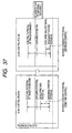
- Fig. 16 is a graph in which an axis of abscissa indicates the potential difference Vdt (V) between the non-image portion potential Vd and the primary transfer bias potential Vt1 and an axis of ordinate indicates a transfer current It1 ( ⁇ A), in which the transfer current value It1 is rapidly increased at a portion in which Vdt has a value of 1000V.
- Vdt the potential difference between the non-image portion potential Vd and the primary transfer bias potential Vt1
- ⁇ A transfer current It1
- a toner density detecting unit is provided opposite to the surface of the image carrier or the intermediate transfer belt, thereby measuring the density of a predetermined patch image formed on the image carrier or the intermediate transfer belt.
- the density of the predetermined patch image for example, the toner image of an image having a low density (a dot area ratio of 10%) after an image having a high density (a dot area ratio of 100%) is compared with that of an image having a low density (a dot area ratio of 10%) after an image having a medium density (a dot area ratio of 30%) and an abnormal image is decided to be generated due to an abnormal discharge when a predetermined difference or more is detected from both of them.
- the reason why the patch image having the low density after the high density is compared with the patch image having the low density after the medium density is that the probability of the abnormal discharge in a toner image having a low density is higher than that in a toner image having a high density and a difference in the density can be measured more easily with the low density.
- the control unit of the image forming apparatus has an abnormal discharge countermeasure mode.
- the reverse contrast potential Vr is held to be constant and a toner image of high picture quality is stably formed, and furthermore, the toner scattering into the apparatus is also suppressed effectively.
- Fig. 19 shows an embodiment in which the control is carried out to fix the non-image portion potential Vd and the potential difference Vdt between the non-image portion potential Vd and the primary transfer bias potential Vt1 is set to be equal to or smaller than the threshold Vth of the generation of the abnormal discharge in the control region ⁇ Vb2 in which the reverse contrast potential Vr in the abnormal discharge countermeasure mode is decreased.
- Fig. 20 shows a relationship between electric potentials in the control region ⁇ Vb1 for setting the reverse contrast potential in the abnormal discharge countermeasure mode to be constant and the control region ⁇ Vb2 for decreasing the reverse contrast potential Vr.
- a control for holding the primary transfer bias potential Vt1 to be constant, and furthermore, holding the non-image portion potential Vd to be constant is carried out. Even if the developing bias potential Vb is set to be high in order to hold a developing property, the reverse contrast potential Vr is decreased.
- the potential difference Vdt between the non-image portion potential Vd and the primary transfer bias potential Vt1 can be held to be equal to or smaller than the threshold Vth of the generation of the abnormal discharge. Consequently, it is possible to prevent an abnormal image from being generated due to an abnormal discharge.
- the normal mode and the abnormal discharge countermeasure mode can be switched by the operation of a control panel provided in the apparatus body in addition to the operation of the toner density detecting unit through the patch image. Consequently, the switching to the control region ⁇ Vb2 for decreasing the reverse contrast potential Vr is carried out only when the abnormal image is generated due to the abnormal discharge. Therefore, it is possible to minimize the influence of a reduction in the reverse contrast potential Vr.
- the apparatus body may be provided with sensors for detecting information about a lifetime such as the number of used sheets and information about an environment such as a temperature and humidity and an air pressure which are the fluctuation factors of the threshold Vth of the generation of the abnormal discharge with the potential difference Vdt between the non-image portion potential Vd and the primary transfer bias potential Vt1, and thus, it is also possible to add the function of switching the normal mode and the abnormal discharge countermeasure mode based on data sent from each sensor.
- Fig. 21 is a flowchart according to the fifth embodiment of a process for switching the normal mode and the abnormal discharge countermeasure mode depending on the generation of an abnormal image due to an abnormal discharge according to the invention.
- a patch control request is given for the presence of the abnormal discharge and, first of all, a.state A is set as a control condition ( ⁇ Vb1 : the reverse contrast potential Vr is constant).
- a developing bias setting operation and a charging bias setting operation corresponding to the state A are carried out, and a developing bias and a charging bias corresponding to the state A are determined and a patch image is formed on the image carrier or the intermediate transfer belt at the biases thus set.
- the presence of the abnormal discharge is checked by detecting the density of the patch image through a patch sensor to be toner density detecting unit.
- the density of a patch image having a low density after a high density is compared with that of a patch image having a low density after a medium density, and it is decided that the abnormal discharge is generated if a predetermined difference in the density or more is detected from both of them.
- a decision of "normal" is given.
- a state B is set as a control condition ( ⁇ Vb2 : the reverse contrast potential Vr is decreased) and a developing bias setting operation and a charging bias setting operation corresponding to the state B are carried out, a developing bias and a charging bias corresponding to the state B are determined, and a patch image is formed on the image carrier or the intermediate transfer belt at the biases thus set. Consequently, the presence of the abnormal discharge is detected by the detection of a density through the patch image in the same manner as described above.
- Fig. 22 is a flowchart according to the sixth embodiment of the process for switching the normal mode and the abnormal discharge countermeasure mode depending on the generation of an abnormal image due to an abnormal discharge according to the invention.
- a patch control request is given for checking the presence of the abnormal discharge and an image density control factor is varied in a multistage, and at the same time, a predetermined patch image is created, a toner density is detected by the toner density detecting unit, and an abnormal discharge start voltage is measured based on the toner density thus detected so that the presence of an abnormal discharge is decided.
- a state A is set as a control condition ( ⁇ Vb1 : the reverse contrast potential Vr is constant) and a developing bias setting operation and a charging bias setting operation corresponding to the state A are carried out, and a developing bias and a charging bias corresponding to the state A are determined.
- a state B is set as a control condition ( ⁇ Vb2 : the reverse contrast potential Vr is decreased) to set the upper limit of a charging bias potential. Subsequently, a developing bias setting operation and a charging bias setting operation corresponding to the state B are carried out, and a developing bias and a charging bias corresponding to the state B are determined.
- Table 4 shows the result of an experiment in the image forming apparatus according to the fifth embodiment of the invention.
- NG example
- Vb Development
- Vd Non-image portion potential
- Vt1 Primary transfer
- Fine line density Amount of scattering Remark -100 -500 -400 300 800 No Normal Normal -150 -550 -400 300 850 No Normal Normal -200 -600 -400 300 900 No Normal Normal -250 -650 -400 300 950 No Normal Normal -300 -700 -400 300 1000 No Normal Normal -350 -750 -400 300 1050 Yes Normal Normal -400 -800 -400 300 1100 Yes Normal Normal
- a discharge threshold is 1000
- the potential difference Vdt between the non-image portion potential Vd and the primary transfer bias potential Vt1 can be caused to be equal to or smaller than the threshold Vth of the generation of the abnormal discharge and an abnormal image can be prevented from being generated due to an abnormal discharge by setting the control region ⁇ Vb2 for decreasing the reverse contrast potential Vr in the abnormal discharge countermeasure mode in the region in which the abnormal image is generated due to the abnormal discharge.
- Fig. 23 is a typical view showing the seventh embodiment of an image forming apparatus according to the invention and Fig. 24 is an end view showing an enlarged portion taken along a II - II line in Fig. 23.
- Fig. 25 is a partial enlarged view showing an embodiment of a corona charging unit.
- a corona charger 111 serving as a charging unit, a developing roller 20 (Y, M, C and K) serving as a developing unit, an intermediate transfer unit 30 and a cleaning unit 12 are provided in the direction of a rotation around an image carrier 10.
- the image carrier 10 has a cylindrical conductive base material 10a (see Fig. 24) and a photosensitive layer 10b formed on a surface thereof.
- the corona charger 111 includes a discharge electrode 123 in a back plate 122 to be a metal casing and a grid electrode 24 provided between the image carrier 10 and the discharge electrode 123 (see Fig. 25) and uniformly charges the outer peripheral surface of the image carrier 10.
- a selective light L is exposed corresponding to desirable image information by an exposing unit over the outer peripheral surface of the image carrier 10 charged uniformly so that an electrostatic latent image is formed on the image carrier 10 by the exposed light L.
- the identical parts and portions will be denoted by the same reference numerals, and a detailed description thereof will be omitted.
- the outer surface of the image carrier 10 provided under the corona charger 111 is charged to have a negative surface potential Vo with a grid bias potential Vg of the grid electrode 24 of the corona charger 111.
- a part of electric charges in the irradiated portion is neutralized so that the surface potential is changed to Von.
- scanning and exposure are carried out over the image carrier 10 while the light exposure L is tumed ON/OFF corresponding to an image signal.
- a relationship between Vo and the non-image portion potential Vd in the primary transfer portion is determined by a characteristic, that is, the dark decay which is peculiar to the material of the image carrier 10, and Vd is determined by the dark decay and a time required for reaching the primary transfer portion from a charging position. Accordingly, the grid bias potential Vg and the non-image portion potential Vd in the primary transfer portion have a functional relation.
- an electrostatic latent image corresponding to the image signal is formed on the image carrier 10.
- the electrostatic latent image thus formed is delivered to a developing position which is opposed to the developing roller 20 constituting the developing unit by the rotation of the image carrier 10.
- a toner charged to be negative is carried on the developing roller 20, and furthermore, a developing bias potential Vb to promote the toner to be stuck to the image portion of the image carrier 10 is applied thereto.
- the developing bias potential Vb is set to have a value between the non-image portion potential Vd and the image portion potential Von. In a developing position, accordingly, the surface of the image carrier 10 has a lower electric potential than the developing roller 20 in a non-image portion, while the surface of the image carrier 10 has a higher electric potential than the developing roller 20 in an image portion.
- any of the negative charged toners carried on the developing roller 20 which is placed in an opposed position to the image portion is moved to the image carrier 10 side by an electrostatic force, while a force in a drawing direction toward the developing roller 20 side acts on the toner placed in an opposed position to the non-image portion.
- the toner is stuck to only the image portion so that the electrostatic latent image on the image carrier 10 is revealed with the toner.
- a relative electric potential relationship between the developing bias potential Vb and the non-image portion potential Vd greatly influences the quality of a toner image which is obtained and the amount of toner scattering into the apparatus in addition to the shade of an image.
- the absolute value of the potential difference between the developing bias potential Vb and the non-image portion potential Vd will be referred to as a reverse contrast potential. More specifically, the reverse contrast potential is set to be
- the developing bias potential Vb is approximated to the level of the grid bias potential Vg having the functional relation with the non-image portion potential Vd to reduce the reverse contrast potential Vr.
- the potential difference from the developing roller 20 is reduced in the non-image portion of the image carrier 10. Therefore, an action for returning an extra toner to the developing roller 20 side is reduced.
- the amount of the toner liberated from the developing roller 20 and scattering into the apparatus is increased.
- the developing bias potential Vb is exactly maintained and the absolute value of the grid bias potential Vg having the functional relation with the non-image portion potential Vd is increased to raise the reverse contrast potential Vr
- the amount of the toner scattering into the apparatus can be decreased and a force for repelling a negative charged toner by a negative charge held in the non-image portion of the image carrier 10 is increased.
- the toner is stuck, with difficulty, to an image portion in a narrow region interposed between the non-image portions, particularly, in an electrostatic latent image.
- the quality of a low density image having a comparatively low area ratio of a dot is deteriorated, for example, an isolated dot or a fine line is blurred or the uniformity of a line width is damaged.
- the reverse contrast potential Vr in order to suppress the toner scattering, while there is a contradicting demand for reducing the reverse contrast potential Vr in order to maintain the quality of an image, for example, the uniformity of a fine line.
- a parameter for example, the developing bias potential Vb in such a manner that the reverse contrast potential Vr always has a proper value.
- a control unit for holding the potential difference between the developing bias potential Vb and the grid bias potential Vg having the functional relation with the non-image portion potential Vd on the image carrier 10, that is, the reverse contrast potential Vr to be constant, and furthermore, forming a halftone toner image as a patch image while setting and changing an image density control factor to influence the image density of a toner image in a multistage, and optimizing the image density control factor based on the result of the detection of the image density of the patch image which is obtained by the density detecting unit, thereby controlling the image density of a toner image formed by the developing unit.
- the developing bias potential Vb is changed and set in a multistage to form the patch image in a state in which the absolute values of an exposure energy and a non-image portion potential are fixed to be maximum values within a variable range thereof.
- the reverse contrast potential Vr
- the potential difference between the developing bias potential Vb and the grid bias potential Vg having the functional relation with the non-image portion potential Vd, that is, the reverse contrast potential Vr is held to be constant when the halftone toner image is to be formed as the patch image. Therefore, it is possible to form such a patch image on the condition that the very small dot and the fine line to be used for obtaining a halftone have an excellent reproducibility. Consequently, it is possible to carry out the processing of optimizing the image density control factor with high precision based on the image density of the patch image. As a result, it is possible to stably form a toner image of high picture quality.
- Fig. 28A shows a relationship between electric potentials in a normal mode, and a primary transfer is carried out while the reverse contrast potential Vr to be the difference between the developing bias potential Vb and the non-image portion potential Vd is held to be constant.
- the potential difference Vdt
- Fig. 28B shows the relationship between the electric potentials in a state in which the abnormal discharge is generated.
- the thickness of the photosensitive layer of the image carrier is decreased and the threshold of the generation of the abnormal discharge is reduced, and furthermore, a developing property (a flying property) is deteriorated after a large number of sheets are printed. Consequently, it is necessary to set the developing bias potential Vb to be high.
- the developing bias potential Vb is set to be high so that it is necessary to hold the reverse bias potential Vr to be constant.
- the control unit of the image forming apparatus has an abnormal discharge countermeasure mode.
- the abnormal discharge countermeasure mode there are set a control region ⁇ Vb1 for holding the reverse contrast potential Vr to be the difference between the developing bias potential Vb and the grid bias potential Vg having the functional relation with the non-image portion potential Vd to be constant and a control region ⁇ Vb2 for decreasing the reverse contrast potential Vr to be the difference between the developing bias potential Vb and the grid bias potential Vg having the functional relation with the non-image portion potential Vd as shown in Fig.
- a control is carried out in such a direction that the primary transfer bias potential Vt1 is exactly maintained and the reverse contrast potential Vr is decreased in order to cause the potential difference Vdt between the non-image portion potential Vd and the primary transfer bias potential Vt1 to be equal to or smaller than the threshold Vth of the generation of the abnormal discharge.
- the control is carried out to cause the grid bias potential Vg having the functional relation with the non-image portion potential Vd to be equal to or smaller than the threshold Vth of the generation of the abnormal discharge so that the abnormal image can be prevented from being generated due to the abnormal discharge.
- Figs. 30A and 30B show states brought at the early stage of the use of the apparatus in the two control regions ⁇ Vb1 and ⁇ Vb2 and after the endurance of the apparatus in the abnormal discharge countermeasure mode.
- the grid bias potential Vg is equal to the non-image portion potential Vd at the early stage of the use of the apparatus in Fig. 30A
- the thickness of the photosensitive layer of the image carrier is decreased, an abnormal discharge start voltage is dropped and
- Fig. 31 shows a relationship between electric potentials in the two control regions ⁇ Vb1 and ⁇ Vb2 in the abnormal discharge countermeasure mode.
- the primary transfer bias potential Vt1 is maintained to be constant, and furthermore, the grid bias potential Vg having the functional relation with the non-image portion potential Vd is controlled. Even if the developing bias potential Vb is set to be high, the reverse contrast potential Vr is decreased.
- the potential difference Vdt between the non-image portion potential Vd and the primary transfer bias potential Vt1 can be held to be equal to or smaller than the threshold Vth of the generation of the abnormal discharge. Consequently, it is possible to prevent an abnormal image from being generated due to an abnormal discharge.
- the normal mode and the abnormal discharge countermeasure mode can be switched by the operation of a control panel provided in the apparatus body. Consequently, the control region ⁇ Vb2 for decreasing the reverse contrast potential Vr is held only when the abnormal image is generated due to the abnormal discharge. Therefore, it is possible to minimize the influence of a reduction in the reverse contrast potential Vr.
- the apparatus body may be provided with sensors for detecting information about a lifetime such as the number of used sheets and information about an environment such as a temperature and humidity and an air pressure which are the fluctuation factors of the threshold Vth of the generation of the abnormal discharge with the potential difference Vdt between the non-image portion potential Vd and the primary transfer bias potential Vt1, and thus, the normal mode and the abnormal discharge countermeasure mode may be switched based on data transmitted from each of the sensors.
- a transfer current flows in a large amount when the abnormal discharge is generated in the primary transfer portion of the intermediate transfer belt 36 having the multilayer structure including the conductive layer and the image carrier 10.
- Table 5 shows the result of an experiment in the image forming apparatus according to the seventh embodiment of the invention.
- ) Vt1 (Primary transfer) Vdt ( lVd-Vt1
- the potential difference Vdt between the non-image portion potential Vd and the primary transfer bias potential Vt1 can be caused to be equal to or smaller than the threshold Vth of the generation of the abnormal discharge and an abnormal image can be prevented from being generated due to an abnormal discharge by setting the control region ⁇ Vb2 for decreasing the reverse contrast potential Vr in the abnormal discharge countermeasure mode in the region in which the abnormal image is generated due to the abnormal discharge.
- the image forming apparatus includes a control unit for holding the potential difference between the developing bias potential Vb and the grid bias potential Vg having the functional relation with the non-image portion potential Vd on the image carrier 10, that is, the reverse contrast potential Vr to be constant, and furthermore, forming a halftone toner image as a patch image while setting and changing an image density control factor to influence the image density of a toner image in a multistage, and optimizing the image density control factor based on the result of the detection of the image density of the patch image which is obtained by a density detecting unit, thereby controlling the image density of a toner image formed by the developing unit.
- the developing bias potential Vb is changed and set in a multistage to form the patch image in a state in which the absolute values of an exposure energy and a non-image portion potential are fixed to be maximum values within a variable range thereof.
- the reverse contrast potential Vr
- the potential difference between the developing bias potential Vb and the grid bias potential Vg having the functional relation with the non-image portion potential Vd, that is, the reverse contrast potential Vr is held to be constant when the halftone toner image is to be formed as the patch image. Therefore, it is possible to form such a patch image on the condition that the very small dot and the fine line to be used for obtaining a halftone have an excellent reproducibility. Consequently, it is possible to carry out the processing of optimizing the image density control factor with high precision based on the image density of the patch image. As a result, it is possible to stably form a toner image of high picture quality.
- a charge current is increased stepwise depending on the contamination of the corona charger 11 based on information about a lifetime such as the number of times of use so that the deterioration in the image is prevented, and at the same time, the lifetime of the corona charger 11 is increased.
- Fig. 32A shows a relationship between electric potentials in a normal mode, and a primary transfer is carried out while the reverse contrast potential Vr to be the difference between the developing bias potential Vb and the non-image portion potential Vd is held to be constant.
- the potential difference Vdt
- Fig. 32B shows the relationship between the electric potentials in a state in which the abnormal discharge is generated.
- the thickness of the photosensitive layer of the image carrier is decreased and the threshold of the generation of the abnormal discharge is reduced, and furthermore, a developing property (a flying property) is deteriorated after a large number of sheets are printed. Consequently, it is necessary to set the developing bias potential Vb to be high.
- the developing bias potential Vb is set to be high so that it is necessary to hold the reverse bias potential Vr to be constant.
- Figs. 33A and 33B show a change in the non-image portion potential Vd and the state of the generation of the abnormal discharge in the case in which the charge current is fixed by the corona charger 11 and the case in which the charge current is increased stepwise.
- the non-image portion potential Vd Since the non-image portion potential Vd is decreased, however, a deterioration in an image is generated.
- the charge current is increased stepwise corresponding to the number of sheets to be printed and the non-image portion potential Vd is increased stepwise as shown in Fig. 33B in order to prevent the deterioration in an image
- the potential difference Vdt
- the control unit of the image forming apparatus increases a discharge current to be applied to the discharge electrode 23 stepwise corresponding to the number of sheets to be printed in the corona charger 11 and decreases the non-image portion potential Vd to be increased with a stepwise increase in a discharge current in a dotted line as shown in Fig. 34.
- the decrease in the non-image portion potential Vd is linked with the deterioration in the image.
- the discharge time is prolonged corresponding to the decrease in the grid bias potential Vg, thereby preventing the deterioration in an image.
- the abnormal discharge countermeasure mode sets a control region ⁇ Vb1 for holding the reverse contrast potential Vr to be the difference between the developing bias potential Vb and the grid bias potential Vg having the functional relation with the non-image portion potential Vd to be constant and a control region ⁇ Vb2 for decreasing the reverse contrast potential Vr to be the difference between the developing bias potential Vb and the grid bias potential Vg having the functional relation with the non-image portion potential Vd.
- the reverse contrast potential Vr is held to be constant and a toner image of high picture quality is stably formed, and furthermore, the toner scattering into the apparatus is also suppressed effectively.
- a control is carried out in such a direction that the primary transfer bias potential Vt1 is exactly maintained and the reverse contrast potential Vr is decreased in order to cause the potential difference Vdt between the non-image portion potential Vd and the primary transfer bias potential Vt1 to be equal to or smaller than the threshold Vth of the generation of the abnormal discharge.
- the control is carried out to cause the grid bias potential Vg having the functional relation with the non-image portion potential Vd to be equal to or smaller than the threshold Vth of the generation of the abnormal discharge so that the abnormal image can be prevented from being generated due to the abnormal discharge.
- Figs. 36A and 36B show states brought at the early stage of the use of the apparatus in the two control regions ⁇ Vb1 and ⁇ Vb2 and after the endurance of the apparatus in the abnormal discharge countermeasure mode.
- the grid bias potential Vg is equal to the non-image portion potential Vd at the early stage of the use of the apparatus in Fig. 36A
- the thickness of the photosensitive layer of the image carrier is decreased, an abnormal discharge start voltage is dropped and
- Fig. 37 shows a relationship between electric potentials in the two control regions ⁇ Vb1 and ⁇ Vb2 in the abnormal discharge countermeasure mode.
- the primary transfer bias potential Vt1 is maintained to be constant, and furthermore, the grid bias potential Vg having the functional relation with the non-image portion potential Vd is controlled. Even if the developing bias potential Vb is set to be high, the reverse contrast potential Vr is decreased.
- the potential difference Vdt between the non-image portion potential Vd and the primary transfer bias potential Vt1 can be held to be equal to or smaller than the threshold Vth of the generation of the abnormal discharge. Consequently, it is possible to prevent an abnormal image from being generated due to an abnormal discharge.
- the normal mode and the abnormal discharge countermeasure mode can be switched by the operation of a control panel provided in the apparatus body. Consequently, the control region ⁇ Vb2 for decreasing the reverse contrast potential Vr is switched only when the abnormal image is generated due to the abnormal discharge. Therefore, it is possible to minimize the influence of a reduction in the reverse contrast potential Vr.
- the apparatus body may be provided with sensors for detecting information about a lifetime such as the number of used sheets and information about an environment such as a temperature and humidity and an air pressure which are the fluctuation factors of the threshold Vth of the generation of the abnormal discharge with the potential difference Vdt between the non-image portion potential Vd and the primary transfer bias potential Vt1, and thus, the normal mode and the abnormal discharge countermeasure mode may be switched based on data transmitted from each of the sensors.
- a transfer current flows in a large amount when the abnormal discharge is generated in the primary transfer portion of the intermediate transfer belt 36 having the multilayer structure including the conductive layer and the image carrier 10.
Landscapes
- Physics & Mathematics (AREA)
- General Physics & Mathematics (AREA)
- Engineering & Computer Science (AREA)
- Microelectronics & Electronic Packaging (AREA)
- Electrostatic Charge, Transfer And Separation In Electrography (AREA)
- Control Or Security For Electrophotography (AREA)
Applications Claiming Priority (6)
| Application Number | Priority Date | Filing Date | Title |
|---|---|---|---|
| JP2004225704A JP2006047491A (ja) | 2004-08-02 | 2004-08-02 | 画像形成装置および画像形成方法 |
| JP2004225703A JP2006047490A (ja) | 2004-08-02 | 2004-08-02 | 画像形成装置および画像形成方法 |
| JP2004225702A JP2006047489A (ja) | 2004-08-02 | 2004-08-02 | 画像形成装置および画像形成方法 |
| JP2004225700A JP2006047487A (ja) | 2004-08-02 | 2004-08-02 | 画像形成装置および画像形成方法 |
| JP2004225699A JP2006047486A (ja) | 2004-08-02 | 2004-08-02 | 画像形成装置および画像形成方法 |
| JP2004225701A JP2006047488A (ja) | 2004-08-02 | 2004-08-02 | 画像形成装置および画像形成方法 |
Publications (2)
| Publication Number | Publication Date |
|---|---|
| EP1624348A2 true EP1624348A2 (de) | 2006-02-08 |
| EP1624348A3 EP1624348A3 (de) | 2006-10-04 |
Family
ID=35159929
Family Applications (1)
| Application Number | Title | Priority Date | Filing Date |
|---|---|---|---|
| EP05016670A Withdrawn EP1624348A3 (de) | 2004-08-02 | 2005-08-01 | Bilderzeugungsvorrichtung und -verfahren |
Country Status (2)
| Country | Link |
|---|---|
| US (1) | US7409171B2 (de) |
| EP (1) | EP1624348A3 (de) |
Families Citing this family (10)
| Publication number | Priority date | Publication date | Assignee | Title |
|---|---|---|---|---|
| EP1089542A3 (de) * | 1999-09-30 | 2004-03-17 | Canon Kabushiki Kaisha | Bilderzeugungsgerät und Verfahren |
| JP2007199425A (ja) * | 2006-01-26 | 2007-08-09 | Seiko Epson Corp | 画像形成装置、及び、画像形成システム |
| JP4757107B2 (ja) * | 2006-06-21 | 2011-08-24 | キヤノン株式会社 | 画像形成装置 |
| JP2008185863A (ja) * | 2007-01-31 | 2008-08-14 | Brother Ind Ltd | 画像形成装置 |
| JP5375366B2 (ja) * | 2009-06-25 | 2013-12-25 | 富士ゼロックス株式会社 | 画像形成装置 |
| JP5862203B2 (ja) | 2011-10-28 | 2016-02-16 | ブラザー工業株式会社 | 画像形成装置 |
| JP6015015B2 (ja) | 2012-01-31 | 2016-10-26 | ブラザー工業株式会社 | 画像形成装置 |
| JP6118674B2 (ja) * | 2013-07-19 | 2017-04-19 | 株式会社沖データ | 画像形成装置 |
| JP2015022214A (ja) | 2013-07-22 | 2015-02-02 | ブラザー工業株式会社 | 画像形成装置 |
| JP2018155906A (ja) * | 2017-03-17 | 2018-10-04 | 株式会社リコー | 画像形成装置 |
Family Cites Families (25)
| Publication number | Priority date | Publication date | Assignee | Title |
|---|---|---|---|---|
| JPS54156546A (en) | 1978-05-31 | 1979-12-10 | Olympus Optical Co Ltd | Corona charger |
| JPH0721671B2 (ja) | 1985-09-10 | 1995-03-08 | キヤノン株式会社 | 画像形成装置 |
| JPH0580648A (ja) * | 1991-09-20 | 1993-04-02 | Toshiba Corp | 画像形成方法 |
| JPH0689054A (ja) * | 1992-04-30 | 1994-03-29 | Canon Inc | 潜像形成条件を自動的に設定する制御手段を有する画像形成装置 |
| JPH07160098A (ja) * | 1993-12-10 | 1995-06-23 | Mita Ind Co Ltd | 画像形成装置 |
| JP3228642B2 (ja) | 1994-07-14 | 2001-11-12 | 株式会社東芝 | 画像形成装置 |
| JP3454450B2 (ja) | 1995-06-21 | 2003-10-06 | 株式会社リコー | 画像形成装置 |
| JP3299879B2 (ja) | 1996-02-19 | 2002-07-08 | シャープ株式会社 | 画像形成装置 |
| US5887218A (en) * | 1996-06-10 | 1999-03-23 | Ricoh Co., Ltd. | Color image forming apparatus having toner and transfer sheet bearing members and image forming method thereof |
| JP2901560B2 (ja) * | 1996-12-24 | 1999-06-07 | 新潟日本電気株式会社 | カラー画像形成装置 |
| JP3792902B2 (ja) | 1997-08-04 | 2006-07-05 | キヤノン株式会社 | 画像形成装置 |
| JPH11153910A (ja) | 1997-11-20 | 1999-06-08 | Seiko Epson Corp | 画像形成装置 |
| JPH11231583A (ja) | 1998-02-12 | 1999-08-27 | Sharp Corp | 画像形成装置 |
| US6421508B2 (en) | 1998-08-31 | 2002-07-16 | Canon Kabushiki Kaisha | System for preventing retransfer of a toner image between an intermediate transfer member and an image bearing member |
| JP3466968B2 (ja) | 1998-08-31 | 2003-11-17 | キヤノン株式会社 | 画像形成装置 |
| JP3684089B2 (ja) | 1998-10-28 | 2005-08-17 | キヤノン株式会社 | 画像形成装置 |
| JP2002357939A (ja) | 2001-05-31 | 2002-12-13 | Ricoh Co Ltd | 画像形成方法および画像形成装置 |
| JP2003122095A (ja) | 2001-10-09 | 2003-04-25 | Samsung Electronics Co Ltd | 電子写真プリンタ |
| JP2003215862A (ja) | 2002-01-21 | 2003-07-30 | Seiko Epson Corp | 画像形成装置および画像形成方法 |
| JP4165075B2 (ja) * | 2002-01-21 | 2008-10-15 | セイコーエプソン株式会社 | 画像形成装置および画像形成方法 |
| JP4235399B2 (ja) | 2002-05-08 | 2009-03-11 | キヤノン株式会社 | 画像形成装置 |
| JP2003337479A (ja) | 2002-05-20 | 2003-11-28 | Ricoh Co Ltd | 画像形成装置 |
| JP4246463B2 (ja) | 2002-09-19 | 2009-04-02 | 株式会社リコー | 転写方法と転写装置及び画像形成方法と画像形成装置 |
| JP4027287B2 (ja) * | 2002-09-30 | 2007-12-26 | キヤノン株式会社 | 画像形成装置 |
| JP2004177437A (ja) | 2002-11-22 | 2004-06-24 | Canon Inc | 画像形成装置 |
-
2005
- 2005-08-01 EP EP05016670A patent/EP1624348A3/de not_active Withdrawn
- 2005-08-01 US US11/195,352 patent/US7409171B2/en not_active Expired - Fee Related
Also Published As
| Publication number | Publication date |
|---|---|
| US20060024074A1 (en) | 2006-02-02 |
| US7409171B2 (en) | 2008-08-05 |
| EP1624348A3 (de) | 2006-10-04 |
Similar Documents
| Publication | Publication Date | Title |
|---|---|---|
| KR930010873B1 (ko) | 이미지 형성장치 | |
| US6173148B1 (en) | Image forming apparatus with a transfer member having an inherent volume resistance less than that of an inner layer of a transport support element | |
| EP0646850A2 (de) | Bildtransfervorrichtung für ein Bilderzeugungsgerät | |
| CN112147867B (zh) | 图像形成装置 | |
| US20110044710A1 (en) | Image forming apparatus | |
| CN110824868B (zh) | 图像形成装置 | |
| EP1624348A2 (de) | Bilderzeugungsvorrichtung und -verfahren | |
| JP2002258714A (ja) | 画像形成装置 | |
| US20070047986A1 (en) | Image forming apparatus and density adjusting method thereof | |
| US6134416A (en) | Image forming apparatus having a transfer electrode | |
| US10824105B2 (en) | Image forming apparatus having a control of transfer voltage | |
| JP4500511B2 (ja) | 画像形成装置 | |
| US20080124102A1 (en) | Image forming apparatus | |
| US7257340B2 (en) | Image forming apparatus featuring a controller for switching a first transfer bias to a second smaller transfer bias while the print material is passing through a transfer nip portion | |
| US10578991B2 (en) | Image forming apparatus having nip portion holding recording material between transfer member and image bearing member | |
| JP2004205583A (ja) | 画像形成装置 | |
| KR102247149B1 (ko) | 화상 형성 장치 | |
| US6801743B2 (en) | Image forming apparatus with transferring member having ion conductivity | |
| US12346042B2 (en) | Image forming apparatus using plural test images formed with different test voltages | |
| US7929874B2 (en) | Transfer device and image forming apparatus using the same | |
| EP2891927B1 (de) | Ladevorrichtung, Bilderzeugungseinheit und Bilderzeugungsvorrichtung und Bilderzeugungsverfahren | |
| JP2004045877A (ja) | 画像形成装置 | |
| JP2006047491A (ja) | 画像形成装置および画像形成方法 | |
| JP2004163475A (ja) | 画像形成装置 | |
| JP2003241444A (ja) | 画像形成装置 |
Legal Events
| Date | Code | Title | Description |
|---|---|---|---|
| PUAI | Public reference made under article 153(3) epc to a published international application that has entered the european phase |
Free format text: ORIGINAL CODE: 0009012 |
|
| AK | Designated contracting states |
Kind code of ref document: A2 Designated state(s): AT BE BG CH CY CZ DE DK EE ES FI FR GB GR HU IE IS IT LI LT LU LV MC NL PL PT RO SE SI SK TR |
|
| AX | Request for extension of the european patent |
Extension state: AL BA HR MK YU |
|
| PUAL | Search report despatched |
Free format text: ORIGINAL CODE: 0009013 |
|
| AK | Designated contracting states |
Kind code of ref document: A3 Designated state(s): AT BE BG CH CY CZ DE DK EE ES FI FR GB GR HU IE IS IT LI LT LU LV MC NL PL PT RO SE SI SK TR |
|
| AX | Request for extension of the european patent |
Extension state: AL BA HR MK YU |
|
| 17P | Request for examination filed |
Effective date: 20070403 |
|
| AKX | Designation fees paid |
Designated state(s): DE FR GB |
|
| 17Q | First examination report despatched |
Effective date: 20071122 |
|
| STAA | Information on the status of an ep patent application or granted ep patent |
Free format text: STATUS: THE APPLICATION IS DEEMED TO BE WITHDRAWN |
|
| 18D | Application deemed to be withdrawn |
Effective date: 20080403 |