EP1622737B1 - Verfahren zur Erzeugung einer künstlichen Patinaoxid-Schicht auf unterschiedlchen Teilen eines Schweissbrenners - Google Patents
Verfahren zur Erzeugung einer künstlichen Patinaoxid-Schicht auf unterschiedlchen Teilen eines Schweissbrenners Download PDFInfo
- Publication number
- EP1622737B1 EP1622737B1 EP04731850A EP04731850A EP1622737B1 EP 1622737 B1 EP1622737 B1 EP 1622737B1 EP 04731850 A EP04731850 A EP 04731850A EP 04731850 A EP04731850 A EP 04731850A EP 1622737 B1 EP1622737 B1 EP 1622737B1
- Authority
- EP
- European Patent Office
- Prior art keywords
- patina
- nozzle
- welding torch
- oxide layer
- gas nozzle
- Prior art date
- Legal status (The legal status is an assumption and is not a legal conclusion. Google has not performed a legal analysis and makes no representation as to the accuracy of the status listed.)
- Expired - Lifetime
Links
Images
Classifications
-
- B—PERFORMING OPERATIONS; TRANSPORTING
- B08—CLEANING
- B08B—CLEANING IN GENERAL; PREVENTION OF FOULING IN GENERAL
- B08B9/00—Cleaning hollow articles by methods or apparatus specially adapted thereto
- B08B9/02—Cleaning pipes or tubes or systems of pipes or tubes
- B08B9/027—Cleaning the internal surfaces; Removal of blockages
- B08B9/04—Cleaning the internal surfaces; Removal of blockages using cleaning devices introduced into and moved along the pipes
- B08B9/053—Cleaning the internal surfaces; Removal of blockages using cleaning devices introduced into and moved along the pipes moved along the pipes by a fluid, e.g. by fluid pressure or by suction
- B08B9/057—Cleaning the internal surfaces; Removal of blockages using cleaning devices introduced into and moved along the pipes moved along the pipes by a fluid, e.g. by fluid pressure or by suction the cleaning devices being entrained discrete elements, e.g. balls, grinding elements, brushes
-
- B—PERFORMING OPERATIONS; TRANSPORTING
- B08—CLEANING
- B08B—CLEANING IN GENERAL; PREVENTION OF FOULING IN GENERAL
- B08B1/00—Cleaning by methods involving the use of tools
- B08B1/30—Cleaning by methods involving the use of tools by movement of cleaning members over a surface
- B08B1/32—Cleaning by methods involving the use of tools by movement of cleaning members over a surface using rotary cleaning members
-
- B—PERFORMING OPERATIONS; TRANSPORTING
- B08—CLEANING
- B08B—CLEANING IN GENERAL; PREVENTION OF FOULING IN GENERAL
- B08B1/00—Cleaning by methods involving the use of tools
- B08B1/30—Cleaning by methods involving the use of tools by movement of cleaning members over a surface
- B08B1/32—Cleaning by methods involving the use of tools by movement of cleaning members over a surface using rotary cleaning members
- B08B1/34—Cleaning by methods involving the use of tools by movement of cleaning members over a surface using rotary cleaning members rotating about an axis parallel to the surface
-
- B—PERFORMING OPERATIONS; TRANSPORTING
- B08—CLEANING
- B08B—CLEANING IN GENERAL; PREVENTION OF FOULING IN GENERAL
- B08B9/00—Cleaning hollow articles by methods or apparatus specially adapted thereto
-
- B—PERFORMING OPERATIONS; TRANSPORTING
- B23—MACHINE TOOLS; METAL-WORKING NOT OTHERWISE PROVIDED FOR
- B23K—SOLDERING OR UNSOLDERING; WELDING; CLADDING OR PLATING BY SOLDERING OR WELDING; CUTTING BY APPLYING HEAT LOCALLY, e.g. FLAME CUTTING; WORKING BY LASER BEAM
- B23K35/00—Rods, electrodes, materials, or media, for use in soldering, welding, or cutting
- B23K35/22—Rods, electrodes, materials, or media, for use in soldering, welding, or cutting characterised by the composition or nature of the material
- B23K35/224—Anti-weld compositions; Braze stop-off compositions
-
- B—PERFORMING OPERATIONS; TRANSPORTING
- B23—MACHINE TOOLS; METAL-WORKING NOT OTHERWISE PROVIDED FOR
- B23K—SOLDERING OR UNSOLDERING; WELDING; CLADDING OR PLATING BY SOLDERING OR WELDING; CUTTING BY APPLYING HEAT LOCALLY, e.g. FLAME CUTTING; WORKING BY LASER BEAM
- B23K5/00—Gas flame welding
- B23K5/22—Auxiliary equipment, e.g. backings, guides
-
- B—PERFORMING OPERATIONS; TRANSPORTING
- B23—MACHINE TOOLS; METAL-WORKING NOT OTHERWISE PROVIDED FOR
- B23K—SOLDERING OR UNSOLDERING; WELDING; CLADDING OR PLATING BY SOLDERING OR WELDING; CUTTING BY APPLYING HEAT LOCALLY, e.g. FLAME CUTTING; WORKING BY LASER BEAM
- B23K9/00—Arc welding or cutting
- B23K9/24—Features related to electrodes
- B23K9/28—Supporting devices for electrodes
-
- B—PERFORMING OPERATIONS; TRANSPORTING
- B23—MACHINE TOOLS; METAL-WORKING NOT OTHERWISE PROVIDED FOR
- B23K—SOLDERING OR UNSOLDERING; WELDING; CLADDING OR PLATING BY SOLDERING OR WELDING; CUTTING BY APPLYING HEAT LOCALLY, e.g. FLAME CUTTING; WORKING BY LASER BEAM
- B23K9/00—Arc welding or cutting
- B23K9/32—Accessories
-
- F—MECHANICAL ENGINEERING; LIGHTING; HEATING; WEAPONS; BLASTING
- F23—COMBUSTION APPARATUS; COMBUSTION PROCESSES
- F23D—BURNERS
- F23D14/00—Burners for combustion of a gas, e.g. of a gas stored under pressure as a liquid
- F23D14/46—Details
- F23D14/48—Nozzles
- F23D14/50—Cleaning devices therefor
-
- F—MECHANICAL ENGINEERING; LIGHTING; HEATING; WEAPONS; BLASTING
- F23—COMBUSTION APPARATUS; COMBUSTION PROCESSES
- F23D—BURNERS
- F23D14/00—Burners for combustion of a gas, e.g. of a gas stored under pressure as a liquid
- F23D14/46—Details
- F23D14/48—Nozzles
- F23D14/52—Nozzles for torches; for blow-pipes
-
- A—HUMAN NECESSITIES
- A46—BRUSHWARE
- A46B—BRUSHES
- A46B2200/00—Brushes characterized by their functions, uses or applications
- A46B2200/30—Brushes for cleaning or polishing
- A46B2200/3093—Brush with abrasive properties, e.g. wire bristles
-
- A—HUMAN NECESSITIES
- A46—BRUSHWARE
- A46D—MANUFACTURE OF BRUSHES
- A46D1/00—Bristles; Selection of materials for bristles
Definitions
- the invention relates to a method for producing an artificial patina oxide layer on a gas nozzle and / or the nozzle and / or the contact tube of a welding torch, wherein these parts consist of copper or a copper alloy (see, for example U.S. Patent 5,618,456 ).
- Welding torches are contaminated during the welding process by splashes of molten metal.
- the metal splash outsides outside of the housing of the gas nozzle of the welding torch and also inside the gas nozzle and solidify there.
- the flow of the protective gas is disturbed by the gas nozzle through the deposited metal splashes, so that even atmospheric air reaches the weld and thus adversely affects the welding process.
- it can lead to short circuits due to the welding spatter.
- Welding torches are therefore cleaned at regular intervals by the splashes thereon. During the cleaning time, the welding torch is not available for welding. Therefore, it is desirable to carry out the cleaning as quickly as possible.
- an anti-spatter anti-spatter agent consisting of a solution of a glycerol ester of a C18-C20 unsaturated fatty acid in a methyl or ethyl ester of such fatty acid.
- This non-stick agent is applied to those parts of a welding torch where the adhesion of the weld spatter is to be prevented.
- a coating is applied to the gas or current nozzle of a gas-shielded welding machine, the gas or current nozzle comprising a metal coated with a protective layer containing graphite and a heat-releasing polymer and / or a heat-resistant polymer , is trained.
- a welding torch and a Stromdüse or contact tube is from the DE 201 00 126 U1 known, in which a special coating is applied.
- the welding torch has an internal Nozzle, at whose end region pointing to the welding area, a hollow current nozzle is mounted on, wherein on at least a part of the surface of the Stromdüse a metallic non-stick and reflection coating is provided.
- the coating has silver as its main component.
- the US 5 618 456 A describes a method of improving the surface properties of the tail and nozzle of a welding torch to reduce spattering. This is achieved by creating an artificial patina oxide layer on the tail and nozzle.
- the US 5 714 052 A also shows a method for producing an artificial patina oxide layer using a specific electrolytic bath.
- the US Pat. No. 3,497,401 also describes a process for making an artificial patina oxide layer on parts of copper or a copper alloy using specially formulated solutions.
- the welding torch for cleaning the welding torch, in particular the gas nozzle, the contact tube and the nozzle, there are different mechanical methods. In this case, for example, with the help of metal brushes, knives or the like. The deposits, so the spatter, removed at the welding torch. During mechanical cleaning, the components of the welding torch are damaged by the mechanical effects and, as a result, their service life is shortened.
- the device comprises an open vessel to which an ultrasonic generator is connected, wherein the ultrasonic generator generates an ultrasonic wave in a liquid.
- a rotatable tool is arranged in the vessel.
- the tool may be formed by a steel wire brush or a metal brush, wherein the bristles of the brush made of steel.
- the use of the brush presupposes that the ring or the splashes from the housing due to the ultrasonic vibrations, So the ultrasonic waves, is released, so that when brushing the ring or the splashes fall off the housing.
- the brush consists of a bristle strip arranged on a cylindrical shaft, wherein the cylindrical shaft has a concentric approach with a reduced outer diameter, which fits into the hole used to attach the gas nozzle to the welding torch.
- the shaft has a handle, so that manually by a user, the device can be inserted into the gas nozzle and the user can clean the gas nozzle or the welding torch.
- the object of the present invention is to reduce the spattering in welding torches.
- the object of the invention is achieved in that the to be provided with the patina oxide layer portion of the gas nozzle and / or the nozzle tube and / or the contact tube is immersed in a first of water and 2ml per liter of water sulfur liver existing solution and after a rinse in a second from water, 1-2g per liter of water copper sulfate and 10ml per liter of water sulfuric acid solution is immersed.
- an oxide layer of the base material is the layer with the best adhesion properties, since the layer is not applied to the surface, but by the chemical process stepwise, even at the molecular level, at the grain boundaries of the structure arises from the base material.
- the artificially produced patina layer in the case of a gas nozzle consisting of copper or, in the case of the copper parts of a welding torch is a layer which is distinguished by the presence of (OH) groups.
- This oxygen compound causes high surface tension, higher temperature resistance and decreased wetting property. Further, by this oxidation film on the copper surface, the penetration of aluminum melt into the surface pores and thereby the adhesion is prevented. By this effect, the cleaning of the parts is much easier because the spatter dissolve very easily from the patina layer. Thus, it hardly comes when cleaning the parts Surface destruction, which greatly increases the life of the parts.
- a major advantage is mainly that when using the parts with the patina layer in an aluminum welding process, a very low spatter adhesion is achieved because the aluminum with the patina layer does not form a connection and thus the weld spatter very difficult to adhere ,
- the entire gas nozzle and / or the entire nozzle and / or the entire contact tube is immersed in the solutions.
- the portion of the gas nozzle and / or nozzle block and / or the contact tube to be provided with the patina oxide layer is immersed in the first solution for a few seconds.
- the portion to be provided with the patina oxide layer is preferably immersed in the second solution until the thickness of the patina oxide layer is 50 to 200 ⁇ m.
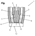
- FIG. 1 A detail, in particular an end region of a welding torch 1 assigned to the welding process, is shown in the FIGURE.
- the welding torch 1 has a gas nozzle 2, a nozzle 3 and a contact tube 4.
- the other parts of the welding torch 1 were not shown for clarity.
- the structure and the design of the illustrated parts is not limited to the embodiment shown, but it is possible that the solution according to the invention is applicable to any known from the prior art welding torch 1 and its parts.
- the gas nozzle 2 is made of copper or a copper alloy and is detachably attached to the welding torch 1.
- the contact tube 4 and the nozzle 3, which are present in each welding torch 1 in a variety of versions, are also made of copper or a copper alloy, wherein the contact tube 4 is detachably connected to the nozzle 3. A description of the operation or the task of these parts will be omitted, since this is well known in the prior art.
- spatters 5 As already mentioned in the introduction, in a welding process, spatters 5, as schematically indicated, are deposited on the gas nozzle 2, the contact tube 4 and the nozzle 3, or remain adhering to these parts. With longer welding processes, it may thus happen that the welding torch 1 is completely or partially closed with such welding spatters 5 and thus the gas flow becomes irregular or is completely interrupted and short circuits between the individual parts can also be formed. Since in conventional copper gas nozzles 2 or in the copper parts of a welding torch 1, the weld spatters 5 burn into the surface or melt on to it, it is often difficult to clean these parts, as they adhere very firmly and the detachment of spatter 5 is very difficult.
- the welding torch 1 is used in an aluminum welding, the cleaning of the copper parts, in particular of the nozzle assembly 3 and of the contact tube 4, or of the gas nozzle 2 is considerably more difficult since the aluminum welding splashes are not simply blown off during cleaning or can be peeled off.
- the aluminum spatters 5 have the property that they do not easily peel off as a whole when cleaning, but due to the softness of the material they are so smeared or triturated, ie, that the aluminum spatter 5 when cleaning with the known cleaning devices, such as For example, milling devices or brush devices with steel bristles, not as a whole can be removed, but the spatters 5 are peeled off over the cleaning devices and smear or triturate themselves.
- FIGS. 2 to 4 wherein this cleaning device, especially in aluminum welds in connection with the inventive design of the gas nozzle 2 and the welding torch. 1 , in particular of the nozzle assembly 3 and the contact tube 4, very well suited.
- those parts of the welding torch 1 made of copper or a copper alloy are specially treated, so that the adhesion of the welding spatters 5 is reduced, that is, the spatter adhesion is greatly reduced.
- the parts, in particular the gas nozzle 2, the contact tube 4 and the nozzle 3, are provided with an artificially generated patina layer 8.
- a patina layer 8 is formed by oxidation when exposing copper over a long period of time to the atmosphere, whereby the patina layer 8 forms only after about 10 years.
- the patina layer 8 consists of basic copper compounds, in particular copper carbonates and / or sulfates, which form by reaction of copper with carbon and sulfur dioxides.
- the patina layer 8 has the property that when the parts are used in an aluminum welding process, this does not bond with the aluminum, that is to say the aluminum welding spatters 5, so that the welding spatter 5 is prevented from burning or melting on the surface and thus a sealing protection is given.
- the splashing adhesion is reduced by a factor of 5 to 10, whereby the life of such parts, which are provided with the patina layer 8, is substantially increased. Also brings the formation of the patina layer 8 when cleaning the parts significant advantages, since the weld spatters 8 no longer burn into the surface of the parts or these melt, so that a simple cleaning is possible without causing the surface of the parts is destroyed ,
- the copper parts are immersed successively in two solutions.
- the first solution consists of 1 liter of water and 2 ml of sulfuric acid.
- the second solution again consists of 1 liter of water, 1 to 2g of copper sulfate and 10ml of sulfuric acid.
- the copper parts on which an artificial patina layer 8 is to be produced are now immersed in the first solution for a few seconds. Subsequently, the copper parts are rinsed and dipped in the second solution. This process is repeated several times, in particular 2 to 3 times.
- the copper part discolored and thus forms the patina layer 8, wherein the discoloration or the patina layer 8 very firmly on the base material of the copper parts, ie at the gas nozzle 2, the nozzle 3 and the contact tube 4, adheres.
- the patina layer 8 has a thickness of between 50 and 200 .mu.m.
- the patina layer 8 is provided at least at a portion of the surface of the gas nozzle 2, that is, the patina layer 8 is formed at least in that area to be protected from welding spatters 5.
- the use of such gas nozzles 2 and the welding torch 1 with the patina layer 8 is recommended for aluminum welding processes and MIG brazing. Of course, it is possible to use the welding torch 1 and the gas nozzle 2 in other welding or soldering.
Landscapes
- Engineering & Computer Science (AREA)
- Mechanical Engineering (AREA)
- Physics & Mathematics (AREA)
- Chemical & Material Sciences (AREA)
- Combustion & Propulsion (AREA)
- General Engineering & Computer Science (AREA)
- Plasma & Fusion (AREA)
- Fluid Mechanics (AREA)
- Arc Welding In General (AREA)
- Cleaning In General (AREA)
- Polishing Bodies And Polishing Tools (AREA)
Description
- Die Erfindung betrifft ein Verfahren zur Erzeugung einer künstlichen Patinaoxid-Schicht auf einer Gasdüse und/oder den Düsenstock und/oder dem Kontaktrohr eines Schweißbrenners, wobei diese Teile aus Kupfer bzw. einer Kupferlegierung bestehen (siehe z.B.
US-A-5 618 456 ). - Schweißbrenner werden während des Schweißvorganges durch Spritzer geschmolzenen Metalls verunreinigt. Dabei lagern sich die Metallspritzer außen am Gehäuse der Gasdüse des Schweißbrenners und auch innerhalb der Gasdüse ab und erstarren dort. In der Folge wird die Strömung des Schutzgases durch die Gasdüse durch die abgelagerten Metallspritzer gestört, so dass auch atmosphärische Luft an die Schweißstelle gelangt und somit den Schweißprozess negativ beeinflusst. Weiters kann es dazu führen, dass durch die Schweißspritzer Kurzschlüsse entstehen können. Für eine qualitativ hochwertige Schweißstelle ist daher ein einwandfrei funktionierender und möglichst sauberer Schweißbrenner wichtig. Schweißbrenner werden daher in regelmäßigen Abständen von den darauf befindlichen Spritzern gereinigt. Während der Reinigungszeit steht der Schweißbrenner für Schweißarbeiten nicht zur Verfügung. Daher wird angestrebt, die Reinigung möglichst rasch durchzuführen.
- Beispielsweise ist aus der
DE 44 26 303 C1 ein Antihaftmittel gegen Schweißspritzer bekannt, das aus einer Lösung eines Glycerinesters einer ungesättigten C18-C20-Fettsäure in einem Methyl- oder Ethylester einer solchen Fettsäure besteht. Dieses Antihaftmittel wird auf jene Teile eines Schweißbrenners aufgetragen, wo das Anhaften der Schweißspritzer verhindert werden soll. - Weiters ist es, gemäß
DE 195 07 472 C2 , möglich, dass eine Beschichtung auf der Gas- oder Stromdüse einer Schutzgasschweißanlage aufgebracht wird, wobei die Gas- oder Stromdüse aus einem Metall, das mit einer Schutzschicht beschichtet ist, die Graphit und ein unter Hitzeeinwirkung Kohlenstoff freisetzendes Polymer und/oder ein hitzebeständiges Polymer enthält, ausgebildet ist. - Ein Schweißbrenner und eine Stromdüse bzw. Kontaktrohr ist aus der
DE 201 00 126 U1 bekannt, bei der eine spezielle Beschichtung aufgebracht wird. Der Schweißbrenner weist einen innenliegenden Düsenstock, an dessen zum Schweißbereich weisenden Endabschnitt eine hohle Stromdüse angebracht ist, auf, wobei auf zumindest einem Teil der Oberfläche der Stromdüse eine metallische Antihaft- und Reflexions-Beschichtung vorgesehen ist. Die Beschichtung weist Silber als Hauptbestandteil auf. - Die
US 5 618 456 A beschreibt ein Verfahren zur Verbesserung der Oberflächeneigenschaften des Endstücks und der Düse eines Schweißbrenners um die Spritzerhaftigkeit zu reduzieren. Dies wird durch die Erzeugung einer künstlichen Patinaoxid-Schicht auf dem Endstück und der Düse erzielt. - Die
US 5 714 052 A zeigt ebenfalls ein Verfahren zur Herstellung einer künstlichen Patinaoxid-Schicht unter Verwendung eines bestimmten Elektrolysebads. - Die
US 3 497 401 A beschreibt ebenfalls ein Verfahren zur Herstellung einer künstlichen Patinaoxid-Schicht auf Teilen aus Kupfer oder einer Kupferlegierung unter Verwendung speziell zusammengesetzter Lösungen. - Zum Reinigen des Schweißbrenners, insbesondere der Gasdüse, dem Kontaktrohr und dem Düsenstock, existieren unterschiedliche mechanische Verfahren. Dabei werden beispielsweise mit Hilfe von Metallbürsten, Messern oder dergl. die Ablagerungen, also die Schweißspritzer, am Schweißbrenner entfernt. Bei der mechanischen Reinigung werden die Bestandteile des Schweißbrenners durch die mechanischen Einwirkungen beschädigt und in der Folge deren Lebensdauer verkürzt.
- Aus der
EP 0 765 204 B ist eine Vorrichtung zum Reinigen von Köpfen bzw. Gasdüsen von Schweißbrennern bekannt, bei der die Vorrichtung ein offenes Gefäß aufweist, mit dem ein Ultraschall-Generator verbunden ist, wobei der Ultraschall-Generator in einer Flüssigkeit eine Ultraschallwelle erzeugt. Weiters ist im Gefäß ein drehbares Werkzeug angeordnet. Dabei kann das Werkzeug durch eine Stahldrahtbürste bzw. eine Metallbürste gebildet sein, bei der die Borsten der Bürste aus Stahl bestehen. Die Verwendung der Bürste setzt allerdings voraus, dass der Ring bzw. die Spritzer vom Gehäuse durch die Ultraschall-Vibrationen, also den Ultraschallwellen, gelöst wird, so dass beim Bürsten der Ring bzw. die Spritzer vom Gehäuse abfallen. - Weiters ist aus der
DE 33 39 547 C eine Vorrichtung zum Reinigen einer Gasdüse eines Schweißbrenners bekannt, bei der die äußere Form der Bürste an die Form der zu reinigenden Innenfläche der Gasdüse angepasst ist. Dabei besteht die Bürste aus einem auf einem zylindrischen Schaft angeordneten Borstenstreifen, wobei der zylindrische Schaft einen konzentrischen Ansatz mit verringertem Außendurchmesser aufweist, der in die zur Befestigung der Gasdüse am Schweißbrenner dienende Bohrung passt. Weiters weist der Schaft einen Handstiel auf, so dass manuell von einem Benutzer aus, die Vorrichtung in die Gasdüse eingeführt werden kann und der Benutzer die Gasdüse bzw. den Schweißbrenner reinigen kann. - Grundsätzlich ist zu erwähnen, dass noch eine Vielzahl weiterer Vorrichtungen zum Reinigen von Gasdüsen eines Schweißbrenners bekannt sind, bei denen die Reinigung mit Mahlwerkzeugen, wie beispielsweise Fräswerkzeugen oder Schneidwerkzeugen, erfolgt. Hierbei wird das Werkzeug in die Gasdüse eingeführt und es werden die Spritzer durch das Werkzeug, also einem Fräser oder einem Schneidelement von der Gasdüse geschält.
- Nachteilig ist bei den aus dem Stand der Technik bekannten Systemen, dass bei derartigen mechanischen Reinigungsvorrichtungen nur dann eine erfolgreiche Reinigung der Gasdüse durchgeführt werden kann, wenn die Spritzer aus festem Material, insbesondere aus Stahl oder einer Stahllegierung bestehen, d.h., dass ein Schweißprozess zum Verbinden von Werkstücken aus Stahl oder einer Stahllegierung durchgeführt wird, wodurch die Spritzer aus diesen Materialien bestehen. Ansonst ist eine Anwendung mit den üblichen aus dem Stand der Technik bekannten Werkzeugen, nämlich einem Fräswerkzeug, einem Schneidwerkzeug oder mit Metallbürsten, nicht möglich, da bei Schweißprozessen mit weichen Materialien, wie beispielsweise Aluminium, die aus Aluminium entstehenden Spritzer, nicht einfach von der Gasdüse entfernt bzw. geschält werden können. Hier tritt nämlich der Effekt ein, dass die aus Aluminium bestehenden Spritzer sich nicht einfach im Ganzen von der Gasdüse lösen, sondern durch das Werkzeug regelrecht verrieben bzw. verschmiert werden, wodurch die Reinigungsqualität mit den bekannten Werkzeugen sehr zu wünschen übrig lässt.
- Die Aufgabe der vorliegenden Erfindung besteht darin, die Spritzerhaftigkeit bei Schweißbrennern zu reduzieren.
- Gelöst wird die erfindungsgemäße Aufgabe dadurch, dass der mit der Patinaoxid-Schicht zu versehende Teil der Gasdüse und/oder des Düsenstocks und/oder des Kontaktrohres in eine erste aus Wasser und 2ml je Liter Wasser Schwefelleber bestehende Lösung eingetaucht wird und nach einer Spülung in eine zweite aus Wasser, 1-2g je Liter Wasser Kupfersulfat und 10ml je Liter Wasser Schwefelsäure bestehende Lösung eingetaucht wird.
- Von allen Oberflächenbeschichtungsmethoden ist die Generierung einer Oxidschicht aus dem Grundwerkstoff (Patina-Schicht) jene Schicht mit den besten Haftungseigenschaften, da die Schicht nicht auf die Oberfläche aufgetragen wird, sondern durch das chemische Verfahren stufenweise, bereits auf molekularer Ebene, an den Korngrenzen des Gefüges aus dem Grundwerkstoff entsteht.
- Vorteilhaft ist hierbei, dass die künstlich erzeugte Patina-Schicht bei einer aus Kupfer bestehenden Gasdüse bzw. bei den Kupferteilen eines Schweißbrenners eine Schicht ist, welche sich durch das Vorhandensein von (OH)-Gruppen auszeichnet. Diese Sauerstoffverbindung bewirkt eine hohe Oberflächenspannung, eine höhere Temperaturbeständigkeit und eine herabgesetzte Benetzungseigenschaft. Weiters wird durch diesen Oxidationsfilm auf der Kupferoberfläche das Eindringen von Aluminiumschmelze in die Oberflächenporen und dadurch das Anhaften verhindert. Durch diesen Effekt wird auch das Reinigen der Teile wesentlich vereinfacht, da sich die Schweißspritzer sehr leicht von der Patina-Schicht lösen. Somit kommt es beim Reinigen der Teile kaum zu Oberflächenzerstörungen, wodurch die Lebensdauer der Teile sehr erhöht wird. Ein wesentlicher Vorteil liegt vor allem darin, dass bei einem Einsatz der Teile mit der Patina-Schicht in einem Aluminium-Schweißprozess eine sehr niedrige Spritzerhaftung erreicht wird, da das Aluminium mit der Patina-Schicht keine Verbindung eingeht und somit die Schweißspritzer nur sehr schwer anhaften.
- Vorteilhafterweise wird die gesamte Gasdüse und/oder der gesamte Düsenstock und/oder das gesamte Kontaktrohr in die Lösungen eingetaucht.
- Bevorzugterweise wird der mit der Patinaoxid-Schicht zu versehende Teil der Gasdüse und/oder des Düsenstocks und/oder des Kontaktrohres für einige Sekunden in die erste Lösung eingetaucht.
- Nach der Spülung wird der mit der Patinaoxid-Schicht zu versehende Teil vorzugsweise so oft in die zweite Lösung eingetaucht, bis die Dicke der Patinaoxid-Schicht 50 bis 200µm beträgt.
- Dies wird bei einem zwei- bis dreifachen Eintauchen in die zweite Lösung erzielt.
- Die vorliegende Erfindung wird anhand der beigefügten Zeichnung näher erläutert, welche einen Teilausschnitt eines Schweißbrenners geschnitten und in vereinfachter, schematischer Darstellung zeigt.
- In der Figur ist ein Ausschnitt, insbesondere ein dem Schweißprozess zugeordneter Endbereich eines Schweißbrenners 1 gezeigt. Der Schweißbrenner 1 weist eine Gasdüse 2, einen Düsenstock 3 und ein Kontaktrohr 4 auf. Die weiteren Teile des Schweißbrenners 1 wurden der Übersicht halber nicht dargestellt. Auch ist der Aufbau bzw. die Ausbildung der dargestellten Teile nicht auf das gezeigte Ausführungsbeispiel beschränkt, sondern ist es möglich, dass die erfindungsgemäße Lösung auf jeden beliebigen aus dem Stand der Technik bekannten Schweißbrenner 1 bzw. dessen Teile anwendbar ist.
- Die Gasdüse 2 besteht aus Kupfer oder einer Kupferlegierung und wird auf den Schweißbrenner 1 lösbar angebracht. Das Kontaktrohr 4 sowie der Düsenstock 3, die in jedem Schweißbrenner 1 in den unterschiedlichsten Ausführungen vorhanden sind, bestehen ebenfalls aus Kupfer bzw. einer Kupferlegierung, wobei das Kontaktrohr 4 lösbar mit dem Düsenstock 3 verbunden ist. Auf eine Beschreibung der Funktionsweise bzw. der Aufgabe dieser Teile wird verzichtet, da diese hinlänglich aus dem Stand der Technik bekannt ist.
- Wie bereits einleitend erwähnt, entstehen bei einem Schweißprozess Schweißspritzer 5, wie schematisch angedeutet, die sich an der Gasdüse 2, dem Kontaktrohr 4 und dem Düsenstock 3 ablagern bzw. an diesen Teilen haftend bleiben. Bei längeren Schweißprozessen kann es somit passieren, dass der Schweißbrenner 1 mit derartigen Schweißspritzern 5 ganz oder teilweise verschlossen wird und somit der Gasstrom unregelmäßig wird bzw. ganz unterbrochen wird und es können auch Kurzschlüsse zwischen den einzelnen Teilen gebildet werden. Da bei herkömmlichen aus Kupfer bestehenden Gasdüsen 2 bzw. bei den Kupferteilen eines Schweißbrenners 1 sich die Schweißspritzer 5 in die Oberfläche einbrennen bzw. sich an diese anschmelzen, ist es oftmals schwierig diese Teile zu reinigen, da diese sehr fest anhaften und das Ablösen der Schweißspritzer 5 sehr schwierig ist.
- Wird dann noch dazu der Schweißbrenner 1 bei einer Aluminium-Schweißung eingesetzt, so gestaltet sich das Reinigen der Kupferteile, insbesondere des Düsenstockes 3 und des Kontaktrohres 4, bzw. der Gasdüse 2 noch wesentlich schwieriger, da die Aluminium-Schweißspritzer beim Reinigen nicht einfach abgesprengt bzw. abgeschält werden können. Die Aluminium-Schweißspritzer 5 haben die Eigenschaft, dass sie sich beim Reinigen nicht einfach als Ganzes ablösen, sondern aufgrund der Weichheit des Materials diese sozusagen verschmiert bzw. verrieben werden, d.h., dass die Aluminium-Schweißspritzer 5 beim Reinigen mit den bekannten Reinigungsvorrichtungen, wie beispielsweise Fräsvorrichtungen oder Bürstenvorrichtungen mit Stahlborsten, nicht als Ganzes entfernt werden können, sondern die Schweißspritzer 5 werden über die Reinigungsvorrichtungen abgeschält und verschmieren bzw. verreiben sich dadurch.
- Speziell bei Roboteranwendungen wird eine automatisierte Reinigung des Schweißbrenners 1 vorgenommen, so dass sicher gestellt werden muss, dass die Schweißspritzer 5 möglichst vollständig entfernt werden. Hierzu ist in den Fig. 2 bis 4 ein spezielles Werkzeug 6, insbesondere eine Bürste 7, zum Reinigen des Schweißbrenners 1 näher beschrieben, wobei sich diese Reinigungsvorrichtung speziell bei Aluminium-Schweißungen in Verbindung mit der erfindungsgemäßen Ausbildung der Gasdüse 2 bzw. dem Schweißbrenner 1, insbesondere des Düsenstockes 3 und dem Kontaktrohr 4, sehr gut eignet.
- Bei der erfindungsgemäßen Lösung ist nunmehr vorgesehen, dass jene Teile des Schweißbrenners 1, die aus Kupfer oder einer Kupferlegierung bestehen, speziell behandelt werden, so dass das Haftenbleiben der Schweißspritzer 5 reduziert wird, d.h., dass die Spritzerhaftung stark reduziert wird. Hierzu werden die Teile, insbesondere die Gasdüse 2, das Kontaktrohr 4 und der Düsenstock 3, mit einer künstlich erzeugten Patina-Schicht 8 versehen.
- Grundsätzlich bildet sich eine Patina-Schicht 8 durch Oxidation, wenn man Kupfer über einen langen Zeitraum der Atmosphäre aussetzt, wobei sich die Patina-Schicht 8 erst ca. nach 10 Jahren ausbildet. Da jedoch eine derart lange Lagerzeit zum Aufbau der Patina-Schicht 8 nicht rentabel ist, werden die Teile einem künstlichen Alterungsprozess unterzogen, wodurch sich die Patina-Schicht 8 in kürzester Zeit ausbildet. Grundsätzlich besteht die Patina-Schicht 8 aus basischen Kupferverbindungen, insbesondere aus Kupfer-Carbonaten und/oder -Sulfaten, welche sich durch Reaktion von Kupfer mit Kohlen- und Schwefeldioxiden ausbilden. Die Patina-Schicht 8 hat die Eigenschaft, dass bei einer Anwendung der Teile bei einem Aluminium-Schweißprozess diese sich nicht mit dem Aluminium, also den Aluminium-Schweißspritzern 5, verbindet, so dass ein Einbrennen bzw. Anschmelzen der Schweißspritzer 5 an der Oberfläche verhindert wird und somit ein Versiegelungs-Schutz gegeben ist. Durch den Einsatz der Patina-Schicht 8 wird die Spritzerhaftung um einen Faktor 5 bis 10 reduziert, wodurch die Lebensdauer derartiger Teile, die mit der Patina-Schicht 8 versehen sind, wesentlich erhöht wird. Auch bringt die Ausbildung der Patina-Schicht 8 beim Reinigen der Teile wesentliche Vorteile, da sich die Schweißspritzer 8 nicht mehr in die Oberfläche der Teile einbrennen bzw. sich diese anschmelzen, so dass eine einfache Reinigung möglich ist, ohne dass dabei die Oberfläche der Teile zerstört wird.
- Zum Erzeugen der Patina-Schicht 8 sind unterschiedliche Vorgehensweisen möglich. Nachstehend wird gemäß der Erfindung eine Lösung zur Erzeugung einer künstlichen Patina-Schicht 8 auf der Gasdüse 2 und/oder dem Düsenstock 3 und/oder dem Kontaktrohr 4 beschrieben. Die Kupferteile werden dabei aufeinanderfolgend in zwei Lösungen getaucht. Die erste Lösung besteht aus 1 Liter Wasser und 2ml Schwefelleber. Die zweite Lösung besteht wiederum aus 1 Liter Wasser, 1 bis 2g Kupfersulfat und 10ml Schwefelsäure. Die Kupferteile, an denen eine künstliche Patina-Schicht 8 erzeugt werden soll, werden nunmehr einige Sekunden in die erste Lösung eingetaucht. Anschließend werden die Kupferteile gespült und in die zweite Lösung getaucht. Dieser Vorgang wird mehrmals, insbesondere 2 bis 3 mal, wiederholt. Durch diesen Vorgang verfärbt sich der Kupferteil und bildet somit die Patina-Schicht 8 aus, wobei die Verfärbung bzw. die Patina-Schicht 8 sehr fest am Grundmaterial der Kupferteile, also an der Gasdüse 2, dem Düsenstock 3 und dem Kontaktrohr 4, haftet.
- Je nachdem, wie oft der Vorgang wiederholt wird, umso dicker kann die Patina-Schicht 8 erzeugt werden. Bevorzugt weist die Patina-Schicht 8 eine Dicke zwischen 50 bis 200µm auf.
- Die Patina-Schicht 8 ist zumindest an einem Teilbereich der Oberfläche der Gasdüse 2 vorgesehen, d.h., dass zumindest in jenem Bereich, der vor Schweißspritzern 5 geschützt werden soll, die Patina-Schicht 8 ausgebildet wird. Die Anwendung derartiger Gasdüsen 2 bzw. des Schweißbrenners 1 mit der Patina-Schicht 8 empfiehlt sich bei Aluminium-Schweißprozessen sowie beim MIG-Löten. Selbstverständlich ist es möglich, den Schweißbrenner 1 bzw. die Gasdüse 2 auch bei anderen Schweiß- oder Lötverfahren einzusetzen.
Claims (5)
- Verfahren zur Erzeugung einer künstlichen Patinaoxid-Schicht (8) auf einer Gasdüse (2) und/oder dem Düsenstock (3) und/oder dem Kontaktrohr (4) eines Schweißbrenners (1), wobei diese Teile aus Kupfer bzw. einer Kupferlegierung bestehen, dadurch gekennzeichnet, dass der mit der Patinaoxid-Schicht (8) zu versehende Teil der Gasdüse (2) und/oder des Düsenstocks (3) und/oder des Kontaktrohres (4) in eine erste aus Wasser und 2 ml je Liter Wasser Schwefelleber bestehende Lösung eingetaucht wird, und nach einer Spülung mehrmals in eine zweite aus Wasser, 1 bis 2 g je Liter Wasser Kupfersulfat und 10 ml je Liter Wasser Schwefelsäure bestehende Lösung eingetaucht wird.
- Verfahren nach Anspruch 1, dadurch gekennzeichnet, dass die gesamte Gasdüse (2) und/oder der gesamte Düsenstock (3) und/oder das gesamte Kontaktrohr (4) in die Lösungen eingetaucht wird.
- Verfahren nach Anspruch 1 oder 2, dadurch gekennzeichnet, dass der mit der Patinaoxid-Schicht (8) zu versehende Teil der Gasdüse (2) und/oder des Düsenstocks (3) und/oder des Kontaktrohres (4) für einige Sekunden in die erste Lösung eingetaucht wird.
- Verfahren nach einem der Ansprüche 1 bis 3, dadurch gekennzeichnet, dass der mit der Patinaoxid-Schicht (8) zu versehende Teil der Gasdüse (2) und/oder des Düsenstocks (3) und/oder des Kontaktrohres (4) nach der Spülung so oft in die zweite Lösung eingetaucht wird, bis die Dicke der Patinaoxid-Schicht 50µm bis 200 µm beträgt.
- Verfahren nach Anspruch 4, dadurch gekennzeichnet, dass der mit der Patinaoxid-Schicht (8) zu versehende Teil der Gasdüse (2) und/oder des Düsenstocks (3) und/oder des Kontaktrohres (4) nach der Spülung zwei- bis dreimal in die zweite Lösung eingetaucht wird.
Priority Applications (1)
| Application Number | Priority Date | Filing Date | Title |
|---|---|---|---|
| AT04731850T ATE416873T1 (de) | 2003-05-13 | 2004-05-10 | Verfahren zur erzeugung einer künstlichen patinaoxid-schicht auf unterschiedlchen teilen eines schweissbrenners |
Applications Claiming Priority (2)
| Application Number | Priority Date | Filing Date | Title |
|---|---|---|---|
| AT0073003A AT413668B (de) | 2003-05-13 | 2003-05-13 | Gasdüse für einen schweissbrenner und schweissbrenner mit einer derartigen gasdüse |
| PCT/AT2004/000160 WO2004101208A2 (de) | 2003-05-13 | 2004-05-10 | Gasdüse für einen schweissbrenner, schweissbrenner mit einer erzeugten patinaschicht; reinigugsvorrichtung für einen schweissbrenner mit borsten aus einem weichen elastischen material und in borsten eingebetteten schleifkörnern |
Publications (2)
| Publication Number | Publication Date |
|---|---|
| EP1622737A2 EP1622737A2 (de) | 2006-02-08 |
| EP1622737B1 true EP1622737B1 (de) | 2008-12-10 |
Family
ID=33437381
Family Applications (1)
| Application Number | Title | Priority Date | Filing Date |
|---|---|---|---|
| EP04731850A Expired - Lifetime EP1622737B1 (de) | 2003-05-13 | 2004-05-10 | Verfahren zur Erzeugung einer künstlichen Patinaoxid-Schicht auf unterschiedlchen Teilen eines Schweissbrenners |
Country Status (6)
| Country | Link |
|---|---|
| US (1) | US20070000892A1 (de) |
| EP (1) | EP1622737B1 (de) |
| CN (1) | CN1787894A (de) |
| AT (2) | AT413668B (de) |
| DE (1) | DE502004008644D1 (de) |
| WO (1) | WO2004101208A2 (de) |
Families Citing this family (19)
| Publication number | Priority date | Publication date | Assignee | Title |
|---|---|---|---|---|
| EP1772671A1 (de) * | 2005-10-08 | 2007-04-11 | INPRO Innovationsgesellschaft für fortgeschrittene Produktionssysteme in der Fahrzeugindustrie mbH | Reinigungsstation für einen robotergestützten oder automatisierten Brenner |
| JPWO2010018778A1 (ja) * | 2008-08-13 | 2012-01-26 | ミヤチテクノス株式会社 | アーク溶接用トーチ |
| US8440937B2 (en) * | 2008-12-11 | 2013-05-14 | GM Global Technology Operations LLC | Self-cleaning welding nozzle |
| DE102009053762A1 (de) | 2009-11-18 | 2010-06-17 | Daimler Ag | Reinigungsvorrichtung für Bolzenschweißköpfe und Verfahren zum Reinigen von Bolzenschweißköpfen |
| GB201116920D0 (en) * | 2011-09-30 | 2011-11-16 | Perkins Engine Company Ltd | Wire feed tip cleaning apparatus |
| CN103212889B (zh) * | 2012-01-19 | 2015-11-25 | 昆山思拓机器有限公司 | 疏通激光切割机切割嘴的方法 |
| CN103212890B (zh) * | 2012-01-19 | 2015-11-25 | 昆山思拓机器有限公司 | 用于切割嘴的膨胀式自动刮削器 |
| CN103212808B (zh) * | 2012-01-19 | 2016-08-31 | 昆山思拓机器有限公司 | 用于切割嘴的离心式自动刮削器 |
| CN103331509A (zh) * | 2013-06-24 | 2013-10-02 | 嘉州包装机材(常熟)有限公司 | 全自动co2焊接机焊枪自动清渣机构 |
| JP6845400B2 (ja) * | 2016-09-06 | 2021-03-17 | 新光機器株式会社 | ノズルクリーナ |
| US11077515B2 (en) * | 2016-12-28 | 2021-08-03 | Illinois Tool Works Inc. | Nozzle and gas diffuser assemblies for welding torches |
| USD888115S1 (en) * | 2017-03-16 | 2020-06-23 | Stratasys, Inc. | Nozzle |
| DE102017115548B4 (de) * | 2017-07-11 | 2019-09-05 | Ersa Gmbh | Lötvorrichtung und Lötanlage |
| CN108316208A (zh) * | 2018-02-05 | 2018-07-24 | 南通明诺电动科技股份有限公司 | 一种滚刷式电动扫地车 |
| CN108294693A (zh) * | 2018-02-05 | 2018-07-20 | 南通明诺电动科技股份有限公司 | 一种电动扫地机器人 |
| US11938558B2 (en) * | 2018-08-23 | 2024-03-26 | Kawasaki Jukogyo Kabushiki Kaisha | Double-action friction-stir joining system and method utilizing a cleaning mechanism |
| CN109202235A (zh) * | 2018-11-01 | 2019-01-15 | 南通航运职业技术学院 | 焊枪导电咀气咀防飞溅层 |
| DE102021111790B4 (de) | 2021-05-06 | 2024-07-04 | Alexander Binzel Schweisstechnik Gmbh & Co. Kg | Kombinierte Absaug-Schutzgasdüse eines Lichtbogenschweißbrenners mit abschmelzender Elektrode und Brennerhals mit einer kombinierten Absaug-Schutzgasdüse |
| CN114570689B (zh) * | 2022-03-23 | 2023-06-27 | 安徽鑫发铝业有限公司 | 一种高精密新能源车体铝型材的生产方法 |
Family Cites Families (13)
| Publication number | Priority date | Publication date | Assignee | Title |
|---|---|---|---|---|
| DE1521918A1 (de) * | 1962-11-29 | 1969-12-11 | Rudolf Peck | UEberzug fuer schweissspritzergefaehrdete Schweissarmaturenteile aus Kupfer oder Kupferlegierungen |
| US3497401A (en) * | 1967-09-20 | 1970-02-24 | Intern Copper Research Ass Inc | Patination of copper |
| DE2936298A1 (de) * | 1978-10-12 | 1980-04-30 | Inoue Japax Res | Elektroerosive bearbeitungsmaschine |
| JPS5973186A (ja) * | 1982-10-18 | 1984-04-25 | Hitachi Ltd | 溶接ト−チのスパツタ除去装置 |
| DE3339547A1 (de) * | 1983-11-02 | 1985-06-20 | Georg 6927 Bad Rappenau Schlitter | Streifenbuerste mit zylindrischem schaft und zentrierkern zum reinigen der konischen gasduesen am schutzgasschweissbrenner |
| US4945687A (en) * | 1989-07-25 | 1990-08-07 | Jason, Inc. | Rotary fininshing tool |
| KR960015082B1 (ko) * | 1994-05-24 | 1996-10-24 | 한국기계연구원 | 용접작업성 개선을 위한 가스용접기의 노즐과 팁 표면의 화성처리법(化成處理法) |
| DE19507472C2 (de) * | 1995-03-03 | 1999-09-02 | Electro Chem Eng Gmbh | Gas- oder Stromdüse einer Schutzgasschweißanlage |
| US5903951A (en) * | 1995-11-16 | 1999-05-18 | Minnesota Mining And Manufacturing Company | Molded brush segment |
| DE19548261A1 (de) * | 1995-12-22 | 1997-06-26 | Km Europa Metal Ag | Verfahren zur Herstellung einer Bronchantitpatina auf Kupferhalbzeug |
| US5983434A (en) * | 1997-07-15 | 1999-11-16 | Minnesota Mining And Manufacturing Company | Rotary bristle tool with preferentially oriented bristles |
| WO1999033602A1 (de) * | 1997-12-23 | 1999-07-08 | Alexander Binzel Gmbh & Co. Kg | Vorrichtung zur reinigung eines schweissbrenners |
| US6179887B1 (en) * | 1999-02-17 | 2001-01-30 | 3M Innovative Properties Company | Method for making an abrasive article and abrasive articles thereof |
-
2003
- 2003-05-13 AT AT0073003A patent/AT413668B/de not_active IP Right Cessation
-
2004
- 2004-05-10 US US10/553,861 patent/US20070000892A1/en not_active Abandoned
- 2004-05-10 DE DE502004008644T patent/DE502004008644D1/de not_active Expired - Lifetime
- 2004-05-10 EP EP04731850A patent/EP1622737B1/de not_active Expired - Lifetime
- 2004-05-10 WO PCT/AT2004/000160 patent/WO2004101208A2/de not_active Ceased
- 2004-05-10 AT AT04731850T patent/ATE416873T1/de not_active IP Right Cessation
- 2004-05-10 CN CN200480012914.4A patent/CN1787894A/zh active Pending
Also Published As
| Publication number | Publication date |
|---|---|
| WO2004101208A2 (de) | 2004-11-25 |
| CN1787894A (zh) | 2006-06-14 |
| US20070000892A1 (en) | 2007-01-04 |
| ATA7302003A (de) | 2005-09-15 |
| DE502004008644D1 (de) | 2009-01-22 |
| AT413668B (de) | 2006-04-15 |
| WO2004101208A3 (de) | 2005-02-10 |
| ATE416873T1 (de) | 2008-12-15 |
| EP1622737A2 (de) | 2006-02-08 |
Similar Documents
| Publication | Publication Date | Title |
|---|---|---|
| AT413668B (de) | Gasdüse für einen schweissbrenner und schweissbrenner mit einer derartigen gasdüse | |
| EP2953757B1 (de) | Verfahren und lötvorrichtung mit einer vorrichtung zum reinigen einer lötdüse unter verwendung von einer schallquelle | |
| WO1997020654A1 (de) | Verfahren und vorrichtung zum flussmittelfreien aufbringen eines lötmittels auf ein substrat oder einen chip | |
| DE69502606T2 (de) | Vorrichtung zum putzen von schweissroboterköpfen | |
| AT391437B (de) | Fuelldrahtelektrode und verfahren zum brennschneiden von metallen | |
| DE69819963T2 (de) | Schweissgegenstand und Schweissverfahren | |
| DE10005874B4 (de) | Schweissverfahren zur Rissreparatur | |
| DE10315976A1 (de) | Verfahren zum Vorbereiten des Fügebereichs eines beschichteten Werkstücks | |
| DE102018115506A1 (de) | Verfahren zum Herstellen eines Rohrleitungselements, insbesondere eines Rohrleitungselements einer Feuerlöschanlage, Rohrleitungselement und Rohrleitungssystem im selbigen | |
| DE102005004754A1 (de) | Verfahren zur Nachreinigung von abisolierten Bereichen einer elektrischen Leitung | |
| DE4328516A1 (de) | Verfahren und Vorrichtung zum Herstellen einer Stoßverbindung von zwei Profilstäben aus Metall, inbes. aus Aluminium oder einer Aluminiumlegierung | |
| DE102004027229B4 (de) | Verfahren zum Schweißen von Werkstücken aus Aluminium oder einer Aluminiumlegierung | |
| AT7857U1 (de) | Reinigungsvorrichtung zum reinigen von schweissbrennern | |
| AT501021B1 (de) | Reinigungsvorrichtung für einen schweissbrenner | |
| DE10110823A1 (de) | Verfahren zum Abtragen von Materialablagerungen, die bei einer Laserbearbeitung entstehen | |
| DE4328515A1 (de) | Verfahren und Vorrichtung zur Herstellung einer Schweißkonstruktion | |
| EP1024919A1 (de) | Verfahren zum bearbeiten eines bauteiles oder einer bauteilanordnung mittels elektromagnetischer strahlung sowie vorrichtung zum fügen, insbesondere verlöten | |
| DE69311537T2 (de) | Verfahren zum herstellen von metallischen teilchenrückhaltsflächen und metallischen flussrückhaltsbauteilen | |
| DE10032975B4 (de) | Verfahren zum Hartlöten von Aluminiumteilen | |
| WO2005028152A1 (de) | Lötwerkstück, lötverfahren und wärmetauscher | |
| DE2010785B2 (de) | Mit tantal oder einer tantallegierung mindestens teilweise plattiertes werkstueck aus kohlenstoffstahl | |
| DE19849449C2 (de) | Verfahren und Anlage zum Verbinden von Wärmetauscherteilen | |
| DE19637513C2 (de) | Verfahren und Vorrichtung zur Modifizierung von metallischen Werkstückoberflächen durch elektrische Entladungen | |
| DE3034641C2 (de) | Verfahren und Vorrichtung zum Elektronenstrahlschweißen | |
| DE19515996A1 (de) | Verfahren zur Verbesserung der Oberflächeneigenschaften von Endstück und Düse einer aus Kupfer oder Kupferlegierungen bestehenden Gasschweißvorrichtung mittels chemischer Oberflächenoxidationsbehandlung |
Legal Events
| Date | Code | Title | Description |
|---|---|---|---|
| PUAI | Public reference made under article 153(3) epc to a published international application that has entered the european phase |
Free format text: ORIGINAL CODE: 0009012 |
|
| 17P | Request for examination filed |
Effective date: 20051028 |
|
| AK | Designated contracting states |
Kind code of ref document: A2 Designated state(s): AT BE BG CH CY CZ DE DK EE ES FI FR GB GR HU IE IT LI LU MC NL PL PT RO SE SI SK TR |
|
| DAX | Request for extension of the european patent (deleted) | ||
| 17Q | First examination report despatched |
Effective date: 20060221 |
|
| 17Q | First examination report despatched |
Effective date: 20060221 |
|
| GRAP | Despatch of communication of intention to grant a patent |
Free format text: ORIGINAL CODE: EPIDOSNIGR1 |
|
| RTI1 | Title (correction) |
Free format text: PROCESS FOR COATING DIFFERENT PARTS OF A WELDING TORCH WITH AN ARTIFICIAL PATINA-OXIDE LAYER |
|
| GRAS | Grant fee paid |
Free format text: ORIGINAL CODE: EPIDOSNIGR3 |
|
| GRAA | (expected) grant |
Free format text: ORIGINAL CODE: 0009210 |
|
| RAP1 | Party data changed (applicant data changed or rights of an application transferred) |
Owner name: FRONIUS INTERNATIONAL GMBH |
|
| AK | Designated contracting states |
Kind code of ref document: B1 Designated state(s): AT BE BG CH CY CZ DE DK EE ES FI FR GB GR HU IE IT LI LU MC NL PL PT RO SE SI SK TR |
|
| REG | Reference to a national code |
Ref country code: GB Ref legal event code: FG4D Free format text: NOT ENGLISH |
|
| REG | Reference to a national code |
Ref country code: CH Ref legal event code: EP |
|
| REG | Reference to a national code |
Ref country code: IE Ref legal event code: FG4D Free format text: LANGUAGE OF EP DOCUMENT: GERMAN |
|
| REF | Corresponds to: |
Ref document number: 502004008644 Country of ref document: DE Date of ref document: 20090122 Kind code of ref document: P |
|
| REG | Reference to a national code |
Ref country code: DE Ref legal event code: R096 Ref document number: 502004008644 Country of ref document: DE Effective date: 20090122 |
|
| PG25 | Lapsed in a contracting state [announced via postgrant information from national office to epo] |
Ref country code: PL Free format text: LAPSE BECAUSE OF FAILURE TO SUBMIT A TRANSLATION OF THE DESCRIPTION OR TO PAY THE FEE WITHIN THE PRESCRIBED TIME-LIMIT Effective date: 20081210 Ref country code: SI Free format text: LAPSE BECAUSE OF FAILURE TO SUBMIT A TRANSLATION OF THE DESCRIPTION OR TO PAY THE FEE WITHIN THE PRESCRIBED TIME-LIMIT Effective date: 20081210 Ref country code: FI Free format text: LAPSE BECAUSE OF FAILURE TO SUBMIT A TRANSLATION OF THE DESCRIPTION OR TO PAY THE FEE WITHIN THE PRESCRIBED TIME-LIMIT Effective date: 20081210 Ref country code: NL Free format text: LAPSE BECAUSE OF FAILURE TO SUBMIT A TRANSLATION OF THE DESCRIPTION OR TO PAY THE FEE WITHIN THE PRESCRIBED TIME-LIMIT Effective date: 20081210 |
|
| NLV1 | Nl: lapsed or annulled due to failure to fulfill the requirements of art. 29p and 29m of the patents act | ||
| REG | Reference to a national code |
Ref country code: IE Ref legal event code: FD4D |
|
| PG25 | Lapsed in a contracting state [announced via postgrant information from national office to epo] |
Ref country code: ES Free format text: LAPSE BECAUSE OF FAILURE TO SUBMIT A TRANSLATION OF THE DESCRIPTION OR TO PAY THE FEE WITHIN THE PRESCRIBED TIME-LIMIT Effective date: 20090321 Ref country code: BG Free format text: LAPSE BECAUSE OF FAILURE TO SUBMIT A TRANSLATION OF THE DESCRIPTION OR TO PAY THE FEE WITHIN THE PRESCRIBED TIME-LIMIT Effective date: 20090310 Ref country code: EE Free format text: LAPSE BECAUSE OF FAILURE TO SUBMIT A TRANSLATION OF THE DESCRIPTION OR TO PAY THE FEE WITHIN THE PRESCRIBED TIME-LIMIT Effective date: 20081210 Ref country code: IE Free format text: LAPSE BECAUSE OF FAILURE TO SUBMIT A TRANSLATION OF THE DESCRIPTION OR TO PAY THE FEE WITHIN THE PRESCRIBED TIME-LIMIT Effective date: 20081210 Ref country code: RO Free format text: LAPSE BECAUSE OF FAILURE TO SUBMIT A TRANSLATION OF THE DESCRIPTION OR TO PAY THE FEE WITHIN THE PRESCRIBED TIME-LIMIT Effective date: 20081210 |
|
| PG25 | Lapsed in a contracting state [announced via postgrant information from national office to epo] |
Ref country code: SE Free format text: LAPSE BECAUSE OF FAILURE TO SUBMIT A TRANSLATION OF THE DESCRIPTION OR TO PAY THE FEE WITHIN THE PRESCRIBED TIME-LIMIT Effective date: 20090310 Ref country code: PT Free format text: LAPSE BECAUSE OF FAILURE TO SUBMIT A TRANSLATION OF THE DESCRIPTION OR TO PAY THE FEE WITHIN THE PRESCRIBED TIME-LIMIT Effective date: 20090511 Ref country code: CZ Free format text: LAPSE BECAUSE OF FAILURE TO SUBMIT A TRANSLATION OF THE DESCRIPTION OR TO PAY THE FEE WITHIN THE PRESCRIBED TIME-LIMIT Effective date: 20081210 |
|
| PG25 | Lapsed in a contracting state [announced via postgrant information from national office to epo] |
Ref country code: SK Free format text: LAPSE BECAUSE OF FAILURE TO SUBMIT A TRANSLATION OF THE DESCRIPTION OR TO PAY THE FEE WITHIN THE PRESCRIBED TIME-LIMIT Effective date: 20081210 |
|
| PLBE | No opposition filed within time limit |
Free format text: ORIGINAL CODE: 0009261 |
|
| STAA | Information on the status of an ep patent application or granted ep patent |
Free format text: STATUS: NO OPPOSITION FILED WITHIN TIME LIMIT |
|
| PG25 | Lapsed in a contracting state [announced via postgrant information from national office to epo] |
Ref country code: DK Free format text: LAPSE BECAUSE OF FAILURE TO SUBMIT A TRANSLATION OF THE DESCRIPTION OR TO PAY THE FEE WITHIN THE PRESCRIBED TIME-LIMIT Effective date: 20081210 |
|
| 26N | No opposition filed |
Effective date: 20090911 |
|
| BERE | Be: lapsed |
Owner name: FRONIUS INTERNATIONAL GMBH Effective date: 20090531 |
|
| PG25 | Lapsed in a contracting state [announced via postgrant information from national office to epo] |
Ref country code: MC Free format text: LAPSE BECAUSE OF NON-PAYMENT OF DUE FEES Effective date: 20090531 |
|
| REG | Reference to a national code |
Ref country code: DE Ref legal event code: R097 Ref document number: 502004008644 Country of ref document: DE Effective date: 20090911 Ref country code: CH Ref legal event code: PL |
|
| PG25 | Lapsed in a contracting state [announced via postgrant information from national office to epo] |
Ref country code: LI Free format text: LAPSE BECAUSE OF NON-PAYMENT OF DUE FEES Effective date: 20090531 Ref country code: CH Free format text: LAPSE BECAUSE OF NON-PAYMENT OF DUE FEES Effective date: 20090531 |
|
| PG25 | Lapsed in a contracting state [announced via postgrant information from national office to epo] |
Ref country code: BE Free format text: LAPSE BECAUSE OF NON-PAYMENT OF DUE FEES Effective date: 20090531 |
|
| PG25 | Lapsed in a contracting state [announced via postgrant information from national office to epo] |
Ref country code: AT Free format text: LAPSE BECAUSE OF NON-PAYMENT OF DUE FEES Effective date: 20090510 |
|
| PG25 | Lapsed in a contracting state [announced via postgrant information from national office to epo] |
Ref country code: GR Free format text: LAPSE BECAUSE OF FAILURE TO SUBMIT A TRANSLATION OF THE DESCRIPTION OR TO PAY THE FEE WITHIN THE PRESCRIBED TIME-LIMIT Effective date: 20090311 |
|
| PG25 | Lapsed in a contracting state [announced via postgrant information from national office to epo] |
Ref country code: LU Free format text: LAPSE BECAUSE OF NON-PAYMENT OF DUE FEES Effective date: 20090510 |
|
| PG25 | Lapsed in a contracting state [announced via postgrant information from national office to epo] |
Ref country code: HU Free format text: LAPSE BECAUSE OF FAILURE TO SUBMIT A TRANSLATION OF THE DESCRIPTION OR TO PAY THE FEE WITHIN THE PRESCRIBED TIME-LIMIT Effective date: 20090611 |
|
| PG25 | Lapsed in a contracting state [announced via postgrant information from national office to epo] |
Ref country code: CY Free format text: LAPSE BECAUSE OF FAILURE TO SUBMIT A TRANSLATION OF THE DESCRIPTION OR TO PAY THE FEE WITHIN THE PRESCRIBED TIME-LIMIT Effective date: 20081210 |
|
| PGFP | Annual fee paid to national office [announced via postgrant information from national office to epo] |
Ref country code: GB Payment date: 20130531 Year of fee payment: 10 |
|
| PGFP | Annual fee paid to national office [announced via postgrant information from national office to epo] |
Ref country code: IT Payment date: 20130423 Year of fee payment: 10 Ref country code: TR Payment date: 20130506 Year of fee payment: 10 Ref country code: FR Payment date: 20130604 Year of fee payment: 10 |
|
| GBPC | Gb: european patent ceased through non-payment of renewal fee |
Effective date: 20140510 |
|
| REG | Reference to a national code |
Ref country code: FR Ref legal event code: ST Effective date: 20150130 |
|
| PG25 | Lapsed in a contracting state [announced via postgrant information from national office to epo] |
Ref country code: IT Free format text: LAPSE BECAUSE OF NON-PAYMENT OF DUE FEES Effective date: 20140510 |
|
| PG25 | Lapsed in a contracting state [announced via postgrant information from national office to epo] |
Ref country code: GB Free format text: LAPSE BECAUSE OF NON-PAYMENT OF DUE FEES Effective date: 20140510 Ref country code: FR Free format text: LAPSE BECAUSE OF NON-PAYMENT OF DUE FEES Effective date: 20140602 |
|
| PG25 | Lapsed in a contracting state [announced via postgrant information from national office to epo] |
Ref country code: TR Free format text: LAPSE BECAUSE OF NON-PAYMENT OF DUE FEES Effective date: 20140510 |
|
| PGFP | Annual fee paid to national office [announced via postgrant information from national office to epo] |
Ref country code: DE Payment date: 20200728 Year of fee payment: 17 |
|
| REG | Reference to a national code |
Ref country code: DE Ref legal event code: R119 Ref document number: 502004008644 Country of ref document: DE |
|
| PG25 | Lapsed in a contracting state [announced via postgrant information from national office to epo] |
Ref country code: DE Free format text: LAPSE BECAUSE OF NON-PAYMENT OF DUE FEES Effective date: 20211201 |
|
| P01 | Opt-out of the competence of the unified patent court (upc) registered |
Effective date: 20230515 |