EP1609646A2 - Rollo mit konischer Wickelwelle - Google Patents
Rollo mit konischer Wickelwelle Download PDFInfo
- Publication number
- EP1609646A2 EP1609646A2 EP05012704A EP05012704A EP1609646A2 EP 1609646 A2 EP1609646 A2 EP 1609646A2 EP 05012704 A EP05012704 A EP 05012704A EP 05012704 A EP05012704 A EP 05012704A EP 1609646 A2 EP1609646 A2 EP 1609646A2
- Authority
- EP
- European Patent Office
- Prior art keywords
- winding
- roller blind
- core
- winding shaft
- window roller
- Prior art date
- Legal status (The legal status is an assumption and is not a legal conclusion. Google has not performed a legal analysis and makes no representation as to the accuracy of the status listed.)
- Withdrawn
Links
Images


Classifications
-
- B—PERFORMING OPERATIONS; TRANSPORTING
- B60—VEHICLES IN GENERAL
- B60J—WINDOWS, WINDSCREENS, NON-FIXED ROOFS, DOORS, OR SIMILAR DEVICES FOR VEHICLES; REMOVABLE EXTERNAL PROTECTIVE COVERINGS SPECIALLY ADAPTED FOR VEHICLES
- B60J1/00—Windows; Windscreens; Accessories therefor
- B60J1/20—Accessories, e.g. wind deflectors, blinds
- B60J1/2011—Blinds; curtains or screens reducing heat or light intensity
- B60J1/2013—Roller blinds
- B60J1/2036—Roller blinds characterised by structural elements
- B60J1/205—Winding tubes, e.g. telescopic tubes or conically shaped tubes
-
- B—PERFORMING OPERATIONS; TRANSPORTING
- B60—VEHICLES IN GENERAL
- B60J—WINDOWS, WINDSCREENS, NON-FIXED ROOFS, DOORS, OR SIMILAR DEVICES FOR VEHICLES; REMOVABLE EXTERNAL PROTECTIVE COVERINGS SPECIALLY ADAPTED FOR VEHICLES
- B60J3/00—Antiglare equipment associated with windows or windscreens; Sun visors for vehicles
- B60J3/02—Antiglare equipment associated with windows or windscreens; Sun visors for vehicles adjustable in position
Definitions
- Passenger cars usually feature in the rear body area via further side windows.
- These side windows can be mounted either directly in the body or they are part of rear side doors. As far as windows in side doors are concerned, these are divided again, in an approximate trapezoidal Part and a triangular part.
- the trapezoidal Part stems from the fact that the side window in this area is lowered to the window to be able to open.
- the top edge of the side window is set usually made up of a substantially straight section and a curved section together to one To avoid jumping into the trick-shaped area. Indeed can the upper edge of the quadrangular part in the first Approximation to be considered straight. Due to the body shape however, the course of this section is not parallel to the lower edge. With the side window lowered this has the consequence that the top edge of the disc is still visible in the front end of the window slot, while she dives clearly down in the back.
- roller blind shaft below the lower edge of the window it is arranged to be at the top of the window runs parallel.
- Such an arrangement is generally available however, the space inside a door opposite.
- the designer is forced to roll the blind to accommodate parallel to the lower edge.
- This arrangement conditionally in the area towards the front end of the vehicle a longer vertical extension of the roller blind than in the area to the rear. When winding up, that's why more material rolled up in the area of the front edge of the roller blind be considered in the area of the trailing edge.
- the core of the winding shaft from a cylindrical tube, preferably one Steel tube. On this steel tube are one or more coils applied from ribbons.
- a cylindrical tube preferably one Steel tube.
- On this steel tube are one or more coils applied from ribbons.
- one solution is on the tubular core next to each other several cylindrical Winding, whose outer diameter from winding to winding increases from one end to the other end of the winding shaft or seen from the other end decreases.
- the wrap with the largest diameter is right next to it an end.
- the individual winding can an axial extent between 10% to 30% of the length of Make out winding shaft.
- the tip of the imaginary cone becomes directly formed by the unwound core.
- a solution quite similar to the former solution consists in the application of cylindrical coils, in layers.
- the first roll is located immediately on the winding shaft and has the same in the axial direction the largest extension.
- the next wrap is on applied this continuous first winding and has a less extension in the axial direction. Both wraps ends together at the same end of the winding shaft.
- everyone more wraps on each of them Winding is wound up, is a little shorter, which ultimately at one end of the winding shaft a corresponding Number of wraps is one above the other and the number of wraps 1 smaller than that generated along the winding shaft Stages.
- the third variant sees the use of a single one continuous tape before.
- the thread pitch of the wound up bands is chosen so that the individual Overlap layers. The stronger and more pronounced the overlap is, the larger the diameter produced.
- Around herewith to obtain the frusto-conical shape is the band wound up with variable pitch. Where the largest diameter of the desired cone are generated should, the individual layers are almost congruent one above the other. On the other hand, they are at the end with the smallest diameter next to each other.
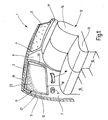
- Figure 1 illustrates the broken cut off rear area a car.
- the figure illustrates a look at the right inside, the one not illustrated left inside is mirror image.
- the illustration is simplified, insofar as, for example, interior structures of the body such as stiffeners, fasteners not shown are, as their representation for the understanding of the invention is not required.
- the terms "right”, “left”, “front”, “rear” used in the way as is customary in the automotive industry.
- the illustrated body section 1 includes Roof 2, from the side of a B-pillar 3 to a not illustrated floor group leads. A corresponding B-pillar would be on the left-hand side of the vehicle to think.
- the roof 2 goes to its trailing edge a tailgate 4 over, in the usual way at the Lower edge of the roof 2 is hinged.
- a rear window 5 is housed in the tailgate 4, in the tailgate 4, in the tailgate 4, a rear window 5 is housed.
- a moving window 12 which in the usual way, for example. Electric is to move up and down to open the window 11.
- foot areas 15 and 16 of the floor group are located between the two rear side doors 7 .
- the gap between the upper edge of the rear seat back 14th and the inner contour of the tailgate 4 is replaced by a hat rack 17 closed when opening the tailgate 4 in known manner is pivoted upward.
- a Trunk available Below the parcel shelf 17 and behind the rear seat back 14 is a Trunk available.
- the located in the side door 7 window 11 is of a lower straight edge 18 and a substantially straight upper edge 19 and two side edges 20 and 21 limited.
- the upper edge 19 extends below, as shown an acute angle to the lower edge 18, i. the distance between the upper edge and the lower edge 18 is greater in the area of the front side edge 21 than in Area of the rear side edge 20.
- Between these edges 18, 19, 20, 21 of the window 11 may be a roller blind 22, as shown to be stretched.
- the roller blind 22 runs through a slot in the lower window reveal.
- the roller blind 22 belongs to a side window roller blind 23, whose for the Understanding the invention essential parts shown in Figure 2 are.
- the side window roller 23 is a manually operated window blind.
- the roller blind 22 is tailored trapezoidal. She is from a first side edge 23, one parallel to it Side edge 24, a top or end edge 25 and a Base edge 26 limited.
- the top or end edge 25 is with a pull-out profile 27 stiffening this edge, which has approximately in the middle of a hook 28, either with the upper edge of the window 12 of the window 11 to is hooked, or in a special eyelet on the inside the side door 7 is to hang.
- the pull-out profile 27 is straight and thus approximates in its course the upper edge 19 of the side window 11 when the shade 22 is pulled out.
- the roller blind 22 thus represents the trapezoidal approximation of the surface of the rear side window 11 dar.
- the pull-out profile 27 is at its ends 29 a Piece far over the side edges 23 and 24 over, in order to retracted state at the edges of the slot hang up through which the roller blind 22 from the interior of the door. 7 is to be pulled out.
- the winding shaft 31 illustrates where the roller blind 22 along its base edge 26, for example by gluing, is attached.
- the winding shaft 31 includes a spring motor 32, which is located in the tubular winding shaft 31, and fixed there at one end.
- the other end of the spring engine 32 which consists for example of a coil spring, is rotatably anchored in a pin 33 in the mounted state rotationally fixed within the door i. between the door inner lining and the door outer skin rotatably held is.
- the winding shaft 31 is rotatable stored.
- the winding shaft 31 Coaxially with the pin 33, the winding shaft 31 has a cylindrical pin 34, with the help of the other End of the winding shaft 31 is rotatably mounted.
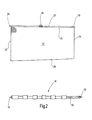
- the structure of the winding shaft 31 is increased in Fig. 3 and shown very schematically.
- To the winding shaft 31 includes a cylindrical tube 35, in which the spring motor 32 is housed.
- the axis of the straight winding shaft 31 immediately below and parallel to the substantially straight lower edge 18 run. So that the top edge 25 of the roller blind 22 runs parallel to the window top edge 19, is the already explained trapezoidal blank required. To wind up this trapezoidal blank that at the end of the winding process the pull-out profile 27 also parallel to the window edge 18th runs, the winding shaft 31 has an at least approximated have frustoconical shape.
- the design regulation states that with the same number of revolutions both the shorter edge 24 and the longer side edge 23 wound have to be. The relationship is linear and leads inevitably to a frustoconical shape. Around are approximately on the tubular core 35th side by side several reels 36a ... 36g attached. everyone this wrap 36a ...
- Each coil 36 has an axial length, accordingly the width of the tape used 37.
- the tape For example, 37 is one on a page self-adhesive textile tape, as well as Handlebar tape is known. There are so many turns applied until the desired diameter at the corresponding Job is reached.
- the band consists of a textile or foil-shaped Carrier 38 and an adhesive layer 39.
- FIGS. 2 and 3 The illustration in FIGS. 2 and 3 is exaggerated, to reveal the essentials. Actually varies the diameter in a practical embodiment of the end with the larger diameter to the end with the smaller diameter, by a maximum of 6 mm to a length of about 50 cm. As it turns out, is the required Cone extremely flat.
- roller blind 22 is only mounted on the coils 36, but not in the spaces.
- the rolls are made of a self-adhesive tape, they are also on the outer peripheral surface of the cylindrical attached to tubular core 35 and can in this way the torque of the spring motor 32 on the blind sheet 22nd transfer.
- the Wickelsinn the individual winding 36 is the same and chosen so that a train on the blind 22nd endeavors to draw the respective winding 36. With In other words, the winding sense of the reel 36 is the same Wickelsinn, as it shows the blind 22, when on the winding shaft 31 is wound up.
- FIG. 3 In the embodiment of Fig. 3 are the individual Winding 36 next to each other in the axial direction. It is but also possible to put the wraps on top of each other, as shown in FIG. 4 reveals.
- the winding shaft 31 in turn belongs to a cylindrical tubular core 35 on which a first coil 41a is applied.
- the winding 41a is in turn made a band 37 together that now, unlike the spiral one Winding in the embodiment of FIG. 3, helically is applied.
- the winding 41a extends from the the pin 34 adjacent end of the core 35 into the Near the core 35, the non-rotatable pin 33 adjacent is.
- the winding 41a covers about 75% of the length of the core 35.
- the individual turns from the band 37 are adjacent to each other at. They do not overlap each other.
- Another, also cylindrical winding 41b is located on the outer peripheral surface of the coil 418a. He begins at the same location at the right end of the core 35, like the winding 41a, but has an axially shorter extent, For example, only 50% of the total length of the Kerns 35. Also it consists of a helically wound up Volume 37. Only for the purpose of better distinction the reel is shown a modified winding sense. In the practical execution, however, it is clear that the The winding sense of the roll 41b is the same as the winding sense of the roll 41a.
- the core 35 carries in the embodiment shown another third roll 41c, also begins at the right end of the core 35 and an axial Length of about 25% of the length of the core 35 has.
- the three wraps 41a ... 41c and the free of diapers Part of the core 35 is in turn a truncated cone in turn approximated.
- the design rule for the frustoconical Approach is the same as already in the Connection with Fig. 3 has been explained.
- FIG. 5 shows an embodiment in which the conical approach using a single roll 42 is produced.
- the winding 42 in turn consists of a band 37, which, as before, on the core 35 side facing self-adhesive is equipped.
- the winding 42 begins, for example at a distance of about 25% of the total length of the core 35 next to the left end.
- the band 37 wound helical. While at the Embodiment of FIG. 4, the slope accordingly the width of the band 37 was chosen so that the individual Windings in the axial direction exactly next to each other lie, a pitch is used in the winding, at the one subsequent turn of the band 37, the preceding one Winding a bit covered.
- the Gradient can produce an increasingly larger winding diameter become.
- the latter embodiment has the essential Advantage that in a machine for winding the tape 37 on the core 35 only one tape needs to be processed and it is sufficient to vary the winding pitch. It is no re-application of the tape 37 is required as this required in the embodiments of FIGS. 3 and 4 is.
- FIG. 5 has been described above with reference to a Example with a sudden change in the gradient, to understand the essentials. It shines, however without further ado, that too is a continuous change
- the pitch of the coil can be generated, which is very fine the cone can be adjusted.
- a window blind for motor vehicles has a roller blind which is trapezoidal tailored to optimally to be adapted to the shape of the window in question.
- the winding shaft for this roller blind is an approximate Truncated cone, with the help of a cylindrical core and Applied to winding is approximated.
Landscapes
- Engineering & Computer Science (AREA)
- Mechanical Engineering (AREA)
- Operating, Guiding And Securing Of Roll- Type Closing Members (AREA)
- Winding Of Webs (AREA)
Abstract
Description
- Fig. 1
- den aufgeschnittenen Fondbereich eines Kraftfahrzeugs mit Blick auf die rechte hintere Seitentür,
- Fig. 2
- die Rollobahn für das Seitenfensterrollo nach Fig. 1, in einer Draufsicht,
- Fig. 3
- ein erstes Ausführungsbeispiel der konischen Wickelwelle des Seitenfensterrollos nach Fig. 1, unter Verwendung nebeneinander angeordneter Wickel,
- Fig. 4
- ein zweites Ausführungsbeispiel der konischen Wickelwelle für das Seitenfensterrollo nach Fig. 1, unter Verwendung von aufeinander liegenden Wickeln, und
- Fig. 5
- ein drittes Ausführungsbeispiel für eine konische Wickelwelle für das Seitenfensterrollo nach Fig. 1, unter Verwendung eines einzigen Wickels mit variabler Steigung.
Claims (14)
- Fensterrollo (11) für Kraftfahrzeuge,
mit einer Wickelwelle (31), die einen Kern (35) mit einer zylindrischen Außenumfangsfläche aufweist,
mit einem ersten auf der Wickelwelle (31) drehfest angeordneten Wickel (36), der von einem Band (37) gebildet ist, das zur Erzeugung des ersten zylindrischen Wickels (37) spiralförmig auf den Kern (38) der Wickelwelle (31) aufgewickelt ist und der sich neben einem Ende des Kerns (35) befindet,
mit wenigstens einem weiteren auf der Wickelwelle (31) angeordneten Wickel (38), der von einem Band (37) gebildet ist, das zur Erzeugung des zylindrischen weiteren Wickels (38) spiralförmig auf den Kern (35) der Wickelwelle (31) aufgewickelt ist, der einen kleineren Außendurchmesser aufweist als der erste Wickel (38) und der sich zwischen dem ersten Wickel (38) und dem anderen Ende des Kern (35) befindet, derart, dass durch die beiden Wickel (38) und den von Wickeln (38) freien Teil des Kerns (35) stufenförmig ein Konus angenähert ist, und
mit einem Rollobahnzuschnitt, der eine von einem Rechteck abweichenden Gestalt aufweist und der mit einer Kante an der Außenumfangsfläche der wenigstens zwei Wickel und dem freien Teil des Kerns befestigt ist. - Fensterrollo (11) für Kraftfahrzeuge,
mit einer Wickelwelle (31), die einen Kern (35) mit einer zylindrischen Außenumfangsfläche aufweist,
mit einem ersten auf der Wickelwelle (31) drehfest angeordneten Wickel (41), der von einem Band (37) gebildet ist, das zur Erzeugung des ersten zylindrischen Wickels (41) schraubenförmig auf den Kern (35) der Wickelwelle (31) aufgewickelt ist und der neben einem Ende des Kerns (35) beginnt und sich ein Stück weit in Richtung auf das andere Ende erstreckt,
mit wenigstens einem weiteren Wickel (41), der von einem Band (37) gebildet ist, das zur Erzeugung des zylindrischen weiteren Wickels (41) schraubenförmig auf den ersten Wickel (41) aufgewickelt ist, und dessen Länge gemessen in Längsrichtung der Wickelwelle (31) kleiner ist als die Länge des ersten Wickels (41), derart, dass durch die beiden Wickel (41) und den von Wickeln (41) freien Teil des Kerns (35) stufenförmig ein Konus angenähert ist, und
mit einem Rollobahnzuschnitt, der eine von einem Rechteck abweichenden Gestalt aufweist und der mit einer Kante an der Außenumfangsfläche der wenigstens zwei Wickel und dem freien Teil des Kerns befestigt ist. - Fensterrollo (11) für Kraftfahrzeuge,
mit einer Wickelwelle (31), die einen Kern (42) mit einer zylindrischen Außenumfangsfläche aufweist,
mit einem auf der Wickelwelle (31) drehfest angeordneten Wickel (42), der von einem Band (37) gebildet ist, das zur Erzeugung des Wickels (42) schraubenförmig auf den Kern (35) der Wickelwelle (31) aufgewickelt ist, wobei sich die Steigung des Wickels (42) in Richtung auf das eine Ende des Kerns (35) kontinuierlich oder sprunghaft verringert, derart, dass durch den Wickel (42) ein Konus angenähert ist, und
mit einem Rollobahnzuschnitt, der eine von einem Rechteck abweichenden Gestalt aufweist und der mit einer Kante an der Außenumfangsfläche der wenigstens zwei Wickel und dem freien Teil des Kerns befestigt ist. - Fensterrollo nach einem der Ansprüche 1, 2 oder 3, dadurch gekennzeichnet, dass eine Endkante (25) mit einem Auszugsprofil (27) versehen ist.
- Fensterrollo nach einem der Ansprüche 1, 2 oder 3, dadurch gekennzeichnet, dass wenigstens eine Seitenkante (23,24) eine gerade Kante ist.
- Fensterrollo nach Anspruch 4, dadurch gekennzeichnet, dass die Endkante (25) gerade ist oder sich aus geraden Abschnitten zusammensetzt.
- Fensterrollo nach Anspruch 1, dadurch gekennzeichnet, dass der Rollobahnzuschnitt (22) aus einem in Wesentlichen undehnbaren Gewirk besteht.
- Fensterrollo nach einem der Ansprüche 1, 2 oder 3, dadurch gekennzeichnet, dass der Wickelwelle (31) einer Antriebseinrichtung (32) zugeordnet ist.
- Fensterrollo nach einem der Ansprüche 1 oder 2, dadurch gekennzeichnet, dass die Wickel (38) zylindrisch sind.
- Fensterrollo nach Anspruch 3, dadurch gekennzeichnet, dass die Wickel (42) konisch sind.
- Fensterrollo nach Anspruch 1, dadurch gekennzeichnet, dass die Wickel (36) in axialer Richtung voneinander beabstandet sind.
- Fensterrollo nach einem der Ansprüche 1, 2 oder 3, dadurch gekennzeichnet, dass die Breite des verwendeten Bandes (37) zwischen 5 mm und 50 mm liegt, wobei jeder Zwischenwert als Grenze eines neuen Bereiches gilt.
- Fensterrollo nach Anspruch 12, dadurch gekennzeichnet, dass das Band (37) ein selbstklebendes Band ist, das auf einer Flachseite mit einer klebfähigen Beschichtung ausgerüstet ist.
- Fensterrollo nach Anspruch 12, dadurch gekennzeichnet, dass das Band (37) aus einem Träger, bestehend aus einem Textil oder einer Folie gebildet ist, das zueinander parallele Kanten aufweist.
Applications Claiming Priority (2)
| Application Number | Priority Date | Filing Date | Title |
|---|---|---|---|
| DE102004030262A DE102004030262B3 (de) | 2004-06-23 | 2004-06-23 | Rollo mit konischer Wickelwelle |
| DE102004030262 | 2004-06-23 |
Publications (2)
| Publication Number | Publication Date |
|---|---|
| EP1609646A2 true EP1609646A2 (de) | 2005-12-28 |
| EP1609646A3 EP1609646A3 (de) | 2007-07-25 |
Family
ID=34981813
Family Applications (1)
| Application Number | Title | Priority Date | Filing Date |
|---|---|---|---|
| EP05012704A Withdrawn EP1609646A3 (de) | 2004-06-23 | 2005-06-14 | Rollo mit konischer Wickelwelle |
Country Status (6)
| Country | Link |
|---|---|
| US (1) | US7243699B2 (de) |
| EP (1) | EP1609646A3 (de) |
| JP (1) | JP2006008122A (de) |
| KR (1) | KR20060049651A (de) |
| CN (1) | CN1712665A (de) |
| DE (1) | DE102004030262B3 (de) |
Cited By (1)
| Publication number | Priority date | Publication date | Assignee | Title |
|---|---|---|---|---|
| CN101688424B (zh) * | 2007-07-06 | 2013-04-24 | 瑞泰控股公司 | 可收回的安全屏障及其操作方法 |
Families Citing this family (10)
| Publication number | Priority date | Publication date | Assignee | Title |
|---|---|---|---|---|
| DE102006023370A1 (de) * | 2006-05-16 | 2007-11-22 | Brose Fahrzeugteile Gmbh & Co. Kommanditgesellschaft, Coburg | Rollo für Fensterscheiben von Kraftfahrzeugen |
| DE102007016154A1 (de) * | 2007-03-21 | 2008-09-25 | Bos Gmbh & Co. Kg | Seitenfensterrollo mit anscharniertem Zugstab und rechteckigem Tragstab |
| TW201036841A (en) * | 2009-04-13 | 2010-10-16 | Macauto Ind Co Ltd | Sunshade for side windows |
| DE102010008766C5 (de) | 2010-02-22 | 2014-04-17 | Webasto SE | Rolloanordnung für ein Kraftfahrzeug |
| US20120018105A1 (en) * | 2010-07-23 | 2012-01-26 | Macauto Industrial Co., Ltd. | Sunshade |
| DE202011052505U1 (de) | 2011-12-28 | 2013-04-09 | Inalfa Roof Systems Group B.V. | Wickelmechanismus einer Sonnenblende, Sonnenblendenanordnung und Dachanordnung |
| FR3001414A1 (fr) * | 2013-01-30 | 2014-08-01 | Renault Sa | Dispositif d'enroulement d'un volet occultant sur un vehicule |
| EP3332998B1 (de) | 2016-12-08 | 2020-04-29 | Inalfa Roof Systems Group B.V. | Wicklungsmechanismus für einen sonnenschutz |
| DE102019106826B4 (de) * | 2019-03-18 | 2022-04-28 | Hbpo Gmbh | Vorrichtung zum Steuern und Führen eines Verschlusselementes |
| WO2021079490A1 (ja) * | 2019-10-25 | 2021-04-29 | 河西工業株式会社 | 車両用サンシェード装置 |
Citations (1)
| Publication number | Priority date | Publication date | Assignee | Title |
|---|---|---|---|---|
| EP0111270A1 (de) | 1982-12-03 | 1984-06-20 | Hüppe GmbH | Rollovorhang |
Family Cites Families (18)
| Publication number | Priority date | Publication date | Assignee | Title |
|---|---|---|---|---|
| US460208A (en) * | 1891-09-29 | lugein | ||
| US1385131A (en) * | 1920-09-15 | 1921-07-19 | Albert R Gwynn | Glare-shade for automobiles |
| US2322934A (en) * | 1941-06-20 | 1943-06-29 | Hicks William Morse | Tackless roller shade assembly |
| US4114756A (en) * | 1976-12-13 | 1978-09-19 | W. R. Grace & Co. | Winding core for heat shrinkable film material |
| DE2841218C3 (de) * | 1978-09-22 | 1982-02-04 | Justin Hüppe GmbH, 2900 Oldenburg | Rollvorhang |
| US5462105A (en) * | 1992-08-07 | 1995-10-31 | Supernak; Janusz | Adjustments for window shades |
| US5551744A (en) * | 1995-01-12 | 1996-09-03 | Energy Conservation Partnership, Ltd. | Motor vehicle windshield curtain structure |
| FR2750158B1 (fr) * | 1996-06-20 | 1998-11-27 | Farnier Et Penin Snc | Store a enrouleur a rattrapage conique |
| US6047762A (en) * | 1998-03-20 | 2000-04-11 | Prince Corporation | Shade control for a vehicle window |
| DE19925226C2 (de) * | 1999-06-01 | 2002-10-10 | Eva Fahrzeugtechnik Gmbh | Verdunklungsvorrichtung |
| DE10020212B4 (de) * | 2000-04-25 | 2004-02-19 | Bos Gmbh & Co. Kg | Seitenfensterrollo mit Schlitzabdeckung |
| US6488069B1 (en) * | 2000-07-20 | 2002-12-03 | Dometic Corporation | Rain dump structure for awning |
| FR2816983B1 (fr) * | 2000-11-22 | 2003-01-10 | Wagon Automotive Snc | Store a enrouleur a support d'enroulement tronconique a degres |
| DE10151872B4 (de) * | 2001-10-24 | 2007-10-04 | Bos Gmbh & Co. Kg | Geteiltes Fensterrollo für Kraftfahrzeuge |
| DE10204331B4 (de) * | 2002-02-01 | 2005-10-27 | Bos Gmbh & Co. Kg | Rolloartige Anordnung mit längsgeteilter Wickelwelle |
| US6681832B1 (en) * | 2002-07-01 | 2004-01-27 | Carla Procida | Window screen assembly for vehicle |
| DE10354233A1 (de) * | 2003-11-19 | 2005-06-30 | Bos Gmbh & Co. Kg | Seitenfensterrollo mit Konturteil |
| US7013946B2 (en) * | 2004-01-08 | 2006-03-21 | Reum Protec Gmbh | Roller blind, particularly window roller blind, for motor vehicles |
-
2004
- 2004-06-23 DE DE102004030262A patent/DE102004030262B3/de not_active Expired - Fee Related
-
2005
- 2005-06-14 EP EP05012704A patent/EP1609646A3/de not_active Withdrawn
- 2005-06-21 JP JP2005180130A patent/JP2006008122A/ja not_active Withdrawn
- 2005-06-22 KR KR1020050053831A patent/KR20060049651A/ko not_active Application Discontinuation
- 2005-06-22 CN CNA2005100790788A patent/CN1712665A/zh active Pending
- 2005-06-23 US US11/159,699 patent/US7243699B2/en not_active Expired - Fee Related
Patent Citations (1)
| Publication number | Priority date | Publication date | Assignee | Title |
|---|---|---|---|---|
| EP0111270A1 (de) | 1982-12-03 | 1984-06-20 | Hüppe GmbH | Rollovorhang |
Cited By (1)
| Publication number | Priority date | Publication date | Assignee | Title |
|---|---|---|---|---|
| CN101688424B (zh) * | 2007-07-06 | 2013-04-24 | 瑞泰控股公司 | 可收回的安全屏障及其操作方法 |
Also Published As
| Publication number | Publication date |
|---|---|
| DE102004030262B3 (de) | 2006-04-27 |
| CN1712665A (zh) | 2005-12-28 |
| US7243699B2 (en) | 2007-07-17 |
| JP2006008122A (ja) | 2006-01-12 |
| KR20060049651A (ko) | 2006-05-19 |
| EP1609646A3 (de) | 2007-07-25 |
| US20060000566A1 (en) | 2006-01-05 |
Similar Documents
| Publication | Publication Date | Title |
|---|---|---|
| EP1609646A2 (de) | Rollo mit konischer Wickelwelle | |
| EP1970235B1 (de) | Seitenfensterrollo mit Seilantrieb | |
| EP1612070B1 (de) | Fensterrollo für gekrümmte oder nicht rechteckige Fahrzeugfenster | |
| DE102007011465B4 (de) | Rollo mit Lochbandantrieb | |
| DE60215941T2 (de) | Bremsvorrichtung für rollos und dergleichen | |
| DE3631488A1 (de) | Abdeckplatte fuer einen fahrzeug-innenraum | |
| DE3145277A1 (de) | Drahtantriebsvorrichtung fuer einen fensterregler | |
| WO2006034690A1 (de) | Rolloanordnung für ein kraftfahrzeug | |
| DE10331514A1 (de) | Sonnenschutzbaugruppe für ein Fahrzeugdach | |
| DE19640846B4 (de) | Rollowelle zum Auf- und Abrollen eines flexiblen Flächengebildes | |
| DE102006046069A1 (de) | Fensterrollo mit reibungsmindertem Antrieb | |
| EP1621382A1 (de) | Fensterrollo mit unterschiedlicher Lichtdurchlässigkeit | |
| EP1652705B1 (de) | Stufenfreie Rolloanordnung | |
| EP1986876B1 (de) | Verdunkelungsvorrichtung für eine lichtdurchlässige scheibe, insbesondere für kraftfahrzeuge | |
| EP3676117B1 (de) | Rolloanordnung mit wickelwellenhüllrohr | |
| DE19538551C1 (de) | Sonnenschutz für ein Fahrzeugdach | |
| DE10215678B4 (de) | Beschattungseinrichtung für eine Scheibe | |
| DE3835891C2 (de) | ||
| DE60213903T2 (de) | Vorhang mit Spiralfeder | |
| EP0529591B1 (de) | Rolloanordnung, vorzugsweise für Kraftfahrzeugheckscheiben | |
| DE3536189A1 (de) | Rollo-vorrichtung fuer fenster | |
| EP1972477B1 (de) | Seitenfensterrollo mit anscharniertem Zugstab und rechteckigem Tragstab | |
| DE102008061215A1 (de) | Kraftfahrzeug mit Rollo an Fahrzeugtürenfenster | |
| DE202006017838U1 (de) | Fensterrollo mit reibungsgemindertem Antrieb | |
| DE102004015396B4 (de) | Fensterrollo mit integriertem Wickelausgleich |
Legal Events
| Date | Code | Title | Description |
|---|---|---|---|
| PUAI | Public reference made under article 153(3) epc to a published international application that has entered the european phase |
Free format text: ORIGINAL CODE: 0009012 |
|
| AK | Designated contracting states |
Kind code of ref document: A2 Designated state(s): AT BE BG CH CY CZ DE DK EE ES FI FR GB GR HU IE IS IT LI LT LU MC NL PL PT RO SE SI SK TR |
|
| AX | Request for extension of the european patent |
Extension state: AL BA HR LV MK YU |
|
| PUAL | Search report despatched |
Free format text: ORIGINAL CODE: 0009013 |
|
| AK | Designated contracting states |
Kind code of ref document: A3 Designated state(s): AT BE BG CH CY CZ DE DK EE ES FI FR GB GR HU IE IS IT LI LT LU MC NL PL PT RO SE SI SK TR |
|
| AX | Request for extension of the european patent |
Extension state: AL BA HR LV MK YU |
|
| 17P | Request for examination filed |
Effective date: 20070810 |
|
| 17Q | First examination report despatched |
Effective date: 20070925 |
|
| AKX | Designation fees paid |
Designated state(s): AT BE BG CH CY CZ DE DK EE ES FI FR GB GR HU IE IS IT LI LT LU MC NL PL PT RO SE SI SK TR |
|
| GRAP | Despatch of communication of intention to grant a patent |
Free format text: ORIGINAL CODE: EPIDOSNIGR1 |
|
| STAA | Information on the status of an ep patent application or granted ep patent |
Free format text: STATUS: THE APPLICATION IS DEEMED TO BE WITHDRAWN |
|
| 18D | Application deemed to be withdrawn |
Effective date: 20090409 |