EP1602786A2 - Seilwindenanordnung - Google Patents
Seilwindenanordnung Download PDFInfo
- Publication number
- EP1602786A2 EP1602786A2 EP05011317A EP05011317A EP1602786A2 EP 1602786 A2 EP1602786 A2 EP 1602786A2 EP 05011317 A EP05011317 A EP 05011317A EP 05011317 A EP05011317 A EP 05011317A EP 1602786 A2 EP1602786 A2 EP 1602786A2
- Authority
- EP
- European Patent Office
- Prior art keywords
- cable winch
- assembly according
- anchoring point
- coupling
- uncoupling
- Prior art date
- Legal status (The legal status is an assumption and is not a legal conclusion. Google has not performed a legal analysis and makes no representation as to the accuracy of the status listed.)
- Granted
Links
Images


Classifications
-
- B—PERFORMING OPERATIONS; TRANSPORTING
- B66—HOISTING; LIFTING; HAULING
- B66C—CRANES; LOAD-ENGAGING ELEMENTS OR DEVICES FOR CRANES, CAPSTANS, WINCHES, OR TACKLES
- B66C1/00—Load-engaging elements or devices attached to lifting or lowering gear of cranes or adapted for connection therewith for transmitting lifting forces to articles or groups of articles
- B66C1/10—Load-engaging elements or devices attached to lifting or lowering gear of cranes or adapted for connection therewith for transmitting lifting forces to articles or groups of articles by mechanical means
-
- B—PERFORMING OPERATIONS; TRANSPORTING
- B66—HOISTING; LIFTING; HAULING
- B66D—CAPSTANS; WINCHES; TACKLES, e.g. PULLEY BLOCKS; HOISTS
- B66D1/00—Rope, cable, or chain winding mechanisms; Capstans
- B66D1/60—Rope, cable, or chain winding mechanisms; Capstans adapted for special purposes
-
- E—FIXED CONSTRUCTIONS
- E02—HYDRAULIC ENGINEERING; FOUNDATIONS; SOIL SHIFTING
- E02F—DREDGING; SOIL-SHIFTING
- E02F3/00—Dredgers; Soil-shifting machines
- E02F3/04—Dredgers; Soil-shifting machines mechanically-driven
- E02F3/28—Dredgers; Soil-shifting machines mechanically-driven with digging tools mounted on a dipper- or bucket-arm, i.e. there is either one arm or a pair of arms, e.g. dippers, buckets
- E02F3/36—Component parts
- E02F3/3604—Devices to connect tools to arms, booms or the like
- E02F3/3609—Devices to connect tools to arms, booms or the like of the quick acting type, e.g. controlled from the operator seat
-
- E—FIXED CONSTRUCTIONS
- E02—HYDRAULIC ENGINEERING; FOUNDATIONS; SOIL SHIFTING
- E02F—DREDGING; SOIL-SHIFTING
- E02F3/00—Dredgers; Soil-shifting machines
- E02F3/04—Dredgers; Soil-shifting machines mechanically-driven
- E02F3/96—Dredgers; Soil-shifting machines mechanically-driven with arrangements for alternate or simultaneous use of different digging elements
- E02F3/961—Dredgers; Soil-shifting machines mechanically-driven with arrangements for alternate or simultaneous use of different digging elements with several digging elements or tools mounted on one machine
-
- E—FIXED CONSTRUCTIONS
- E02—HYDRAULIC ENGINEERING; FOUNDATIONS; SOIL SHIFTING
- E02F—DREDGING; SOIL-SHIFTING
- E02F9/00—Component parts of dredgers or soil-shifting machines, not restricted to one of the kinds covered by groups E02F3/00 - E02F7/00
- E02F9/20—Drives; Control devices
- E02F9/2016—Winches
Definitions
- the present invention relates to a winch assembly for a vehicle, in particular for a piste preparation vehicle, with a winch and a rope, as well as with one the cable arranged coupling device for coupling and uncoupling at an external Anchor point. Moreover, the invention relates to a vehicle with such Winch arrangement.
- the driver has to get out of his vehicle and the front end of the rope with the coupling device on the provided Hang in the anchoring point. Since the rope with the coupling element considerable weight the driver is exposed to high physical loads. In addition, the driver When leaving sometimes with dangerous conditions, such as steepness of the Terrain, slope conditions (high amounts of snow or icy surface of the slope) that make manual hanging difficult.
- Object of the present invention is therefore to provide a winch assembly of the above to propose the type mentioned above, the above-mentioned disadvantages of the prior Technology avoids.
- the arrangement is a device for remote-controlled coupling and / or uncoupling of the coupling device.
- the coupling device of the rope be automatically connected to the external anchor point without the Driver has to leave his vehicle.
- Manual suspension or coupling with the anchoring point is dispensable. This makes the work of the driver significant makes it easier to connect or disconnect quickly and easily.
- Remote Controlled Coupling and / or decoupling means, in particular, all those measures which or decoupling the coupling device at the anchoring point of the vehicle, preferably from the driver's cab, without the need for the rope manually insert and remove.
- a preferred embodiment of the invention provides that the cable winch assembly a winch arm through which or on which the rope is feasible, wherein preferably the Windenarm by the device for remote controlled andloder uncoupling movable is.
- the winch arm operated remotely and without Movement restriction can be controlled. This has besides the advantage of an improved Mobility also saves time.
- the winch arm itself can be hydraulic In addition, the turning and pivoting by 360 ° and a lateral Tilting allowed.
- the winch arm at least one opposite him movable arm, preferably at least one telescopically movable arm, through which the coupling device to the external anchor point at least approachable.
- the movable arm or the telescopically movable Boom also be pivotally mounted on the winch arm.
- the vehicle can with it Distance to the anchoring point to be positioned, as it is due to the terrain shape and the terrain is not always possible to approach very close to this.
- the Coupling device has at least one magnet through which the Coupling device can be coupled to the external anchor point.
- the at least one magnet is an electromagnet, by the device for remote on and / or Uncoupling is activated.
- the Coupling device a sensor device, preferably a touch sensor, comprises, via which the electromagnet is activated.
- the electromagnet on the Power supplied to the device according to the invention and thereby causes adhesion of the Magnets at a designated location at the anchor point.
- the coupling device a Fastening element, preferably a hook-shaped device, which, to the external anchoring point can be coupled.
- the coupling device one, preferably hydraulic, blocking device includes, via which it connects to the external Anchoring point is fixable. It is advantageously provided that the blocking device can be activated via the device for remote control and / or uncoupling.
- the Blocking device can with a hydraulically operated locking bolt be realized with a corresponding device on the external Anchoring point cooperates.
- the blocking device also be electrically operated.
- the coupling element is a preferably substantially spherical body which is arranged for receiving in a at the external anchoring point or trained holding device is provided.
- the external anchoring point has a pocket-shaped holding device, in which the in Essentially spherical body is insertable.
- the bag-shaped holding device is a metallic plate includes, which is bent up at two corners. The spherical body can in the process Resulting cavity recording.
- a further embodiment of the invention provides that the device for remote controlled arrival and / or uncoupling from the interior of the vehicle is activated.
- the driver of the vehicle can remain in the cab and the coupling process in control clear way.
- the device for remote arrival and / or uncoupling a wireless Transmission device comprises.
- a radio or Infrared remote control find use. This makes it possible for the driver to also can refer to a favorable location position, where he targeted the coupling process can control.
- a reversal solution may also be provided be.
- the external anchor point is a remote-controlled can have releasable holding device. This can be done, for example, with a magnet, preferably carried out an electromagnet, which for coupling and / or uncoupling with the Coupling device is provided.
- the external Anchoring point a sensor device, preferably a touch sensor, has, by which the electromagnet is activated.
- the external Anchoring point have an electrical locking device over which the Coupling device on and / or can be decoupled, the power supply via the Anchoring point takes place.
- the Power supply for example, from the junction boxes of snowmaking systems can be removed.
- the electrical blocking device by the device for remote on and / or Uncoupling is activated.
- the external anchoring point can be wireless Have transmission means by which the electromagnet and / or the electrical Blocking device is activated.
- This wireless transmission device can for example, via a conventional radio link or an infrared transmitting / receiving unit will be realized.
- the vehicle according to the invention is characterized by an above-described Cable winch assembly according to the accompanying claims.
- Fig. 1 shows a first schematically illustrated embodiment of the present invention Invention, a piste preparation vehicle 1 with a cable drum 2 mounted thereon represents.
- This cable drum 2 serves for receiving and winding or unwinding of a rope 3, at the end of a coupling device 4 is arranged.
- this rope 3 by means of its coupling device: 4 on a fixed to the external anchoring point 5, so that the runway preparation vehicle 1 at Ab- or ascending the runway in terms of accidental slipping is secured.
- the rope 3 is guided in or on a winch arm 6, the pivoting, tilt and is height-adjustable mounted on slope preparation vehicle 1.
- Coupling device 4 are moved so as shown in detail 7.
- the winch arm 6 has a relative to him movable arm 8, which in Shape of a telescopic boom can be realized.
- This arm 8 can from the Device for remote connection and / or uncoupling be moved so that the Coupling device 4 to the example shown holding device 9 in the form of a Ringes the external anchor point 5 can be performed.
- the coupling device 4 and the holding device 9 for reasons of clarity shown in simplified form.
- the coupling device 4 can also be an electromagnet have, by the means for remote arrival and / or decoupling is activatable.
- the activation can take place with a touch sensor, wherein upon contact of coupling device 4 and holding device 9 of the external Anchoring point 5 of the solenoid is attached to its adhesion with electricity.
- the Touch sensor may also cooperate with a blocking device that the Coupling device 4 on the holding device 9, for example, with a hydraulic fixed sliding bolt fixed.
- the device for remote controlled and / or Uncoupling may conveniently from inside the PistenprpparationsInstitutes. 1 be activated or actuated, wherein the driver can remain in the cab 10.
- the inventive Device also a wireless transmission device, for example in the form of a Radio or infrared transmitting / receiving unit is realized. The driver can then For example, by means of a remote control the coupling process at a favorable Control the place.
- Fig. 2 shows a variant of the invention, wherein the winch arm 6 at least one telescopic movable boom 11 is arranged on the winch arm 6.
- This boom 11 can so be constructed so that it is adjustable in height, length and tilt angle. This allows a structurally simple solution for automated coupling the coupling device 4 with the holding element 9 of the external anchoring element. 5 be proposed.
- the telescopically movable boom 11 can from the device be guided to the holding element 9 for remote arrival and / or decoupling, that a coupling without manual intervention is possible.
- Fig. 3 shows a further schematically illustrated embodiment of the present invention Invention.
- the coupling device 4 by means of a Additional arm 12 brought to the holding device 9 of the external anchoring point 5 become.
- the additional arm 12 can be designed so that this also in height, Length and at an angle relative to the shield frame 13 is adjustably mounted.
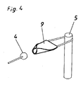
- Fig. 4 shows a schematically illustrated embodiment for the realization of a detachable connection between coupling device 4 and holding device 9 of the external Anchoring point 5.
- the coupling device 4 has in the figure shown a spherical body, which is provided for receiving in the holding device 9.
- the Holding device 9 comprises in the figure shown a metallic plate whose corners on the bent to the coupling device end are bent up. As a result, a fancy Cavity, which tapers to the coupling device 9 out.
- the spherical body is in the holding device 9 hung, so that the slope preparation vehicle 1 coupled to this connection can drive on the steep slope.
Landscapes
- Engineering & Computer Science (AREA)
- Mechanical Engineering (AREA)
- Mining & Mineral Resources (AREA)
- Civil Engineering (AREA)
- General Engineering & Computer Science (AREA)
- Structural Engineering (AREA)
- Refuge Islands, Traffic Blockers, Or Guard Fence (AREA)
- Flexible Shafts (AREA)
- Details Of Connecting Devices For Male And Female Coupling (AREA)
- Vehicle Cleaning, Maintenance, Repair, Refitting, And Outriggers (AREA)
- Selective Calling Equipment (AREA)
- Jib Cranes (AREA)
Abstract
Description
- Fig. 1
- ein schematisch dargestelltes Pistenpräparationsfahrzeug mit einer Seilwindenanordnung gemäß der vorliegenden Erfindung,
- Fig. 2
- ein weiteres Ausführungsbeispiel der Erfindung.
- Fig. 3
- ein Pistenpräparationsfahrzeug mit einer Seilwindenanordnung in einer weiteren Ausführungsform, und
- Fig.4
- ein schematisch dargestelltes Detail einer Kupplungsvorrichtung mit einem Halteelement eines Verankerungspunktes.
Claims (22)
- Seilwindenanordnung für ein Fahrzeug, insbesondere für ein Pistenpräparationsfahrzeug, mit einer Seilwinde und einem Seil, sowie mit einer an dem Seil angeordneten Kupplungsvorrichtung zum An- und Abkoppeln an einem externen Verankerungspunkt, dadurch gekennzeichnet, dass die Anordnung eine Einrichtung zum ferngesteuerten An- und/oder Abkoppeln der Kupplungsvorrichtung (4) aufweist.
- Seilwindenanordnung nach Anspruch 1, dadurch gekennzeichnet, dass sie einen Windenarm (6) aufweist, durch den bzw. an dem das Seil (3) führbar ist.
- Seilwindenanordnung nach Anspruch 2, dadurch gekennzeichnet, dass der Windenarm (6) durch die Einrichtung zum ferngesteuerten An- und/oder Abkoppeln bewegbar ist.
- Seilwindenanordnung nach Anspruch 2 oder 3, dadurch gekennzeichnet, dass der Windenarm (6) mindestens einen gegenüber ihm bewegbaren Arm (8), vorzugsweise mindestens einen teleskopisch verfahrbaren Ausleger, aufweist, durch den die Kupplungsvorrichtung (4) an den externen Verankerungspunkt (5) zumindest annäherbar ist.
- Seilwindenanordnung nach einem der Ansprüche 1 bis 4, dadurch gekennzeichnet, dass die Kupplungsvorrichtung (4) zumindest einen Magneten aufweist, durch den die Kupplungsvorrichtung (4) an den externen Verankerungspunkt (5) koppelbar ist.
- Seilwindenanordnung nach Anspruch 5, dadurch gekennzeichnet, dass der zumindest eine Magnet ein Elektromagnet ist, der durch die Einrichtung zum ferngesteuerten An- und/oder Abkuppeln aktivierbar ist.
- Seilwindenanordnung nach Anspruch 6, dadurch gekennzeichnet, dass die Kupplungsvorrichtung (4) eine Sensorvorrichtung, vorzugsweise einen Berührungssensor, umfasst, über die der Elektromagnet aktivierbar ist.
- Seilwindenanordnung nach einem der Ansprüche 1 bis 7, dadurch gekennzeichnet, dass die Kupplungsvorrichtung (4) ein Befestigungselement, vorzugsweise eine hakenförmige Vorrichtung, aufweist, welches an den externen Verankerungspunkt (5) koppelbar ist.
- Seilwindenanordnung nach einem der Ansprüche 1 bis 8, dadurch gekennzeichnet, dass die Kupplungsvorrichtung (4) eine, vorzugsweise hydraulische, Blockierungseinrichtung umfasst, über die sie an den externen Verankerungspunkt (5) fixierbar ist.
- Seilwindenanordnung nach Anspruch 9, dadurch gekennzeichnet, dass die Blockierungseinrichtung über die Einrichtung zum ferngesteuerten An- und/oder Abkuppeln aktivierbar ist.
- Seilwindenanordnung nach einem der Ansprüche 1 bis 10, dadurch gekennzeichnet, dass das Kupplungselement (4) einen vorzugsweise im Wesentlichen kugelförmigen Körper umfasst, der zur Aufnahme in einer an dem externen Verankerungspunkt (5) angeordneten oder ausgebildeten Haltevorrichtung (9) vorgesehen ist.
- Seilwindenanordnung nach Anspruch 11, dadurch gekennzeichnet, dass der externe Verankerungspunkt (5) eine taschenförmige Haltevorrichtung aufweist, in die der im Wesentlichen kugelförmige Körper einlegbar ist.
- Seilwindenanordnung nach Anspruch 12, dadurch gekennzeichnet, dass die taschenförmige Haltevorrichtung (9) eine metallische Platte umfasst, die an zwei Ecken hochgebogen ist.
- Seilwindenanordnung nach einem der Ansprüche 1 bis 13, dadurch gekennzeichnet, dass die Einrichtung zum ferngesteuerten An- und/oder Abkuppeln aus dem Inneren des Fahrzeuges (1) aktivierbar ist.
- Seilwindenanordnung nach einem der Ansprüche 1 bis 14, dadurch gekennzeichnet, dass die Einrichtung zum ferngesteuerten An- und/oder Abkoppeln eine drahtlose Übertragungseinrichtung umfasst.
- Seilwindenanordnung nach einem der Ansprüche 1 bis 15, dadurch gekennzeichnet, dass der externe Verankerungspunkt (5) eine ferngesteuerte lösbare Haltevorrichtung (9) aufweist.
- Seilwindenanordnung nach einem der Ansprüche 1 bis 16, dadurch gekennzeichnet, dass der externe Verankerungspunkt (5) einen Magneten, vorzugsweise einen Elektromagneten, aufweist, der zum An- und/oder Abkoppeln mit der Kupplungsvorrichtung (4) vorgesehen ist.
- , Seilwindenanordnung nach Anspruch 17. dadurch gekennzeichnet, dass der externe Verankerungspunkt (5) eine Sensorvorrichtung, vorzugsweise einen Berührungssensor, aufweist, durch die der Elektromagnet aktivierbar ist.
- Seilwindenanordnung nach einem der Ansprüche 1 bis 18, dadurch gekennzeichnet, dass der externe Verankerungspunkt (5) eine elektrische Blockierungseinrichtung aufweist, über die die Kupplungsvorrichtung (4) an- und/oder abkoppelbar ist.
- Seilwindenanordnung nach Anspruch 19, dadurch gekennzeichnet, dass die elektrische Blockierungsvorrichtung durch die Einrichtung zum ferngesteuerten An- und/oder Abkoppeln aktivierbar ist.
- Seilwindenanordnung nach Anspruch 19 oder 20, dadurch gekennzeichnet, dass der externe Verankerungspunkt (5) eine drahtlose Übertragungseinrichtung aufweist, durch die der Elektromagnet und/oder die elektrische Blockierungseinrichtung aktivierbar ist.
- Fahrzeug mit einer Seilwindenanordnung nach einem der Ansprüche 1 bis 21.
Applications Claiming Priority (2)
| Application Number | Priority Date | Filing Date | Title |
|---|---|---|---|
| AT9682004 | 2004-06-04 | ||
| AT0096804A AT502564B1 (de) | 2004-06-04 | 2004-06-04 | Pistenpräparationsfahrzeug mit einer seilwinde |
Publications (3)
| Publication Number | Publication Date |
|---|---|
| EP1602786A2 true EP1602786A2 (de) | 2005-12-07 |
| EP1602786A3 EP1602786A3 (de) | 2011-05-11 |
| EP1602786B1 EP1602786B1 (de) | 2013-07-17 |
Family
ID=34936918
Family Applications (1)
| Application Number | Title | Priority Date | Filing Date |
|---|---|---|---|
| EP05011317.4A Expired - Lifetime EP1602786B1 (de) | 2004-06-04 | 2005-05-25 | Pistenpräparationsfahrzeug mit einer Seilwindenanordnung. |
Country Status (4)
| Country | Link |
|---|---|
| US (1) | US7530547B2 (de) |
| EP (1) | EP1602786B1 (de) |
| AT (1) | AT502564B1 (de) |
| CA (1) | CA2509127C (de) |
Cited By (2)
| Publication number | Priority date | Publication date | Assignee | Title |
|---|---|---|---|---|
| EP2267227A2 (de) | 2009-06-03 | 2010-12-29 | Kässbohrer Geländefahrzeug AG | Kraftfahrzeug mit einer Seilwindenanordnung |
| EP3372733A1 (de) | 2017-03-07 | 2018-09-12 | ELMA-TECH Modern Technologies | Sicherungseinrichtung |
Families Citing this family (15)
| Publication number | Priority date | Publication date | Assignee | Title |
|---|---|---|---|---|
| ATE451290T1 (de) | 2006-10-06 | 2009-12-15 | Rolic Invest Sarl | Raupenfahrzeug |
| ATE463412T1 (de) * | 2006-10-06 | 2010-04-15 | Rolic Invest Sarl | Raupenfahrzeug |
| ITMI20071249A1 (it) * | 2007-06-21 | 2008-12-22 | Rolic Invest Sarl | Rampone per cingoli di veicoli cingolati, in particolare veicoli battipista |
| DE202007009639U1 (de) * | 2007-07-10 | 2008-11-27 | Liebherr-Werk Ehingen Gmbh | Fahrzeugkran |
| ITMI20072096A1 (it) | 2007-10-30 | 2009-04-30 | Rolic Invest Sarl | Dispositivo di collegamento fra un veicolo battipista ed un'attrezzatura per la preparazione del manto nevoso delle piste da sci e metodo di controllo impiegante tale dispositivo di collegamento |
| ITMI20072091A1 (it) * | 2007-10-30 | 2009-04-30 | Rolic Invest Sarl | Fresa rotante da neve e metodo per la preparazione del manto nevoso delle piste da sci |
| ITMI20072105A1 (it) * | 2007-10-31 | 2009-05-01 | Rolic Invest Sarl | Fresa rotante da neve per la preparazione del manto nevoso delle piste da sci |
| ITMI20072102A1 (it) * | 2007-10-31 | 2009-05-01 | Rolic Invest Sarl | Fresa rotante da neve per la preparazione del manto nevoso delle piste da sci |
| ITMI20081001A1 (it) * | 2008-05-29 | 2009-11-30 | Rolic Invest Sarl | Cingolo per veicoli battipista e veicolo battipista provvisto di tale cingolo |
| IT1394923B1 (it) | 2009-02-18 | 2012-07-27 | Rolic Invest Sarl | Veicolo battipista comprendente un gruppo verricello di ausilio alla movimentazione del veicolo battipista lungo pendii ripidi e metodo di azionamento del gruppo verricello |
| US9303386B2 (en) * | 2009-03-29 | 2016-04-05 | Stephen T. Schmidt | Tool attachments on an auto-powered mobile machine |
| USD630551S1 (en) | 2009-10-23 | 2011-01-11 | Rolic Invest S.Ar.L. | Snow groomer |
| FR2981300B1 (fr) * | 2011-10-13 | 2013-12-20 | Aztec | Bati retractable pour vehicule d'entretien de pistes skiables |
| CN114537060A (zh) * | 2020-11-24 | 2022-05-27 | 普瑞诺斯股份公司 | 用于准备滑雪道的履带式车辆和控制履带式车辆的绞盘的方法 |
| IT202100032639A1 (it) * | 2021-12-24 | 2023-06-24 | Prinoth Spa | Gruppo verricello di ausilio alla movimentazione di un veicolo cingolato e relativo metodo di controllo |
Citations (5)
| Publication number | Priority date | Publication date | Assignee | Title |
|---|---|---|---|---|
| US3357510A (en) | 1964-03-05 | 1967-12-12 | Jourdan Daniel | System for enabling motor vehicles to climb obstacles |
| EP0761890A1 (de) | 1995-09-07 | 1997-03-12 | MDP Meccanica del Piave S.p.A. | Sicherheitsvorrichtung für Kraftfahrzeuge mit einer Manövrierwinde auf stark geneigter Ebene |
| DE10045524A1 (de) | 2000-09-13 | 2002-03-21 | Kaessbohrer Gelaendefahrzeug | Pistenpflegevorrichtung, Pistenpflegefahrzeug und Verfahren zum Betreiben einer Pistenpflegevorrichtung |
| EP1331198A1 (de) | 2002-01-25 | 2003-07-30 | Kässbohrer Geländefahrzeug AG | Windeneinheit für ein Pistenfahrzeug |
| EP1418275A2 (de) | 2002-11-08 | 2004-05-12 | Kässbohrer Geländefahrzeug AG | Verfahren zur Steuerung eines Pistenpflegefahrzeugs und Pistenpflegefahrzeug |
Family Cites Families (11)
| Publication number | Priority date | Publication date | Assignee | Title |
|---|---|---|---|---|
| US3104015A (en) * | 1960-06-13 | 1963-09-17 | Adolph E Goldfarb | Toy crane |
| DE1226056B (de) * | 1964-03-23 | 1966-10-06 | Shell Int Research | Einrichtung zum Anschliessen einer Rohrleitung von einer oberhalb der Wasseroberflaeche befindlichen Arbeitsstation aus an eine Unterwasseranlage |
| DE1944944A1 (de) * | 1969-09-04 | 1971-03-18 | Jeffes Robert Henry Francis | Teleskop-Zugstange |
| US3692119A (en) * | 1971-04-23 | 1972-09-19 | Jasper J Tucker | Winch carrying snow grooming vehicle supported by skids and powered by an anchored drawline |
| US3926316A (en) * | 1975-02-14 | 1975-12-16 | Argil W Luttrell | Mobile sit-on toy crane |
| US5035336A (en) * | 1987-04-20 | 1991-07-30 | Schmitz Robert J | Compact collapsible manhole cover lifter |
| US4789072A (en) * | 1987-04-20 | 1988-12-06 | Quam Dean R | Hydraulic manhole cover lifter |
| US5505578A (en) * | 1995-05-15 | 1996-04-09 | Fuller; Keith L. | Transportable hoist for lifting large vehicle wheels |
| US6945742B2 (en) * | 2002-06-20 | 2005-09-20 | Dave Roberts | Portable manhole cover remover |
| US7004456B2 (en) * | 2002-10-03 | 2006-02-28 | Key Energy Services, Inc. | Engine speed limiter for a hoist |
| DE102004025973B4 (de) | 2004-05-18 | 2006-10-26 | Kässbohrer Geländefahrzeug AG | Vorrichtung zum Verankern eines flexiblen Winden-Zugmittels an einem ortsfesten Ankerteil |
-
2004
- 2004-06-04 AT AT0096804A patent/AT502564B1/de not_active IP Right Cessation
-
2005
- 2005-05-25 EP EP05011317.4A patent/EP1602786B1/de not_active Expired - Lifetime
- 2005-06-03 CA CA2509127A patent/CA2509127C/en not_active Expired - Fee Related
- 2005-06-03 US US11/143,497 patent/US7530547B2/en active Active
Patent Citations (5)
| Publication number | Priority date | Publication date | Assignee | Title |
|---|---|---|---|---|
| US3357510A (en) | 1964-03-05 | 1967-12-12 | Jourdan Daniel | System for enabling motor vehicles to climb obstacles |
| EP0761890A1 (de) | 1995-09-07 | 1997-03-12 | MDP Meccanica del Piave S.p.A. | Sicherheitsvorrichtung für Kraftfahrzeuge mit einer Manövrierwinde auf stark geneigter Ebene |
| DE10045524A1 (de) | 2000-09-13 | 2002-03-21 | Kaessbohrer Gelaendefahrzeug | Pistenpflegevorrichtung, Pistenpflegefahrzeug und Verfahren zum Betreiben einer Pistenpflegevorrichtung |
| EP1331198A1 (de) | 2002-01-25 | 2003-07-30 | Kässbohrer Geländefahrzeug AG | Windeneinheit für ein Pistenfahrzeug |
| EP1418275A2 (de) | 2002-11-08 | 2004-05-12 | Kässbohrer Geländefahrzeug AG | Verfahren zur Steuerung eines Pistenpflegefahrzeugs und Pistenpflegefahrzeug |
Cited By (6)
| Publication number | Priority date | Publication date | Assignee | Title |
|---|---|---|---|---|
| EP2267227A2 (de) | 2009-06-03 | 2010-12-29 | Kässbohrer Geländefahrzeug AG | Kraftfahrzeug mit einer Seilwindenanordnung |
| DE102009024644A1 (de) | 2009-06-03 | 2011-01-27 | Kässbohrer Geländefahrzeug AG | Kraftfahrzeug mit einer Seilwindeanordnung |
| DE102009024644B4 (de) * | 2009-06-03 | 2012-11-15 | Kässbohrer Geländefahrzeug AG | Pistenraupe mit einer Seilwindenanordnung |
| EP3372733A1 (de) | 2017-03-07 | 2018-09-12 | ELMA-TECH Modern Technologies | Sicherungseinrichtung |
| AT519704A1 (de) * | 2017-03-07 | 2018-09-15 | Elma Tech Modern Tech | Sicherungseinrichtung |
| AT519704B1 (de) * | 2017-03-07 | 2020-07-15 | Elma Tech Modern Tech Og | Sicherungseinrichtung |
Also Published As
| Publication number | Publication date |
|---|---|
| EP1602786B1 (de) | 2013-07-17 |
| CA2509127C (en) | 2014-05-27 |
| AT502564B1 (de) | 2008-06-15 |
| AT502564A1 (de) | 2007-04-15 |
| US7530547B2 (en) | 2009-05-12 |
| EP1602786A3 (de) | 2011-05-11 |
| CA2509127A1 (en) | 2005-12-04 |
| US20050279980A1 (en) | 2005-12-22 |
Similar Documents
| Publication | Publication Date | Title |
|---|---|---|
| EP1602786B1 (de) | Pistenpräparationsfahrzeug mit einer Seilwindenanordnung. | |
| EP3337752B1 (de) | Mobilkran und verfahren zum abwinkeln einer hauptauslegerverlängerung relativ zu einem hauptausleger eines mobilkrans | |
| WO1987006910A1 (fr) | Tracteur pour remorquer un avion sans barre de remorquage | |
| DE2541697A1 (de) | An einer zugmaschine anbringbare materialhandhabungsvorrichtung | |
| DE2312928A1 (de) | Teleskopausleger fuer einen kran | |
| DE2322609C3 (de) | Halterung zum Verbinden eines Arbeitsgeräts mit einem Fahrzeug | |
| EP0413014B1 (de) | Vorrichtung zum auf- und ausrichten eines auf einem transportfahrzeug montierten, kippbaren teleskopmastes | |
| EP0551160B1 (de) | Geräteträger zum Anbau an selbstfahrende Fahrzeuge, insbesondere zum Präparieren von Skipisten | |
| DE3100762C2 (de) | ||
| DE102006011906B4 (de) | Winde für ein Fahrzeug, insbesondere für eine Pistenpflegefahrzeug | |
| DE4210858C2 (de) | Kabelpflug | |
| DE202021103964U1 (de) | Baumtransportvorrichtung | |
| DE3639661C2 (de) | Automatischer Mitnehmerarm | |
| DE19907035B4 (de) | Hubvorrichtung zum Anheben und Absenken von Großbehältern | |
| DE1582169A1 (de) | Erntebergungsmaschine,insbesondere Feldhaecksler | |
| DE4311732C2 (de) | Abstützung für eine mobile Seilwinde | |
| DE4337586C2 (de) | Fahrbares mobiles Arbeitsgerät, insbesondere Aufzugseinrichtung | |
| AT215721B (de) | Stützstrebe für die unteren Hubwerkslenker von Traktoren | |
| DE8129801U1 (de) | Bergungsfahrzeug | |
| DE2114308A1 (de) | Pistenhobel | |
| DE8526773U1 (de) | Vorrichtung zum Herstellen oder Bearbeiten von Skiloipen, Abfahrtspisten od.dgl. | |
| DE1238169B (de) | Fahrbarer Auslegerkran mit einer Zugmaschine | |
| CH552991A (de) | Einrichtung zum bearbeiten einer piste, mit einem fahrzeug und einem angehaengten pistenhobel. | |
| DE10226318A1 (de) | Fahrzeugkran mit ein- und ausfahrbarer Koppeleinrichtung für ein Gegengewicht | |
| DE3214310A1 (de) | Fahrbarer teleskopmast, insbesondere teleskopgittermast |
Legal Events
| Date | Code | Title | Description |
|---|---|---|---|
| PUAI | Public reference made under article 153(3) epc to a published international application that has entered the european phase |
Free format text: ORIGINAL CODE: 0009012 |
|
| AK | Designated contracting states |
Kind code of ref document: A2 Designated state(s): AT BE BG CH CY CZ DE DK EE ES FI FR GB GR HU IE IS IT LI LT LU MC NL PL PT RO SE SI SK TR |
|
| AX | Request for extension of the european patent |
Extension state: AL BA HR LV MK YU |
|
| PUAL | Search report despatched |
Free format text: ORIGINAL CODE: 0009013 |
|
| REG | Reference to a national code |
Ref country code: DE Ref legal event code: R079 Ref document number: 502005013844 Country of ref document: DE Free format text: PREVIOUS MAIN CLASS: E02F0009200000 Ipc: B66D0001600000 |
|
| AK | Designated contracting states |
Kind code of ref document: A3 Designated state(s): AT BE BG CH CY CZ DE DK EE ES FI FR GB GR HU IE IS IT LI LT LU MC NL PL PT RO SE SI SK TR |
|
| AX | Request for extension of the european patent |
Extension state: AL BA HR LV MK YU |
|
| RIC1 | Information provided on ipc code assigned before grant |
Ipc: B66D 1/60 20060101AFI20110405BHEP Ipc: E01H 5/06 20060101ALI20110405BHEP Ipc: B66C 1/06 20060101ALI20110405BHEP Ipc: E01H 4/02 20060101ALI20110405BHEP Ipc: E02F 9/20 20060101ALI20110405BHEP Ipc: B66C 1/36 20060101ALI20110405BHEP Ipc: B66D 1/28 20060101ALI20110405BHEP |
|
| 17P | Request for examination filed |
Effective date: 20111111 |
|
| AKX | Designation fees paid |
Designated state(s): AT CH DE FR IT LI |
|
| 17Q | First examination report despatched |
Effective date: 20120615 |
|
| GRAP | Despatch of communication of intention to grant a patent |
Free format text: ORIGINAL CODE: EPIDOSNIGR1 |
|
| RIC1 | Information provided on ipc code assigned before grant |
Ipc: B66D 1/60 20060101AFI20130123BHEP Ipc: E02F 3/36 20060101ALI20130123BHEP Ipc: E02F 9/20 20060101ALI20130123BHEP Ipc: B66C 1/10 20060101ALI20130123BHEP Ipc: B66C 1/36 20060101ALI20130123BHEP Ipc: E01H 4/02 20060101ALI20130123BHEP Ipc: B66D 1/28 20060101ALI20130123BHEP Ipc: E02F 3/96 20060101ALI20130123BHEP Ipc: B66C 1/06 20060101ALI20130123BHEP Ipc: E01H 5/06 20060101ALI20130123BHEP |
|
| GRAS | Grant fee paid |
Free format text: ORIGINAL CODE: EPIDOSNIGR3 |
|
| GRAA | (expected) grant |
Free format text: ORIGINAL CODE: 0009210 |
|
| AK | Designated contracting states |
Kind code of ref document: B1 Designated state(s): AT CH DE FR IT LI |
|
| REG | Reference to a national code |
Ref country code: CH Ref legal event code: EP |
|
| REG | Reference to a national code |
Ref country code: AT Ref legal event code: REF Ref document number: 622075 Country of ref document: AT Kind code of ref document: T Effective date: 20130815 |
|
| REG | Reference to a national code |
Ref country code: DE Ref legal event code: R096 Ref document number: 502005013844 Country of ref document: DE Effective date: 20130912 |
|
| REG | Reference to a national code |
Ref country code: CH Ref legal event code: NV Representative=s name: HEPP WENGER RYFFEL AG, CH |
|
| PLBE | No opposition filed within time limit |
Free format text: ORIGINAL CODE: 0009261 |
|
| STAA | Information on the status of an ep patent application or granted ep patent |
Free format text: STATUS: NO OPPOSITION FILED WITHIN TIME LIMIT |
|
| 26N | No opposition filed |
Effective date: 20140422 |
|
| REG | Reference to a national code |
Ref country code: DE Ref legal event code: R097 Ref document number: 502005013844 Country of ref document: DE Effective date: 20140422 |
|
| REG | Reference to a national code |
Ref country code: FR Ref legal event code: PLFP Year of fee payment: 12 |
|
| REG | Reference to a national code |
Ref country code: FR Ref legal event code: PLFP Year of fee payment: 13 |
|
| REG | Reference to a national code |
Ref country code: FR Ref legal event code: PLFP Year of fee payment: 14 |
|
| PGFP | Annual fee paid to national office [announced via postgrant information from national office to epo] |
Ref country code: DE Payment date: 20200529 Year of fee payment: 16 Ref country code: CH Payment date: 20200527 Year of fee payment: 16 Ref country code: FR Payment date: 20200528 Year of fee payment: 16 |
|
| PGFP | Annual fee paid to national office [announced via postgrant information from national office to epo] |
Ref country code: IT Payment date: 20200511 Year of fee payment: 16 |
|
| PGFP | Annual fee paid to national office [announced via postgrant information from national office to epo] |
Ref country code: AT Payment date: 20200522 Year of fee payment: 16 |
|
| REG | Reference to a national code |
Ref country code: DE Ref legal event code: R119 Ref document number: 502005013844 Country of ref document: DE |
|
| REG | Reference to a national code |
Ref country code: CH Ref legal event code: PL |
|
| REG | Reference to a national code |
Ref country code: AT Ref legal event code: MM01 Ref document number: 622075 Country of ref document: AT Kind code of ref document: T Effective date: 20210525 |
|
| PG25 | Lapsed in a contracting state [announced via postgrant information from national office to epo] |
Ref country code: LI Free format text: LAPSE BECAUSE OF NON-PAYMENT OF DUE FEES Effective date: 20210531 Ref country code: AT Free format text: LAPSE BECAUSE OF NON-PAYMENT OF DUE FEES Effective date: 20210525 Ref country code: CH Free format text: LAPSE BECAUSE OF NON-PAYMENT OF DUE FEES Effective date: 20210531 |
|
| PG25 | Lapsed in a contracting state [announced via postgrant information from national office to epo] |
Ref country code: DE Free format text: LAPSE BECAUSE OF NON-PAYMENT OF DUE FEES Effective date: 20211201 |
|
| PG25 | Lapsed in a contracting state [announced via postgrant information from national office to epo] |
Ref country code: FR Free format text: LAPSE BECAUSE OF NON-PAYMENT OF DUE FEES Effective date: 20210531 |
|
| PG25 | Lapsed in a contracting state [announced via postgrant information from national office to epo] |
Ref country code: IT Free format text: LAPSE BECAUSE OF NON-PAYMENT OF DUE FEES Effective date: 20200525 |
|
| PG25 | Lapsed in a contracting state [announced via postgrant information from national office to epo] |
Ref country code: IT Free format text: LAPSE BECAUSE OF NON-PAYMENT OF DUE FEES Effective date: 20210525 |