EP1602450A2 - Vorrichtung zur Reduktion der Schwingungen eines kraftangetriebenen Werkzeugs und Kraftwerkzeug mit einer solchen Vorrichtung - Google Patents
Vorrichtung zur Reduktion der Schwingungen eines kraftangetriebenen Werkzeugs und Kraftwerkzeug mit einer solchen Vorrichtung Download PDFInfo
- Publication number
- EP1602450A2 EP1602450A2 EP05012102A EP05012102A EP1602450A2 EP 1602450 A2 EP1602450 A2 EP 1602450A2 EP 05012102 A EP05012102 A EP 05012102A EP 05012102 A EP05012102 A EP 05012102A EP 1602450 A2 EP1602450 A2 EP 1602450A2
- Authority
- EP
- European Patent Office
- Prior art keywords
- handle
- body portion
- biasing
- spring
- power tool
- Prior art date
- Legal status (The legal status is an assumption and is not a legal conclusion. Google has not performed a legal analysis and makes no representation as to the accuracy of the status listed.)
- Withdrawn
Links
Images


Classifications
-
- B—PERFORMING OPERATIONS; TRANSPORTING
- B25—HAND TOOLS; PORTABLE POWER-DRIVEN TOOLS; MANIPULATORS
- B25D—PERCUSSIVE TOOLS
- B25D17/00—Details of, or accessories for, portable power-driven percussive tools
- B25D17/04—Handles; Handle mountings
- B25D17/043—Handles resiliently mounted relative to the hammer housing
-
- B—PERFORMING OPERATIONS; TRANSPORTING
- B25—HAND TOOLS; PORTABLE POWER-DRIVEN TOOLS; MANIPULATORS
- B25D—PERCUSSIVE TOOLS
- B25D2250/00—General details of portable percussive tools; Components used in portable percussive tools
- B25D2250/005—Adjustable tool components; Adjustable parameters
-
- B—PERFORMING OPERATIONS; TRANSPORTING
- B25—HAND TOOLS; PORTABLE POWER-DRIVEN TOOLS; MANIPULATORS
- B25D—PERCUSSIVE TOOLS
- B25D2250/00—General details of portable percussive tools; Components used in portable percussive tools
- B25D2250/371—Use of springs
Definitions
- the present invention relates to vibration reduction apparatus for power tools and to power tools incorporating such apparatus.
- the invention relates particularly, but not exclusively, to vibration reduction apparatus for power hammers, and to hammers incorporating such apparatus.
- the prior art demolition hammer comprises an electric motor 2, a gear arrangement and a piston drive arrangement which are housed within a metal gear housing 5 surrounded by a plastic housing 4 .
- a rear handle housing incorporating a rear handle 6 and a trigger switch arrangement 8 is fitted to the rear of the housings 4, 5.
- a cable (not shown) extends through a cable guide 10 and connects the motor to an external electricity supply. When the cable is connected to the electricity supply and the trigger switch arrangement 8 is depressed, the motor 2 is actuated to rotationally drive the armature of the motor.
- a radial fan 14 is fitted at one end of the armature and a pinion is formed at the opposite end of the armature so that when the motor is actuated the armature rotatingly drives the fan 14 and the pinion.
- the metal gear housing 5 is made from magnesium with steel inserts and rigidly supports the components housed within it.
- the motor pinion rotatingly drives a first gear wheel of an intermediate gear arrangement which is rotatably mounted on a spindle, which spindle is mounted in an insert to the gear housing 5.
- the intermediate gear has a second gear wheel which rotatingly drives a drive gear.
- the drive gear is non-rotatably mounted on a drive spindle mounted within the gear housing 5.
- a crank plate 30 is non-rotatably mounted at the end of the drive spindle remote from the drive gear, the crank plate being formed with an eccentric bore for housing an eccentric crank pin 32.
- the crank pin 32 extends from the crank plate into a bore at the rearward end of a crank arm 34 so that the crank arm can pivot about the crank pin 32.
- the opposite forward end of the crank arm 34 is formed with a bore through which extends a trunnion pin 36 so that the crank arm 34 can pivot about the trunnion pin 36.
- the trunnion pin 36 is fitted to the rear of a piston 38 by fitting the ends of the trunnion pin 36 into receiving bores formed in a pair of opposing arms which extend to the rear of the piston 38.
- the piston is reciprocally mounted in cylindrical hollow spindle 40 so that it can reciprocate within the hollow spindle.
- An O-ring seal 42 is fitted in an annular recess formed in the periphery of the piston 38 so as to form an airtight seal between the piston 38 and the internal surface of the hollow spindle 40.
- the armature pinion rotatingly drives the intermediate gear arrangement via the first gear wheel and the second gear wheel of the intermediate gear arrangement rotatingly drives the drive spindle via the drive gear.
- the drive spindle rotatingly drives the crank plate 30 and the crank arm arrangement comprising the crank pin 32, and the crank arm 34 and the trunnion pin 36 convert the rotational drive from the crank plate 30 to a reciprocating drive to the piston 38.
- the piston 38 is reciprocatingly driven back and forth along the hollow spindle 40 when the motor is actuated by a user depressing the trigger switch 8.
- the spindle 40 is mounted in magnesium casing 42 from the forward end until an annular rearward facing shoulder (not shown) on the exterior of the spindle abuts against a forward facing annular shoulder (not shown) formed from a set of ribs in the interior of the magnesium casing 42.
- the ribs enable air in the chamber surrounding the spindle 40 to circulate freely in the region between a ram 58 and a beat piece 64.
- An increased diameter portion on the exterior of the spindle fits closely within a reduced diameter portion on the interior of the magnesium casing 42. Rearwardly of the increased diameter portion and the reduced diameter portion an annular chamber is formed between the external surface of the spindle 40 and the internal surface of the magnesium casing 42. This chamber is open at its forward and rearward ends.
- the chamber communicates via the spaces between the ribs in the magnesium casing with a volume of air between the ram 58 and the beat piece 64.
- the chamber communicates via the spaces between the ribs 7 and the recess of the gear casing 5 with a volume of air in the gear casing 5.
- the volume of air in the gear casing 5 communicates with the air outside of the hammer via a narrow channel 9 and a filter 11.
- the air pressure within the hammer which changes due to changes in the temperature of the hammer, is thus equalised with the air pressure outside of the hammer.
- the filter 11 also keeps the air within the hammer gear casing 5 relatively clean and dust free.
- the ram 58 is located within the hollow spindle 40 forwardly of the piston 38 so that it can also reciprocate within the hollow spindle 40.
- An O-ring seal 60 is located in a recess formed around the periphery of the ram 58 so as to form an airtight seal between the ram 58 and the spindle 40.
- a closed air cushion is formed between the forward face of the piston 38 and the rearward face of the ram 58. Reciprocation of the piston 38 thus reciprocatingly drives the ram 58 via the closed air cushion.
- hammer drills of this type suffer from the drawback that the hammer action generates significant vibrations, which can be harmful to users of the apparatus, and can cause damage to the apparatus itself.
- a power tool 100 has a handle 102 which is connected to a housing 104 at one end by a pivot 106 and at the other end by a damping mechanism 108.
- the damping mechanism 108 has a first spring 110 which is located within two apertures, 112 and 114, respectively set into the handle 102 and housing 104.
- First spring 110 can be compressed so that handle 102 comes into contact with housing 104 by closing space 116.
- Damping mechanism 108 also has a second spring 120, which is stiffer than first spring 110.
- Second spring 120 at one end engages handle 102 and at its other end engages a cup shaped device 122.
- Cup 122 prevents spring 120 extending beyond the position shown in Figure 2 by virtue of a rivet 124 which is at one end fixed to cup 122 and adjacent the other end slidably located within aperture 126.
- power tool 100 is pushed by a user in direction 128 which causes handle 102 to move towards housing 104. This in turn causes the compression of first spring 110 and dampens vibrations which are caused by the hammer action of the power tool.
- cup 122 also moves towards housing 104.
- cup 122 becomes engaged with housing 104 and further movement of handle 102 towards housing 104 is opposed by both springs 110 and 120. Further movement of the handle is possible against the action of both springs 110 and 120 until gap 116 is closed at which point movement of the handle 102 is no longer dampened relative to the movement of the housing and all vibrations within the housing 104 are directly passed to the handle 102.
- Dampening devices of this type suffer from the disadvantage that the transition from the dampening of a single spring to both springs is abrupt, causing additional vibration in the handle which must be absorbed by the user.
- At least one said first and/or second biasing element comprises at least one leaf spring.
- At least one first biasing element comprises at least one first helical spring and at least one second biasing element comprises at least one second helical spring.
- the damping device is significantly more compact than the damping devices of the prior art.
- the effective spring constant K total of the pair of springs in use together is calculated by adding the spring constants K soft , K hard of the individual springs in parallel as opposed to in series, as is the case in the prior art DE10036078. For example:
- At least one said elongate member comprises at least one helical thread and is adapted to receive at least one respective cooperating threaded nut.
- the advantage is provided that the nut and bolt can be used to adjust the tension in the springs and the amount of movement allowed by the damping mechanism.
- the assembly may further comprise at least one stop for preventing further compression of at least one said first biasing member between said second and said third handle positions.
- At least one said stop may comprise at least one annular member and may further comprise at least one resilient material.
- the assembly may further comprise at least one said first and second biasing element connected at a first end of said handle and at least one said first and second biasing element connected at a second end of said handle.
- a power tool comprising:-
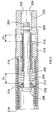
- a handle assembly for a power tool for example a hammer or drill including a hammer action, includes a first substantially tubular body portion 210 which contains a first biasing element, first spring 212.
- First spring 212 is retained at one end by an end portion 214 of first body 210 and at the other end by second body portion 216 which is slidably mounted within first body portion 210.
- Second body portion 216 contains a second biasing element, second spring 218, which is retained at one end by end portion 220 of second body portion 216.
- the other end of second spring 218 is retained by third body portion 222.
- the biasing coefficient, or spring constant, of the first spring 212 is less than that of the second spring 218. This means that the first spring 212 is softer, and therefore more easily compressed, than the second spring 218.
- the first, second and third body portions 210, 216 and 222, and first and second springs, 212 and 218, are all mounted coaxially on threaded bolt 224 and retained thereon at one end by head portion 226 of bolt 224 and at the other end by nut 228.
- the nut 228 is prevented from rotating within third body portion 222 by at least one flat surface 229 which engages one of the faces of nut 228.
- any rotation of bolt 224 will cause nut 228 to travel along the threaded portion of bolt 224. If bolt 224 is rotated such that nut 228 is caused to move towards head 226 the first and second springs 212 and 218 become more compressed. This has the effect of appearing to the user to increase the rigidity of the damping mechanism thereby transferring more vibrations to the handle. This may be desirable in some situations where a very hard substance is being drilled into.
- the biasing coefficient of the combined effect of the coaxially mounted springs, with a movable intermediate second body portion 216 between them, is calculated as the springs working in parallel. This is as opposed to the pair a springs acting in series as seen in the prior art DE 10036078.
- the spring constant for an assembly when both springs are acting (K total ) is calculated from the spring constant of the first spring 212 (K soft ) and the spring constant of the second spring (K hard ) as follows:
- First body portion 214 is connected to, or formed as part of, the housing of the power tool in which the assembly is contained.
- the third body portion 222 is connected to, or formed as part of, the handle of the same power tool. When in use the power tool is pressed against a surface such that the hammer action of the power tool is activated. The assembly allows for limited movement of the handle relative to the housing of the power tool.
- the second and third body portions 216 and 222 slide within the first body portion 210, and these movements are biased by the first and second springs 212 and 218.
- the assembly as shown in Figure 3 is in a first position in which the first and second springs 212 and 218 are fully extended as bound by the constraints of nut 228 and bolt 224.
- the third body portion 222 moves within first body portion 210 in a direction towards end portion 214 the softer spring 212 becomes compressed more rapidly than the second and harder spring 218.
- the distance D 1 which extends from end portion 220 to rubber washer 230, decreases at a faster rate than the distance D 2 .
- the rubber washer 230 engages end portion 220 of second body portion 216. Because washer 230 is made of rubber, or another similar resilient material, the impact of end portion 220 is slightly softened.
- biasing means may be used in alternative to the helical springs described above, such as leaf springs or torsion springs.
Applications Claiming Priority (2)
| Application Number | Priority Date | Filing Date | Title |
|---|---|---|---|
| GB0412619A GB2414702A (en) | 2004-06-04 | 2004-06-04 | Vibration Reduction Apparatus for Power Tool |
| GB0412619 | 2004-06-05 |
Publications (2)
| Publication Number | Publication Date |
|---|---|
| EP1602450A2 true EP1602450A2 (de) | 2005-12-07 |
| EP1602450A3 EP1602450A3 (de) | 2006-06-07 |
Family
ID=32696747
Family Applications (1)
| Application Number | Title | Priority Date | Filing Date |
|---|---|---|---|
| EP05012102A Withdrawn EP1602450A3 (de) | 2004-06-04 | 2005-06-06 | Vorrichtung zur Reduktion der Schwingungen eines kraftangetriebenen Werkzeugs und Kraftwerkzeug mit einer solchen Vorrichtung |
Country Status (3)
| Country | Link |
|---|---|
| US (1) | US7322428B2 (de) |
| EP (1) | EP1602450A3 (de) |
| GB (1) | GB2414702A (de) |
Cited By (3)
| Publication number | Priority date | Publication date | Assignee | Title |
|---|---|---|---|---|
| GB2419564A (en) * | 2004-10-22 | 2006-05-03 | Bosch Gmbh Robert | Hand held power tool with vibration-damped pistol grip |
| EP2551060A1 (de) * | 2011-07-26 | 2013-01-30 | Black & Decker Inc. | Bohrhammer |
| WO2017108317A1 (de) * | 2015-12-22 | 2017-06-29 | Robert Bosch Gmbh | Handwerkzeugmaschine |
Families Citing this family (29)
| Publication number | Priority date | Publication date | Assignee | Title |
|---|---|---|---|---|
| GB2407790A (en) * | 2003-11-04 | 2005-05-11 | Black & Decker Inc | Vibration reduction apparatus for a power tool |
| GB2407791A (en) * | 2003-11-04 | 2005-05-11 | Black & Decker Inc | Vibration reduction apparatus for a power tool |
| GB2407789A (en) * | 2003-11-04 | 2005-05-11 | Black & Decker Inc | Vibration reduction apparatus for a power tool |
| DE102004040886A1 (de) * | 2004-08-24 | 2006-03-02 | Volkswagen Ag | Bedienvorrichtung für ein Kraftfahrzeug |
| JP4647957B2 (ja) * | 2004-08-27 | 2011-03-09 | 株式会社マキタ | 作業工具 |
| JP4626574B2 (ja) * | 2006-06-16 | 2011-02-09 | 日立工機株式会社 | 電動工具 |
| DE102007012312A1 (de) * | 2007-03-14 | 2008-09-18 | Robert Bosch Gmbh | Handgriff |
| KR100850962B1 (ko) * | 2007-04-24 | 2008-08-08 | 엘지전자 주식회사 | 댐핑 조절 다리 및 이를 구비한 냉장고 |
| CN100475455C (zh) * | 2007-06-22 | 2009-04-08 | 浙江大学 | 具有减振的电锤工具手柄 |
| DE102007000837A1 (de) * | 2007-10-09 | 2009-04-16 | Hilti Aktiengesellschaft | Handwerkzeugmaschine mit Schwingungsausgleichsmasse |
| GB0801311D0 (en) * | 2008-01-24 | 2008-03-05 | Black & Decker Inc | Mounting assembly for handle for power tool |
| DE102008000625A1 (de) * | 2008-03-12 | 2009-09-17 | Robert Bosch Gmbh | Handwerkzeugmaschine |
| EP2119537A1 (de) * | 2008-05-17 | 2009-11-18 | Metabowerke GmbH | Elektrohandwerkzeuggerät |
| DE102008001957A1 (de) * | 2008-05-26 | 2009-12-03 | Robert Bosch Gmbh | Bohr- und/oder Meißelhammer |
| US8240394B2 (en) * | 2008-12-09 | 2012-08-14 | Sp Air Kabushiki Kaisha | Hammer with vibration reduction mechanism |
| GB2472997A (en) * | 2009-08-26 | 2011-03-02 | Black & Decker Inc | Hammer drill with vibration damping means in handle |
| US8196675B2 (en) * | 2010-03-24 | 2012-06-12 | Sing Hua Industrial Co., Ltd. | Impact hammer with pre-pressing damping and buffering effect |
| DE102011007725A1 (de) * | 2011-04-20 | 2012-10-25 | Hilti Aktiengesellschaft | Handwerkzeugmaschine und Tilger |
| WO2013116680A1 (en) * | 2012-02-03 | 2013-08-08 | Milwaukee Electric Tool Corporation | Rotary hammer |
| US9849577B2 (en) * | 2012-02-03 | 2017-12-26 | Milwaukee Electric Tool Corporation | Rotary hammer |
| US8966773B2 (en) | 2012-07-06 | 2015-03-03 | Techtronic Power Tools Technology Limited | Power tool including an anti-vibration handle |
| DE202012006747U1 (de) * | 2012-07-13 | 2013-10-16 | Illinois Tool Works, Inc. | Motorisch angetriebenes Handwerkzeug |
| JP2016140934A (ja) * | 2015-01-30 | 2016-08-08 | 日立工機株式会社 | 動力工具 |
| US10053873B2 (en) * | 2016-08-17 | 2018-08-21 | M-B-W, Inc. | Handle assemblies with vibration dampening assemblies for concrete finishing machines |
| US11845168B2 (en) * | 2019-11-01 | 2023-12-19 | Makita Corporation | Reciprocating tool |
| JP2022119301A (ja) * | 2021-02-04 | 2022-08-17 | 株式会社マキタ | 打撃工具 |
| JP2022128006A (ja) * | 2021-02-22 | 2022-09-01 | 株式会社マキタ | 打撃工具 |
| WO2022236800A1 (en) * | 2021-05-14 | 2022-11-17 | Techtronic Cordless Gp | A handle for use with a power tool |
| JP7454311B1 (ja) | 2023-10-02 | 2024-03-22 | アピュアン株式会社 | エアー式衝撃工具 |
Citations (2)
| Publication number | Priority date | Publication date | Assignee | Title |
|---|---|---|---|---|
| GB2086005A (en) * | 1980-10-13 | 1982-05-06 | Minamidate Makoto | Vibration Damping Handle |
| FR2581337A1 (fr) * | 1985-05-02 | 1986-11-07 | Sorelem | Perfectionnements aux brise-beton |
Family Cites Families (60)
| Publication number | Priority date | Publication date | Assignee | Title |
|---|---|---|---|---|
| US644014A (en) | 1899-01-24 | 1900-02-20 | Manetho C Jackson | Power-hammer. |
| US1358486A (en) | 1920-04-24 | 1920-11-09 | Ingersoll Rand Co | Handle for percussive tools |
| US1597245A (en) | 1923-12-28 | 1926-08-24 | Ingersoll Rand Co | Handle for percussive tools |
| US1573458A (en) * | 1925-03-13 | 1926-02-16 | Ingersoll Rand Co | Cushion handle |
| US1711688A (en) * | 1925-12-08 | 1929-05-07 | Chicago Pneumatic Tool Co | Drill and manual support therefor |
| US1644030A (en) * | 1926-08-04 | 1927-10-04 | Ingersoll Rand Co | Handle for rock drills |
| AT122752B (de) | 1930-01-10 | 1931-05-11 | Ernst Ing Elster | Abfederung der Haltevorrichtung von Werzeugen mit hin und her gehender Arbeitsbewegung. |
| US2290256A (en) * | 1940-11-04 | 1942-07-21 | Eugene H Souter | Pneumatic tool |
| US2349341A (en) * | 1942-11-13 | 1944-05-23 | Josef A Disse | Riveting device |
| BE515037A (de) | 1951-10-23 | |||
| BE537958A (de) | 1954-05-07 | |||
| GB1152119A (en) | 1966-11-29 | 1969-05-14 | Atlas Copco Ab | Improvements in Recoil Vibration Damped Percussive Machine |
| CS149009B1 (de) | 1971-02-01 | 1973-05-24 | ||
| US3849883A (en) | 1974-01-02 | 1974-11-26 | Outboard Marine Corp | Chain saw |
| US4138812A (en) | 1977-10-14 | 1979-02-13 | Mcculloch Corporation | Vibration isolation system for chain saw structures |
| US4217677A (en) * | 1978-03-13 | 1980-08-19 | Kure Tekko Company Ltd. | Apparatus for preventing transmission of vibration of a vibration machine |
| JPS54127080A (en) | 1978-03-25 | 1979-10-02 | Makoto Nandate | Vibration isolation device in handle of machine in which vibration is formed |
| SE420058B (sv) | 1980-01-24 | 1981-09-14 | Atlas Copco Ab | Svengningsdempande anordning vid handhallna slaende maskiner |
| JPS6044530B2 (ja) | 1980-03-13 | 1985-10-04 | 正治 窪川 | 振動機器の防振緩衝把手 |
| JPS5834271B2 (ja) | 1980-07-18 | 1983-07-26 | 日立工機株式会社 | 振動工具のハンドル防振装置 |
| DE3122979A1 (de) | 1981-06-10 | 1983-01-05 | Hilti AG, 9494 Schaan | Bohr- oder meisselhammer |
| FR2516891A1 (fr) | 1981-11-25 | 1983-05-27 | Aerospatiale | Rotor pour giravions, a articulations integrees dans le pied de pale |
| DE3312195A1 (de) | 1983-04-02 | 1984-10-11 | Wacker-Werke Gmbh & Co Kg, 8077 Reichertshofen | Handgefuehrter schlag- und bohrhammer |
| DE3410669A1 (de) | 1984-03-23 | 1985-10-24 | Metabowerke GmbH & Co, 7440 Nürtingen | Daempfungselement und dessen einbau in ein motorisch angetriebenes handwerkzeug |
| SE442963B (sv) | 1984-05-07 | 1986-02-10 | Atlas Copco Ab | Vibrationsisolerande handtag |
| SU1269989A1 (ru) * | 1984-10-09 | 1986-11-15 | Сибирский Ордена Трудового Красного Знамени Автомобильно-Дорожный Институт Им.В.В.Куйбышева | Машина ударного действи |
| DE3447401A1 (de) | 1984-12-24 | 1986-07-03 | Wacker-Werke Gmbh & Co Kg, 8077 Reichertshofen | Hammer mit schutzhaube |
| DE3521808A1 (de) | 1985-06-19 | 1987-01-02 | Hilti Ag | Schwingungen erzeugendes handwerkzeug |
| JP2534318B2 (ja) | 1988-04-30 | 1996-09-11 | 日立工機株式会社 | 動力工具の防振ハンドル |
| US4905772A (en) | 1988-09-01 | 1990-03-06 | Honsa Thomas W | Rotary power tool with vibration damping |
| DE3839207A1 (de) | 1988-11-19 | 1990-05-23 | Hilti Ag | Tragbares handgeraet mit schlagwerk |
| SU1829259A1 (ru) * | 1988-12-21 | 1996-02-27 | Институт Горного Дела Со Ан Ссср | Пневматический молоток |
| JP2931025B2 (ja) | 1989-03-18 | 1999-08-09 | アンドレアス シュティール | 抗振動エレメントによって結合された握り部を有するモータ駆動手操作作業機 |
| GB8907410D0 (en) | 1989-04-01 | 1989-05-17 | Macdonald Pneumatics | Paving breakers and supports therefor |
| DE4011124A1 (de) | 1990-04-06 | 1991-10-10 | Metabowerke Kg | Vibrationsgedaempfter handgriff |
| SE466093B (sv) | 1990-05-04 | 1991-12-16 | Atlas Copco Tools Ab | Vibrationsdaempad handhaallen rotationsslipmaskin |
| DE4022674A1 (de) * | 1990-07-17 | 1992-01-23 | Hilti Ag | Pulverkraftbetriebenes setzgeraet |
| DE4124574A1 (de) | 1991-07-24 | 1993-01-28 | Wolf Woco & Co Franz J | Griffisolierung |
| SE469549B (sv) * | 1991-11-04 | 1993-07-26 | Atlas Copco Tools Ab | Vibrationsdaempande organ foer ett handhaallet verktyg |
| US5213167A (en) | 1992-06-16 | 1993-05-25 | Ingersoll-Rand Company | Apparatus for reducing vibration transmission in hand-held tool |
| JPH08126975A (ja) | 1994-10-28 | 1996-05-21 | Hitachi Koki Co Ltd | 電気ハンマの防振ハンドル |
| US5363736A (en) * | 1994-01-05 | 1994-11-15 | Huang Kuang Wu | Semi-automatic anchor shooter |
| US5607343A (en) | 1994-08-22 | 1997-03-04 | Ryobi North America | Sander vibration isolator |
| DE19503526A1 (de) | 1995-02-03 | 1996-08-08 | Bosch Gmbh Robert | Bohr- und/oder Schlaghammer mit abnehmbarem vibrationsgedämpften Handgriff sowie vibrationsgedämpfte Handgriffanordnung für einen Bohr- und/oder Schlaghammer |
| US5697456A (en) | 1995-04-10 | 1997-12-16 | Milwaukee Electric Tool Corp. | Power tool with vibration isolated handle |
| DE19631517A1 (de) | 1996-08-03 | 1998-02-05 | Wacker Werke Kg | Von einem Elektromotor angetriebenes, an Einphasenwechselstrom anschließbares, drehzahlvariables, handgehaltenes Elektrowerkzeug |
| DE29700003U1 (de) | 1997-01-02 | 1997-02-27 | Wacker Werke Kg | Aufbruch- und/oder Bohrhammer |
| US6189874B1 (en) | 1997-07-01 | 2001-02-20 | Lord Corporation | X-configuration engine mounting |
| USH1811H (en) | 1997-12-16 | 1999-11-02 | Rescigno; Gerald R. | Apparatus and method for reducing low frequency vibrations in power tools |
| WO2000047862A1 (en) | 1999-02-10 | 2000-08-17 | Anglo Operations Limited | Rock drill handle |
| DE19925281B4 (de) | 1999-06-02 | 2014-10-02 | Andreas Stihl Ag & Co. | Handgeführtes Arbeitsgerät, insbesondere Heckenschere mit vibrationsgedämpften Handgriffen |
| DE19943629B4 (de) | 1999-09-11 | 2015-04-09 | Andreas Stihl Ag & Co. | Handgeführtes Arbeitsgerät |
| DE10005080C1 (de) | 2000-02-04 | 2001-08-02 | Bosch Gmbh Robert | Handwerkzeugmaschine mit zumindest einem Handgriff und wenigstens einem elastischen, schwingungsdämpfenden Element |
| DE10034768A1 (de) | 2000-07-18 | 2002-02-07 | Bosch Gmbh Robert | Elektrokombihammer |
| DE10036078B4 (de) | 2000-07-25 | 2007-04-05 | Robert Bosch Gmbh | Handwerkzeugmaschine mit einem Handgriff und einer Isoliervorrichtung |
| DE10130088C2 (de) | 2001-06-21 | 2003-10-16 | Hilti Ag | Schlagendes Elektrohandwerkzeuggerät mit aktiver Vibrationsdämpfung |
| DE10130548B4 (de) | 2001-06-25 | 2008-01-03 | Robert Bosch Gmbh | Zusatzhandgriff |
| JP3966703B2 (ja) * | 2001-09-17 | 2007-08-29 | Ntn株式会社 | 回転伝達装置 |
| ITMI20020010A1 (it) | 2002-01-08 | 2003-07-08 | Top Glass Spa | Elemento ad elevata resistenza meccanica ed elevato grado di smorzamento di vibrazioni e procedimento per la sua realizzazione |
| EP1882560B1 (de) | 2003-09-10 | 2011-06-08 | Makita Corporation | Schwingungsfreier Griff |
-
2004
- 2004-06-04 GB GB0412619A patent/GB2414702A/en not_active Withdrawn
-
2005
- 2005-06-06 EP EP05012102A patent/EP1602450A3/de not_active Withdrawn
- 2005-06-06 US US11/146,181 patent/US7322428B2/en not_active Expired - Fee Related
Patent Citations (2)
| Publication number | Priority date | Publication date | Assignee | Title |
|---|---|---|---|---|
| GB2086005A (en) * | 1980-10-13 | 1982-05-06 | Minamidate Makoto | Vibration Damping Handle |
| FR2581337A1 (fr) * | 1985-05-02 | 1986-11-07 | Sorelem | Perfectionnements aux brise-beton |
Non-Patent Citations (2)
| Title |
|---|
| DATABASE WPI Section PQ, Week 198726 Derwent Publications Ltd., London, GB; Class P62, AN 1987-184120 XP002378790 -& SU 1 269 989 A (SIBE CAR ROAD INST) 15 November 1986 (1986-11-15) * |
| DATABASE WPI Section PQ, Week 199641 Derwent Publications Ltd., London, GB; Class P62, AN 1996-411317 XP002378789 -& SU 1 829 259 A1 (AS SIBE MINING INST) 27 February 1996 (1996-02-27) * |
Cited By (5)
| Publication number | Priority date | Publication date | Assignee | Title |
|---|---|---|---|---|
| GB2419564A (en) * | 2004-10-22 | 2006-05-03 | Bosch Gmbh Robert | Hand held power tool with vibration-damped pistol grip |
| GB2419564B (en) * | 2004-10-22 | 2007-09-05 | Bosch Gmbh Robert | Hand tool machine with vibration-damped pistol grip |
| US8069930B2 (en) | 2004-10-22 | 2011-12-06 | Robert Bosch Gmbh | Hand power tool with vibration-damped pistol grip |
| EP2551060A1 (de) * | 2011-07-26 | 2013-01-30 | Black & Decker Inc. | Bohrhammer |
| WO2017108317A1 (de) * | 2015-12-22 | 2017-06-29 | Robert Bosch Gmbh | Handwerkzeugmaschine |
Also Published As
| Publication number | Publication date |
|---|---|
| US7322428B2 (en) | 2008-01-29 |
| EP1602450A3 (de) | 2006-06-07 |
| US20050284646A1 (en) | 2005-12-29 |
| GB0412619D0 (en) | 2004-07-07 |
| GB2414702A (en) | 2005-12-07 |
Similar Documents
| Publication | Publication Date | Title |
|---|---|---|
| EP1602450A2 (de) | Vorrichtung zur Reduktion der Schwingungen eines kraftangetriebenen Werkzeugs und Kraftwerkzeug mit einer solchen Vorrichtung | |
| EP1529603B1 (de) | Schwingungsdämpfungsvorrichtung für ein Elektrowerkzeug und Elektrowerkzeug mit einer solchen Vorrichtung | |
| US7789168B2 (en) | Vibration reduction apparatus for power tool and power tool incorporating such apparatus | |
| EP1710052B1 (de) | Schlagwerkzeug mit einem Schwingungsdämpfungsmittel | |
| US7320369B2 (en) | Vibration reduction apparatus for power tool and power tool incorporating such apparatus | |
| US7472760B2 (en) | Vibration reduction apparatus for power tool and power tool incorporating such apparatus | |
| GB2413612A (en) | Vibration reduction apparatus for power tool and power tool incorporating such apparatus | |
| JP5100171B2 (ja) | 衝撃式作業工具 | |
| GB2431133A (en) | A power tool with vibration reduction apparatus | |
| AU2006200540B2 (en) | Vibration reduction apparatus for power tool and power tool incorporating such apparatus |
Legal Events
| Date | Code | Title | Description |
|---|---|---|---|
| PUAI | Public reference made under article 153(3) epc to a published international application that has entered the european phase |
Free format text: ORIGINAL CODE: 0009012 |
|
| AK | Designated contracting states |
Kind code of ref document: A2 Designated state(s): AT BE BG CH CY CZ DE DK EE ES FI FR GB GR HU IE IS IT LI LT LU MC NL PL PT RO SE SI SK TR |
|
| AX | Request for extension of the european patent |
Extension state: AL BA HR LV MK YU |
|
| PUAL | Search report despatched |
Free format text: ORIGINAL CODE: 0009013 |
|
| AK | Designated contracting states |
Kind code of ref document: A3 Designated state(s): AT BE BG CH CY CZ DE DK EE ES FI FR GB GR HU IE IS IT LI LT LU MC NL PL PT RO SE SI SK TR |
|
| AX | Request for extension of the european patent |
Extension state: AL BA HR LV MK YU |
|
| AKX | Designation fees paid |
Designated state(s): AT BE BG CH CY CZ DE DK EE ES FI FR GB GR HU IE IS IT LI LT LU MC NL PL PT RO SE SI SK TR |
|
| STAA | Information on the status of an ep patent application or granted ep patent |
Free format text: STATUS: THE APPLICATION IS DEEMED TO BE WITHDRAWN |
|
| 18D | Application deemed to be withdrawn |
Effective date: 20061208 |