EP1602450A2 - Vibration reduction apparatus for power tool and power tool incorporating such apparatus - Google Patents
Vibration reduction apparatus for power tool and power tool incorporating such apparatus Download PDFInfo
- Publication number
- EP1602450A2 EP1602450A2 EP05012102A EP05012102A EP1602450A2 EP 1602450 A2 EP1602450 A2 EP 1602450A2 EP 05012102 A EP05012102 A EP 05012102A EP 05012102 A EP05012102 A EP 05012102A EP 1602450 A2 EP1602450 A2 EP 1602450A2
- Authority
- EP
- European Patent Office
- Prior art keywords
- handle
- body portion
- biasing
- spring
- power tool
- Prior art date
- Legal status (The legal status is an assumption and is not a legal conclusion. Google has not performed a legal analysis and makes no representation as to the accuracy of the status listed.)
- Withdrawn
Links
Images


Classifications
-
- B—PERFORMING OPERATIONS; TRANSPORTING
- B25—HAND TOOLS; PORTABLE POWER-DRIVEN TOOLS; MANIPULATORS
- B25D—PERCUSSIVE TOOLS
- B25D17/00—Details of, or accessories for, portable power-driven percussive tools
- B25D17/04—Handles; Handle mountings
- B25D17/043—Handles resiliently mounted relative to the hammer housing
-
- B—PERFORMING OPERATIONS; TRANSPORTING
- B25—HAND TOOLS; PORTABLE POWER-DRIVEN TOOLS; MANIPULATORS
- B25D—PERCUSSIVE TOOLS
- B25D2250/00—General details of portable percussive tools; Components used in portable percussive tools
- B25D2250/005—Adjustable tool components; Adjustable parameters
-
- B—PERFORMING OPERATIONS; TRANSPORTING
- B25—HAND TOOLS; PORTABLE POWER-DRIVEN TOOLS; MANIPULATORS
- B25D—PERCUSSIVE TOOLS
- B25D2250/00—General details of portable percussive tools; Components used in portable percussive tools
- B25D2250/371—Use of springs
Definitions
- the present invention relates to vibration reduction apparatus for power tools and to power tools incorporating such apparatus.
- the invention relates particularly, but not exclusively, to vibration reduction apparatus for power hammers, and to hammers incorporating such apparatus.
- the prior art demolition hammer comprises an electric motor 2, a gear arrangement and a piston drive arrangement which are housed within a metal gear housing 5 surrounded by a plastic housing 4 .
- a rear handle housing incorporating a rear handle 6 and a trigger switch arrangement 8 is fitted to the rear of the housings 4, 5.
- a cable (not shown) extends through a cable guide 10 and connects the motor to an external electricity supply. When the cable is connected to the electricity supply and the trigger switch arrangement 8 is depressed, the motor 2 is actuated to rotationally drive the armature of the motor.
- a radial fan 14 is fitted at one end of the armature and a pinion is formed at the opposite end of the armature so that when the motor is actuated the armature rotatingly drives the fan 14 and the pinion.
- the metal gear housing 5 is made from magnesium with steel inserts and rigidly supports the components housed within it.
- the motor pinion rotatingly drives a first gear wheel of an intermediate gear arrangement which is rotatably mounted on a spindle, which spindle is mounted in an insert to the gear housing 5.
- the intermediate gear has a second gear wheel which rotatingly drives a drive gear.
- the drive gear is non-rotatably mounted on a drive spindle mounted within the gear housing 5.
- a crank plate 30 is non-rotatably mounted at the end of the drive spindle remote from the drive gear, the crank plate being formed with an eccentric bore for housing an eccentric crank pin 32.
- the crank pin 32 extends from the crank plate into a bore at the rearward end of a crank arm 34 so that the crank arm can pivot about the crank pin 32.
- the opposite forward end of the crank arm 34 is formed with a bore through which extends a trunnion pin 36 so that the crank arm 34 can pivot about the trunnion pin 36.
- the trunnion pin 36 is fitted to the rear of a piston 38 by fitting the ends of the trunnion pin 36 into receiving bores formed in a pair of opposing arms which extend to the rear of the piston 38.
- the piston is reciprocally mounted in cylindrical hollow spindle 40 so that it can reciprocate within the hollow spindle.
- An O-ring seal 42 is fitted in an annular recess formed in the periphery of the piston 38 so as to form an airtight seal between the piston 38 and the internal surface of the hollow spindle 40.
- the armature pinion rotatingly drives the intermediate gear arrangement via the first gear wheel and the second gear wheel of the intermediate gear arrangement rotatingly drives the drive spindle via the drive gear.
- the drive spindle rotatingly drives the crank plate 30 and the crank arm arrangement comprising the crank pin 32, and the crank arm 34 and the trunnion pin 36 convert the rotational drive from the crank plate 30 to a reciprocating drive to the piston 38.
- the piston 38 is reciprocatingly driven back and forth along the hollow spindle 40 when the motor is actuated by a user depressing the trigger switch 8.
- the spindle 40 is mounted in magnesium casing 42 from the forward end until an annular rearward facing shoulder (not shown) on the exterior of the spindle abuts against a forward facing annular shoulder (not shown) formed from a set of ribs in the interior of the magnesium casing 42.
- the ribs enable air in the chamber surrounding the spindle 40 to circulate freely in the region between a ram 58 and a beat piece 64.
- An increased diameter portion on the exterior of the spindle fits closely within a reduced diameter portion on the interior of the magnesium casing 42. Rearwardly of the increased diameter portion and the reduced diameter portion an annular chamber is formed between the external surface of the spindle 40 and the internal surface of the magnesium casing 42. This chamber is open at its forward and rearward ends.
- the chamber communicates via the spaces between the ribs in the magnesium casing with a volume of air between the ram 58 and the beat piece 64.
- the chamber communicates via the spaces between the ribs 7 and the recess of the gear casing 5 with a volume of air in the gear casing 5.
- the volume of air in the gear casing 5 communicates with the air outside of the hammer via a narrow channel 9 and a filter 11.
- the air pressure within the hammer which changes due to changes in the temperature of the hammer, is thus equalised with the air pressure outside of the hammer.
- the filter 11 also keeps the air within the hammer gear casing 5 relatively clean and dust free.
- the ram 58 is located within the hollow spindle 40 forwardly of the piston 38 so that it can also reciprocate within the hollow spindle 40.
- An O-ring seal 60 is located in a recess formed around the periphery of the ram 58 so as to form an airtight seal between the ram 58 and the spindle 40.
- a closed air cushion is formed between the forward face of the piston 38 and the rearward face of the ram 58. Reciprocation of the piston 38 thus reciprocatingly drives the ram 58 via the closed air cushion.
- hammer drills of this type suffer from the drawback that the hammer action generates significant vibrations, which can be harmful to users of the apparatus, and can cause damage to the apparatus itself.
- a power tool 100 has a handle 102 which is connected to a housing 104 at one end by a pivot 106 and at the other end by a damping mechanism 108.
- the damping mechanism 108 has a first spring 110 which is located within two apertures, 112 and 114, respectively set into the handle 102 and housing 104.
- First spring 110 can be compressed so that handle 102 comes into contact with housing 104 by closing space 116.
- Damping mechanism 108 also has a second spring 120, which is stiffer than first spring 110.
- Second spring 120 at one end engages handle 102 and at its other end engages a cup shaped device 122.
- Cup 122 prevents spring 120 extending beyond the position shown in Figure 2 by virtue of a rivet 124 which is at one end fixed to cup 122 and adjacent the other end slidably located within aperture 126.
- power tool 100 is pushed by a user in direction 128 which causes handle 102 to move towards housing 104. This in turn causes the compression of first spring 110 and dampens vibrations which are caused by the hammer action of the power tool.
- cup 122 also moves towards housing 104.
- cup 122 becomes engaged with housing 104 and further movement of handle 102 towards housing 104 is opposed by both springs 110 and 120. Further movement of the handle is possible against the action of both springs 110 and 120 until gap 116 is closed at which point movement of the handle 102 is no longer dampened relative to the movement of the housing and all vibrations within the housing 104 are directly passed to the handle 102.
- Dampening devices of this type suffer from the disadvantage that the transition from the dampening of a single spring to both springs is abrupt, causing additional vibration in the handle which must be absorbed by the user.
- At least one said first and/or second biasing element comprises at least one leaf spring.
- At least one first biasing element comprises at least one first helical spring and at least one second biasing element comprises at least one second helical spring.
- the damping device is significantly more compact than the damping devices of the prior art.
- the effective spring constant K total of the pair of springs in use together is calculated by adding the spring constants K soft , K hard of the individual springs in parallel as opposed to in series, as is the case in the prior art DE10036078. For example:
- At least one said elongate member comprises at least one helical thread and is adapted to receive at least one respective cooperating threaded nut.
- the advantage is provided that the nut and bolt can be used to adjust the tension in the springs and the amount of movement allowed by the damping mechanism.
- the assembly may further comprise at least one stop for preventing further compression of at least one said first biasing member between said second and said third handle positions.
- At least one said stop may comprise at least one annular member and may further comprise at least one resilient material.
- the assembly may further comprise at least one said first and second biasing element connected at a first end of said handle and at least one said first and second biasing element connected at a second end of said handle.
- a power tool comprising:-
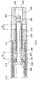
- a handle assembly for a power tool for example a hammer or drill including a hammer action, includes a first substantially tubular body portion 210 which contains a first biasing element, first spring 212.
- First spring 212 is retained at one end by an end portion 214 of first body 210 and at the other end by second body portion 216 which is slidably mounted within first body portion 210.
- Second body portion 216 contains a second biasing element, second spring 218, which is retained at one end by end portion 220 of second body portion 216.
- the other end of second spring 218 is retained by third body portion 222.
- the biasing coefficient, or spring constant, of the first spring 212 is less than that of the second spring 218. This means that the first spring 212 is softer, and therefore more easily compressed, than the second spring 218.
- the first, second and third body portions 210, 216 and 222, and first and second springs, 212 and 218, are all mounted coaxially on threaded bolt 224 and retained thereon at one end by head portion 226 of bolt 224 and at the other end by nut 228.
- the nut 228 is prevented from rotating within third body portion 222 by at least one flat surface 229 which engages one of the faces of nut 228.
- any rotation of bolt 224 will cause nut 228 to travel along the threaded portion of bolt 224. If bolt 224 is rotated such that nut 228 is caused to move towards head 226 the first and second springs 212 and 218 become more compressed. This has the effect of appearing to the user to increase the rigidity of the damping mechanism thereby transferring more vibrations to the handle. This may be desirable in some situations where a very hard substance is being drilled into.
- the biasing coefficient of the combined effect of the coaxially mounted springs, with a movable intermediate second body portion 216 between them, is calculated as the springs working in parallel. This is as opposed to the pair a springs acting in series as seen in the prior art DE 10036078.
- the spring constant for an assembly when both springs are acting (K total ) is calculated from the spring constant of the first spring 212 (K soft ) and the spring constant of the second spring (K hard ) as follows:
- First body portion 214 is connected to, or formed as part of, the housing of the power tool in which the assembly is contained.
- the third body portion 222 is connected to, or formed as part of, the handle of the same power tool. When in use the power tool is pressed against a surface such that the hammer action of the power tool is activated. The assembly allows for limited movement of the handle relative to the housing of the power tool.
- the second and third body portions 216 and 222 slide within the first body portion 210, and these movements are biased by the first and second springs 212 and 218.
- the assembly as shown in Figure 3 is in a first position in which the first and second springs 212 and 218 are fully extended as bound by the constraints of nut 228 and bolt 224.
- the third body portion 222 moves within first body portion 210 in a direction towards end portion 214 the softer spring 212 becomes compressed more rapidly than the second and harder spring 218.
- the distance D 1 which extends from end portion 220 to rubber washer 230, decreases at a faster rate than the distance D 2 .
- the rubber washer 230 engages end portion 220 of second body portion 216. Because washer 230 is made of rubber, or another similar resilient material, the impact of end portion 220 is slightly softened.
- biasing means may be used in alternative to the helical springs described above, such as leaf springs or torsion springs.
Abstract
Description
- The present invention relates to vibration reduction apparatus for power tools and to power tools incorporating such apparatus. The invention relates particularly, but not exclusively, to vibration reduction apparatus for power hammers, and to hammers incorporating such apparatus.
- Electrically driven hammers are known in which a driving member in the form of a flying mass is reciprocally driven by means of a piston, and impact of the flying mass against the end of the piston cylinder imparts a hammer action to a bit of the hammer. Such an arrangement is disclosed in European patent application EP1252976 and is shown in Figure 1.
- Referring in detail to Figure 1, the prior art demolition hammer comprises an electric motor 2, a gear arrangement and a piston drive arrangement which are housed within a
metal gear housing 5 surrounded by aplastic housing 4. A rear handle housing incorporating a rear handle 6 and a trigger switch arrangement 8 is fitted to the rear of thehousings cable guide 10 and connects the motor to an external electricity supply. When the cable is connected to the electricity supply and the trigger switch arrangement 8 is depressed, the motor 2 is actuated to rotationally drive the armature of the motor. A radial fan 14 is fitted at one end of the armature and a pinion is formed at the opposite end of the armature so that when the motor is actuated the armature rotatingly drives the fan 14 and the pinion. Themetal gear housing 5 is made from magnesium with steel inserts and rigidly supports the components housed within it. - The motor pinion rotatingly drives a first gear wheel of an intermediate gear arrangement which is rotatably mounted on a spindle, which spindle is mounted in an insert to the
gear housing 5. The intermediate gear has a second gear wheel which rotatingly drives a drive gear. The drive gear is non-rotatably mounted on a drive spindle mounted within thegear housing 5. Acrank plate 30 is non-rotatably mounted at the end of the drive spindle remote from the drive gear, the crank plate being formed with an eccentric bore for housing aneccentric crank pin 32. Thecrank pin 32 extends from the crank plate into a bore at the rearward end of acrank arm 34 so that the crank arm can pivot about thecrank pin 32. The opposite forward end of thecrank arm 34 is formed with a bore through which extends atrunnion pin 36 so that thecrank arm 34 can pivot about thetrunnion pin 36. Thetrunnion pin 36 is fitted to the rear of apiston 38 by fitting the ends of thetrunnion pin 36 into receiving bores formed in a pair of opposing arms which extend to the rear of thepiston 38. The piston is reciprocally mounted in cylindricalhollow spindle 40 so that it can reciprocate within the hollow spindle. An O-ring seal 42 is fitted in an annular recess formed in the periphery of thepiston 38 so as to form an airtight seal between thepiston 38 and the internal surface of thehollow spindle 40. - When the motor 2 is actuated, the armature pinion rotatingly drives the intermediate gear arrangement via the first gear wheel and the second gear wheel of the intermediate gear arrangement rotatingly drives the drive spindle via the drive gear. The drive spindle rotatingly drives the
crank plate 30 and the crank arm arrangement comprising thecrank pin 32, and thecrank arm 34 and thetrunnion pin 36 convert the rotational drive from thecrank plate 30 to a reciprocating drive to thepiston 38. In this way thepiston 38 is reciprocatingly driven back and forth along thehollow spindle 40 when the motor is actuated by a user depressing the trigger switch 8. - The
spindle 40 is mounted inmagnesium casing 42 from the forward end until an annular rearward facing shoulder (not shown) on the exterior of the spindle abuts against a forward facing annular shoulder (not shown) formed from a set of ribs in the interior of themagnesium casing 42. The ribs enable air in the chamber surrounding thespindle 40 to circulate freely in the region between aram 58 and abeat piece 64. An increased diameter portion on the exterior of the spindle fits closely within a reduced diameter portion on the interior of themagnesium casing 42. Rearwardly of the increased diameter portion and the reduced diameter portion an annular chamber is formed between the external surface of thespindle 40 and the internal surface of themagnesium casing 42. This chamber is open at its forward and rearward ends. At its forward end the chamber communicates via the spaces between the ribs in the magnesium casing with a volume of air between theram 58 and thebeat piece 64. At its rearward end the chamber communicates via the spaces between theribs 7 and the recess of thegear casing 5 with a volume of air in thegear casing 5. - The volume of air in the
gear casing 5 communicates with the air outside of the hammer via a narrow channel 9 and a filter 11. The air pressure within the hammer, which changes due to changes in the temperature of the hammer, is thus equalised with the air pressure outside of the hammer. The filter 11 also keeps the air within thehammer gear casing 5 relatively clean and dust free. - The
ram 58 is located within thehollow spindle 40 forwardly of thepiston 38 so that it can also reciprocate within thehollow spindle 40. An O-ring seal 60 is located in a recess formed around the periphery of theram 58 so as to form an airtight seal between theram 58 and thespindle 40. In the operating position of the ram 58 (shown in the upper half of Figure 1), with the ram located behindbores 62 in the spindle, a closed air cushion is formed between the forward face of thepiston 38 and the rearward face of theram 58. Reciprocation of thepiston 38 thus reciprocatingly drives theram 58 via the closed air cushion. When the hammer enters idle mode (i.e. when the hammer bit is removed from a work piece), theram 58 moves forwardly, past thebores 62 to the position shown in the bottom half of Figure 1. This vents the air cushion and so theram 58 is no longer reciprocatingly driven by thepiston 38 in idle mode, as is known to persons skilled in the art. - Known hammer drills of this type suffer from the drawback that the hammer action generates significant vibrations, which can be harmful to users of the apparatus, and can cause damage to the apparatus itself.
- Solutions to this problem have been proposed, for example, by including in devices of the type shown in Figure 1 compression springs between one or both of the ends of handle 6 and the body of the device. An example of such a device is described in German patent application DE 10036078. One of the embodiments disclosed in DE 10036078 is shown in Figure 2 of the present application, from which is can be seen that a
power tool 100 has ahandle 102 which is connected to ahousing 104 at one end by apivot 106 and at the other end by adamping mechanism 108. Thedamping mechanism 108 has afirst spring 110 which is located within two apertures, 112 and 114, respectively set into thehandle 102 andhousing 104.First spring 110 can be compressed so thathandle 102 comes into contact withhousing 104 byclosing space 116. -
Damping mechanism 108 also has asecond spring 120, which is stiffer thanfirst spring 110.Second spring 120 at one end engageshandle 102 and at its other end engages a cup shapeddevice 122.Cup 122 preventsspring 120 extending beyond the position shown in Figure 2 by virtue of arivet 124 which is at one end fixed tocup 122 and adjacent the other end slidably located withinaperture 126. - In
use power tool 100 is pushed by a user indirection 128 which causeshandle 102 to move towardshousing 104. This in turn causes the compression offirst spring 110 and dampens vibrations which are caused by the hammer action of the power tool. Ashandle 102 moves towardshousing 104cup 122 also moves towardshousing 104. Oncehandle 102 has moved through a distance indicated at 130,cup 122 becomes engaged withhousing 104 and further movement ofhandle 102 towardshousing 104 is opposed by bothsprings springs gap 116 is closed at which point movement of thehandle 102 is no longer dampened relative to the movement of the housing and all vibrations within thehousing 104 are directly passed to thehandle 102. - Dampening devices of this type suffer from the disadvantage that the transition from the dampening of a single spring to both springs is abrupt, causing additional vibration in the handle which must be absorbed by the user.
- Preferred embodiments of the present invention seek to overcome problems with the prior art.
- According to an aspect of the present invention there is provided a handle assembly for a power tool, the assembly comprising:-
- at least one handle adapted to be held by a user of the power tool and to be mounted to a housing of the power tool such that at least one said handle is capable of movement relative to the housing between a respective first handle position, a respective second handle position and a respective third handle position, all measured relative to said housing;
- at least one first biasing element for urging at least one said handle towards said first handle position therein, the or each said first biasing element having a first biasing coefficient; and
- at least one second biasing element for urging at least one said handle towards said first handle position, the or each said second biasing element having a second biasing coefficient, wherein said first biasing coefficient is less than said second biasing coefficient and wherein said first biasing element does not act on said handle between said second and third handle positions.
-
- By providing a handle assembly with a damping device in which the hard and soft springs initially act together over a distance between a first position and a second position and then, upon reaching the second position, only the harder spring acts, the advantage is provided that the transition from softer biasing of the handle during the initial movements to the stiffer biasing between the second and third positions is smoother. This causes significant and surprising reductions in the discomfort felt by the user when compared to the damping devices of the prior art.
- In a preferred embodiment at least one said first and/or second biasing element comprises at least one leaf spring.
- In another preferred embodiment at least one said first and/or second biasing element comprises at least one torsion spring.
- In a further preferred embodiment at least one first biasing element comprises at least one first helical spring and at least one second biasing element comprises at least one second helical spring.
- At least one said first helical spring may be mounted substantially coaxially with at least one said second helical spring.
- The assembly may further comprise at least one elongate member mounted substantially coaxially with at least one first biasing element and at least one second biasing element.
- By mounting the helical springs substantially coaxially, the advantage is provided that the damping device is significantly more compact than the damping devices of the prior art. Furthermore, by mounting the springs substantially coaxially the effective spring constant K total of the pair of springs in use together is calculated by adding the spring constants K soft , K hard of the individual springs in parallel as opposed to in series, as is the case in the prior art DE10036078. For example:

- In a preferred embodiment, at least one said elongate member comprises at least one helical thread and is adapted to receive at least one respective cooperating threaded nut.
- By mounting the two springs on a threaded nut and bolt, the advantage is provided that the nut and bolt can be used to adjust the tension in the springs and the amount of movement allowed by the damping mechanism.
- The assembly may further comprise at least one stop for preventing further compression of at least one said first biasing member between said second and said third handle positions.
- At least one said stop may comprise at least one annular member and may further comprise at least one resilient material.
- By providing a resilient stop the advantage is provided that the transition from the user of one biasing element to the use of both biasing elements is further dampened, thereby further reducing the vibrations experienced by the user of the power tool.
- The assembly may further comprise at least one first tubular body portion, at least one second body portion and at least one third body portion, wherein said first tubular body portion is adapted to receive said first biasing member, said second body portion is slidably received in said first body portion, said first tubular body portion is also adapted to receive said second biasing member and said third body portion is slidably received in said first body portion.
- By situating the springs and body portions within a tubular body portion the advantage is provided that the handle is constrained to move linearly relative to the housing thereby reducing the likelihood of non-linear vibrations such as rocking of the handle relative to the housing.
- The assembly may further comprise at least one said first and second biasing element connected at a first end of said handle and at least one said first and second biasing element connected at a second end of said handle.
- According to another aspect of the present invention, there is provided a power tool comprising:-
- a housing;
- a motor in the housing for actuating a working member of the tool; and
- a handle assembly as defined above.
-
- A preferred embodiment of the present invention will now be described, by way of example only, and not in any limitative sense, with reference to the accompanying drawings in which:-
- Figure 1 is a partial sectional view of a power tool of the prior art;
- Figure 2 is a partial sectional view of a handle assembly of the prior art; and
- Figure 3 is a sectional view of a part of a handle assembly of the present invention.
-
- Referring to Figure 3, a handle assembly for a power tool, for example a hammer or drill including a hammer action, includes a first substantially
tubular body portion 210 which contains a first biasing element,first spring 212.First spring 212 is retained at one end by anend portion 214 offirst body 210 and at the other end bysecond body portion 216 which is slidably mounted withinfirst body portion 210.Second body portion 216 contains a second biasing element,second spring 218, which is retained at one end byend portion 220 ofsecond body portion 216. The other end ofsecond spring 218 is retained bythird body portion 222. The biasing coefficient, or spring constant, of thefirst spring 212 is less than that of thesecond spring 218. This means that thefirst spring 212 is softer, and therefore more easily compressed, than thesecond spring 218. - The first, second and
third body portions bolt 224 and retained thereon at one end byhead portion 226 ofbolt 224 and at the other end bynut 228. Thenut 228 is prevented from rotating withinthird body portion 222 by at least oneflat surface 229 which engages one of the faces ofnut 228. As a result any rotation ofbolt 224 will causenut 228 to travel along the threaded portion ofbolt 224. Ifbolt 224 is rotated such thatnut 228 is caused to move towardshead 226 the first andsecond springs - The biasing coefficient of the combined effect of the coaxially mounted springs, with a movable intermediate
second body portion 216 between them, is calculated as the springs working in parallel. This is as opposed to the pair a springs acting in series as seen in the prior art DE 10036078. As a result the spring constant for an assembly when both springs are acting (Ktotal) is calculated from the spring constant of the first spring 212 (Ksoft) and the spring constant of the second spring (Khard) as follows:
- It should be noted that if the springs are mounted coaxially but both ends of both springs act on the handle or housing, that is without an intermediate second body portion, the springs are acting in series and the spring constant Ktotal is calculated accordingly.
- The assembly is also provided with impact damping elements in the form of plastic or
rubber washers -
First body portion 214 is connected to, or formed as part of, the housing of the power tool in which the assembly is contained. Thethird body portion 222 is connected to, or formed as part of, the handle of the same power tool. When in use the power tool is pressed against a surface such that the hammer action of the power tool is activated. The assembly allows for limited movement of the handle relative to the housing of the power tool. The second andthird body portions first body portion 210, and these movements are biased by the first andsecond springs - The assembly as shown in Figure 3 is in a first position in which the first and
second springs nut 228 andbolt 224. As thethird body portion 222 moves withinfirst body portion 210 in a direction towardsend portion 214 thesofter spring 212 becomes compressed more rapidly than the second andharder spring 218. In other words the distance D1, which extends fromend portion 220 torubber washer 230, decreases at a faster rate than the distance D2. When the distance D1 has reduced to zero, by compression offirst spring 212, therubber washer 230 engagesend portion 220 ofsecond body portion 216. Becausewasher 230 is made of rubber, or another similar resilient material, the impact ofend portion 220 is slightly softened. Once distance D1 is reduced to is reduced to zero a second position has been reached and the biasing effect offirst spring 212 is eliminated and the biasing force of the hardersecond spring 218 acts alone. This biasing force is able to act up to a distance D2, although as previously mentioned, distance D2 is slightly reduced by the time distance D1 is reduced to zero. When the distance D2 is reduced to zero a third position has been reached. In the third position there is no biasing of the handle relative to the housing. In other words, any vibrations occurring in the housing are directly transmitted through the threebody portions - It will be appreciated by persons skilled in the art that the above embodiment has been described by way of example only, and not in any limitative sense, and that various alterations and modifications are possible without the departure from the scope of the invention as defined by the appended claims. For example, other forms of biasing means may be used in alternative to the helical springs described above, such as leaf springs or torsion springs.
Claims (15)
- A handle assembly for a power tool, the assembly comprising:-at least one handle adapted to be held by a user of the power tool and to be mounted to a housing of the power tool such that at least one said handle is capable of movement relative to the housing between a respective first handle position, a respective second handle position and a respective third handle position all measured relative to said housing;at least one first biasing element for urging at least one said handle towards said first handle position thereof, the or each said first biasing element having a first biasing coefficient; andat least one second biasing element for urging at least one said handle towards said first handle position thereof, the or each said second biasing element having a second biasing coefficient, wherein said first biasing coefficient is less than said second biasing coefficient and wherein said first biasing element does not act on said handle between said second and third handle positions.
- An assembly according to claim 1, wherein at least one said first and/or second biasing element comprises at least one leaf spring.
- An assembly according to claim 1 or 2, wherein at least one said first and/or second biasing elements comprises at least one torsion spring.
- An assembly according to any one of the preceding claims, wherein at least one first biasing element comprises at least one first helical spring and at least one second biasing element comprises at least one second helical spring.
- An assembly according to claim 4, wherein at least one said first helical spring is mounted substantially coaxially with at least one said second helical spring.
- An assembly according to any one of the preceding claims, further comprising at least one elongate member mounted substantially coaxially with at least one first biasing element and at least one second biasing element.
- An assembly according to claim 6, wherein at least one said elongate member comprises at least one helical thread and is adapted to receive at least one respective cooperating threaded nut.
- An assembly according to any one of the preceding claims, further comprising at least one stop for preventing further compression of at least one said first biasing member between said second and said third handle positions.
- An assembly according to claim 8, wherein at least one said stop comprises at least one annular member.
- An assembly according to claim 8 or 9, wherein at least one said stop comprises at least one resilient material.
- An assembly according to any one of the preceding claims, further comprising at least one first tubular body portion, at least one second body portion and at least one third body portion, wherein said first tubular body portion is adapted to receive said first biasing member, said second body portion is slidably received in said first body portion, said first tubular body portion is also adapted to receive said second biasing member and said third body portion is slidably received in said first body portion.
- An assembly according to any one of the preceding claims, further comprising at least one said first and second biasing elements connected at a first end of said handle and at least one said first and second biasing elements connected at a second end of said handle.
- A handle assembly for a power tool, the assembly substantially as hereinbefore described with reference to Figure 3 of the accompanying drawings.
- A power tool comprising:-a housing;a motor in the housing for actuating a working member of the tool; anda handle assembly according to any one of the preceding claims.
- A power tool substantially as hereinbefore described with reference to Figure 3 of the accompanying drawings.
Applications Claiming Priority (2)
| Application Number | Priority Date | Filing Date | Title |
|---|---|---|---|
| GB0412619A GB2414702A (en) | 2004-06-04 | 2004-06-04 | Vibration Reduction Apparatus for Power Tool |
| GB0412619 | 2004-06-05 |
Publications (2)
| Publication Number | Publication Date |
|---|---|
| EP1602450A2 true EP1602450A2 (en) | 2005-12-07 |
| EP1602450A3 EP1602450A3 (en) | 2006-06-07 |
Family
ID=32696747
Family Applications (1)
| Application Number | Title | Priority Date | Filing Date |
|---|---|---|---|
| EP05012102A Withdrawn EP1602450A3 (en) | 2004-06-04 | 2005-06-06 | Vibration reduction apparatus for power tool and power tool incorporating such apparatus |
Country Status (3)
| Country | Link |
|---|---|
| US (1) | US7322428B2 (en) |
| EP (1) | EP1602450A3 (en) |
| GB (1) | GB2414702A (en) |
Cited By (3)
| Publication number | Priority date | Publication date | Assignee | Title |
|---|---|---|---|---|
| GB2419564A (en) * | 2004-10-22 | 2006-05-03 | Bosch Gmbh Robert | Hand held power tool with vibration-damped pistol grip |
| EP2551060A1 (en) * | 2011-07-26 | 2013-01-30 | Black & Decker Inc. | Hammer drill |
| WO2017108317A1 (en) * | 2015-12-22 | 2017-06-29 | Robert Bosch Gmbh | Hand-held machine tool |
Families Citing this family (29)
| Publication number | Priority date | Publication date | Assignee | Title |
|---|---|---|---|---|
| GB2407790A (en) * | 2003-11-04 | 2005-05-11 | Black & Decker Inc | Vibration reduction apparatus for a power tool |
| GB2407789A (en) * | 2003-11-04 | 2005-05-11 | Black & Decker Inc | Vibration reduction apparatus for a power tool |
| GB2407791A (en) * | 2003-11-04 | 2005-05-11 | Black & Decker Inc | Vibration reduction apparatus for a power tool |
| DE102004040886A1 (en) * | 2004-08-24 | 2006-03-02 | Volkswagen Ag | Operating device for a motor vehicle |
| JP4647957B2 (en) * | 2004-08-27 | 2011-03-09 | 株式会社マキタ | Work tools |
| JP4626574B2 (en) * | 2006-06-16 | 2011-02-09 | 日立工機株式会社 | Electric tool |
| DE102007012312A1 (en) * | 2007-03-14 | 2008-09-18 | Robert Bosch Gmbh | handle |
| KR100850962B1 (en) * | 2007-04-24 | 2008-08-08 | 엘지전자 주식회사 | Damping leg and refrigerator having the same |
| CN100475455C (en) * | 2007-06-22 | 2009-04-08 | 浙江大学 | Electric hammer tool handle with vibration damping function |
| DE102007000837A1 (en) * | 2007-10-09 | 2009-04-16 | Hilti Aktiengesellschaft | Hand tool with vibration compensation mass |
| GB0801311D0 (en) * | 2008-01-24 | 2008-03-05 | Black & Decker Inc | Mounting assembly for handle for power tool |
| DE102008000625A1 (en) * | 2008-03-12 | 2009-09-17 | Robert Bosch Gmbh | Hand tool |
| EP2119537A1 (en) * | 2008-05-17 | 2009-11-18 | Metabowerke GmbH | Electric hand tool |
| DE102008001957A1 (en) * | 2008-05-26 | 2009-12-03 | Robert Bosch Gmbh | Drill and / or chisel hammer |
| US8240394B2 (en) * | 2008-12-09 | 2012-08-14 | Sp Air Kabushiki Kaisha | Hammer with vibration reduction mechanism |
| GB2472997A (en) * | 2009-08-26 | 2011-03-02 | Black & Decker Inc | Hammer drill with vibration damping means in handle |
| US8196675B2 (en) * | 2010-03-24 | 2012-06-12 | Sing Hua Industrial Co., Ltd. | Impact hammer with pre-pressing damping and buffering effect |
| DE102011007725A1 (en) * | 2011-04-20 | 2012-10-25 | Hilti Aktiengesellschaft | Hand tool and absorber |
| US9849577B2 (en) * | 2012-02-03 | 2017-12-26 | Milwaukee Electric Tool Corporation | Rotary hammer |
| US9308636B2 (en) | 2012-02-03 | 2016-04-12 | Milwaukee Electric Tool Corporation | Rotary hammer with vibration dampening |
| US8966773B2 (en) | 2012-07-06 | 2015-03-03 | Techtronic Power Tools Technology Limited | Power tool including an anti-vibration handle |
| DE202012006747U1 (en) * | 2012-07-13 | 2013-10-16 | Illinois Tool Works, Inc. | Motor-driven hand tool |
| JP2016140934A (en) * | 2015-01-30 | 2016-08-08 | 日立工機株式会社 | Power tool |
| US10053873B2 (en) * | 2016-08-17 | 2018-08-21 | M-B-W, Inc. | Handle assemblies with vibration dampening assemblies for concrete finishing machines |
| US11845168B2 (en) * | 2019-11-01 | 2023-12-19 | Makita Corporation | Reciprocating tool |
| JP2022119301A (en) * | 2021-02-04 | 2022-08-17 | 株式会社マキタ | impact tool |
| JP2022128006A (en) * | 2021-02-22 | 2022-09-01 | 株式会社マキタ | impact tool |
| CN219311210U (en) * | 2021-05-14 | 2023-07-07 | 创科无线普通合伙 | Handle for power tool |
| JP7454311B1 (en) | 2023-10-02 | 2024-03-22 | アピュアン株式会社 | Air impact tool |
Citations (2)
| Publication number | Priority date | Publication date | Assignee | Title |
|---|---|---|---|---|
| GB2086005A (en) * | 1980-10-13 | 1982-05-06 | Minamidate Makoto | Vibration Damping Handle |
| FR2581337A1 (en) * | 1985-05-02 | 1986-11-07 | Sorelem | Improvements to jack hammers |
Family Cites Families (60)
| Publication number | Priority date | Publication date | Assignee | Title |
|---|---|---|---|---|
| US644014A (en) * | 1899-01-24 | 1900-02-20 | Manetho C Jackson | Power-hammer. |
| US1358486A (en) * | 1920-04-24 | 1920-11-09 | Ingersoll Rand Co | Handle for percussive tools |
| US1597245A (en) * | 1923-12-28 | 1926-08-24 | Ingersoll Rand Co | Handle for percussive tools |
| US1573458A (en) * | 1925-03-13 | 1926-02-16 | Ingersoll Rand Co | Cushion handle |
| US1711688A (en) * | 1925-12-08 | 1929-05-07 | Chicago Pneumatic Tool Co | Drill and manual support therefor |
| US1644030A (en) * | 1926-08-04 | 1927-10-04 | Ingersoll Rand Co | Handle for rock drills |
| AT122752B (en) | 1930-01-10 | 1931-05-11 | Ernst Ing Elster | Cushioning of the holding device of tools with reciprocating working movement. |
| US2290256A (en) * | 1940-11-04 | 1942-07-21 | Eugene H Souter | Pneumatic tool |
| US2349341A (en) * | 1942-11-13 | 1944-05-23 | Josef A Disse | Riveting device |
| IT498925A (en) | 1951-10-23 | |||
| BE537958A (en) | 1954-05-07 | |||
| GB1152119A (en) * | 1966-11-29 | 1969-05-14 | Atlas Copco Ab | Improvements in Recoil Vibration Damped Percussive Machine |
| CS149009B1 (en) * | 1971-02-01 | 1973-05-24 | ||
| US3849883A (en) * | 1974-01-02 | 1974-11-26 | Outboard Marine Corp | Chain saw |
| US4138812A (en) * | 1977-10-14 | 1979-02-13 | Mcculloch Corporation | Vibration isolation system for chain saw structures |
| US4217677A (en) * | 1978-03-13 | 1980-08-19 | Kure Tekko Company Ltd. | Apparatus for preventing transmission of vibration of a vibration machine |
| JPS54127080A (en) * | 1978-03-25 | 1979-10-02 | Makoto Nandate | Vibration isolation device in handle of machine in which vibration is formed |
| SE420058B (en) | 1980-01-24 | 1981-09-14 | Atlas Copco Ab | ATTENDANCY DEVICE AT HANDLING HANDLOWING MACHINERY |
| JPS6044530B2 (en) * | 1980-03-13 | 1985-10-04 | 正治 窪川 | Anti-vibration buffer handle for vibration equipment |
| JPS5834271B2 (en) * | 1980-07-18 | 1983-07-26 | 日立工機株式会社 | Vibrating tool handle vibration isolator |
| DE3122979A1 (en) * | 1981-06-10 | 1983-01-05 | Hilti AG, 9494 Schaan | DRILLING OR CHISEL HAMMER |
| FR2516891A1 (en) | 1981-11-25 | 1983-05-27 | Aerospatiale | ROTOR FOR GIRAVIONS, WITH ARTICULATIONS INTEGRATED INTO THE BLADE FOOT |
| DE3312195A1 (en) * | 1983-04-02 | 1984-10-11 | Wacker-Werke Gmbh & Co Kg, 8077 Reichertshofen | HANDMADE HAMMER AND DRILL |
| DE3410669A1 (en) * | 1984-03-23 | 1985-10-24 | Metabowerke GmbH & Co, 7440 Nürtingen | DAMPING ELEMENT AND ITS INSTALLATION IN A MOTOR-DRIVEN HAND TOOL |
| SE442963B (en) * | 1984-05-07 | 1986-02-10 | Atlas Copco Ab | VIBRATION-INSULATING HANDLE |
| SU1269989A1 (en) * | 1984-10-09 | 1986-11-15 | Сибирский Ордена Трудового Красного Знамени Автомобильно-Дорожный Институт Им.В.В.Куйбышева | Percussive machine |
| DE3447401A1 (en) * | 1984-12-24 | 1986-07-03 | Wacker-Werke Gmbh & Co Kg, 8077 Reichertshofen | HAMMER WITH COVER |
| DE3521808A1 (en) * | 1985-06-19 | 1987-01-02 | Hilti Ag | VIBRATING HAND TOOL |
| JP2534318B2 (en) * | 1988-04-30 | 1996-09-11 | 日立工機株式会社 | Anti-vibration handle for power tools |
| US4905772A (en) * | 1988-09-01 | 1990-03-06 | Honsa Thomas W | Rotary power tool with vibration damping |
| DE3839207A1 (en) * | 1988-11-19 | 1990-05-23 | Hilti Ag | PORTABLE HAND DEVICE WITH STRIKE |
| SU1829259A1 (en) * | 1988-12-21 | 1996-02-27 | Институт Горного Дела Со Ан Ссср | Air-operated hammer |
| JP2931025B2 (en) * | 1989-03-18 | 1999-08-09 | アンドレアス シュティール | Motor-driven hand-held power tool with grips joined by anti-vibration elements |
| GB8907410D0 (en) * | 1989-04-01 | 1989-05-17 | Macdonald Pneumatics | Paving breakers and supports therefor |
| DE4011124A1 (en) | 1990-04-06 | 1991-10-10 | Metabowerke Kg | VIBRATION DAMPED HANDLE |
| SE466093B (en) * | 1990-05-04 | 1991-12-16 | Atlas Copco Tools Ab | VIBRATION DUMP HANDHALLEN ROTATION SLIP MACHINE |
| DE4022674A1 (en) * | 1990-07-17 | 1992-01-23 | Hilti Ag | POWDER POWERED SETTING DEVICE |
| DE4124574A1 (en) | 1991-07-24 | 1993-01-28 | Wolf Woco & Co Franz J | Hammer drill with vibration isolated handgrip - is hinged onto tool body at one end and connected to other end by preloaded spring coupling |
| SE469549B (en) * | 1991-11-04 | 1993-07-26 | Atlas Copco Tools Ab | VIBRATION-INJURY BODY FOR A MANUFACTURED TOOL |
| US5213167A (en) * | 1992-06-16 | 1993-05-25 | Ingersoll-Rand Company | Apparatus for reducing vibration transmission in hand-held tool |
| JPH08126975A (en) * | 1994-10-28 | 1996-05-21 | Hitachi Koki Co Ltd | Vibration control handle of electric hammer |
| US5363736A (en) * | 1994-01-05 | 1994-11-15 | Huang Kuang Wu | Semi-automatic anchor shooter |
| US5607343A (en) * | 1994-08-22 | 1997-03-04 | Ryobi North America | Sander vibration isolator |
| DE19503526A1 (en) | 1995-02-03 | 1996-08-08 | Bosch Gmbh Robert | Hammer drill and / or percussion hammer with removable vibration-damped handle and vibration-dampened handle arrangement for a rotary and / or percussion hammer |
| US5697456A (en) * | 1995-04-10 | 1997-12-16 | Milwaukee Electric Tool Corp. | Power tool with vibration isolated handle |
| DE19631517A1 (en) * | 1996-08-03 | 1998-02-05 | Wacker Werke Kg | Variable-speed, hand-held power tool driven by an electric motor that can be connected to single-phase alternating current |
| DE29700003U1 (en) * | 1997-01-02 | 1997-02-27 | Wacker Werke Kg | Breaking and / or hammer drill |
| US6189874B1 (en) | 1997-07-01 | 2001-02-20 | Lord Corporation | X-configuration engine mounting |
| USH1811H (en) * | 1997-12-16 | 1999-11-02 | Rescigno; Gerald R. | Apparatus and method for reducing low frequency vibrations in power tools |
| WO2000047862A1 (en) * | 1999-02-10 | 2000-08-17 | Anglo Operations Limited | Rock drill handle |
| DE19925281B4 (en) * | 1999-06-02 | 2014-10-02 | Andreas Stihl Ag & Co. | Hand-held implement, in particular hedge trimmer with vibration-damped handles |
| DE19943629B4 (en) * | 1999-09-11 | 2015-04-09 | Andreas Stihl Ag & Co. | Hand-held implement |
| DE10005080C1 (en) | 2000-02-04 | 2001-08-02 | Bosch Gmbh Robert | Hand tool has handle with handle part fixed to casing by elastic, vibration-damping element and fixing part fixed at elastic element |
| DE10034768A1 (en) | 2000-07-18 | 2002-02-07 | Bosch Gmbh Robert | Combination electric hand tool operating as hammer drill or electric chisel, has pivoted jaw catch mechanism with blocking component in handle |
| DE10036078B4 (en) | 2000-07-25 | 2007-04-05 | Robert Bosch Gmbh | Hand tool machine with a handle and an insulating device |
| DE10130088C2 (en) * | 2001-06-21 | 2003-10-16 | Hilti Ag | Striking electric hand tool device with active vibration damping |
| DE10130548B4 (en) * | 2001-06-25 | 2008-01-03 | Robert Bosch Gmbh | Additional handle |
| JP3966703B2 (en) * | 2001-09-17 | 2007-08-29 | Ntn株式会社 | Rotation transmission device |
| ITMI20020010A1 (en) | 2002-01-08 | 2003-07-08 | Top Glass Spa | ELEMENT WITH HIGH MECHANICAL RESISTANCE AND HIGH DEGREE OF VIBRATION DAMPING AND PROCEDURE FOR ITS REALIZATION |
| EP2281665B1 (en) | 2003-09-10 | 2017-04-12 | Makita Corporation | Vibration isolating handle |
-
2004
- 2004-06-04 GB GB0412619A patent/GB2414702A/en not_active Withdrawn
-
2005
- 2005-06-06 US US11/146,181 patent/US7322428B2/en not_active Expired - Fee Related
- 2005-06-06 EP EP05012102A patent/EP1602450A3/en not_active Withdrawn
Patent Citations (2)
| Publication number | Priority date | Publication date | Assignee | Title |
|---|---|---|---|---|
| GB2086005A (en) * | 1980-10-13 | 1982-05-06 | Minamidate Makoto | Vibration Damping Handle |
| FR2581337A1 (en) * | 1985-05-02 | 1986-11-07 | Sorelem | Improvements to jack hammers |
Non-Patent Citations (2)
| Title |
|---|
| DATABASE WPI Section PQ, Week 198726 Derwent Publications Ltd., London, GB; Class P62, AN 1987-184120 XP002378790 -& SU 1 269 989 A (SIBE CAR ROAD INST) 15 November 1986 (1986-11-15) * |
| DATABASE WPI Section PQ, Week 199641 Derwent Publications Ltd., London, GB; Class P62, AN 1996-411317 XP002378789 -& SU 1 829 259 A1 (AS SIBE MINING INST) 27 February 1996 (1996-02-27) * |
Cited By (5)
| Publication number | Priority date | Publication date | Assignee | Title |
|---|---|---|---|---|
| GB2419564A (en) * | 2004-10-22 | 2006-05-03 | Bosch Gmbh Robert | Hand held power tool with vibration-damped pistol grip |
| GB2419564B (en) * | 2004-10-22 | 2007-09-05 | Bosch Gmbh Robert | Hand tool machine with vibration-damped pistol grip |
| US8069930B2 (en) | 2004-10-22 | 2011-12-06 | Robert Bosch Gmbh | Hand power tool with vibration-damped pistol grip |
| EP2551060A1 (en) * | 2011-07-26 | 2013-01-30 | Black & Decker Inc. | Hammer drill |
| WO2017108317A1 (en) * | 2015-12-22 | 2017-06-29 | Robert Bosch Gmbh | Hand-held machine tool |
Also Published As
| Publication number | Publication date |
|---|---|
| US20050284646A1 (en) | 2005-12-29 |
| US7322428B2 (en) | 2008-01-29 |
| GB2414702A (en) | 2005-12-07 |
| GB0412619D0 (en) | 2004-07-07 |
| EP1602450A3 (en) | 2006-06-07 |
Similar Documents
| Publication | Publication Date | Title |
|---|---|---|
| EP1602450A2 (en) | Vibration reduction apparatus for power tool and power tool incorporating such apparatus | |
| EP1529603B1 (en) | Vibration reduction apparatus for power tool and power tool incorporating such apparatus | |
| US7789168B2 (en) | Vibration reduction apparatus for power tool and power tool incorporating such apparatus | |
| EP1710052B1 (en) | Power hammer comprising a vibration reduction means | |
| US7320369B2 (en) | Vibration reduction apparatus for power tool and power tool incorporating such apparatus | |
| US7472760B2 (en) | Vibration reduction apparatus for power tool and power tool incorporating such apparatus | |
| GB2413612A (en) | Vibration reduction apparatus for power tool and power tool incorporating such apparatus | |
| JP5100171B2 (en) | Impact type work tool | |
| GB2431133A (en) | A power tool with vibration reduction apparatus | |
| AU2006200540B2 (en) | Vibration reduction apparatus for power tool and power tool incorporating such apparatus |
Legal Events
| Date | Code | Title | Description |
|---|---|---|---|
| PUAI | Public reference made under article 153(3) epc to a published international application that has entered the european phase |
Free format text: ORIGINAL CODE: 0009012 |
|
| AK | Designated contracting states |
Kind code of ref document: A2 Designated state(s): AT BE BG CH CY CZ DE DK EE ES FI FR GB GR HU IE IS IT LI LT LU MC NL PL PT RO SE SI SK TR |
|
| AX | Request for extension of the european patent |
Extension state: AL BA HR LV MK YU |
|
| PUAL | Search report despatched |
Free format text: ORIGINAL CODE: 0009013 |
|
| AK | Designated contracting states |
Kind code of ref document: A3 Designated state(s): AT BE BG CH CY CZ DE DK EE ES FI FR GB GR HU IE IS IT LI LT LU MC NL PL PT RO SE SI SK TR |
|
| AX | Request for extension of the european patent |
Extension state: AL BA HR LV MK YU |
|
| AKX | Designation fees paid |
Designated state(s): AT BE BG CH CY CZ DE DK EE ES FI FR GB GR HU IE IS IT LI LT LU MC NL PL PT RO SE SI SK TR |
|
| STAA | Information on the status of an ep patent application or granted ep patent |
Free format text: STATUS: THE APPLICATION IS DEEMED TO BE WITHDRAWN |
|
| 18D | Application deemed to be withdrawn |
Effective date: 20061208 |