US5607343A - Sander vibration isolator - Google Patents
Sander vibration isolator Download PDFInfo
- Publication number
- US5607343A US5607343A US08/294,107 US29410794A US5607343A US 5607343 A US5607343 A US 5607343A US 29410794 A US29410794 A US 29410794A US 5607343 A US5607343 A US 5607343A
- Authority
- US
- United States
- Prior art keywords
- driveshaft
- tool
- elongate body
- elastic ring
- tool head
- Prior art date
- Legal status (The legal status is an assumption and is not a legal conclusion. Google has not performed a legal analysis and makes no representation as to the accuracy of the status listed.)
- Expired - Fee Related
Links
Images

Classifications
-
- B—PERFORMING OPERATIONS; TRANSPORTING
- B24—GRINDING; POLISHING
- B24B—MACHINES, DEVICES, OR PROCESSES FOR GRINDING OR POLISHING; DRESSING OR CONDITIONING OF ABRADING SURFACES; FEEDING OF GRINDING, POLISHING, OR LAPPING AGENTS
- B24B23/00—Portable grinding machines, e.g. hand-guided; Accessories therefor
- B24B23/04—Portable grinding machines, e.g. hand-guided; Accessories therefor with oscillating grinding tools; Accessories therefor
-
- B—PERFORMING OPERATIONS; TRANSPORTING
- B25—HAND TOOLS; PORTABLE POWER-DRIVEN TOOLS; MANIPULATORS
- B25F—COMBINATION OR MULTI-PURPOSE TOOLS NOT OTHERWISE PROVIDED FOR; DETAILS OR COMPONENTS OF PORTABLE POWER-DRIVEN TOOLS NOT PARTICULARLY RELATED TO THE OPERATIONS PERFORMED AND NOT OTHERWISE PROVIDED FOR
- B25F5/00—Details or components of portable power-driven tools not particularly related to the operations performed and not otherwise provided for
- B25F5/006—Vibration damping means
Definitions
- This invention relates to power tools such as sanders or the like which have a pivotally oscillating rotary output shaft.
- the present invention is incorporated in a sander having a pivotally oscillating output shaft.
- the sanding head is located completely forward of the pivot axis. This design enables the driveshaft to be supported on a pair of spaced apart bearings, while having the sanding pad located forward of the tool body so that it can reach into tight places.
- a problem originally faced when designing the present invention was that the sanding head vibrated, affecting sanding performance and causing unwanted noise.
- the sanding head when viewed with a strobe light, cyclically wobbled out of plane, much the same way a coin spinning on edge wobbles as it slows to a stop.
- An unexpected benefit achieved by the present invention is that motor free speed is increased and current draw is decreased presumably as a result of decreased bearing loads and more efficient operation.
- a power tool such as a sander or the like having a central pivotally oscillating driveshaft projecting from an elongate body which defines an internal cavity aligned along a longitudinal axis.
- the driveshaft is supported relative to the elongate body and pivotally rotatable about a pivot axis.
- a drive motor positioned within the elongate body internal cavity, operatively engages the driveshaft to cause the driveshaft to pivotally oscillate within a limited angular range when the motor is energized.
- a tool head is affixed a free end of the driveshaft.
- An elastic ring is positioned about the driveshaft interposed between the tool head and the elongate body. The elastic ring is loaded in compression axially biasing the tool head in the attached driveshaft in a direction away from the elongate body, thereby minimizing vibration and noise generated when the motor is energized.
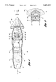
- FIG. 1 is a cross-sectional plan view of a sander employing the present invention
- FIG. 2a is a cross-sectional side elevation of the forward portion of the sander employing the present invention
- FIG. 2b is an exploded view of the sander shown in FIG. 2a with the head and elastic ring detached from the tool driveshaft;
- FIG. 3 is a cross-sectional plan view taken along section line 3--3 of FIG. 2b with the elastic ring not shown for illustration purposes.
- FIGS. 1-3 A sander 10 of the present invention is illustrated in FIGS. 1-3.
- Sander 10 is made up of an elongate body 12 formed by complementary right and left body portions 14 and 16. Right and left body portions are held together by a series of screws representatively illustrated by screws 18.
- Elongate body 12 defines an internal cavity 20 which extends along a central longitudinal axis 22.
- the drive motor is provided with a rotary output shaft 26 which is operatively connected to pivotally oscillating driveshaft 28.
- Driveshaft 28 is supported on the elongate body pivotally rotatable about pivot axis 30.
- pivot axis 30 is orthogonal to longitudinal axis 22.
- Driveshaft 22 is pivotally supported on body 12 by a pair of spaced apart bearings, namely, upper bushing 31 and roller bearing 32.
- Bushing 31 and roller bearing 32 are held in corresponding semi-cylindrical pockets formed in right and left housing portions 14 and 16.
- Roller bearing 32 is provided with an inner race which is affixed to the shaft and prevented from moving axially.
- Roller bearing 32 is preferably a conventional sealed roller ball bearing which thereby prevents dust and debris from entering into the body internal cavity 20.
- Pivot arm 34 is affixed to driveshaft 28 and extends rearwardly therefrom, as illustrated in FIGS. 1 and 2.
- the free end of pivot arm 34 is provided with a generally C-shaped opening.
- Motor 24 is provided with a rotary output shaft 26 connected to eccentric crank assembly 38.
- Eccentric crank assembly is pivotally supported on housing 12 by roller bearing 40.
- the eccentric crank assembly also includes a cooling fan 42 and an offset crank pin 44 supporting rolling ring 46. Rolling ring 46 is sized to fit within the C-shaped opening in the free end 36 of pivot arm 34. As motor 24 is driven, motor output shaft rotates the eccentric crank assembly.
- Crank pin 44 which is parallel to and radially offset from the longitudinal axis 22 drives roller ring in an orbital motion, causing the free end 36 of pivot arm 34 to oscillate back and forth, thereby pivotally rotationally oscillating driveshaft 28 through a small included angle.
- this angle is in the 1 to 7 degree range, and most preferably, in the 2 to 3 degree range.
- Driveshaft 28 is provided with a non-circular free end 48 which, in the preferred embodiment, is square in cross-section.
- Driveshaft free end 48 is adapted to removably receive a tool head assembly 50 which has a corresponding square opening 52 sized to cooperate with the driveshaft free end to drive the tool head assembly in a pivotally oscillating manner.
- Tool head assembly 50 has a mounting boss portion 54 which structurally forms square opening 52.
- Tool head assembly 50 also includes a forward head portion 56 which, in the embodiment illustrated, is generally triangular in shape and designed to receive the standard nine-sided sanding pads utilized in the Ryobi DS1000 sander.
- an elastic pad 60 Interposed between head 56 and sand paper sheet 58 is an elastic pad 60 which provides both a generally flat, soft planar surface for adhering the sand paper 58, but also spans the internal ribs molded into head 56.
- Head 56 is provided with an internal dust collection passageway 62 and extends from a series of intake ports adjacent the outer peripheral edge of head 56 to a region outboard of the driveshaft (illustrated in FIG. 3).
- Internal dust collection passageway 62 in head 56 is in fluid communication with an internal dust collection conduit 64 formed within body 12.
- the dust collection conduit 44 extends from a region immediately surrounding driveshaft 28 to an external dust collection port 66.
- Dust collection port 66 serves as a sight for the attachment of an external dust collection line to evacuate dust debris away from the sanding head 56 when in operation.
- the body 12 forms a pocket 68 which extends circumferentially about driveshaft free end 48.
- Pocket 68 is sized to receive elastic ring 70 which is interposed between body 12 and head assembly 50.
- Elastic ring 70 is loaded in compression axially, thereby biasing tool head assembly 50 away from body 12.
- Tool head assembly 50 is securely mounted to the free end of driveshaft 28 by socket-head cap screw 72, which extends through an axial hole in mounting boss 54 and cooperates with an axial threaded bore in driveshaft 28.
- cover 74 is affixed to a mounting boss 54 by screws 76 after the head assembly is secured to the driveshaft. Cover 74 sealingly cooperates with mounting boss 54 to define internal dust collection passageway 62 within head assembly 50.
- Mounting boss portion 54 of head assembly 50 is provided with a circumferential face 78 adapted to cooperate with elastic ring 70.
- face 78 is frustoconical in shape inwardly tapering at an angle which is approximately 45 degrees relative to pivot axis 30.
- elastic ring 70 is loaded radially, at least locally, thereby helping to reduce radial deflection of the driveshaft 28 relative to the housing when the tool is in use.
- pocket 68 while circular at its lowermost opening, is non-circular in the region of elastic ring 70.
- deformation is greatest in three locations. Those regions perpendicular to longitudinal axis 22 and a region aligned with the longitudinal axis 22 immediately rearward of pivot axis 30.
- Elastic ring 70 in the preferred embodiment, is circular in cross-section. However, it should be appreciated that other cross-sectional shapes such as square, oval or triangular rings, could be utilized as well.
- elastic ring 70 is formed of silicon rubber as opposed to conventional low cost O-ring material in order to reduce the likelihood of damage to the elastic ring resulting from heat generated from friction.
- elastic ring 70 has a free outer diameter of 1.125 inches (28.575 mm) and a free inside diameter of 0.859 inches (21.8186 mm), resulting in a cross-sectional diameter of 1.39 inches (35.306 mm).
- Elastic ring 70 preferably has a durometer of 65-75 on the Shore A scale, and most preferably, a durometer of 70 Shore A.
- the elastic ring 70 is compressed locally in the regions of maximum compression much greater than is typically done in a conventional O-ring installation. From the point at which elastic ring 70 is initially contacting both frustoconical face 78 and the uppermost surface of pocket 68, tool head assembly 50 is moved a distance with approximately 1/2 elastic ring diameter or approximately 0.070 inches (1.778 mm).
- the load exerted by the O-ring axially biases tool head assembly 50 and the attached driveshaft 28 away from tool body 12.
- This axial load takes up any slack which may exist in roller bearing 32, which has its inner race affixed to driveshaft 28 and its outermost race cooperating with the pocket formed in body 12 as illustrated in FIGS. 2a and 2b.
- the elastic ring 70 has proven to be very effective in stabilizing the vibration of the tool head assembly 50 relative to the body when the tool is in operation.
- noise and vibration in motor current draw increase and free motor speed decreases. It is believed that the vibration causes increased friction on roller bearing 32 and bushing 30, resulting in the decrease in motor speed.
Abstract
Description
Claims (11)
Priority Applications (3)
| Application Number | Priority Date | Filing Date | Title |
|---|---|---|---|
| US08/294,107 US5607343A (en) | 1994-08-22 | 1994-08-22 | Sander vibration isolator |
| PCT/US1995/009552 WO1996005939A1 (en) | 1994-08-22 | 1995-07-28 | Sander vibration isolator |
| AU32038/95A AU3203895A (en) | 1994-08-22 | 1995-07-28 | Sander vibration isolator |
Applications Claiming Priority (1)
| Application Number | Priority Date | Filing Date | Title |
|---|---|---|---|
| US08/294,107 US5607343A (en) | 1994-08-22 | 1994-08-22 | Sander vibration isolator |
Publications (1)
| Publication Number | Publication Date |
|---|---|
| US5607343A true US5607343A (en) | 1997-03-04 |
Family
ID=23131912
Family Applications (1)
| Application Number | Title | Priority Date | Filing Date |
|---|---|---|---|
| US08/294,107 Expired - Fee Related US5607343A (en) | 1994-08-22 | 1994-08-22 | Sander vibration isolator |
Country Status (3)
| Country | Link |
|---|---|
| US (1) | US5607343A (en) |
| AU (1) | AU3203895A (en) |
| WO (1) | WO1996005939A1 (en) |
Cited By (18)
| Publication number | Priority date | Publication date | Assignee | Title |
|---|---|---|---|---|
| US6199821B1 (en) * | 1996-02-12 | 2001-03-13 | Donald D. Job | Support and barrier ring |
| US6312322B1 (en) * | 2000-05-24 | 2001-11-06 | Po-Fu Chang | Hand held grinder |
| EP1358965A2 (en) * | 2002-04-30 | 2003-11-05 | C. & E. Fein Gmbh & Co. KG | Drive arrangement for oscillating spindle |
| US6758731B2 (en) | 2001-08-10 | 2004-07-06 | One World Technologies Limited | Orbital sander |
| US20050048884A1 (en) * | 2003-08-26 | 2005-03-03 | Credo Technology Corporation | Accessory attachment for rotary hand tools |
| US20050284646A1 (en) * | 2004-06-04 | 2005-12-29 | Dorin Bacila | Vibration reduction apparatus for power tool and power tool incorporating such apparatus |
| US7313838B2 (en) | 2002-12-03 | 2008-01-01 | S.C. Johnson & Son, Inc. | Powered cleaner/polisher |
| US20080006424A1 (en) * | 2006-07-06 | 2008-01-10 | Honsa Thomas W | Powered hand tool |
| US20080029134A1 (en) * | 2003-11-26 | 2008-02-07 | Long David C | Powered cleaner/polisher |
| US20080060827A1 (en) * | 2004-06-30 | 2008-03-13 | Torbjorn Gunnar Walheim | Power Tool With Dust Seal |
| US20090137194A1 (en) * | 2005-05-27 | 2009-05-28 | Kenji Fukuda | Polishing tool |
| US20100210194A1 (en) * | 2009-02-17 | 2010-08-19 | Walter Thomaschewski | Grinding Or Polishing Tool For An Oscillating Drive |
| WO2011000335A1 (en) * | 2009-07-03 | 2011-01-06 | 苏州宝时得电动工具有限公司 | Power tool |
| US20120305279A1 (en) * | 2010-01-07 | 2012-12-06 | Robert Bosch Gmbh | Hand Power Tool Device |
| US8517799B2 (en) | 2010-12-07 | 2013-08-27 | The Boeing Company | Robotic surface preparation by a random orbital device |
| CN104275686A (en) * | 2013-07-10 | 2015-01-14 | 苏州宝时得电动工具有限公司 | Swinging power tool |
| US9149923B2 (en) | 2010-11-09 | 2015-10-06 | Black & Decker Inc. | Oscillating tools and accessories |
| US10035237B2 (en) | 2011-11-02 | 2018-07-31 | The Boeing Company | Robotic end effector including multiple abrasion tools |
Families Citing this family (2)
| Publication number | Priority date | Publication date | Assignee | Title |
|---|---|---|---|---|
| DE19617573A1 (en) * | 1996-05-02 | 1997-11-06 | Bosch Gmbh Robert | Hand-held orbital sander |
| JP5852901B2 (en) * | 2012-02-24 | 2016-02-03 | 株式会社マキタ | Reciprocating rotary power tool |
Citations (24)
| Publication number | Priority date | Publication date | Assignee | Title |
|---|---|---|---|---|
| US2350098A (en) * | 1941-12-31 | 1944-05-30 | Black & Decker Mfg Co | Oscillating sander |
| US3831278A (en) * | 1972-08-03 | 1974-08-27 | Dynamics Corp America | Grass trimmer |
| US3886716A (en) * | 1973-02-26 | 1975-06-03 | Rockwell International Corp | Electrically powered grass trimmer |
| US3934344A (en) * | 1974-03-28 | 1976-01-27 | Kioritz Corporation | Portable chain saw |
| DE2742062A1 (en) * | 1976-09-27 | 1978-03-30 | Jean Robert | GRINDING MACHINE |
| US4136446A (en) * | 1977-01-24 | 1979-01-30 | Weed Eater, Inc. | Rotary cutting assembly with mechanical line feed |
| US4140446A (en) * | 1976-09-23 | 1979-02-20 | Atlas Copco Aktiebolag | Rotary pneumatic tool with vibration absorbing means |
| US4211004A (en) * | 1975-10-22 | 1980-07-08 | Emerson Electric Co. | String-type weed cutter with mechanical line feed |
| US4268233A (en) * | 1978-05-16 | 1981-05-19 | Atlas Copco Aktiebolag | Hand held rotary machine tool with vibration insulating means |
| US4391041A (en) * | 1981-04-20 | 1983-07-05 | The Toro Company | Powered ground care implement |
| US4635732A (en) * | 1983-09-28 | 1987-01-13 | Robert Bosch Gmbh | Power-driven hand-held tool with a pneumatic motor |
| US4759128A (en) * | 1986-02-13 | 1988-07-26 | Komatsu Zenoah Co. | Transmission device |
| US4817738A (en) * | 1986-08-27 | 1989-04-04 | Andreas Stihl | Portable handheld motor-driven tool |
| US4819742A (en) * | 1987-06-12 | 1989-04-11 | White Consolidated Industries, Inc. | Vibration-damping control handle for a portable power tool |
| US4825548A (en) * | 1987-03-31 | 1989-05-02 | White Consolidated Industries, Inc. | Vibration-damping control handle for a portable power tool |
| US4905420A (en) * | 1987-07-25 | 1990-03-06 | C. & E. Fein Gmbh & Co. | Grinder with dust exhaust means |
| US4905772A (en) * | 1988-09-01 | 1990-03-06 | Honsa Thomas W | Rotary power tool with vibration damping |
| US4920702A (en) * | 1985-11-15 | 1990-05-01 | C. & E. Fein Gmbh & Co. | Portable grinder |
| DE3840974A1 (en) * | 1988-12-06 | 1990-06-07 | Fein C & E | OSCILLATION DRIVE |
| US5123216A (en) * | 1985-11-15 | 1992-06-23 | C. & E. Fein Gmbh & Co. | Portable grinder |
| WO1993007589A1 (en) * | 1991-09-28 | 1993-04-15 | Anritsu Corporation | Device for sorting coins |
| WO1993025346A1 (en) * | 1992-06-15 | 1993-12-23 | Uniroc Grinding Ab | Vibration dampening grinding cup and grinding cup holder for handheld grinding machines |
| US5319889A (en) * | 1991-08-03 | 1994-06-14 | C. & E. Fein Gmbh & Co. | Grinder with dust exhaust means |
| US5375666A (en) * | 1993-07-23 | 1994-12-27 | Ryobi Outdoor Products | Vibration isolator for a portable power tool |
-
1994
- 1994-08-22 US US08/294,107 patent/US5607343A/en not_active Expired - Fee Related
-
1995
- 1995-07-28 AU AU32038/95A patent/AU3203895A/en not_active Abandoned
- 1995-07-28 WO PCT/US1995/009552 patent/WO1996005939A1/en active Application Filing
Patent Citations (24)
| Publication number | Priority date | Publication date | Assignee | Title |
|---|---|---|---|---|
| US2350098A (en) * | 1941-12-31 | 1944-05-30 | Black & Decker Mfg Co | Oscillating sander |
| US3831278A (en) * | 1972-08-03 | 1974-08-27 | Dynamics Corp America | Grass trimmer |
| US3886716A (en) * | 1973-02-26 | 1975-06-03 | Rockwell International Corp | Electrically powered grass trimmer |
| US3934344A (en) * | 1974-03-28 | 1976-01-27 | Kioritz Corporation | Portable chain saw |
| US4211004A (en) * | 1975-10-22 | 1980-07-08 | Emerson Electric Co. | String-type weed cutter with mechanical line feed |
| US4140446A (en) * | 1976-09-23 | 1979-02-20 | Atlas Copco Aktiebolag | Rotary pneumatic tool with vibration absorbing means |
| DE2742062A1 (en) * | 1976-09-27 | 1978-03-30 | Jean Robert | GRINDING MACHINE |
| US4136446A (en) * | 1977-01-24 | 1979-01-30 | Weed Eater, Inc. | Rotary cutting assembly with mechanical line feed |
| US4268233A (en) * | 1978-05-16 | 1981-05-19 | Atlas Copco Aktiebolag | Hand held rotary machine tool with vibration insulating means |
| US4391041A (en) * | 1981-04-20 | 1983-07-05 | The Toro Company | Powered ground care implement |
| US4635732A (en) * | 1983-09-28 | 1987-01-13 | Robert Bosch Gmbh | Power-driven hand-held tool with a pneumatic motor |
| US4920702A (en) * | 1985-11-15 | 1990-05-01 | C. & E. Fein Gmbh & Co. | Portable grinder |
| US5123216A (en) * | 1985-11-15 | 1992-06-23 | C. & E. Fein Gmbh & Co. | Portable grinder |
| US4759128A (en) * | 1986-02-13 | 1988-07-26 | Komatsu Zenoah Co. | Transmission device |
| US4817738A (en) * | 1986-08-27 | 1989-04-04 | Andreas Stihl | Portable handheld motor-driven tool |
| US4825548A (en) * | 1987-03-31 | 1989-05-02 | White Consolidated Industries, Inc. | Vibration-damping control handle for a portable power tool |
| US4819742A (en) * | 1987-06-12 | 1989-04-11 | White Consolidated Industries, Inc. | Vibration-damping control handle for a portable power tool |
| US4905420A (en) * | 1987-07-25 | 1990-03-06 | C. & E. Fein Gmbh & Co. | Grinder with dust exhaust means |
| US4905772A (en) * | 1988-09-01 | 1990-03-06 | Honsa Thomas W | Rotary power tool with vibration damping |
| DE3840974A1 (en) * | 1988-12-06 | 1990-06-07 | Fein C & E | OSCILLATION DRIVE |
| US5319889A (en) * | 1991-08-03 | 1994-06-14 | C. & E. Fein Gmbh & Co. | Grinder with dust exhaust means |
| WO1993007589A1 (en) * | 1991-09-28 | 1993-04-15 | Anritsu Corporation | Device for sorting coins |
| WO1993025346A1 (en) * | 1992-06-15 | 1993-12-23 | Uniroc Grinding Ab | Vibration dampening grinding cup and grinding cup holder for handheld grinding machines |
| US5375666A (en) * | 1993-07-23 | 1994-12-27 | Ryobi Outdoor Products | Vibration isolator for a portable power tool |
Cited By (28)
| Publication number | Priority date | Publication date | Assignee | Title |
|---|---|---|---|---|
| US6199821B1 (en) * | 1996-02-12 | 2001-03-13 | Donald D. Job | Support and barrier ring |
| US6312322B1 (en) * | 2000-05-24 | 2001-11-06 | Po-Fu Chang | Hand held grinder |
| US20050003748A1 (en) * | 2001-08-10 | 2005-01-06 | One World Technologies, Limited | Orbital sander |
| US7270598B2 (en) | 2001-08-10 | 2007-09-18 | Eastway Fair Company Ltd. | Orbital sander |
| US6758731B2 (en) | 2001-08-10 | 2004-07-06 | One World Technologies Limited | Orbital sander |
| EP1358965A3 (en) * | 2002-04-30 | 2004-04-07 | C. & E. FEIN GmbH | Drive arrangement for oscillating spindle |
| EP1358965A2 (en) * | 2002-04-30 | 2003-11-05 | C. & E. Fein Gmbh & Co. KG | Drive arrangement for oscillating spindle |
| US7313838B2 (en) | 2002-12-03 | 2008-01-01 | S.C. Johnson & Son, Inc. | Powered cleaner/polisher |
| US20050048884A1 (en) * | 2003-08-26 | 2005-03-03 | Credo Technology Corporation | Accessory attachment for rotary hand tools |
| US7052382B2 (en) * | 2003-08-26 | 2006-05-30 | Credo Technology Corporation | Accessory attachment for rotary hand tools |
| US7565712B2 (en) | 2003-11-26 | 2009-07-28 | S.C. Johnson & Son, Inc. | Powered cleaner/polisher |
| US20080029134A1 (en) * | 2003-11-26 | 2008-02-07 | Long David C | Powered cleaner/polisher |
| US20050284646A1 (en) * | 2004-06-04 | 2005-12-29 | Dorin Bacila | Vibration reduction apparatus for power tool and power tool incorporating such apparatus |
| US7322428B2 (en) | 2004-06-04 | 2008-01-29 | Black & Decker Inc. | Vibration reduction apparatus for power tool and power tool incorporating such apparatus |
| US20080060827A1 (en) * | 2004-06-30 | 2008-03-13 | Torbjorn Gunnar Walheim | Power Tool With Dust Seal |
| US20090137194A1 (en) * | 2005-05-27 | 2009-05-28 | Kenji Fukuda | Polishing tool |
| US7717772B2 (en) * | 2005-05-27 | 2010-05-18 | Nitto Kohki Co., Ltd. | Polishing tool |
| US20080006424A1 (en) * | 2006-07-06 | 2008-01-10 | Honsa Thomas W | Powered hand tool |
| US7610968B1 (en) * | 2006-07-06 | 2009-11-03 | Honsa Ergonomic Technologies, Inc. | Powered hand tool |
| US7401662B2 (en) * | 2006-07-06 | 2008-07-22 | Honsa Ergonomic Technologies, Inc. | Powered hand tool |
| US9421663B2 (en) | 2009-02-17 | 2016-08-23 | C. & E. Fein Gmbh | Grinding or polishing tool for an oscillating drive |
| US20100210194A1 (en) * | 2009-02-17 | 2010-08-19 | Walter Thomaschewski | Grinding Or Polishing Tool For An Oscillating Drive |
| WO2011000335A1 (en) * | 2009-07-03 | 2011-01-06 | 苏州宝时得电动工具有限公司 | Power tool |
| US20120305279A1 (en) * | 2010-01-07 | 2012-12-06 | Robert Bosch Gmbh | Hand Power Tool Device |
| US9149923B2 (en) | 2010-11-09 | 2015-10-06 | Black & Decker Inc. | Oscillating tools and accessories |
| US8517799B2 (en) | 2010-12-07 | 2013-08-27 | The Boeing Company | Robotic surface preparation by a random orbital device |
| US10035237B2 (en) | 2011-11-02 | 2018-07-31 | The Boeing Company | Robotic end effector including multiple abrasion tools |
| CN104275686A (en) * | 2013-07-10 | 2015-01-14 | 苏州宝时得电动工具有限公司 | Swinging power tool |
Also Published As
| Publication number | Publication date |
|---|---|
| WO1996005939A1 (en) | 1996-02-29 |
| AU3203895A (en) | 1996-03-14 |
Similar Documents
| Publication | Publication Date | Title |
|---|---|---|
| US5607343A (en) | Sander vibration isolator | |
| US6729937B2 (en) | Barrel-polishing apparatus | |
| US7104873B1 (en) | Anti-vibration arrangement | |
| KR101237040B1 (en) | Device for guiding a shaft in an oscillating movement | |
| CN1112982C (en) | Electric hand tool machine | |
| US5437571A (en) | Detail sander | |
| US4242839A (en) | High-speed power tool | |
| JP2984318B2 (en) | Portable work machine guided by hand | |
| US20040016133A1 (en) | Adjustable antivibration system, in particular for a hand-held work machine | |
| EP0925880A3 (en) | Suspension mechanism for a combustion chamber fan motor of a combustion powered tool | |
| JPH11333692A (en) | Hand-held power tool | |
| US5561909A (en) | Battery operated saw | |
| GB2260721A (en) | Sanding tool with dust collector | |
| US5888128A (en) | Hand grinder | |
| SE510893C2 (en) | Hand apparatus for operating a sideways machining tool | |
| CA2255501C (en) | Barrel-polishing apparatus | |
| EP1277543A3 (en) | Oscillating hand tool | |
| SE9300594D0 (en) | DEVICE FOR DEVIBRATION OF ROTATION GRINDING MACHINE WITH SELF-CENTERING GRINDING DISC | |
| GB2359266A (en) | Eccentric disc sander | |
| JP3213060B2 (en) | Reciprocating machine | |
| EP1447173A1 (en) | Connecting foot for orbital movement machines for machining surfaces, in particular orbital sanders, and orbital sanding machine using the said foot | |
| JP3508261B2 (en) | Vibration tool | |
| CN215058379U (en) | Oscillating mechanism of air supply device and tower fan | |
| KR920003606Y1 (en) | Drill machine | |
| KR20010049189A (en) | Drive wheel |
Legal Events
| Date | Code | Title | Description |
|---|---|---|---|
| AS | Assignment |
Owner name: RYOBI MOTOR PRODUCTS CORP., SOUTH CAROLINA Free format text: ASSIGNMENT OF ASSIGNORS INTEREST;ASSIGNORS:KEITH, JAMES R., JR.;BALLEW, WILLIAM STANLEY;REEL/FRAME:007231/0285 Effective date: 19941018 |
|
| AS | Assignment |
Owner name: HSBC BANK USA, NEW YORK Free format text: SECURITY INTEREST;ASSIGNORS:ONE WORLD TECHNOLOGIES INC.;RYOBI TECHNOLOGIES, INC.;OWT INDUSTRIES, INC.;REEL/FRAME:011103/0770 Effective date: 20000801 |
|
| AS | Assignment |
Owner name: ONE WORLD TECHNOLOGIES, INC., SOUTH CAROLINA Free format text: ASSIGNMENT OF ASSIGNORS INTEREST;ASSIGNOR:RYOBI NORTH AMERICA, INC.;REEL/FRAME:011149/0407 Effective date: 20000731 |
|
| REMI | Maintenance fee reminder mailed | ||
| LAPS | Lapse for failure to pay maintenance fees | ||
| FP | Lapsed due to failure to pay maintenance fee |
Effective date: 20010304 |
|
| AS | Assignment |
Owner name: ONE WORLD TECHNOLOGIES LIMITED, BERMUDA Free format text: ASSIGNMENT OF ASSIGNORS INTEREST;ASSIGNOR:ONE WORLD TECHNOLOGIES, INC.;REEL/FRAME:014066/0731 Effective date: 20030512 |
|
| STCH | Information on status: patent discontinuation |
Free format text: PATENT EXPIRED DUE TO NONPAYMENT OF MAINTENANCE FEES UNDER 37 CFR 1.362 |