EP1600138A2 - Ablauf - Google Patents
Ablauf Download PDFInfo
- Publication number
- EP1600138A2 EP1600138A2 EP05103233A EP05103233A EP1600138A2 EP 1600138 A2 EP1600138 A2 EP 1600138A2 EP 05103233 A EP05103233 A EP 05103233A EP 05103233 A EP05103233 A EP 05103233A EP 1600138 A2 EP1600138 A2 EP 1600138A2
- Authority
- EP
- European Patent Office
- Prior art keywords
- valve cone
- vacuum chamber
- drain
- cover
- inlet
- Prior art date
- Legal status (The legal status is an assumption and is not a legal conclusion. Google has not performed a legal analysis and makes no representation as to the accuracy of the status listed.)
- Granted
Links
Images


Classifications
-
- E—FIXED CONSTRUCTIONS
- E03—WATER SUPPLY; SEWERAGE
- E03C—DOMESTIC PLUMBING INSTALLATIONS FOR FRESH WATER OR WASTE WATER; SINKS
- E03C1/00—Domestic plumbing installations for fresh water or waste water; Sinks
- E03C1/12—Plumbing installations for waste water; Basins or fountains connected thereto; Sinks
- E03C1/22—Outlet devices mounted in basins, baths, or sinks
- E03C1/23—Outlet devices mounted in basins, baths, or sinks with mechanical closure mechanisms
- E03C1/2302—Outlet devices mounted in basins, baths, or sinks with mechanical closure mechanisms the actuation force being transmitted to the plug via rigid elements
-
- E—FIXED CONSTRUCTIONS
- E03—WATER SUPPLY; SEWERAGE
- E03C—DOMESTIC PLUMBING INSTALLATIONS FOR FRESH WATER OR WASTE WATER; SINKS
- E03C1/00—Domestic plumbing installations for fresh water or waste water; Sinks
- E03C1/12—Plumbing installations for waste water; Basins or fountains connected thereto; Sinks
- E03C1/22—Outlet devices mounted in basins, baths, or sinks
- E03C1/23—Outlet devices mounted in basins, baths, or sinks with mechanical closure mechanisms
-
- A—HUMAN NECESSITIES
- A61—MEDICAL OR VETERINARY SCIENCE; HYGIENE
- A61H—PHYSICAL THERAPY APPARATUS, e.g. DEVICES FOR LOCATING OR STIMULATING REFLEX POINTS IN THE BODY; ARTIFICIAL RESPIRATION; MASSAGE; BATHING DEVICES FOR SPECIAL THERAPEUTIC OR HYGIENIC PURPOSES OR SPECIFIC PARTS OF THE BODY
- A61H33/00—Bathing devices for special therapeutic or hygienic purposes
- A61H2033/0008—Arrangement for cleaning the installation before or after use
- A61H2033/0033—Arrangement for cleaning the installation before or after use by draining-off pumps, nozzles, waterlines by gravity
Definitions
- the poppet is movable independently of the cover, so that the cover is rigidly mounted to the bottom of the tub and no adjustment with the valve plug is necessary.
- an actuating mechanism provided by means of the valve cone by train and pressure in opposite directions Directions is movable. This allows the inlet seen from the tub be arranged completely independent of the actuating mechanism and the Poppet can be moved in both directions to open the drain and close.
- the load on train is required to be at a negative pressure in the vacuum chamber to avoid lifting the valve cone. Will the Valve cone pushed up, the access to the drain body can be opened.
- the process thus formed is easy to assemble, in particular, is no adjustment the valve cone to the cover more required.
- the drain For easy installation of the drain are arranged annularly at the inlet Ribs arranged to form a Haarfangsiebes. These ribs are after Remove the cover from above freely accessible, so that gets dirty easy to remove from the ribs.
- the cover is preferred for this purpose lockable with the enema.
- the drain has an inlet 2, which is arranged within the tub Cover 3 has, via ribs 4 of the flange of the inlet. 2 is spaced.
- the ribs 4 form a hair trap, so that in a circulation of water do not clog the pipes.
- the inlet 2 has a nozzle 5, which passes through the trough 1 and has a thread 6 at one end portion, on which an internal thread of a housing 7 of the drain is screwed.
- a seal 8 is provided, which from below against the trough. 1 pushes, so that the process is fixed to the tub 1 by clamping.
- the inlet 2 is held stationary with the cover 3 and has no moving parts.
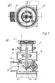
- FIGS. 2A and 2B show the closed position of the valve cone 11. in a water circulation between a located in the tub 1 Fluid and the suction line 10 can take place.
- the valve cone 11 has this a disc-shaped portion 16, on whose annular groove a seal 17 is inserted, with a sealing lip on a wall 25 of a channel between Vacuum chamber 9 and drain body 12 is arranged.
- the valve cone 18 also has an upwardly into the vacuum chamber 9 protruding Handle portion 18 and a downwardly extending shaft 19, which with an actuating mechanism in connection.
- the actuating mechanism comprises a pivotable lever 20 which is a Axis 21 is rotatable and has a slot having a portion 22 with lesser Width and has a region 24 with greater width.
- a pivotable lever 20 which is a Axis 21 is rotatable and has a slot having a portion 22 with lesser Width and has a region 24 with greater width.
- an end portion 23 of the valve cone 11 with a led mushroom-like projection In the two areas 22 and 24 of the elongated hole is an end portion 23 of the valve cone 11 with a led mushroom-like projection.
- the poppet 11 In the position shown in Figure 2A, the poppet 11 is fixed in the closed position, wherein also a higher negative pressure in the vacuum chamber 9, the valve cone 11 does not lift, as this by the lever 20 in the closed position is held and a certain tensile force and the valve plug 11 in the lower Holding position. At too high a negative pressure, the sealing lip 17 of the Wall 25 are lifted off, thus allowing an influx of air from the Drain body 12, the pressure difference for safety reasons not too high to be let.
- FIGS. 3A and 3B the raised position of the valve cone 11 is shown. in which the fluid is emptied through the drain body 12.
- the lever is 20 has been pivoted and the poppet 11 was above the shaft 19 upwards pressed so that the fluid from the vacuum chamber 9 to empty down can.
- a distance between the poppet 11 and the cover 3 present is also in the raised position.
- the actuating mechanism 20 are moved to the raised position, so that the end portion 23 of the Poppet 11 is inserted only in the slot 23, 24 and engages. Subsequently the drain is fully functional without any adjustment of the cover in view of the movement of the valve cone 11 is required.
Landscapes
- Engineering & Computer Science (AREA)
- Mechanical Engineering (AREA)
- Environmental & Geological Engineering (AREA)
- Health & Medical Sciences (AREA)
- Life Sciences & Earth Sciences (AREA)
- Hydrology & Water Resources (AREA)
- Public Health (AREA)
- Water Supply & Treatment (AREA)
- Self-Closing Valves And Venting Or Aerating Valves (AREA)
- Control And Other Processes For Unpacking Of Materials (AREA)
- Jet Pumps And Other Pumps (AREA)
- Sink And Installation For Waste Water (AREA)
- Iron Core Of Rotating Electric Machines (AREA)
- Valve Device For Special Equipments (AREA)
- Sorption Type Refrigeration Machines (AREA)
- Sanitary Device For Flush Toilet (AREA)
Abstract
Description
- Figur 1
- eine perspektivische Ansicht eines Ausführungsbeispieles eines erfindungsgemäßen Ablaufes;
- Figur 2A und 2B
- zwei Ansichten des Ablaufes der Figur 1 mit geschlossenem Ventilkegel;
- Figur 3A und 3B
- zwei Ansichten des Ablaufes der Figur 1 mit geöffentem Ventilkegel, und
- Figur 4A und 4B
- zwei Ansichten des Ablaufes der Figur 1 bei der Demontage des Ventilkegels.
Claims (9)
- Ablauf, insbesondere für einen Whirlpool, mit einem an einer Wanne (1) montierbaren Einlauf (2) mit einer Abdeckung (3), der über eine Unterdruckkammer (9) mit einer Ansaugleitung (10) in Verbindung steht, und einem unter der Unterdruckkammer (9) angeordneten Ablauf (12), wobei Unterdruckkammer (9) und Ablauf (2) durch einen mit einem Ventilkegel (11) trennbaren Kanal verbunden sind, dadurch gekennzeichnet, dass der Ventilkegel (11) unabhängig von der Abdeckung (3) bewegbar ist und eine Betätigungsmechanik (20) vorgesehen ist, mittels der der Ventilkegel (11) durch Zug und Druck in gegenläufige Richtungen bewegbar ist.
- Ablauf nach Anspruch 1, dadurch gekennzeichnet, dass der Ventilkegel (11) beabstandet von der Abdeckung (3) des Einlaufs (2) angeordnet ist.
- Ablauf nach Anspruch 1 oder 2, dadurch gekennzeichnet, dass der Ventilkegel (11) einen scheibenförmigen Abschnitt (16) mit einer ringförmigen Dichtung (17) aufweist, die an eine Wand (25) des Kanals zwischen Unterdruckkammer (9) und Ablauf (12) anlegbar ist.
- Ablauf nach einem der Ansprüche 1 bis 3, dadurch gekennzeichnet, dass der Ventilkegel (11) für die Demontage einen in die Unterdruckkammer (9) hervorstehenden Griffabschnitt (18) aufweist.
- Ablauf nach einem der Ansprüche 1 bis 4, dadurch gekennzeichnet, dass der Ventilkegel (11) in einer angehobenen Position von der Betätigungsmechanik (20) lösbar ist.
- Ablauf nach einem der Ansprüche 1 bis 5, dadurch gekennzeichnet, dass die Betätigungsmechanik einen Hebel (20) aufweist, der über eine Rastverbindung (22, 23, 24) mit dem Ventilkegel (11) verbunden ist.
- Ablauf nach Anspruch 6, dadurch gekennzeichnet, dass an dem Hebel (20) ein Langloch (22, 24) ausgebildet ist, an dem ein unterer Abschnitt (23) des Ventilkegels (11) mit einem pilzkopfartigen Vorsprung geführt ist.
- Ablauf nach einem der Ansprüche 1 bis 7, dadurch gekennzeichnet, dass an dem Einlauf (2) ringförmig angeordnete Rippen (4) zur Bildung eines Haarfangsiebes angeordnet sind.
- Ablauf nach einem der Ansprüche 1 bis 8, dadurch gekennzeichnet, dass der Einlauf (2) einen an der Wanne (1) montierbaren Stutzen (5) und eine beabstandet von dem Stutzen (5) aufsteckbare Abdeckung (3) aufweist.
Applications Claiming Priority (2)
| Application Number | Priority Date | Filing Date | Title |
|---|---|---|---|
| DE202004008315U DE202004008315U1 (de) | 2004-05-25 | 2004-05-25 | Ablauf |
| DE202004008315U | 2004-05-25 |
Publications (3)
| Publication Number | Publication Date |
|---|---|
| EP1600138A2 true EP1600138A2 (de) | 2005-11-30 |
| EP1600138A3 EP1600138A3 (de) | 2005-12-21 |
| EP1600138B1 EP1600138B1 (de) | 2008-11-05 |
Family
ID=34981200
Family Applications (1)
| Application Number | Title | Priority Date | Filing Date |
|---|---|---|---|
| EP05103233A Expired - Lifetime EP1600138B1 (de) | 2004-05-25 | 2005-04-21 | Ablauf |
Country Status (6)
| Country | Link |
|---|---|
| EP (1) | EP1600138B1 (de) |
| AT (1) | ATE413495T1 (de) |
| DE (2) | DE202004008315U1 (de) |
| DK (1) | DK1600138T3 (de) |
| ES (1) | ES2315794T3 (de) |
| PT (1) | PT1600138E (de) |
Cited By (3)
| Publication number | Priority date | Publication date | Assignee | Title |
|---|---|---|---|---|
| DE102011000676A1 (de) | 2011-02-11 | 2012-08-16 | Franz Kaldewei Gmbh & Co. Kg | Sanitärwanne |
| CN107653942A (zh) * | 2017-09-29 | 2018-02-02 | 浙江德利福科技股份有限公司 | 去水器 |
| EP3444407A1 (de) * | 2017-08-14 | 2019-02-20 | Zhejiang Delifu Technology Co., Ltd | Ablauf mit verschluss |
Families Citing this family (5)
| Publication number | Priority date | Publication date | Assignee | Title |
|---|---|---|---|---|
| DE102006007177A1 (de) | 2006-02-03 | 2007-08-09 | Hansgrohe Ag | Ablaufgarnitur für Whirlpools |
| NL1032083C2 (nl) * | 2006-06-29 | 2008-01-02 | Easy Sanitairy Solutions Bv | Platte afvoer. |
| FR2924135B1 (fr) * | 2007-11-28 | 2012-08-17 | Victor Jean Ballestra | Dispositif de vidage pour appareil sanitaire equipe de moyens d'hydrotherapie |
| PL2390428T3 (pl) * | 2009-01-20 | 2020-04-30 | Ningbo Bosheng Plumbing Co., Ltd | Urządzenie odwadniające do urządzeń kuchennych i łazienkowych |
| DE202011106651U1 (de) * | 2011-10-12 | 2013-01-16 | Viega Gmbh & Co. Kg | Ablaufgarnitur mit Wechselventil für Whirlpool-Wannen |
Family Cites Families (10)
| Publication number | Priority date | Publication date | Assignee | Title |
|---|---|---|---|---|
| US3571820A (en) * | 1968-06-06 | 1971-03-23 | Jacuzzi Research Inc | Hydromassage bath installation |
| AT375988B (de) * | 1983-05-11 | 1984-09-25 | Oespag Oesterr Sanitaer | Kombiniertes ueberlauf- und abflussventil |
| DE3636328C2 (de) * | 1986-10-24 | 1994-07-07 | Moeller Sanitaer Und Kunststof | Vorrichtung zum Einbau in das Abflußsystem von Badewannen |
| IT1231901B (it) * | 1987-10-19 | 1992-01-15 | Jacuzzi Europ | Complesso per disinfezione del circuito idraulico di un impianto di idromassaggio |
| DE3928464C2 (de) * | 1989-08-29 | 1995-11-23 | Roth Werke Gmbh | Whirlpool-Wanne |
| DE4038501A1 (de) * | 1990-12-03 | 1992-06-04 | Schuessler Guenter | Absaug-und einstrahlvorrichtung fuer ein wasserbecken |
| NO301031B1 (no) * | 1991-04-09 | 1997-09-01 | Vico Products Mfg Co As | Dreneringsventil |
| DE29823021U1 (de) * | 1998-12-24 | 1999-02-18 | Franz Viegener II GmbH & Co. KG, 57439 Attendorn | Ablaufgarnitur für eine Badewanne |
| DE10038246B4 (de) * | 1999-08-10 | 2005-12-15 | Desch, Kurt Michael, Dipl.-Ing. (FH) | Badewannen Überlaufgarnitur mit horizontalem Wannenüberlauf |
| DE20212292U1 (de) * | 2002-08-09 | 2003-12-18 | Franz Viegener Ii Gmbh & Co. Kg | Ablaufgarnitur |
-
2004
- 2004-05-25 DE DE202004008315U patent/DE202004008315U1/de not_active Expired - Lifetime
-
2005
- 2005-04-21 ES ES05103233T patent/ES2315794T3/es not_active Expired - Lifetime
- 2005-04-21 EP EP05103233A patent/EP1600138B1/de not_active Expired - Lifetime
- 2005-04-21 DK DK05103233T patent/DK1600138T3/da active
- 2005-04-21 AT AT05103233T patent/ATE413495T1/de active
- 2005-04-21 PT PT05103233T patent/PT1600138E/pt unknown
- 2005-04-21 DE DE502005005852T patent/DE502005005852D1/de not_active Expired - Fee Related
Cited By (3)
| Publication number | Priority date | Publication date | Assignee | Title |
|---|---|---|---|---|
| DE102011000676A1 (de) | 2011-02-11 | 2012-08-16 | Franz Kaldewei Gmbh & Co. Kg | Sanitärwanne |
| EP3444407A1 (de) * | 2017-08-14 | 2019-02-20 | Zhejiang Delifu Technology Co., Ltd | Ablauf mit verschluss |
| CN107653942A (zh) * | 2017-09-29 | 2018-02-02 | 浙江德利福科技股份有限公司 | 去水器 |
Also Published As
| Publication number | Publication date |
|---|---|
| ES2315794T3 (es) | 2009-04-01 |
| DE202004008315U1 (de) | 2005-10-06 |
| DE502005005852D1 (de) | 2008-12-18 |
| ATE413495T1 (de) | 2008-11-15 |
| EP1600138B1 (de) | 2008-11-05 |
| EP1600138A3 (de) | 2005-12-21 |
| DK1600138T3 (da) | 2009-02-23 |
| PT1600138E (pt) | 2009-01-09 |
Similar Documents
| Publication | Publication Date | Title |
|---|---|---|
| DE2837967C2 (de) | Wasserablaufbehälter | |
| DE112010003584T5 (de) | Notfall-waschsystem | |
| DE102011000676A1 (de) | Sanitärwanne | |
| EP1600138B1 (de) | Ablauf | |
| DE102009023015B4 (de) | Ablauf, insbesondere für sanitäre Einrichtungen | |
| DE19704430A1 (de) | Geschirrspülmaschine | |
| EP2258905B1 (de) | Ablauf, insbesondere für sanitäre Einrichtungen | |
| DE202005010233U1 (de) | Hebelbetätigte, automatische Absperranordnung | |
| EP3502364A2 (de) | Rohrbelüfter und system zur rohrbelüftung | |
| DE202005004307U1 (de) | Inseldunstabzugshaube | |
| EP1447486A2 (de) | Ablauf | |
| DE19910254C2 (de) | Hebeanlage für Abwasser | |
| EP3272954B1 (de) | Ablaufanordnung | |
| DE102008049007B4 (de) | Flüssigkeitsfilter | |
| DE202021106962U1 (de) | Wasserablassventil mit einstellbarer Auslassgeschwindigkeit | |
| EP1388617B1 (de) | Ablaufgarnitur | |
| DE9112021U1 (de) | Wasserauslaufarmatur | |
| EP1600685B1 (de) | Kombination aus einem Heizapparat und einem Verschluss für eine Kondensatabfuhr | |
| EP1978910A1 (de) | Ablaufgarnitur für whirlpools | |
| EP1013837A2 (de) | Ablaufgarnitur für eine Badewanne | |
| EP2787133A1 (de) | Sanitäreinrichtungen | |
| DE2145726A1 (de) | Klosettschussel | |
| EP3775416B1 (de) | Siphon | |
| DE19706795C1 (de) | Spüle | |
| EP3647504B1 (de) | Sanitärartikelanordnung |
Legal Events
| Date | Code | Title | Description |
|---|---|---|---|
| PUAI | Public reference made under article 153(3) epc to a published international application that has entered the european phase |
Free format text: ORIGINAL CODE: 0009012 |
|
| PUAL | Search report despatched |
Free format text: ORIGINAL CODE: 0009013 |
|
| AK | Designated contracting states |
Kind code of ref document: A2 Designated state(s): AT BE BG CH CY CZ DE DK EE ES FI FR GB GR HU IE IS IT LI LT LU MC NL PL PT RO SE SI SK TR |
|
| AX | Request for extension of the european patent |
Extension state: AL BA HR LV MK YU |
|
| AK | Designated contracting states |
Kind code of ref document: A3 Designated state(s): AT BE BG CH CY CZ DE DK EE ES FI FR GB GR HU IE IS IT LI LT LU MC NL PL PT RO SE SI SK TR |
|
| AX | Request for extension of the european patent |
Extension state: AL BA HR LV MK YU |
|
| RIC1 | Information provided on ipc code assigned before grant |
Ipc: 7A 61H 33/00 B Ipc: 7E 03C 1/23 A |
|
| 17P | Request for examination filed |
Effective date: 20060421 |
|
| AKX | Designation fees paid |
Designated state(s): AT BE BG CH CY CZ DE DK EE ES FI FR GB GR HU IE IS IT LI LT LU MC NL PL PT RO SE SI SK TR |
|
| 17Q | First examination report despatched |
Effective date: 20061004 |
|
| GRAP | Despatch of communication of intention to grant a patent |
Free format text: ORIGINAL CODE: EPIDOSNIGR1 |
|
| GRAS | Grant fee paid |
Free format text: ORIGINAL CODE: EPIDOSNIGR3 |
|
| GRAA | (expected) grant |
Free format text: ORIGINAL CODE: 0009210 |
|
| AK | Designated contracting states |
Kind code of ref document: B1 Designated state(s): AT BE BG CH CY CZ DE DK EE ES FI FR GB GR HU IE IS IT LI LT LU MC NL PL PT RO SE SI SK TR |
|
| REG | Reference to a national code |
Ref country code: GB Ref legal event code: FG4D Free format text: NOT ENGLISH |
|
| REG | Reference to a national code |
Ref country code: CH Ref legal event code: EP |
|
| REG | Reference to a national code |
Ref country code: CH Ref legal event code: NV Representative=s name: TROESCH SCHEIDEGGER WERNER AG |
|
| REG | Reference to a national code |
Ref country code: IE Ref legal event code: FG4D Free format text: LANGUAGE OF EP DOCUMENT: GERMAN |
|
| REF | Corresponds to: |
Ref document number: 502005005852 Country of ref document: DE Date of ref document: 20081218 Kind code of ref document: P |
|
| REG | Reference to a national code |
Ref country code: PT Ref legal event code: SC4A Free format text: AVAILABILITY OF NATIONAL TRANSLATION Effective date: 20081229 |
|
| REG | Reference to a national code |
Ref country code: SE Ref legal event code: TRGR |
|
| REG | Reference to a national code |
Ref country code: DK Ref legal event code: T3 |
|
| NLV1 | Nl: lapsed or annulled due to failure to fulfill the requirements of art. 29p and 29m of the patents act | ||
| REG | Reference to a national code |
Ref country code: ES Ref legal event code: FG2A Ref document number: 2315794 Country of ref document: ES Kind code of ref document: T3 |
|
| LTIE | Lt: invalidation of european patent or patent extension |
Effective date: 20081105 |
|
| PG25 | Lapsed in a contracting state [announced via postgrant information from national office to epo] |
Ref country code: LT Free format text: LAPSE BECAUSE OF FAILURE TO SUBMIT A TRANSLATION OF THE DESCRIPTION OR TO PAY THE FEE WITHIN THE PRESCRIBED TIME-LIMIT Effective date: 20081105 |
|
| PG25 | Lapsed in a contracting state [announced via postgrant information from national office to epo] |
Ref country code: SI Free format text: LAPSE BECAUSE OF FAILURE TO SUBMIT A TRANSLATION OF THE DESCRIPTION OR TO PAY THE FEE WITHIN THE PRESCRIBED TIME-LIMIT Effective date: 20081105 Ref country code: NL Free format text: LAPSE BECAUSE OF FAILURE TO SUBMIT A TRANSLATION OF THE DESCRIPTION OR TO PAY THE FEE WITHIN THE PRESCRIBED TIME-LIMIT Effective date: 20081105 Ref country code: IS Free format text: LAPSE BECAUSE OF FAILURE TO SUBMIT A TRANSLATION OF THE DESCRIPTION OR TO PAY THE FEE WITHIN THE PRESCRIBED TIME-LIMIT Effective date: 20090305 Ref country code: PL Free format text: LAPSE BECAUSE OF FAILURE TO SUBMIT A TRANSLATION OF THE DESCRIPTION OR TO PAY THE FEE WITHIN THE PRESCRIBED TIME-LIMIT Effective date: 20081105 Ref country code: FI Free format text: LAPSE BECAUSE OF FAILURE TO SUBMIT A TRANSLATION OF THE DESCRIPTION OR TO PAY THE FEE WITHIN THE PRESCRIBED TIME-LIMIT Effective date: 20081105 |
|
| REG | Reference to a national code |
Ref country code: IE Ref legal event code: FD4D |
|
| PG25 | Lapsed in a contracting state [announced via postgrant information from national office to epo] |
Ref country code: RO Free format text: LAPSE BECAUSE OF FAILURE TO SUBMIT A TRANSLATION OF THE DESCRIPTION OR TO PAY THE FEE WITHIN THE PRESCRIBED TIME-LIMIT Effective date: 20081105 Ref country code: IE Free format text: LAPSE BECAUSE OF FAILURE TO SUBMIT A TRANSLATION OF THE DESCRIPTION OR TO PAY THE FEE WITHIN THE PRESCRIBED TIME-LIMIT Effective date: 20081105 Ref country code: EE Free format text: LAPSE BECAUSE OF FAILURE TO SUBMIT A TRANSLATION OF THE DESCRIPTION OR TO PAY THE FEE WITHIN THE PRESCRIBED TIME-LIMIT Effective date: 20081105 Ref country code: BG Free format text: LAPSE BECAUSE OF FAILURE TO SUBMIT A TRANSLATION OF THE DESCRIPTION OR TO PAY THE FEE WITHIN THE PRESCRIBED TIME-LIMIT Effective date: 20090205 |
|
| PG25 | Lapsed in a contracting state [announced via postgrant information from national office to epo] |
Ref country code: CZ Free format text: LAPSE BECAUSE OF FAILURE TO SUBMIT A TRANSLATION OF THE DESCRIPTION OR TO PAY THE FEE WITHIN THE PRESCRIBED TIME-LIMIT Effective date: 20081105 |
|
| PLBE | No opposition filed within time limit |
Free format text: ORIGINAL CODE: 0009261 |
|
| STAA | Information on the status of an ep patent application or granted ep patent |
Free format text: STATUS: NO OPPOSITION FILED WITHIN TIME LIMIT |
|
| PG25 | Lapsed in a contracting state [announced via postgrant information from national office to epo] |
Ref country code: SK Free format text: LAPSE BECAUSE OF FAILURE TO SUBMIT A TRANSLATION OF THE DESCRIPTION OR TO PAY THE FEE WITHIN THE PRESCRIBED TIME-LIMIT Effective date: 20081105 |
|
| 26N | No opposition filed |
Effective date: 20090806 |
|
| PG25 | Lapsed in a contracting state [announced via postgrant information from national office to epo] |
Ref country code: DE Free format text: LAPSE BECAUSE OF NON-PAYMENT OF DUE FEES Effective date: 20091103 |
|
| PG25 | Lapsed in a contracting state [announced via postgrant information from national office to epo] |
Ref country code: MC Free format text: LAPSE BECAUSE OF NON-PAYMENT OF DUE FEES Effective date: 20090430 |
|
| PG25 | Lapsed in a contracting state [announced via postgrant information from national office to epo] |
Ref country code: GR Free format text: LAPSE BECAUSE OF FAILURE TO SUBMIT A TRANSLATION OF THE DESCRIPTION OR TO PAY THE FEE WITHIN THE PRESCRIBED TIME-LIMIT Effective date: 20090206 |
|
| PG25 | Lapsed in a contracting state [announced via postgrant information from national office to epo] |
Ref country code: HU Free format text: LAPSE BECAUSE OF FAILURE TO SUBMIT A TRANSLATION OF THE DESCRIPTION OR TO PAY THE FEE WITHIN THE PRESCRIBED TIME-LIMIT Effective date: 20090506 |
|
| PG25 | Lapsed in a contracting state [announced via postgrant information from national office to epo] |
Ref country code: TR Free format text: LAPSE BECAUSE OF FAILURE TO SUBMIT A TRANSLATION OF THE DESCRIPTION OR TO PAY THE FEE WITHIN THE PRESCRIBED TIME-LIMIT Effective date: 20081105 |
|
| PG25 | Lapsed in a contracting state [announced via postgrant information from national office to epo] |
Ref country code: CY Free format text: LAPSE BECAUSE OF FAILURE TO SUBMIT A TRANSLATION OF THE DESCRIPTION OR TO PAY THE FEE WITHIN THE PRESCRIBED TIME-LIMIT Effective date: 20081105 |
|
| REG | Reference to a national code |
Ref country code: FR Ref legal event code: PLFP Year of fee payment: 12 |
|
| REG | Reference to a national code |
Ref country code: FR Ref legal event code: PLFP Year of fee payment: 13 |
|
| REG | Reference to a national code |
Ref country code: AT Ref legal event code: PC Ref document number: 413495 Country of ref document: AT Kind code of ref document: T Owner name: VIEGA TECHNOLOGY GMBH & CO. KG, DE Effective date: 20170512 |
|
| REG | Reference to a national code |
Ref country code: LU Ref legal event code: PD Owner name: VIEGA TECHNOLOGY GMBH & CO. KG; DE Free format text: FORMER OWNER: VIEGA GMBH & CO. KG Effective date: 20170322 |
|
| REG | Reference to a national code |
Ref country code: GB Ref legal event code: 732E Free format text: REGISTERED BETWEEN 20170706 AND 20170715 |
|
| REG | Reference to a national code |
Ref country code: FR Ref legal event code: TP Owner name: VIEGA TECHNOLOGY GMBH & CO. KG, DE Effective date: 20171013 |
|
| REG | Reference to a national code |
Ref country code: ES Ref legal event code: PC2A Owner name: VIEGA TECHNOLOGY GMBH & CO. KG Effective date: 20180108 |
|
| REG | Reference to a national code |
Ref country code: CH Ref legal event code: PUE Owner name: VIEGA TECHNOLOGY GMBH AND CO. KG, DE Free format text: FORMER OWNER: VIEGA GMBH AND CO. KG, DE |
|
| REG | Reference to a national code |
Ref country code: FR Ref legal event code: PLFP Year of fee payment: 14 |
|
| PGFP | Annual fee paid to national office [announced via postgrant information from national office to epo] |
Ref country code: PT Payment date: 20210317 Year of fee payment: 17 |
|
| PGFP | Annual fee paid to national office [announced via postgrant information from national office to epo] |
Ref country code: LU Payment date: 20210419 Year of fee payment: 17 |
|
| PGFP | Annual fee paid to national office [announced via postgrant information from national office to epo] |
Ref country code: DK Payment date: 20210422 Year of fee payment: 17 |
|
| PGFP | Annual fee paid to national office [announced via postgrant information from national office to epo] |
Ref country code: SE Payment date: 20220419 Year of fee payment: 18 Ref country code: GB Payment date: 20220414 Year of fee payment: 18 Ref country code: FR Payment date: 20220420 Year of fee payment: 18 Ref country code: ES Payment date: 20220523 Year of fee payment: 18 |
|
| PGFP | Annual fee paid to national office [announced via postgrant information from national office to epo] |
Ref country code: BE Payment date: 20220419 Year of fee payment: 18 Ref country code: AT Payment date: 20220420 Year of fee payment: 18 |
|
| REG | Reference to a national code |
Ref country code: DK Ref legal event code: EBP Effective date: 20220430 |
|
| PG25 | Lapsed in a contracting state [announced via postgrant information from national office to epo] |
Ref country code: PT Free format text: LAPSE BECAUSE OF NON-PAYMENT OF DUE FEES Effective date: 20221021 Ref country code: LU Free format text: LAPSE BECAUSE OF NON-PAYMENT OF DUE FEES Effective date: 20220421 |
|
| PG25 | Lapsed in a contracting state [announced via postgrant information from national office to epo] |
Ref country code: DK Free format text: LAPSE BECAUSE OF NON-PAYMENT OF DUE FEES Effective date: 20220430 |
|
| PGFP | Annual fee paid to national office [announced via postgrant information from national office to epo] |
Ref country code: IT Payment date: 20230421 Year of fee payment: 19 Ref country code: CH Payment date: 20230502 Year of fee payment: 19 |
|
| REG | Reference to a national code |
Ref country code: SE Ref legal event code: EUG |
|
| REG | Reference to a national code |
Ref country code: AT Ref legal event code: MM01 Ref document number: 413495 Country of ref document: AT Kind code of ref document: T Effective date: 20230421 |
|
| GBPC | Gb: european patent ceased through non-payment of renewal fee |
Effective date: 20230421 |
|
| REG | Reference to a national code |
Ref country code: BE Ref legal event code: MM Effective date: 20230430 |
|
| PG25 | Lapsed in a contracting state [announced via postgrant information from national office to epo] |
Ref country code: GB Free format text: LAPSE BECAUSE OF NON-PAYMENT OF DUE FEES Effective date: 20230421 |
|
| PG25 | Lapsed in a contracting state [announced via postgrant information from national office to epo] |
Ref country code: SE Free format text: LAPSE BECAUSE OF NON-PAYMENT OF DUE FEES Effective date: 20230422 Ref country code: GB Free format text: LAPSE BECAUSE OF NON-PAYMENT OF DUE FEES Effective date: 20230421 Ref country code: FR Free format text: LAPSE BECAUSE OF NON-PAYMENT OF DUE FEES Effective date: 20230430 Ref country code: AT Free format text: LAPSE BECAUSE OF NON-PAYMENT OF DUE FEES Effective date: 20230421 |
|
| PG25 | Lapsed in a contracting state [announced via postgrant information from national office to epo] |
Ref country code: BE Free format text: LAPSE BECAUSE OF NON-PAYMENT OF DUE FEES Effective date: 20230430 |
|
| REG | Reference to a national code |
Ref country code: ES Ref legal event code: FD2A Effective date: 20240531 |
|
| PG25 | Lapsed in a contracting state [announced via postgrant information from national office to epo] |
Ref country code: ES Free format text: LAPSE BECAUSE OF NON-PAYMENT OF DUE FEES Effective date: 20230422 |
|
| PG25 | Lapsed in a contracting state [announced via postgrant information from national office to epo] |
Ref country code: ES Free format text: LAPSE BECAUSE OF NON-PAYMENT OF DUE FEES Effective date: 20230422 |
|
| REG | Reference to a national code |
Ref country code: CH Ref legal event code: PL |
|
| PG25 | Lapsed in a contracting state [announced via postgrant information from national office to epo] |
Ref country code: CH Free format text: LAPSE BECAUSE OF NON-PAYMENT OF DUE FEES Effective date: 20240430 |
|
| PG25 | Lapsed in a contracting state [announced via postgrant information from national office to epo] |
Ref country code: IT Free format text: LAPSE BECAUSE OF NON-PAYMENT OF DUE FEES Effective date: 20240421 |