EP1598893A1 - Versiegelte alkali-speicherbatterie, elektrodenstruktur dafür, ladeverfahren und ladegerät für eine versiegelte alkali-speicherbatterie - Google Patents
Versiegelte alkali-speicherbatterie, elektrodenstruktur dafür, ladeverfahren und ladegerät für eine versiegelte alkali-speicherbatterie Download PDFInfo
- Publication number
- EP1598893A1 EP1598893A1 EP04706355A EP04706355A EP1598893A1 EP 1598893 A1 EP1598893 A1 EP 1598893A1 EP 04706355 A EP04706355 A EP 04706355A EP 04706355 A EP04706355 A EP 04706355A EP 1598893 A1 EP1598893 A1 EP 1598893A1
- Authority
- EP
- European Patent Office
- Prior art keywords
- battery
- electrode
- charging
- storage battery
- alkaline storage
- Prior art date
- Legal status (The legal status is an assumption and is not a legal conclusion. Google has not performed a legal analysis and makes no representation as to the accuracy of the status listed.)
- Withdrawn
Links
Images


Classifications
-
- H—ELECTRICITY
- H01—ELECTRIC ELEMENTS
- H01M—PROCESSES OR MEANS, e.g. BATTERIES, FOR THE DIRECT CONVERSION OF CHEMICAL ENERGY INTO ELECTRICAL ENERGY
- H01M10/00—Secondary cells; Manufacture thereof
- H01M10/24—Alkaline accumulators
- H01M10/30—Nickel accumulators
-
- H—ELECTRICITY
- H01—ELECTRIC ELEMENTS
- H01M—PROCESSES OR MEANS, e.g. BATTERIES, FOR THE DIRECT CONVERSION OF CHEMICAL ENERGY INTO ELECTRICAL ENERGY
- H01M10/00—Secondary cells; Manufacture thereof
- H01M10/42—Methods or arrangements for servicing or maintenance of secondary cells or secondary half-cells
- H01M10/44—Methods for charging or discharging
- H01M10/443—Methods for charging or discharging in response to temperature
-
- H—ELECTRICITY
- H01—ELECTRIC ELEMENTS
- H01M—PROCESSES OR MEANS, e.g. BATTERIES, FOR THE DIRECT CONVERSION OF CHEMICAL ENERGY INTO ELECTRICAL ENERGY
- H01M10/00—Secondary cells; Manufacture thereof
- H01M10/42—Methods or arrangements for servicing or maintenance of secondary cells or secondary half-cells
- H01M10/44—Methods for charging or discharging
- H01M10/445—Methods for charging or discharging in response to gas pressure
-
- H—ELECTRICITY
- H01—ELECTRIC ELEMENTS
- H01M—PROCESSES OR MEANS, e.g. BATTERIES, FOR THE DIRECT CONVERSION OF CHEMICAL ENERGY INTO ELECTRICAL ENERGY
- H01M50/00—Constructional details or processes of manufacture of the non-active parts of electrochemical cells other than fuel cells, e.g. hybrid cells
- H01M50/30—Arrangements for facilitating escape of gases
- H01M50/317—Re-sealable arrangements
- H01M50/325—Re-sealable arrangements comprising deformable valve members, e.g. elastic or flexible valve members
-
- H—ELECTRICITY
- H01—ELECTRIC ELEMENTS
- H01M—PROCESSES OR MEANS, e.g. BATTERIES, FOR THE DIRECT CONVERSION OF CHEMICAL ENERGY INTO ELECTRICAL ENERGY
- H01M10/00—Secondary cells; Manufacture thereof
- H01M10/42—Methods or arrangements for servicing or maintenance of secondary cells or secondary half-cells
- H01M10/52—Removing gases inside the secondary cell, e.g. by absorption
-
- H—ELECTRICITY
- H01—ELECTRIC ELEMENTS
- H01M—PROCESSES OR MEANS, e.g. BATTERIES, FOR THE DIRECT CONVERSION OF CHEMICAL ENERGY INTO ELECTRICAL ENERGY
- H01M50/00—Constructional details or processes of manufacture of the non-active parts of electrochemical cells other than fuel cells, e.g. hybrid cells
- H01M50/50—Current conducting connections for cells or batteries
- H01M50/543—Terminals
- H01M50/547—Terminals characterised by the disposition of the terminals on the cells
- H01M50/548—Terminals characterised by the disposition of the terminals on the cells on opposite sides of the cell
-
- H—ELECTRICITY
- H01—ELECTRIC ELEMENTS
- H01M—PROCESSES OR MEANS, e.g. BATTERIES, FOR THE DIRECT CONVERSION OF CHEMICAL ENERGY INTO ELECTRICAL ENERGY
- H01M50/00—Constructional details or processes of manufacture of the non-active parts of electrochemical cells other than fuel cells, e.g. hybrid cells
- H01M50/50—Current conducting connections for cells or batteries
- H01M50/543—Terminals
- H01M50/552—Terminals characterised by their shape
- H01M50/559—Terminals adapted for cells having curved cross-section, e.g. round, elliptic or button cells
-
- Y—GENERAL TAGGING OF NEW TECHNOLOGICAL DEVELOPMENTS; GENERAL TAGGING OF CROSS-SECTIONAL TECHNOLOGIES SPANNING OVER SEVERAL SECTIONS OF THE IPC; TECHNICAL SUBJECTS COVERED BY FORMER USPC CROSS-REFERENCE ART COLLECTIONS [XRACs] AND DIGESTS
- Y02—TECHNOLOGIES OR APPLICATIONS FOR MITIGATION OR ADAPTATION AGAINST CLIMATE CHANGE
- Y02E—REDUCTION OF GREENHOUSE GAS [GHG] EMISSIONS, RELATED TO ENERGY GENERATION, TRANSMISSION OR DISTRIBUTION
- Y02E60/00—Enabling technologies; Technologies with a potential or indirect contribution to GHG emissions mitigation
- Y02E60/10—Energy storage using batteries
-
- Y—GENERAL TAGGING OF NEW TECHNOLOGICAL DEVELOPMENTS; GENERAL TAGGING OF CROSS-SECTIONAL TECHNOLOGIES SPANNING OVER SEVERAL SECTIONS OF THE IPC; TECHNICAL SUBJECTS COVERED BY FORMER USPC CROSS-REFERENCE ART COLLECTIONS [XRACs] AND DIGESTS
- Y02—TECHNOLOGIES OR APPLICATIONS FOR MITIGATION OR ADAPTATION AGAINST CLIMATE CHANGE
- Y02P—CLIMATE CHANGE MITIGATION TECHNOLOGIES IN THE PRODUCTION OR PROCESSING OF GOODS
- Y02P70/00—Climate change mitigation technologies in the production process for final industrial or consumer products
- Y02P70/50—Manufacturing or production processes characterised by the final manufactured product
-
- Y—GENERAL TAGGING OF NEW TECHNOLOGICAL DEVELOPMENTS; GENERAL TAGGING OF CROSS-SECTIONAL TECHNOLOGIES SPANNING OVER SEVERAL SECTIONS OF THE IPC; TECHNICAL SUBJECTS COVERED BY FORMER USPC CROSS-REFERENCE ART COLLECTIONS [XRACs] AND DIGESTS
- Y10—TECHNICAL SUBJECTS COVERED BY FORMER USPC
- Y10T—TECHNICAL SUBJECTS COVERED BY FORMER US CLASSIFICATION
- Y10T29/00—Metal working
- Y10T29/49—Method of mechanical manufacture
- Y10T29/49002—Electrical device making
- Y10T29/49108—Electric battery cell making
- Y10T29/49115—Electric battery cell making including coating or impregnating
Definitions
- the present invention relates to a sealed alkaline storage battery, e.g., a nickel/metal-hydride battery or nickel-cadmium battery, which can be charged at a high rate and has a high capacity, and to an electrode structure for the battery, processes for producing the battery, and a method of charging the battery.
- a sealed alkaline storage battery e.g., a nickel/metal-hydride battery or nickel-cadmium battery
- Alkaline storage batteries are excellent in overcharge resistance and overdischarge resistance and are batteries easy to use for general users. Because of this, alkaline storage batteries are in extensive use as the powder sources of portable telephones, small power tools, and portable small electronic appliances such as personal computers. The demand therefor is remarkably growing with the spread of these small electronic appliances. Alkaline storage batteries have been put to practical use also as the driving power sources of hybrid electric vehicles (HEV).
- HEV hybrid electric vehicles
- Factors which inhibit high-rate charging are as follows. In rapid charging, the battery temperature rises due to the heat of reaction and Joul's heat and materials constituting the battery alter to deteriorate battery characteristics. High-rate charging, for example, accelerates the deterioration of the hydrogen-storing alloy.
- the internal pressure of the battery increases during charge, and this may result in the leakage of a gas, which is a product of the decomposition of the liquid electrolyte, or of the liquid electrolyte. Because of this, repetitions of high-rate charging accelerate the consumption of the liquid electrolyte as compared with ordinary charging, resulting in a possibility that the cycle life might be reduced.
- a pulse charging technique such as that described in, e.g., JP-B-47-45462 (page 7, claims) has been proposed as a technique for enabling rapid charging.
- JP-B-47-45462 page 7, claims
- FIG. 2A WO 02/35618 A1
- a sealed battery having a pressure switch (pressure response switch) function is charged in such a manner that when the internal pressure of the battery exceeds a specified value during charge, the charging is stopped and when the internal pressure of the battery is not higher than the specified value, charging is conducted.
- the nickel/metal-hydride battery and nickel-cadmium battery mentioned above each employ a nickel electrode as the positive electrode.
- This nickel electrode is one obtained by impregnating a porous nickel substrate such as foamed nickel with a paste containing an active-material powder comprising nickel hydroxide as the main component.
- the negative electrode (hydrogen-storing-alloy electrode) of the nickel/metal-hydride battery is one obtained by adding a thickener and a binder to a hydrogen-storing-alloy powder to prepare a paste and filling this paste on a substrate such as, e.g., a punching metal foam formed from a nickel-plated steel sheet.
- the negative electrode (cadmium electrode) of the nickel-cadmium electrode is one obtained in the same manner as for the hydrogen-storing-alloy electrode, except that a powder comprising cadmium oxide or cadmium hydroxide as the main component is used in place of the hydrogen-storing alloy.
- the proportion of the impregnant capacity of the negative electrode to the impregnant capacity of the positive electrode has been set at from 1.5 to 1.8 or higher (large-excess negative-electrode impregnation) so as to accelerate oxygen absorption by the negative electrode during charge and to inhibit hydrogen generation at the negative electrode.
- cobalt monoxide or cobalt hydroxide is added, besides the nickel hydroxide powder as an active material, in order to enhance electrical conduction in the electrode. After incorporation into a battery, this electrode is charged to thereby oxidize the cobalt hydroxide to a conductive higher-order compound (also called cobalt oxyhydroxide).
- a decrease in charge reserve amount has caused a possibility that the internal pressure of the battery might increase during charge or the hydrogen-storing alloy or cadmium as a negative-electrode active material might be corroded, leading to a decrease in charge/discharge cycle life.
- Such additional impregnation with a negative-electrode active material based on the estimation for discharge reserve formation further reduces the amount of the positive-electrode active material used for impregnation, resulting in a decrease in the discharge capacity of the battery.
- JP-A-3-78965 page 3, left upper column, lines 14-16
- JP-A-4-26058 page 2, right upper column, lines 9-10 propose a method in which a cobalt compound, such as, e.g., cobalt hydroxide, deposited on the surface of nickel hydroxide as an active material for nickel electrodes is oxidized to a higher-order cobalt compound beforehand in a chemical manner in order to inhibit the formation of a discharge reserve.
- a cobalt compound such as, e.g., cobalt hydroxide
- a compound of a rare-earth element to a nickel electrode is effective in shifting the oxygen evolution potential of the nickel electrode to the noble side. Because of this, the difference between the oxygen evolution potential and the potential of the nickel electrode enlarges and oxygen evolution is inhibited, resulting in an improved charging efficiency.
- small storage batteries such as, e.g., cylindrical storage batteries employ an electrode structure comprising a rectangular electrode and a tab-form lug (hereinafter referred to simply as lug) bonded thereto, and employ an element obtained by spirally winding an assembly composed of such electrode structures and separators stacked therewith.
- lug tab-form lug
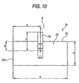
- the lug in an electrode structure has been bonded in the position shown in Fig. 10 in order to prevent the lug from coming into contact with the metallic battery case to cause internal short-circuiting.
- the lug 3 in the electrode structure 1 is bonded in such a position that the distance b between that shorter side 2a of the rectangular electrode which faces the center and the center line X of the lug 3 satisfies the following relationship with the length a of a longer side of the electrode: b ⁇ 0.4a.
- a subject for the invention which has been achieved in view of the drawbacks of related-art techniques described above, is to provide an alkaline storage battery which employs a hydrogen-storing-alloy electrode or cadmium electrode as a negative electrode and which has a high discharge capacity and has a high charging efficiency even in charging in an extremely short time, which has not been attained so far, without undergoing a decrease in the coefficient of active-material use or a decrease in charge/discharge cycle performance or in the function of inhibiting the internal battery pressure from increasing during overcharge or high-rate charging.
- Another subject is to provide a method of charging the battery.
- a further object thereof is to provide an electrode structure and a storage battery which each can attain improvement in suitability for rapid charging completed in 15-30 minutes, without lowering battery characteristics concerning smallness, high capacity, and cycle performance. It was found that the electrode structure produces surprising effects due to the lug bonding position therein which has been optimized, although this has not been attained with any technical idea in the related art. Those objects have been thus accomplished.
- the invention provides the following.
- the storage battery is a sealed alkaline storage battery which has the function of being capable of charge when the gas pressure in the battery and/or the battery temperature is not higher than a specified value and of being incapable of charge when the gas pressure in the battery and/or the battery temperature exceeds the specified value.
- the sealed alkaline storage battery is one in which the discharge capacity ratio between the negative electrode and the positive electrode (discharge capacity of the negative electrode/discharge capacity of the positive electrode) is 1.45 or lower
- the specified value of the gas pressure in the battery has been set at a value in the range of 0.5-1.0 MPa.
- the specified value of the gas pressure in the battery has been set at a value in the range of 1-3 MPa or the specified value of the battery temperature has been set at a value in the range of 50-80°C.
- the alkaline storage battery according to the invention can be inhibited from increasing in the gas pressure in the battery or increasing in battery temperature even when charged at such a high rate that charging is completed in 15 minutes to 30 minutes.
- the battery attains a high charging efficiency even when charged at such high rates.
- the sealed alkaline storage battery according to the invention is a sealed alkaline storage battery which has the function of being capable of charge when the gas pressure in the battery and/or the battery temperature is not higher than a specified value and of being incapable of charge when the gas pressure in the battery and/or the battery temperature exceeds the specified value, so as to attain a high capacity, and in which the proportion between the discharge capacity of the negative electrode and the discharge capacity of the positive electrode is 1.02-1.45.
- One of the processes according to the invention for producing the alkaline storage battery is a production process in which a powdery material comprising nickel hydroxide as the main component is oxidized by a chemical reaction or oxidized in an electrochemical manner to thereby regulate the average oxidation number of the transition metal elements contained in the powdery material to 2.04-2.4 and is then used as an active-material powder for a nickel electrode.
- the alkaline storage battery according to the invention can be a sealed alkaline storage battery in which the ratio between the capacity of the negative electrode to be incorporated in the battery and the capacity of the positive electrode to be likewise incorporated is set at a lower value than in the alkaline storage batteries heretofore in use and the oxidation number of the positive-electrode active material has been regulated beforehand so as to be higher than 2, whereby the formation of a discharge reserve is inhibited. Because of this, the sealed alkaline storage battery is inhibited from undergoing oxygen generation during charge and has a heightened charging efficiency in high-rate charging.
- the positive electrode may contain a compound containing at least one element selected from at least one rare-earth element selected from Ho, Er, Tm, Yb, Lu, and Y and from Ca.
- the sealed alkaline storage battery may be one in which the content of the rare-earth elements in the positive electrode has been regulated to 0.5-4% by weight in terms of element amount.
- the alkaline storage battery according to the invention may be a sealed alkaline storage battery which employs as a liquid electrolyte an aqueous alkali solution which contains potassium hydroxide as a major electrolyte and has a concentration of 7.5 ⁇ 1.5 mol/dm 3 , the liquid electrolyte being contained in an amount of 0.6-1.4 cm 3 per unit capacity (Ah) of the alkaline storage battery.
- the alkaline storage battery according to the invention may be a sealed alkaline storage battery employing as a separator a nonwoven fabric which comprises hydrophilic fibers having a fiber diameter of 0.5 deniers or finer as a major constituent material and which has a basis weight of 35-70 g/m 2 and preferably has a thickness of 70-120 ⁇ m.
- the alkaline storage battery according to the invention can be inhibited from undergoing oxygen generation at the positive electrode and hydrogen generation at the negative electrode during charge and can have a heightened charging efficiency in high-rate charging.
- the sealed alkaline storage battery according to the invention may be a sealed alkaline storage battery in which the negative electrode contains a catalyst which accelerates a reaction by which oxygen gas and/or hydrogen gas is absorbed.
- the catalyst are metallic materials such as Raney nickel and Raney cobalt.
- the other process according to the invention for producing a sealed alkaline storage battery is a process for producing a sealed alkaline storage battery including a negative electrode to which a powder of a hydrogen-storing alloy has been applied.
- the hydrogen-storing alloy is immersed in an alkaline aqueous solution or acid aqueous solution before being incorporated into the battery to thereby heighten the activity thereof.
- a sealed alkaline storage battery which has the enhanced ability to absorb the oxygen gas and hydrogen gas generating during charge and which is inhibited from increasing in internal pressure in high-rate charging.
- the sealed alkaline storage battery according to the invention may be a sealed alkaline storage battery in which the negative-electrode active material is a hydrogen-storing-alloy powder and the negative electrode contains at least one rare-earth element selected from Ho, Er, Tm, Yb, Lu, Y, and Ce.
- the corrosion resistance of the hydrogen-storing alloy in the alkaline liquid electrolyte can be enhanced and the sealed alkaline storage battery can have excellent cycle performance even in repetitions of high-rate charging.
- the method according to the invention for charging the sealed alkaline storage battery is a charging method in which when the internal pressure and/or temperature of the battery being charged is not higher than a specified value, the charging is conducted, and when the internal pressure and/or temperature of the battery exceeds the specified value, the charging is stopped.
- Charging modes for the sealed alkaline storage battery according to the invention are not particularly limited, and use can be made of constant-voltage charge, constant-current charge, constant-power charge, and a combination of these.
- a mode in which the charging current decreases with the progress of charge and becomes low in a final stage of charge has an advantage that the change in battery temperature which accompanies on/off switching of charge can be small. From this standpoint, constant-voltage charge is preferred.
- the charging method may be the method of charging at a constant voltage in which the charging voltage is set at a value of the range of 1.5-1.7 V.
- charging can be completed in a time period as short as 15-30 minutes and the gas pressure in the battery and the battery temperature can be inhibited from increasing.
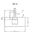
- the invention further provides an electrode structure characterized by comprising: an electrode substrate obtained by impregnating with an active material a porous substrate which has a rectangular shape with a longer-direction width of a and a shorter-direction width of ⁇ and is capable of being spirally wound, with one of the shorter sides facing toward the center; and a single lug bonded to the electrode substrate, the lug having been bonded to the electrode substrate in such a position that the distance b between that one shorter side of the electrode substrate and the center line of the lug satisfies 0.3a ⁇ b ⁇ 0.6a.
- the active material present in those parts of the electrode which are remote from the lug does not participate in the reactions and, hence, the charging efficiency is low.
- the charging current is concentrated in parts close to the lug and these parts have an increased current density. Because of this, the charging of the active material proceeds too slowly and side reactions such as the decomposition reaction of the liquid electrolyte occur, resulting in a decrease in charging efficiency.
- the electrode structure of the invention attains an improved charging efficiency because the distance b indicating the lug bonding position has been regulated so as to satisfy 0.3a ⁇ b ⁇ 0.6a and this not only enables the active material present in electrode parts remote from the lug to participate in reactions but also prevents the charging current from concentrating in electrode parts close to the lug to thereby inhibit side reactions.
- the invention produces especially marked effects when the electrode structure improved in lug bonding position is combined with a pressure switch function.
- the lug has a shorter-direction width and a longer-direction width, which are widths as measured respectively along the longer direction and shorter direction for the electrode substrate, of c and ⁇ , respectively, and that region of the lug which overlaps the electrode substrate has a length of ⁇ , the a, c, ⁇ , ⁇ , and ⁇ satisfying the following. 0.02 ⁇ c/a ⁇ 0.07 0.065 ⁇ / ⁇ 0.45 0.1 ⁇ / ⁇ 0.75
- the region in which the lug overlaps the electrode substrate has a shape similar to the outer shape of the electrode substrate.
- the lug is bonded to the electrode substrate by welding.
- the welding is spot welding conducted on spots radially arranged around the point of intersection of the center line of the lug and that longer side of the electrode substrate to which the lug is bonded.
- the invention furthermore provides a storage battery having the electrode structure of any of the constitutions described above.
- Fig. 1 is a sectional view diagrammatically illustrating a section of an important part of a sealed alkaline storage battery 1 according to one embodiment of the invention.
- a wound element obtained by superposing and winding a strip-form positive electrode plate 2 and a strip-form negative electrode plate 3 together with strip-form separators 4 interposed therebetween so that the outermost lap is the negative electrode plate 3 is packed in a cylindrical metallic battery case 5.
- the negative electrode plate located as the outermost lap of the wound element is brought into contact with the inner surface of the side wall of the battery case 5 (although the figure shows a gap between the negative electrode plate and the inner surface of the battery case, these two are actually in contact with each other) to thereby electrically connect the negative electrode plate to the battery case 5.
- a liquid electrolyte comprising an aqueous solution of an electrolyte comprising KOH as the main component is introduced.
- a metallic lid 8 is fitted to the upper opening end of the battery case 5 through a gasket 9 made of a synthetic resin such as, e.g., nylon to thereby gastightly seal the battery case 5.
- a gasket 9 made of a synthetic resin such as, e.g., nylon to thereby gastightly seal the battery case 5.
- An electrolyte comprising KOH as the main component and further containing LiOH or NaOH is also applicable.
- the lid 8 has a through-hole 10 formed in a central part thereof, and a safety vent 11 made of rubber inserted between the lid 8 and a cap 12 is pressed against the through-hole 10 to gastightly seal the through-hole 10.
- a safety vent 11 made of rubber inserted between the lid 8 and a cap 12 is pressed against the through-hole 10 to gastightly seal the through-hole 10.
- the metallic lid 8 is equipped with a pressure switch inside.
- the pressure switch comprises: a metallic cover 15; a metallic rigid plate 17; a metallic thin plate 18; a gasket 19 which serves to gastightly seal the space surrounded by the metallic rigid plate 17 and the metallic thin plate 18 and to insulate the metallic rigid plate 17 and metallic thin plate 18 from the cover 15; and a spring 20 enclosed in the space surrounded by the metallic rigid plate 17 and the metallic thin plate 18.
- a peripheral part of the cover 15 has been bonded to the inner surface of the lid 8 and a through-hole 20 has been formed.
- the metallic thin plate 18 In an ordinary state (the state in which the gas pressure in the battery remains low), the metallic thin plate 18 is in contact with the lid 8 in the state of being electrically connected therewith.
- the gas pressure in the battery has increased, the gas pushes down the metallic thin plate 18 while opposing the elasticity of the spring 20. Namely, the metallic thin plate 18 separates from the lid 8 when the gas pressure in the battery exceeds a specified value. The electrical connection is hence eliminated.
- the metallic thin plate 18 When the gas pressure in the battery has decreased, the metallic thin plate 18 is pushed up due to the elasticity of the spring and the metallic thin plate 18 comes into contact with the lid 8 again, whereby the electrical connection between these is recovered.
- a function is imparted in which when the gas pressure in the battery has increased during charge, the charging is made off and when the gas pressure in the battery has decreased, charging is made on (hereinafter referred to as pressure switch function).
- Fig. 8 and Fig. 9 are presentations diagrammatically showing the charging current and battery temperature behaviors during charge of sealed storage batteries according to the invention when the charge on/off switch function worked.
- To make charging off herein preferably is an operation in which the charging is completely stopped (charging current is 0 A) in the charge-off period as shown in Fig. 8.
- Charging current is 0 A
- a charging current which has not decreased to 0 A may be kept flowing in a such a degree that the internal pressure or temperature of the battery does not increase beyond a specified value, as shown in Fig. 9.
- the charging current does not become 0 A even in the off period and a low current is kept flowing.
- the example shown in Fig. 1 is equipped with a temperature switch besides the pressure switch.
- Numeral 14 in the figure denotes a bimetal lead plate bonded to the positive-electrode current collector 6.
- the lead plate 14 In an ordinary state (the state in which the battery temperature remains low), the lead plate 14 is in contact with the metallic rigid plate 17 and electrical connection is maintained between these. When the temperature rises, the lead plate 14 deforms downward on the figure. When the temperature has risen beyond a specified value, the lead plate 14 separates from the metallic rigid plate 17 and the electrical connection between these is eliminated. When the temperature lowers, the lead plate 14 recovers its original shape and, hence, the electrical connection between the two is recovered.
- temperature switch function a function is imparted in which when the battery temperature has risen during charge, the charging is made off and when the battery temperature has lowered, charging is made on (hereinafter referred to as temperature switch function).
- the position in which the bimetal lead plate is disposed is not particularly limited as long as the lead plate is disposed so as to be incorporated in the circuit.
- the temperature of the current collector which is directly bonded to the electrode plate, most precisely reflects the internal temperature of the battery, it is preferred to bond the lead plate to the current collector as in the embodiment shown in Fig. 1.
- Polyswitch (PTC element) is incorporated, in place of the bimetal lead plate, into the circuit extending from the current collector 6 to the lid 9.
- This element is an element whose electrical resistance increases abruptly when the temperature thereof exceeds a given value.
- the electrical resistance of the element should increase abruptly at a temperature of 50-80°C and the electrical resistance value after the increase be on the order of kilohms (k ⁇ ) or higher.
- the resistance increase of the electric circuit can make the charging substantially impossible.
- the specified value for charge stopping which is based on internal gas pressure is not higher than the opening pressure for the safety vent 11 made of rubber and is set so that battery performance deterioration can be inhibited.
- the specified value is preferably set at 1.0 MPa to 3.0 MPa, more preferably set at 1.5-2.5 MPa.
- the specified value for charge stopping which is based on battery temperature is preferably 50-80°C, more preferably 60-80°C.
- set value is lower than 50°C
- charge reception in high-rate charging is reduced.
- set values exceeding 80°C lead to alteration of the hydrogen-storing alloy, separators, and binders in the positive and negative electrodes and this may lead to deterioration of the discharge capacity or cycle life of the storage battery.
- the term battery temperature as used in the invention means the temperature of inner parts of the battery.
- the temperature of a battery surface in particular, the temperature of a side or bottom surface of the metallic case, can be used in place of the internal temperature. Since the side or bottom surface of the battery case is in contact with the element and the metallic case has high thermal conductivity, the temperature thereof well reflects the internal temperature of the battery.
- the alkaline storage battery according to the invention has both a pressure switch function and a temperature switch function. In case where one of the two functions develops a trouble, the battery having the two functions is satisfactorily used as long as the other function has no trouble.
- the battery need not always have both a pressure switch function and a temperature switch function.
- the battery may have either of the two functions.
- a temperature switch function has the following drawback. In case where local heating has occurred in a specific part in the battery, it is difficult for the function to sharply sense the heating. Especially when the battery is large, there is a possibility that the temperature in the battery might differ from part to part and it is difficult to sharply sense the state of heating.
- the temperature of a battery surface may be used as the battery temperature in the invention.
- a temperature switch function can be imparted not to the battery but to a charger, and this is rather preferred.
- a temperature sensor is attached to that part of the charger which comes into contact with a surface, preferably a side or bottom surface, of the battery to be charged, and the function of changing between charging on and charging off according to the detected battery temperature is imparted to the charger, whereby the battery temperature is prevented from exceeding a specified value during charge.
- the positive-electrode material powder to be applied to the positive electrode of the alkaline storage battery according to the invention desirably comprises nickel hydroxide, which is an active material, as the main component and contains a small amount of at least one element selected from zinc (Zn), cobalt (Co), magnesium (Mg), copper (Cu), and barium (Ba) in a solid solution state.
- the zinc (Zn), magnesium (Mg), copper (Cu), or barium (Ba) in the form of a solid solution in nickel hydroxide has the effect of inhibiting ⁇ -NiOOH, which is inert as an active material, from generating when the battery is subjected to charge/discharge.
- the solid solution of cobalt has the effect of shifting the charging potential of the nickel electrode to the less noble side and thereby inhibiting oxygen from generating at the nickel electrode during charge.
- a solid solution in the nickel hydroxide is especially effective.
- a solid solution (powdery material) of 1-7% by weight zinc and 1-5% by weight cobalt, in terms of element amount, in nickel hydroxide is applied.
- the positive-electrode active-material powder to be applied to the invention preferably is one obtained by forming a coating layer comprising a cobalt-containing compound, e.g., cobalt hydroxide, on the surface of the nickel hydroxide containing a small amount of zinc, cobalt, etc. in a solid solution state.
- a cobalt-containing compound e.g., cobalt hydroxide
- the proportion of the surface coating layer comprising a cobalt compound in the whole positive-electrode active-material powder is preferably regulated to 1-7% by weight in terms of elementary cobalt.
- the positive-electrode active-material powder to be applied to the invention preferably is a high-density powder which has been synthesized by the amine complex method, a known method for synthesizing positive-electrode active-material powders, and has a nearly spherical shape and a tap density of 2.0 or higher.
- a positive electrode in which the density of the positive-electrode active material used for impregnation is high and which has a high coefficient of active-material use and a high charging efficiency in high-rate charging.
- the nickel hydroxide-based active-material powder to be applied to the first sealed alkaline storage battery according to the invention preferably is one in which the average oxidation number of the transition metal elements (Ni and Co) contained therein is preferably 2.04-2.40, more preferably 2.07-2.30.
- Specific methods for increasing the average oxidation number of the transition metal elements contained in the active-material powder to 2.04-2.40 are not particularly limited.
- to chemically oxidize the active-material powder with an oxidizing agent in the presence of an aqueous alkali solution is a simple method suitable for mass production. This is a preferred production process.
- the active-material powder is oxidized at a temperature of 90°C with an oxidizing agent such as, e.g., NaClO or K 2 S 2 O 8 in an aqueous NaOH solution having a concentration of 10% by weight.
- an oxidizing agent such as, e.g., NaClO or K 2 S 2 O 8 in an aqueous NaOH solution having a concentration of 10% by weight.
- the average oxidation number of the transition metals contained in the active material can be easily controlled by regulating the proportion of the active-material powder to the oxidizing agent.
- Another method comprises impregnating a porous substrate such as foamed nickel with a powdery material comprising nickel hydroxide as the main component and then electrochemically oxidizing the powdery material with an aqueous solution of potassium hydroxide, sodium hydroxide, or the like as a liquid electrolyte to thereby produce the positive-electrode active-material powder.
- the average oxidation number of the transition metal elements contained in the active material can be controlled by regulating the quantity of electricity applied.
- the positive electrode be used as the only electrode and charged or charging be conducted in the following manner.
- the positive electrode and a negative electrode are incorporated into a battery and the positive electrode is then charged in an open state.
- the battery is subjected to continuous suction for about 1 hour so that the pressure of the atmosphere is kept at 0.01 MPa or lower to thereby remove the hydrogen occluded in the negative electrode as a result of the charging.
- part of the nickel hydroxide becomes nickel oxyhydroxide consisting mainly of the ⁇ -form.
- the positive-electrode active-material powder obtained contains a higher-order cobalt compound containing alkali cations and having disordered crystallinity; this cobalt compound has been formed by the oxidation treatment from the coating layer comprising a cobalt compound and disposed on the surface of the powder comprising nickel hydroxide as the main component. This can reduce the amount of a discharge reserve to be formed.
- To heighten the average oxidation number of the nickel hydroxide-based active-material powder to 2.04-2.40 as described above means to oxidize the cobalt in the surface coating layer as a component of the active-material powder to a higher-order cobalt compound in which the oxidation number of the cobalt is higher than 2 and, besides this, to oxidize part of the nickel and cobalt having an oxidation number of 2 contained in the core layer to higher-order compounds in which the oxidation number is higher than 2.
- the oxidation not only forms a layer of a higher-order cobalt compound having satisfactory conductivity on the surface of the active material to thereby heighten the coefficient of active-material use, but also can inhibit the formation of a discharge reserve. As a result, a large amount of a charge reserve can be secured. Consequently, hydrogen generation at the negative electrode during charge can be inhibited and the gas pressure in the battery can be inhibited from increasing.
- the oxidizing agent to be used for the oxidation treatment is not particularly limited, and use can be made of a chloric acid salt, hypochlorous acid salt, chlorous acid salt, peroxo acid salt, oxygen, or the like.
- the nickel electrode for the first sealed alkaline storage battery according to the invention preferably contains a compound (a hydroxide or hydrate thereof or an oxide) containing at least one element selected from at least one rare-earth element selected from Ho, Er, Tm, Yb, Lu, and Y and from Ca.
- the total content of the rare-earth elements is preferably 0.1-5% by weight, more preferably 0.5-4% by weight, in terms of the amount of the rare-earth elements or calcium. In case where the content of the rare-earth elements or calcium is lower than 0.1% by weight, the effect of inhibiting oxygen generation at the positive electrode is insufficient.
- the sealed nickel electrode according to the invention can be produced by filling on a porous substrate, e.g., foamed nickel, a positive-electrode material powder prepared by mixing the active-material powder having an average particle size of 5-20 ⁇ m with a powder of a hydroxide of the rare-earth element or a hydrate thereof or an oxide of the element, the latter powder having almost the same size as or a smaller size than the former powder.
- a porous substrate e.g., foamed nickel
- a positive-electrode material powder prepared by mixing the active-material powder having an average particle size of 5-20 ⁇ m with a powder of a hydroxide of the rare-earth element or a hydrate thereof or an oxide of the element, the latter powder having almost the same size as or a smaller size than the former powder.
- a two-dimensional porous object such as a perforated plate or a three-dimensional one obtained by forming projections or irregularities on the surfaces of the two-dimensional porous object can be used as the porous substrate.
- the negative electrode for the alkaline storage battery according to the invention is one obtained by filling an active material which is a hydrogen-storing alloy powder or a cadmium oxide or cadmium hydroxide powder on a perforated plate formed from a metallic sheet material such as, e.g., nickel or a nickel-plated steel sheet.
- the hydrogen-storing alloy powder or the cadmium oxide or cadmium hydroxide powder preferably has an average particle diameter of 15-55 ⁇ m. In case where the average particle diameter of the powder is smaller than 15 ⁇ m, the powder is apt to be corroded and the corrosion may lead to a performance decrease.
- the hydrogen-storing alloy to be applied to the negative electrode of the alkaline storage battery according to the invention preferably comprises one or more members selected from the group consisting of AB5 type alloys having the CaCu5 type structure, AB 2 type alloys having the Laves phase structure (MgCu 2 type or MgZn 2 type), AB type alloys having the CsCl type structure, and A 2 B type alloys having the Mg 2 Ni type structure.
- the negative electrode of the first sealed alkaline storage battery according to the invention preferably contains a catalyst which promotes a reaction for absorbing hydrogen or oxygen.
- the material of the catalyst is not particularly limited, and a noble-metal element such as platinum or palladium may be used.
- an inexpensive material such as Raney nickel or Raney cobalt is more preferred.
- a powder having an average particle diameter of 1-10 ⁇ m is preferred which has been produced by subjecting an alloy comprising 60-40% by weight nickel and 40-60% by weight aluminum or an alloy comprising 60-40% by weight cobalt and 40-60% by weight aluminum to a developing treatment with an aqueous alkali solution by a known method.
- the absorption of the hydrogen gas and oxygen gas generating at the negative electrode and positive electrode, respectively, during charge can be accelerated and the gas pressure in the battery can be inhibited from increasing.
- the hydrogen-storing alloy powder to be applied to the hydrogen-storing alloy electrode of the first sealed alkaline storage battery according to the invention may be immersed in an aqueous solution of an alkali, e.g., KOH, or a solution of an inorganic acid, e.g., hydrochloric acid, or organic acid, e.g., acetic acid, (processing liquid), whereby the coating film which has been formed on the surface of the powder and comprises an oxide, hydroxide, or another compound of a metal contained as a component in the hydrogen-storing alloy is dissolved away to enhance the activity of the hydrogen-storing alloy powder.
- an alkali e.g., KOH
- an inorganic acid e.g., hydrochloric acid
- organic acid e.g., acetic acid
- a complexing agent such as, e.g., ethylenediamine tetraacetate (EDTA) or tartaric acid may be added in a small amount to the processing liquid.
- EDTA ethylenediamine tetraacetate
- tartaric acid may be added in a small amount to the processing liquid. This is more preferred because it has the effect of enhancing the stability of the transition metal element which has dissolved away during the immersion treatment in the processing liquid and preventing the transition metal element which has dissolved away from re-depositing as a hydroxide part on the surface of the hydrogen-storing alloy powder.
- the hydrogen-storing alloy electrode of the first sealed alkaline storage battery according to the invention preferably contains at least one rare-earth element selected from Ho, Er, Tm, Yb, Lu, Y, and Ce.
- rare-earth elements may be present as an alloy within the structure of the hydrogen-storing alloy, it is more preferred that these elements be present outside the structure of the hydrogen-storing alloy as the elemental metals or as hydroxides or oxides. These rare-earth elements serve to enhance the corrosion resistance of the hydrogen-storing alloy in an alkaline liquid electrolyte and thereby prevent the hydrogen-storing alloy from corroding during charge due to the presence of oxygen generating at the positive electrode or to an increased battery temperature.
- outside the structure of the hydrogen-storing alloy herein means that the elements are present not in inner parts of the hydrogen-storing alloy powder but outside the hydrogen-storing alloy powder.
- the surface cracks and the spaces among primary particles are regarded as outside the structure of the hydrogen-storing alloy powder.
- separators according to the invention can be used, for example, a nonwoven fabric obtained by hydrophilizing a nonwoven fabric made of polyethylene, polypropylene, or polyethylene/polypropylene by reacting it with sulfur trioxide in a gas phase to incorporate sulfo groups onto the fiber surface (sulfonation treatment) or by graft-polymerizing hydrophilic groups such as acrylic acid with the fibers.
- nonwoven fabric constituted of fine fibers having a fiber diameter of 0.5 deniers or smaller. This is because separators comprising this nonwoven fabric have fine pores, an even pore size, and satisfactory liquid retention.
- the value in denier indicates the proportion of the weight of the fiber having a length of 450 m to 0.5 g.
- a nonwoven fabric constituted of fine fibers obtained by splitting split fibers produced by multi-component fiber spinning from a first ingredient comprising a polyolefin, e.g., polypropylene, and a second ingredient comprising an ethylene/vinyl alcohol copolymer into the components is suitable for use as a major constituent material for separators because it has the property of retaining excellent hydrophilicity over long.
- the oxygen which has generated at the positive electrode during charge is absorbed in the negative electrode.
- the basis weight of the separators in the invention is preferably 35-70 g/m 2 , more preferably 40-60 g/m 2 .
- each separator is preferably 50-120 ⁇ m, more preferably 80-110 ⁇ m.
- the thickness of a separator herein means the value obtained through a measurement made in accordance with method A (for general nonwoven fabrics) among the thickness test methods as provided for in Japanese Industrial Standard (JIS) L1913 (testing methods for general fibers/nonwoven fabrics).
- the element of the nickel/metal-hydride storage battery according to the invention is one comprising the positive electrode (nickel electrode) and the negative electrode (hydrogen-storing alloy electrode or cadmium electrode) which have been stacked together with a separator interposed therebetween.
- the capacity ratio between the negative electrode and positive electrode constituting the element ⁇ N/P ratio ⁇ is regulated to preferably 1.02-1.45, more preferably 1.1-1.45.
- That value is lower than the values of 1.5-1.8 for alkaline storage batteries heretofore in use.
- N/P ratio is lower than 1.02, high-rate discharge characteristics and the charging efficiency in high-rate charging decrease. Conversely, N/P ratios exceeding 1.45 result in a battery having a reduced discharge capacity.
- capacity of a negative electrode and “capacity of a positive electrode” herein mean the discharge capacity determined when the positive electrode and the negative electrode each are subjected to a single-electrode test at a temperature of 20°C.
- a method of the single-electrode test in the case of the single-electrode test of a positive electrode, for example, is as follows. The positive electrode is stacked through a separator on a negative electrode having a large excess of capacity, and this assembly is tightly pressed.
- a test battery (open battery) containing an aqueous KOH solution having a density of 1.3 g/cm 3 as a liquid electrolyte is prepared.
- a mercuric oxide electrode (Hg/HgO electrode), for example, is incorporated into the battery as a reference electrode for measuring the potential of the positive electrode.
- the battery is charged for 16 hours at a current of 0.1 ItA based on the impregnant capacity of the positive electrode. After a subsequent 1-hour pause, the battery is discharged at the same current as in the charging until the potential of the positive electrode reaches 0 mV versus the reference electrode. This charge/discharge operation is repeated until the discharge capacity of the positive electrode becomes constant. The value of discharge capacity as measured at the time when the capacity became constant was taken as the capacity of the positive electrode.
- a test battery including the negative electrode combined through a separator with a positive electrode having a large excess of capacity (open battery; having the same constitution as in the single-electrode test of a positive electrode, except that the capacity of the positive electrode was in large excess based on the capacity of the negative electrode) is prepared.
- the battery is charged for 16 hours at a current of 0.1 ItA based on the impregnant capacity of the negative electrode. After a subsequent 1-hour pause, the battery is discharged at the same current as in the charging until the potential of the negative electrode reaches -600 mV versus the oxide reference electrode (Hg/HgO electrode).
- This charge/discharge operation is repeated until the discharge capacity of the negative electrode becomes constant.
- the value of discharge capacity as measured at the time when the capacity became constant was taken as the capacity of the negative electrode.
- the alkaline storage battery according to the invention is a sealed battery which includes, packed in a closed space, a power-generating element comprising an element obtained by superposing a positive electrode, separators, and a negative electrode and a liquid electrolyte.
- the power-generating element is packed, for example, in a metallic battery case serving also as a negative-electrode terminal, and the upper opening end of the battery case is sealed with a metallic lid serving also as a positive-electrode terminal.
- the battery case and the lid is electrically insulated from each other with a gasket interposed between these and made of a synthetic resin, and the gap between the battery case and the lid is gastightly sealed with the gasket.
- a positive-electrode current collector has been bonded to the positive electrode, and the lid and the positive-electrode current collector have been electrically connected to each other with a positive-electrode lead plate.
- a negative-electrode current collector has been bonded to the negative electrode, and the negative-electrode current collector is bonded to the battery case.
- the charging, charging interruption, and restarting of charging are repeatedly conducted.
- modes of charging according to the invention are not particularly limited, constant-voltage charging is preferred as stated above.
- a positive-electrode active-material powder consisting mainly of nickel hydroxide was produced by a known method.
- the pH and temperature of the reaction bath were regulated so as to be within those ranges.
- a nickel hydroxide powder containing zinc hydroxide and cobalt hydroxide in a solid solution state was yielded.
- the proportions of the zinc and cobalt contained in the powder were regulated to 3% by weight and 2% by weight, respectively, in terms of metal proportion.
- the nickel hydroxide powder was immersed in an aqueous sodium hydroxide solution whose pH and temperature were set at the same values as those shown above. While stirring this solution, an aqueous cobalt sulfate solution and an aqueous sodium hydroxide solution were gradually added thereto. During this addition, the pH and temperature of the reaction bath were regulated so as to be within those ranges.
- an active-material powder having an average particle diameter of 10 ⁇ m and a spherical shape which comprised the powder consisting mainly of nickel hydroxide and, formed on the surface of the powder, a coating layer comprising cobalt hydroxide.
- a positive-electrode active-material powder was thus obtained.
- the proportion of the coating film in the nickel hydroxide-based active-material powder was regulated to 4% by mass.
- a hundred grams of the nickel hydroxide-based active-material powder was added to 400 cm 3 of an aqueous NaOH solution which had a concentration of 10% by weight and was kept at a temperature of 50°C. While the solution was being stirred for dispersion, 45 cm 3 of a solution of an oxidizing agent (NaClO; effective concentration, 10%) was added thereto.
- an oxidizing agent NaClO; effective concentration, 10%
- the resultant mixture was continuously stirred for 1 hour. Subsequently, the powder was taken out by filtration, washed with water, and then dried in air at a temperature of 80°C.
- the powder was washed with water and then dried at a temperature of 80°C for 1 hour to obtain a positive-electrode active-material powder.
- Ten grams of the active material obtained was introduced into a measuring cylinder having a capacity of 10 cm 3 , which was then allowed to fall naturally from a height of 10 cm on a table made of a hard rubber.
- the falling operation was repeatedly conducted 100 times to measure the tap density.
- the tap density of the active-material powder obtained was 2.1.
- the average oxidation number of the positive-electrode active-material powder was determined by the ferrous sulfate method.
- the positive-electrode active material (sample) and about 1 g of ammonium ferrous sulfate were weighed out and added to an aqueous acetic acid solution which had a concentration of 20% by volume and the temperature of which was set at 5°C. The solution was stirred for about 5 hours to completely dissolve the sample and the ammonium ferrous sulfate. Thereafter, the resultant solution was titrated with an aqueous potassium permanganate solution having a concentration of 0.02 mol/dm 3 .
- the active-oxygen amount (mg) in the sample was determined using the following equation.
- Xsp is the weighed amount of the sample (g)
- XFe is the weighed amount of the ammonium ferrous sulfate (g)
- V is the amount of the aqueous potassium permanganate solution used for titration (cm 3 )
- f is the factor of the aqueous potassium permanganate solution
- 392.14 is the molecular weight of ammonium ferrous sulfate.
- the amounts of the nickel and cobalt (mg) contained in the sample powder were determined, for example, by ICP emission spectral analysis, and the average oxidation number of the positive-electrode active-material powder was determined using the following equation.
- the term average oxidation number herein means the average oxidation number of the nickel and cobalt contained in the positive-electrode active-material powder.
- the average oxidation number of the nickel and cobalt contained in the active material obtained was 2.15.
- the numeral 16000 indicates (atomic weight of oxygen) ⁇ 1000
- numeral 58690 indicates (atomic weight of nickel) ⁇ 1000
- numeral 58933.2 indicates (atomic weight of cobalt) ⁇ 1000.
- a Yb 2 O 3 powder having an average particle diameter of 1 ⁇ m was added to 100 g of the active-material powder which had undergone the heat treatment.
- the ingredients were mixed by means of a mixer until they became homogeneous. Thus, a powdery material for positive-electrode formation was obtained.
- the proportion of the Yb 2 O 3 powder to be added was regulated so that the proportion of ytterbium contained in the powdery material for positive-electrode formation became 2% by weight in terms of elemental ytterbium amount.
- Eighty parts by weight of the powdery material for positive-electrode formation was mixed with 20 parts by weight of an aqueous carboxymethyl cellulose (CMC) solution having a concentration of 0.5% by weight to prepare a paste.
- CMC carboxymethyl cellulose
- a strip-form porous substrate made of nickel having a thickness of 1.5 mm and a porosity of 95% was coated and impregnated with the paste. This substrate was dried to remove the water in the paste and then pressed with pressure rolls. Thus, a strip-form raw sheet for nickel electrodes was produced which had a thickness of 0.8 mm. The raw sheet was cut into a given size to obtain a nickel electrode for a cylindrical battery (AA size).
- the nickel electrode obtained had an active-material impregnant capacity of 2,000 mAh.
- a hydrogen-storing alloy powder having a composition represented by MmNi3.6Co0.7Mn0.4Al0.3 (wherein Mm indicates a mischmetal comprising a mixture of rare-earth elements, e.g., La, Ce, Pr, Nd, and Sm) and an average particle diameter of 30 ⁇ m.
- the positive electrode and the negative electrode were stacked together with separators interposed therebetween, the separators comprising a nonwoven polypropylene fabric which was constituted of fibers made of a copolymer of ethylene and propylene in a ratio of 1/1, having a fiber diameter of 0.2 deniers, and having sulfo groups incorporated therein through gas-phase reaction with sulfur trioxide by a known method and which had a basis weight of 50 g/m 2 and a thickness of 100 ⁇ m.
- This assembly was wound to obtain an element in which the outermost lap was the negative electrode.
- the proportion of the sulfo groups incorporated (hereinafter referred to as the degree of sulfonation) was regulated to 1.3% by weight.
- a positive-electrode current collector was bonded to the upper side of the wound element by series spot welding. This element was inserted into a cylindrical metallic battery case, and that part of the negative electrode which constituted the outermost lap of the wound element was brought into contact with the metallic battery case.
- a positive-electrode lead plate made of nickel was bonded to the positive-electrode current collector as shown in Fig. 1, and 1.7 cm 3 of an aqueous solution containing 7 mol/dm 3 potassium hydroxide and 0.5 mol/dm 3 lithium hydroxide was filled.
- the degree of sulfonation of the fibers used as the separators in this Example was regulated to 1.3% by weight, the degree of sulfonation in the battery according to the invention should not be construed as being limited to that.
- the degree of sulfonation is preferably 0.5-2% by weight.
- the fibers In case where that proportion is below 0.5% by weight, the fibers have poor hydrophilicity and the separators have low liquid retention.
- the amount of sulfur contained in the separators was determined by fluorescent X-ray spectroscopy. The found value was converted to the amount per 1 m 2 (g/m 2 ), and the proportion (%) of this converted value to the basis weight of the separators was taken as the degree of sulfonation.
- a lid having a pressure switch attached to the inner side thereof as shown in Fig. 1 was applied and the positive-electrode lead plate was contacted with the metallic rigid plate of the pressure switch.
- This battery case was sealed in a given manner to produce a sealed battery of the AA size.
- the operating pressure for the pressure switch (the pressure at which the charging circuit is made off as stated above) was set at 2 MPa. A temperature switch function was not imparted in this Example. Incidentally, the operating pressure for the safety vent (the internal battery pressure at which the gastightly sealed state is broken and the gas present inside is discharged outside through the through-hole 10 shown in Fig. 1) was regulated to 3.5 MPa.
- Example 2 The same constitution as in Example 1 was employed, except that springs differing in modulus of elasticity were used to change the specified operating pressure for the pressure switch to 0.7 MPa, 1 MPa, 3 MPa, and 3.3 MPa, respectively.
- the batteries were referred to the batteries of Example 2, Example 3, Example 4, and Example 5, respectively.
- Example 2 The same constitution as in Example 1 was employed, except that a lid having no pressure switch was used and the positive-electrode current collector and the lid was directly connected to each other with a strip-form lead plate made of nickel.
- This battery is referred to as the battery of Comparative Example 1.
- Ten sealed alkaline storage batteries were prepared with respect to each of the batteries of Examples 1 to 5 and Comparative Example 1. The batteries were allowed to stand at a temperature of 20°C for 3 hours and then subjected to forming at a temperature of 20°C.
- a first charge was conducted at a current of 0.05 ItA for 20 hours and subsequently a first discharge was conducted at a current of 0.2 ItA to a cut-off voltage of 1.0 V.
- a temperature sensor for measuring the temperature of the side of a battery was attached to each of batteries which had undergone the forming described above. Thereafter, in an atmosphere having a temperature of 20°C, the batteries were charged at a current of 0.1 ItA for 16 hours and, after a 1-hour pause, discharged at a current of 0.2 ItA to a cut-off voltage of 1.0 V.
- the discharge capacity obtained in this discharge (average for ten batteries) is referred to as K (mAh).
- the ten batteries for each Example or Comparative Example were divided into two groups each consisting of five batteries.
- the two groups of five batteries were charged respectively at ambient temperatures of 20°C and 45°C for 15 minutes by applying a constant voltage of 1.65 V thereto.
- the batteries were discharged at a current of 0.2 ItA to a cut-off voltage of 1.0 V.
- the maximum temperature of the battery surfaces during this discharge was taken as the maximum temperature of the battery surface.
- Fig. 2 are shown the changes with time of the internal pressure of each of the battery of Example 1 and the battery of Comparative Example 1 in 15-minute charging at a charging voltage of 1.65 V and an ambient temperature of 20°C.
- Fig. 3 are shown the changes of the battery side surface temperatures with time in the charging.
- the batteries of Examples 1 to 5 and the battery of Comparative Example 1 are substantially equal in the discharge capacity ⁇ K(mAh) ⁇ determined after the ordinary constant-current charging (16-hour charging at 0.1 ItA). However, with respect to the charging efficiency determined in 15-minute charging at a constant voltage of 1.65 V, the performances of the batteries of the Examples are considerably higher than the performance of the battery of Comparative Example 1.
- Example 1 In the case where the batteries were charged for 15 minutes at a constant voltage of 1.65 V and a temperature of 20°C, the charging efficiencies in Example 1, Example 3, and Example 4 are higher by 10% or more than that in Comparative Example 1.
- Example 1 when the internal pressure of the battery has reached the specified value of 2 MPa, the pressure switch works to make the charging off. Thereafter, charging is alternately made on and off repeatedly and the battery can be further charged in an amount of 10% or more after the pressure switch worked first (the batteries of the other Examples show the same charge behavior).
- the battery temperature during charge is kept at 60°C or lower. A decrease in capacity due to property deterioration is not caused.
- the batteries of the Examples can attain a high charging efficiency.
- the batteries of Example 1, Example 3, and Example 4 are especially excellent in charging efficiency and cycle life. It can hence be seen that it is preferred to set the specified value of internal battery pressure at 1-3 MPa.
- the battery temperature continued to rise during charge and reached a temperature as high as 115°C just before the termination of charging.
- the battery of Comparative Example 1 has the defect of having a considerably reduced charging efficiency.
- Example 6 The same constitution as in Comparative Example 1 (having no pressure switch function) was employed, except that a temperature switch function only was imparted (the structure shown in Fig. 1 in which the pressure switch was omitted and one end of the bimetal positive-electrode lead plate was contacted with the inner side of the metallic lid to thereby electrically connect the positive electrode to the positive-electrode terminal) and that the temperature characteristics of the bimetal used as the positive-electrode lead plate were changed to set the operating temperatures for the temperature switch functions (the temperatures at which the charging circuit was made off) in Example 6 to Example 9 at 50°C, 60°C, 80°C, and 100°C, respectively.
- These batteries are referred to as the batteries of Example 6, Example 7, Example 8, and Example 9, respectively.
- a pressure sensor for measuring the gas pressure in a battery was attached to each of test batteries (ten batteries for each Example) of Examples 6 to 9 which had undergone forming in the same manner as described above.
- the ten batteries for each Example were divided into two groups each consisting of five batteries.
- the two groups of five batteries were charged respectively at ambient temperatures of 20°C and 45°C for 15 minutes at a charging voltage of 1.65 V.
- the maximum pressure in the batteries during this charge was taken as the maximum value of gas pressure in the battery (average for five batteries).
- the charging efficiency (average for five batteries, %) was determined in the same manner as in Battery Test 1. Thereafter, the same charge/discharge test as in Battery Test 1 was conducted to determine the cycle life (average for five batteries). The results of the tests are shown in Table 2.
- the batteries of Examples 6 to 9 each have a higher charging efficiency in 1.65-V constant-voltage charging than the battery of Comparative Example 1.
- the batteries of Examples 7 and 8 have a high charging efficiency in both charging at an ambient temperature of 20°C and charging at an ambient temperature of 45°C.
- the specified value of battery temperature is preferably 50-80°C, more preferably 60-80°C. It is thought that when the battery temperature exceeds 80°C during charge, oxygen generation at the positive electrode is enhanced and the hydrogen-storing ability of the negative electrode decreases, resulting in a reduced charging efficiency.
- Example 1 In Example 1 (with a pressure switch having an operating pressure of 2 MPa), a temperature switch having an operating temperature of 80°C was attached besides the pressure switch. The capacity of the positive electrode was fixed and the capacity of the negative electrode was varied to thereby change the N/P ratio in the range of 1.0-1.6.
- N/P negative-electrode capacity/positive-electrode capacity ratio
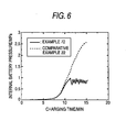
- a battery having the same constitution as the battery of Example 10 was produced, except that the pressure switch was omitted. This battery is referred to as the battery of Comparative Example 2.
- a battery having the same constitution as the battery of Example 13 was produced, except that the pressure switch was omitted. This battery is referred to as the battery of Comparative Example 3.
- the batteries were charged at a current of 0.1 ItA for 16 hours and, after a 1-hour pause, discharged at a current of 3 ItA to a cut-off voltage of 0.8 V.
- the discharge capacity obtained in this discharge is referred to as M (mAh).
- the ratio between the discharge capacities M and K ⁇ [M (mAh)/K (mAh)] ⁇ 100 (%) ⁇ was used as an index to high-rate discharge performance.
- test batteries of Examples 9 to 14 which had undergone forming in the same manner as described above were subjected at 20°C to the same tests as in Battery Test 1 to examine charging efficiency and cycle life. The results of the tests (average for five batteries) are shown in Table 3.
- Example batteries with a pressure switch function
- Comparative Example battery with no pressure switch function
- the battery having an N/P ratio of 1.2 has been markedly improved in charging efficiency and cycle performance by the impartation of the pressure switch function.
- the batteries of Examples 11 to 13 Compared to the battery of Example 10, which has an N/P ratio of 1, the batteries of Examples 11 to 13 have a higher value of M/K, which is an index to high-rate discharge performance, and a higher charging efficiency in 15-minute constant-voltage charging at 1.65 V.
- the batteries of Examples 12 and 13, which have an N/P ratio of 1.2-1.6, have excellent properties.
- the attainment of a high charging efficiency even in short-time charging and of excellent cycle performance as described above is attributable to the setting of the N/P ratio at a Value in the range of 1.02-1.6 and the impartation of a pressure switch function to the batteries.
- the negative-electrode plate has a large thickness because the amount of the negative-electrode active material used for impregnation is large.
- This constitution hence has a drawback that when wound elements are produced or batteries are fabricated, defectives are apt to be produced, resulting in a reduced yield.
- the N/P ratio is regulated to 1.02-1.45.
- Batteries were produced in the same manner as for the battery of Example 1, except that the amount of the oxidizing agent solution (NaClO; effective concentration, 10%) to be added for oxidizing the positive-electrode active-material powder was varied to thereby prepare positive-electrode active materials differing in oxidation number (average oxidation number of nickel and cobalt contained in the positive-electrode active material) and these positive-electrode active materials each were used.
- the oxidizing agent solution NaClO; effective concentration, 10%
- batteries respectively employing positive-electrode active materials having average oxidation numbers of 2.0, 2.04, 2.07, 2.3, 2.4, and 2.5 were produced.
- a battery having the same constitution as the battery of Example 14 was produced, except that the pressure switch was omitted. This battery is referred to as the battery of Comparative Example 4.
- a battery having the same constitution as the battery of Example 19 was produced, except that the pressure switch was omitted. This battery is referred to as the battery of Comparative Example 5.
- the discharge capacity obtained in this discharge is referred to as K (mAh).
- a pressure sensor for measuring the internal pressure of a battery was attached to the batteries, and the internal pressure of each battery was measured when the battery was charged at a current of 1 ItA and an ambient temperature of 20°C for 1 hour.
- Example batteries with a pressure switch function
- Comparative Example battery with no pressure switch function
- Table 4 shows that the following can be found when each of Example batteries (with a pressure switch function) is compared with the Comparative Example battery (with no pressure switch function) having the same average oxidation number of transition metal elements contained in the positive-electrode active material as the Example battery.
- the battery having an average oxidation number of 2.0 the battery having an average oxidation number of 2.15 has been markedly improved in charging efficiency in 15-minute charging at 1.65 V and in cycle performance.
- the batteries of Example 1 and Examples 15 to 19 are more inhibited from increasing in internal battery pressure in 1-hour charging at 1 ItA.
- the attainment of a high charging efficiency in charging for a period as short as 15 minutes and of excellent cycle performance in Examples 15 to 19 is attributable to the setting of the average oxidation number at a value in the range of 2.04-2.5 and the impartation of a pressure switch function to the batteries.
- the batteries of Examples 12 and 16 to 19, in particular the batteries of Examples 12, 17, and 18, are especially excellent in the effect of inhibiting internal-pressure increase and in charging efficiency and cycle performance.
- the positive-electrode active material before being incorporated into a battery, has an oxidation number of preferably 2.04-2.4, more preferably 2.07-2.3.
- Positive electrodes were produced in the same manner as in Example 1, except that the chemical oxidation treatment and alkali treatment of the positive-electrode active-material powder were omitted.
- An open battery was fabricated using each positive electrode and a nickel plate as a counter electrode and using 7.5 mol/dm 3 aqueous KOH solution as a liquid electrolyte. Charging was conducted for 7.5 hours at 1/50 ItA based on the capacity of the positive electrode. After the charging, the positive electrode was recovered, washed with water, and dried. Ten positive electrodes were thus prepared. The active-material powder was recovered from five positive electrodes, and the average oxidation number of the nickel and cobalt contained in this active material was determined by the same method as described above.
- Example 20 The remaining five electrodes were used to fabricate batteries in the same manner as in Example 1, and the batteries were subjected to forming. These batteries are referred to as the battery of Example 20.
- Positive electrodes were produced in the same manner as in Example 1, except that the chemical oxidation treatment and alkali treatment of the positive-electrode active-material powder were omitted.
- the average oxidation number of the nickel and cobalt contained in the active-material powder of the positive electrodes was determined in the same manner as in Example 1. The remaining five batteries were placed in a sealed vessel, which was continuously sucked for 1 hour.
- the pressure in the sealed vessel was kept at 0.01 ⁇ MPa or lower.
- a battery having the same constitution as the battery of Example 20 was produced, except that the pressure switch was omitted. This battery is referred to as the battery of Comparative Example 6.
- the batteries of Examples 20 and 21 are superior to the battery of Example 14 and comparable to the battery of Example 1 in the function of inhibiting the internal pressure of the battery from increasing during charge and in charging efficiency and cycle performance.
- Example 1 an Ho 2 O 3 powder, Er 2 O 3 powder, Tm 2 O 3 powder, Lu 2 O 3 powder, Y 2 O 3 powder, 1:1:1 powder mixture of a Tm 2 O 3 powder, Yb 2 O 3 powder, and Lu 2 O 3 powder, and Ca(OH) 2 powder were added in place of the Yb 2 O 3 powder as a rare-earth element compound to be contained in the powdery material for positive-electrode formation.
- Example 22 the content of the rare-earth elements and calcium contained in the powdery material for positive-electrode formation was regulated to 2% by weight in terms of element amount as in Example 1.
- the batteries of Examples 22 to 28 are superior to the battery of Example 29, which will be given later, in both charging efficiency and cycle performance.
- the attainment of a high charging efficiency even in charging for a period as short as 15 minutes and of excellent cycle performance as in the batteries of Examples 22 to 28 is attributable to the incorporation of a rare-earth element or calcium into the positive electrode and the impartation of a pressure switch function to the batteries.
- Example 1 the proportion of the Yb 2 O 3 contained in the powdery material for positive-electrode formation was varied to 0 and values in the range of 0.1-8% by weight in terms of elemental ytterbium amount.
- a battery having the same constitution as the battery of Example 29 was produced, except that the pressure switch was omitted. This battery is referred to as the battery of Comparative Example 7.
- a battery having the same constitution as the battery of Example 35 was produced, except that the pressure switch was omitted. This battery is referred to as the battery of Comparative Example 8.
- Table 7 shows the following. With respect to the batteries having ytterbium contents in the positive electrode of 0% by weight and 2% by weight, the following can be found when each of the Example batteries (with a pressure switch function) is compared with the Comparative Example battery (with no pressure switch function) having the same ytterbium content. Compared to the battery having a ytterbium content of 0% by weight, the battery having a ytterbium content of 2% by weight has been markedly improved in charging efficiency in 15-minute charging at 1.65 V and in cycle performance, due to the impartation of a pressure switch function to the battery.
- the batteries of Example 1 and 30 to 35 each are superior in cycle characteristics to the battery of Example 29.
- the attainment of a high charging efficiency in charging for a period as short as 15 minutes and of excellent cycle performance in the batteries of Examples 1 and 30 to 34 is attributable to the incorporation of ytterbium, a rare-earth element, into the positive electrode and setting of the content thereof at 0.1-5% by weight and to the impartation of a pressure switch function to the batteries.
- the batteries of Examples 1 and 30 to 34 show excellent performance also in charging efficiency.
- the battery of Example 35 has a drawback that the discharge capacity thereof as measured after constant-voltage charging at 1.65 v is low.
- the proportion of the compound of a rare-earth element to be added to the positive electrode is preferably 0.1-5% by weight, more preferably 0.5-4% by weight, in terms of the amount of the rare-earth element.
- Example 1 the amount of the liquid electrolyte, per unit capacity of the positive electrode, to be incorporated in the battery was varied in the range of from 0.4 cm 3 /Ah to 1.05 cm 3 /Ah.
- the amount of the liquid electrolyte was changed to 0.4 cm 3 /Ah, 0.6 cm 3 /Ah, 1.05 cm 3 /Ah, 1.10 cm 3 /Ah, and 1.20 cm 3 /Ah.
- the other constitutions were the same as in Example 1.
- Example 36 These batteries are referred to as the batteries of Example 36, Example 37, Example 38, Example 39, and Example 40, respectively.
- a battery having the same constitution as the battery of Example 38 was produced, except that the pressure switch was omitted. This battery is referred to as the battery of Comparative Example 9.
- a battery having the same constitution as the battery of Example 36 was produced, except that the pressure switch was omitted.
- This battery is referred to as the battery of Comparative Example 10.
- a battery having the same constitution as the battery of Example 40 was produced, except that the pressure switch was omitted.
- This battery is referred to as the battery of Comparative Example 11.
- Example batteries with a pressure switch function
- Comparative Example battery with no pressure switch function
- the batteries respectively having liquid-electrolyte amounts of 1.05 cm 3 /Ah and 1.20 cm 3 /Ah have been markedly improved in charging efficiency in 15-minute charging at 13.5 V and in cycle performance due to the impartation of a pressure switch function to the batteries.
- the batteries of Examples 1 and 37 to 40 are excellent in each of discharge performance in high-rate discharging ⁇ M (mAh) ⁇ , charging efficiency, and cycle performance. It is thought that the battery of Example 36 had a reduced charging efficiency because the battery had a high internal impedance and, hence, had a lowered charging current and a reduced quantity of charging electricity in charging for a period as short as 15 minutes.
- the attainment of a high charging efficiency in charging for a period as short as 15 minutes and of excellent cycle performance in the batteries of Examples 1 and 37 and 40 is attributable to the setting of the liquid-electrolyte amount to 0.6-1.2 cm 3 /Ah and the impartation of a pressure switch function to the batteries.
- the amount of the liquid electrolyte is preferably from 0.6 cm 3 /Ah to 1.4 cm 3 /Ah, more preferably from 0.8 cm 3 /Ah to 1.05 cm 3 /Ah.
- the liquid electrolyte to be applied to the battery according to the invention preferably is an aqueous solution of one or more electrolytes consisting mainly of KOH in which the total amount of the electrolytes contained in the liquid electrolyte is 7.5 ⁇ 0.5 mol/dm 3 , as in conventional batteries.
- Total electrolyte amounts exceeding 9.0 mol/dm 3 or smaller than 6.0 mol/dm 3 are undesirable because the battery has an increased internal impedance and undergoes enhanced generation of gases such as hydrogen and oxygen during charge, resulting in a reduced charging efficiency and reduced low-temperature properties.
- the electrolytes to be used may be ones consisting mainly of KOH and containing a small amount of LiOH mixed therewith, such as those shown in the Examples.
- NaOH may be mixed with the KOH although this is not shown in the Examples.
- Example 38 use was made of separators obtained by sulfonating a nonwoven fabric which was constituted of fibers of a copolymer of ethylene and propylene in a ratio of 1/1 and had a fiber diameter of 0.7 deniers, basis weight of 40 g/m 2 , and thickness of 100 ⁇ m.
- Example 38 The other constitutions were the same as in Example 38. (The proportion of sulfo groups incorporated was regulated to 0.3% by weight as in Example 12.
- This battery is referred to as the battery of Example 41.
- Example 38 use was made of separators obtained by sulfonating a nonwoven fabric which was constituted of fibers of a copolymer of ethylene and propylene in a ratio of 1/1 and had a fiber diameter of 0.5 deniers, basis weight of 40 g/m 2 , and thickness of 100 ⁇ m.
- This battery is referred to as the battery of Example 42.
- Example 38 use was made of separators obtained by sulfonating a nonwoven fabric which was constituted of fibers of a copolymer of ethylene and propylene in a ratio of 1/1 and had a fiber diameter of 0.3 deniers, basis weight of 40 g/m 2 , and thickness of 100 ⁇ m.
- the other constitutions were the same as in Example 38.
- This battery is referred to as the battery of Example 43.
- Example 38 use was made of separators made of a nonwoven fabric having a fiber diameter after splitting of 0.2 deniers and a thickness of 100 ⁇ m, the nonwoven fabric being one obtained by subjecting 60 parts by weight of split composite fibers having a fiber diameter of 3 deniers obtained by subjecting polypropylene and an ethylene/vinyl alcohol copolymer in a ratio of 1:1 by weight to bicomponent fiber spinning so as to be arrange alternately in the fiber section and 40 parts by weight of core/sheath type composite fibers having a fiber diameter of 2 deniers comprising polypropylene as a core ingredient and polyethylene as a sheath ingredient to a wet papermaking process to form a sheet having a basis weight of 40 g/m 2 and then jetting a high-pressure water stream to the sheet to thereby entangle the fibers and simultaneously split the split fibers.
- This battery is referred to as the battery of Example 44.
- a battery having the same constitution as the battery of Example 44 was produced, except that the pressure switch was omitted. This battery is referred to as the battery of Comparative Example 12.
- a battery having the same constitution as the battery of Example 41 was produced, except that the pressure switch was omitted.
- This battery is referred to as the battery of Comparative Example 13.
- Example batteries with a pressure switch function
- Comparative Example battery with no pressure switch function
- the batteries having a fiber diameter of 0.2 deniers have been markedly improved in charging efficiency in 15-minute charging at 1.65 V and in cycle performance due to the impartation of a pressure switch function to the batteries.
- the attainment of a high charging efficiency in charging for a period as short as 15 minutes and of excellent cycle performance in the batteries of Examples 38 and 42 to 44 is attributable to the separator-constituting fibers having a diameter of 0.5 deniers or smaller and the impartation of a pressure switch function to the batteries.
- the batteries of Examples 42 to 44 are excellent in each of the function of inhibiting the internal battery pressure from increasing during charge and cycle performance.
- the batteries of Examples 38, 43, and 44 are especially excellent.
- the fiber diameter of the nonwoven fabric constituting the separators is preferably 0.5 deniers or smaller, more preferably 0.3 deniers or smaller.
- the material of the fibers constituting the separators especially preferably is split fibers comprising an ethylene/vinyl alcohol copolymer and polypropylene.
- Example 44 the basis weight and thickness of the separators were varied in the ranges of 25-80 and 40-110 ⁇ m, respectively.
- the basis weight and thickness of the separators in each of Examples 45 to 50 were as follows: 25 g/m 2 and 40 ⁇ m in Example 45; 35 g/m 2 and 70 ⁇ m in Example 46; 40 g/m 2 and 80 ⁇ m in Example 47; 40 g/m 2 and 110 ⁇ m in Example 48; 60 g/m 2 and 100 ⁇ m in Example 49; 70 g/m 2 and 100 ⁇ m in Example 50; and 80 g/m 2 and 100 ⁇ m in Example 51.
- the other constitutions were the same as in Example 44.
- Example 45 to Example 50 batteries were assembled and examined for assembly failure (occurrence of internal short-circuiting during assembly).
- Batteries having the same constitution as the battery of Example 45 were produced, except that the pressure switch was omitted.
- Example batteries with a pressure switch function
- Comparative Example battery with no pressure switch function
- the batteries having a basis weight of 70 g/m 2 or smaller are markedly improved in charging efficiency in 15-minute charging at 1.65 V when a pressure switch function has been imparted to the batteries. It is thought that the battery having a separator basis weight of 80 g/m 2 had a reduced charging efficiency because the separators had poor gas permeability and, hence, the absorption of gases generating during charge is inhibited and the internal pressure of the battery was apt to increase.
- the attainment of a high charging efficiency in charging for a period as short as 15 minutes in the batteries of Examples 45 to 50 is attributable to the separators having a basis weight of 25-70 g/m 2 and the impartation of a pressure switch function.
- Example 51 is inferior to the batteries of the other Examples in the effect of inhibiting the internal battery pressure from increasing during charge.
- the batteries of Examples 46 to 50 have excellent properties and, in particular, the batteries of Examples 46 to 49 have excellent properties.
- the separator basis weight is 40 g/m 2 or larger, there is no possibility of the occurrence of an assembly failure.
- the basis weight of the separators is preferably from 35 g/m 2 to 70 g/m 2 , more preferably 40-60 g/m 2 .
- each separator is preferably 70-110 ⁇ m.
- Example 45 The same constitution as in Example 45 was employed, except that a hydrogen-storing alloy powder containing 2% by weight Raney nickel powder was used as a negative-electrode active material.
- the Raney nickel powder was one having an average particle diameter of about 3 ⁇ m and obtained by developing an alloy of aluminum and nickel in a ratio of 1/1 by mass in a warm aqueous solution of a caustic alkali by a known method.
- This battery is referred to as the battery of Example 52.
- Example 51 The same constitution as in Example 51 was employed, except that a hydrogen-storing alloy powder containing 0.2% by weight Raney cobalt powder was used as a negative-electrode active material.
- the Raney nickel powder was one having an average particle diameter of about 3 ⁇ m and obtained by developing an alloy of aluminum and cobalt in a ratio of 1/1 by mass in a warm aqueous solution of a caustic alkali by a known method.
- This battery is referred to as the battery of Example 53.
- Example 51 The same constitution as in Example 51 was employed, except that a hydrogen-storing alloy powder containing 1% by weight Raney cobalt powder was used as a negative-electrode active material.
- This battery is referred to as the battery of Example 54.
- Example 51 The same constitution as in Example 51 was employed, except that a hydrogen-storing alloy powder containing both 0.5% by weight Raney nickel powder and 0.5% by weight Raney cobalt powder was used as a negative-electrode active material.
- This battery is referred to as the battery of Example 55.
- a battery having the same constitution as the battery of Example 54 was produced, except that the pressure switch was omitted.
- This battery is referred to as the battery of Comparative Example 16.
- Table 11 shows, the following can be found from a comparison among the Example batteries (with a pressure switch function) and the Comparative Example battery (with no pressure switch function) each containing no Raney cobalt in the negative electrode and from a comparison among the Example batteries (with a pressure switch function) and the Comparative Example battery (with no pressure switch function) each containing 0.5% by weight Raney cobalt in the negative electrode.
- the batteries containing 0.5% by weight Raney cobalt are markedly improved in cycle performance when a pressure switch function has bee imparted to the batteries.
- the reason why the batteries containing Raney cobalt in the negative electrode decrease little in performance even in repetitions of charging conducted for a period as short as 15 minutes may be that gas absorption by the negative electrode is accelerated.
- the attainment of excellent cycle performance even in repetitions of short-time charging as short as 15 minutes in the batteries of Examples 52 to 55 is attributable to the incorporation of Raney nickel or Raney cobalt in the negative electrode and the impartation of a pressure switch function to the batteries.
- the batteries of Examples 52 to 55 each are excellent in the function of inhibiting the internal battery pressure from increasing during charge and in cycle performance, regarding a negative electrode.
- the N/P ratio is smaller than in related-art batteries, and hydrogen is apt to generate at the negative electrode during high-rate charging.
- Raney nickel has a catalytic activity to accelerate a reaction for causing the negative electrode to absorb hydrogen, it shows the effect of inhibiting voltage increase in batteries having a lower N/P ratio than batteries heretofore in use in which the N/P ratio exceeds 1.6, as in the battery of Example 52, which has an N/P ratio of 1.25.
- the Raney cobalt functions as a catalyst to accelerate a reaction for causing the negative electrode to absorb oxygen. It is thought that in batteries intended to be capable of being charged at a high rate as in the invention, the addition of Raney cobalt to the negative electrode enhances the effects of inhibiting the internal battery pressure from increasing during charge.
- the battery of Example 55 in which both Raney nickel and Raney cobalt have been added to the negative electrode, shows especially excellent properties among the batteries of the Examples.
- the proportions in which Raney nickel and Raney cobalt are to be added to the negative electrode are not particularly limited. However, marked effects are obtained when Raney nickel or Raney cobalt is added in a proportion of 0.2-2% by weight or 0.2-1% by weight, respectively.
- Example 44 use was made of a hydrogen-storing alloy powder which had been treated by immersing it in 7 mol/dm 3 aqueous KOH solution at a temperature of 100°C for 1 hour, removing the aqueous KOH solution by filtration, and then water-washing and drying the powder.
- the other constitutions were the same as in Example 44.
- This battery is referred to as the battery of Example 56.
- a battery having the same constitution as the battery of Example 56 was produced, except that the pressure switch was omitted. This battery is referred to as the battery of Comparative Example 17.
- the following can be found from a comparison between ones in which the hydrogen-storing alloy has undergone no alkali treatment and a comparison between ones in which the alloy has undergone the alkali treatment, among the Example batteries (with a pressure switch function) and the Comparative Example batteries (with no pressure switch function).
- the batteries in which the alloy has undergone the alkali treatment are superior in cycle performance even in repetitions of charging conducted for a period as short as 15 minutes, and are superior also in the effect of inhibiting the internal battery pressure from increasing during charge. Such improvements in performance are thought to have been brought about because the immersion of the hydrogen-storing alloy in an alkaline aqueous solution heightened the activity of the hydrogen-storing alloy as a negative-electrode active material.
- Example 44 The same constitution as in Example 44 was employed, except that use was made of negative electrodes in which the hydrogen-storing alloy powder as a negative-electrode active material contained Ho 2 O 3 , Er 2 O 3 , Yb 2 O 3 , Tm 2 O 3 , Lu 2 O 3 , Y 2 O 3 , and Ce 2 O 3 , respectively, each in an amount of 1% by weight in terms of rare-earth element amount.
- Example 57 Example 58, Example 59, Example 60, Example 61, Example 62, and Example 63, respectively.
- Example 64 use was made of a negative electrode obtained by a process in which the hydrogen-storing alloy was treated with an aqueous alkali solution in the same manner as in Example 56 and Yb 2 O 3 was then added to the resultant hydrogen-storing alloy powder in an amount of 1% by weight in terms of elemental ytterbium amount.
- the other constitutions were the same as in Example 56.
- This battery is referred to as the battery of Example 64.
- a battery having the same constitution as the battery of Example 60 was produced, except that the pressure switch was omitted. This battery is referred to as the battery of Comparative Example 18.
- a battery having the same constitution as the battery of Example 64 was produced, except that the pressure switch was omitted.
- This battery is referred to as the battery of Comparative Example 19.
- Example 64 and Comparative Example 19 the hydrogen-storing alloy powder was treated by immersion in aqueous alkali solution.
- the batteries of Examples 57 to 64 are superior in cycle performance to the battery of Example 44, which was shown in Table 9, even in repetitions of charging conducted for a period as short as 15 minutes.
- Example 64 is superior in cycle performance to the battery of Example 56 (the hydrogen-storing alloy had undergone alkali treatment as in Example 64), which was shown in Table 12.
- Example 64 With respect to the battery of Example 64, it is thought that the treatment of the hydrogen-storing alloy powder with an aqueous alkali solution inhibited oxygen from generating at the positive electrode during charge and, hence, better cycle performance was obtained.
- Example 64 Five batteries of Example 64 were prepared. The batteries which had undergone forming were charged at a current of 4 ItA to a final charge voltage of 1.65 V, with the maximum charging time being 15 minutes (comparative charging mode). Thereafter, the batteries were discharged at a current of 0.2 ItA to a cut-off voltage of 1.0 V.
- Example 64 As shown in Table 14, charging in the constant-voltage charging mode shown as Example 64 attains a higher charging efficiency than the constant-current charging in Example 65 conducted for the same charging time, i.e., 15 minutes, as in the former charging.
- Example 64 the charging voltage was varied in the range of 1.45-1.8 V.
- the charging voltage was changed to 1.45 V, 1.5 V, 1.7 V, and 1.8 V.
- the other conditions were the same as in Example 64.
- a temperature sensor was attached to the side surface of each battery to measure the battery temperature.
- Example 67, Example 64, and Example 68 attain a high charging efficiency as shown in Table 15.
- the charging voltage is preferably 1.5-1.7 V.
- the internal pressure of the battery reached the specified value in a short time after the initiation of charging, resulting in a prolonged pause of charging. It is thought that this was causative of the reduced charging efficiency in Example 69 in the charging conducted for a period as short as 15 minutes.
- Example 69 the battery temperature in Example 69 during charge exceeds 90°C. This is undesirable because the deterioration of materials constituting the battery proceeds with repetitions of charging and this may impair cycle characteristics.
- a positive-electrode active material comprising nickel hydroxide as the main component was produced in the same manner as in Example 1.
- the average oxidation number of the transition metal elements (Ni and Co) contained in the active material was determined by the same method as in Example 1. As a result, the average oxidation number thereof was 2.0.
- the positive-electrode active material having an average oxidation number of transition metal elements (Ni and Co) of 2.0 was used to produce a nickel electrode having a discharge capacity of 1,600 mAh for cylindrical batteries (AA size) in the same manner as in Example 1, except that the addition of a Yb 2 O 3 powder was omitted.
- Example 2 The same hydrogen-storing alloy powder as in Example 1 was used to produce a nickel electrode having a discharge capacity of 2,400 mAh for cylindrical batteries (AA size) in the same manner as in Example 1.
- the nickel electrode (positive electrode) having a discharge capacity of 1,600 mAh was used in combination with the hydrogen-storing alloy electrode (negative electrode) having a discharge capacity of 2,500 mAh to produce a cylindrical nickel/metal-hydride battery (AA size) having an N/P of 1.5 in the same manner as in Example 1.
- Example 70 the operating pressure for the pressure switch was regulated to 0.3 MPa.
- Example 70 The other constitutions were the same as in Example 70.
- This Example is referred to as the battery of Example 71.
- Example 70 the operating pressure for the pressure switch was regulated to 1.0 MPa.
- the other constitutions were the same as in Example 70.
- This Example is referred to as the battery of Example 72.
- Example 70 the operating pressure for the pressure switch was regulated to 2.0 MPa.
- the other constitutions were the same as in Example 70.
- This Example is referred to as the battery of Example 73.
- Example 70 a sealed storage battery having no pressure switch function was produced.
- Example 70 The other constitutions were the same as in Example 70.
- This battery is referred to as the battery of Comparative Example 22.
- Example 70 the discharge capacity of the negative electrode was changed to 2,720 mAh.
- the other constitutions were the same as in Example 70. (The N/P is 1.7).
- This battery is referred to as the battery of Example 74.
- Example 74 the operating pressure for the pressure switch was regulated to 0.3 MPa.
- Example 74 The other constitutions were the same as in Example 74.
- This Example is referred to as the battery of Example 75.
- the operating pressure for the pressure switch was regulated to 1.0 MPa.
- Example 74 The other constitutions were the same as in Example 74.
- This Example is referred to as the battery of Example 76.
- the operating pressure for the pressure switch was regulated to 2.0 MPa.
- Example 77 The other constitutions were the same as in Example 74.
- This battery is referred to as the battery of Example 77.
- Example 74 a sealed battery having no pressure switch function was produced.
- This battery is referred to as the battery of Comparative Example 23.
- the nickel/metal-hydride batteries which had undergone forming were subjected to the same tests as in Battery Test 1 at a temperature of 20°C.
- the internal battery pressures and battery temperatures (temperatures of battery side surfaces) of the batteries of Example 72 and Comparative Example 22, as measured in 15-minute constant-voltage charging at 1.65 V, are shown in Fig. 6 and Fig. 7, respectively.
- the pressure switch attached to the battery functions to regulate the internal pressure of the battery so as not to exceeds 1 MPa, as shown in Table 6.
- the temperature of the battery surface during charge is lower than 60°C as shown in Fig. 7.
- the battery of Comparative Example 22 was inferior in both charging efficiency and cycle performance.
- the battery temperatures during charge of the nickel/metal-hydride batteries of Examples 70 to 72 and 74 to 76 are regulated so as to be not higher than 60°C, which is an especially preferred upper limit of temperature.
- the battery temperatures during charge of the batteries of Examples 73 and 77 exceed 60°C, which is an especially preferred upper limit of temperature, although lower than 80°C, which is a preferred upper limit of temperature for alkaline storage batteries.
- the reason for this may be that since the operating pressure for the pressure switch had been set at a low value, the pressure switch worked in an early state after charging initiation, resulting in an increased proportion of charge-off periods.
- the specified value of internal battery pressure at which the charging is made off is preferably 0.5-2.0 MPa, more preferably 0.5-1.0 MPa.
- the batteries of Comparative Examples 22 and 23 are inferior to the batteries of Examples 70-77 in both charging efficiency and cycle performance.
- the chemical or electrochemical oxidation treatment of the positive-electrode active material, addition of a rare-earth element or calcium to the positive electrode, addition of a rare-earth element to the negative electrode, addition of Raney cobalt or Raney nickel to the negative electrode, activation treatment of the hydrogen-storing alloy powder, regulation of the fiber diameter and basis weight of the separators, and the like can be applied as in the first sealed alkaline storage battery according to the invention, although such constitutions were not shown in the Examples for the second sealed alkaline storage battery according to the invention.
- nickel/metal-hydride batteries as examples, which include a negative electrode employing a hydrogen-storing alloy as an active material.
- the invention should not be construed as being limited to nickel/metal-hydride batteries and is applicable also to nickel-cadmium batteries employing cadmium in the negative electrode.
- Fig. 10 is a front view of an electrode structure 1 according to this embodiment; the view shows the state before being spirally wound.
- Fig. 11 is a partly vertical sectional view of a storage battery 100 employing the electrode structure 1 according to this embodiment.
- Fig. 12 is a sectional view of an important part of a storage battery 200 as another embodiment employing the electrode structure 1 according to this embodiment.
- the storage battery 100 comprises: a positive electrode 21 and a negative electrode 24 which have been spirally wound in a stacked state; separators 30 which have been interposed between the positive electrode 21 and negative electrode 24 and serve to insulate the electrodes from each other; a case 40 in which these members are packed; a battery lid 50 which closes the opening of the case 40; and a cap 60 for external connection which has been connected to the battery lid 50.
- Numeral 65 in Fig. 11 denotes an insulating plate having an opening through which a positive-electrode lug 3, which will be described later, extends. Namely, the positive-electrode lug 3 is bonded to the battery lid 50 while extending through the opening of the insulating plate 65.
- Numeral 70 denotes a gasket which seals the gap between the periphery of the battery lid 50 and the inner circumferential surface of the case 40.
- a negative-electrode active material with which the negative electrode 24 is to be impregnated can be used, for example, a hydrogen-storing alloy.
- a liquid electrolyte to be introduced into the case 40 can be used, for example, an aqueous solution of one or more alkalis comprising potassium hydroxide as the main component.
- the separators 30 can preferably be used, for example, ones which have undergone a hydrophilizing treatment.
- the battery shown in Fig. 12, which includes the battery structure 21, is a battery according to the battery embodiment equipped with the pressure switch function.
- This battery has, in an electric circuit connecting a positive electrode 21 and a cap 60 for external connection, a function which changes the electric circuit from on to off or from off to on according to the degree of pressure.
- the positive electrode 21 and the cap 60 for external connection have been connected to each other through a positive-electrode lug 23, a metallic connecting member 220, a metallic connecting ring 230, and a battery lid 50 bonded to the cap 60 for external connection.
- a sealing member 210 comprising a synthetic resin molding, the case 40, and the connecting member 220 which extends through a through-hole formed in a central part of the sealing member are in hermetic contact with one another, whereby the space inside the battery is gastightly sealed.
- That part of the sealing member 210 which surrounds the through-hole formed in a central part thereof has a reduced thickness to thereby impart flexibility to the sealing member 210.
- the connecting member 220 fitted into the sealing member 210 is movable in upward/downward directions on the figure.
- the connecting member 220 In an ordinary state (the state in which the internal pressure of the battery remains low), the connecting member 220 is in the state of being pushed downward on the figure by an elastic object 240 disposed on the inner side of the cap for external connection. Namely, the connecting ring 230 bonded to the connecting member 220 is in contact with the metallic lid 50 and the electric circuit is in an on state.
- the connecting member 220 and the connecting ring 230 bonded to the connecting member 220 are pushed upward on the figure. As a result, the connecting ring 230 separates from the metallic lid 50 and the electric circuit is changed from on to off.
- the internal battery pressure at which the pressure switch function changes the electric circuit from on to off (pressure at which the pressure switch functions) can be regulated, for example, by changing the modulus of elasticity of the elastic object.
- the pressure at which the pressure switch functions is not particularly limited. However, it is preferably 0.5-3 megapascals (MPa), more preferably 1-2.5 MPa. In case where the pressure at which the pressure switch functions is lower than 0.5 MPa, there is a possibility that the proportion of electric-circuit-off periods in the charging time might be high, resulting in a reduced charging efficiency.
- the battery according to the invention is a battery which has been obtained by applying the electrode structure 21 to a battery having the pressure switch function and which hence has a further heightened charging efficiency in rapid charging.
- the electrode structure 21 comprises an electrode substrate 22 and a single lug 23 bonded to the electrode substrate.
- the electrode substrate 22 has a rectangular shape with a longer-direction width of a and a shorter-direction width of ⁇ and is capable of being spirally wound, with one of the shorter sides facing toward the center. More particularly, the electrode substrate 22 comprises a porous substrate and an active material with which the porous substrate is impregnated.
- the porous substrate can be, for example, a foamed metal, e.g., foamed nickel, metal fiber sinter, e.g., nickel fiber sinter, metal particle sinter, perforated metal sheet, or perforated metal sheet having surface irregularities.
- a foamed metal e.g., foamed nickel, metal fiber sinter, e.g., nickel fiber sinter, metal particle sinter, perforated metal sheet, or perforated metal sheet having surface irregularities.
- the basis weight of the porous substrate can be 250-600 g/m 2 , preferably 350-500 g/m 2 , more preferably 400-450 g/m 2 .
- Basis weights thereof smaller than 250 g/m 2 are undesirable because such a substrate has low conductivity, resulting in a reduced charging efficiency in high-rate charging and a reduced discharging efficiency in high-rate discharging.
- such a substrate has low mechanical strength and this may lead to the occurrence of battery assemble failures.
- the basis weight thereof exceeds 600 g/m 2
- the nickel electrode has a reduced porosity and ion movement within the electrode is inhibited, resulting in a possibility that suitability for rapid charging might decrease.
- the active material can be used various materials as long as they function to contribute to power-generating reactions of the electrode for batteries.
- the active material can preferably be one which comprises nickel hydroxide as the main component and a cobalt compound disposed on the surface thereof.
- the lug 23 can have any of various shapes.
- the lug 23 has a rectangular shape with a shorter-direction width of c and a longer-direction width of ⁇ , from the standpoints of ease of production and suitability for connection to the battery lid.
- the material of the lug is not particularly limited and a nickel plate can, for example, be used.
- the lug 23 has been bonded to the electrode substrate 22 in such a state that the shorter direction for the lug 23 coincides with the longer direction for the electrode substrate 22 and that the longer direction for the lug 23 coincides with the shorter direction for the electrode substrate 22.
- the lug 23 has been bonded in such a position that the distance b between the width-direction center line X thereof (the virtual bisector passing through the positions corresponding to one-half the shorter-direction width c of the lug) and one shorter side 22a of the electrode substrate 22 satisfies the following relationship with the longer-direction width a of the electrode substrate: 0.3a ⁇ b ⁇ 0.6a.
- a right lower region in the electrode substrate 22 in Fig. 10 is considerably apart from the lug 23.
- the lug 23 in the electrode substrate 22 in the state of being spirally wound is located close to the center of the "spiral".
- Fig. 13 is shown a slant view of the state in which the positive electrode 21, a negative electrode 24, and separators 30 have been spirally wound. As shown in Fig. 13, the radius of curvature of the "spiral" becomes smaller as the distance from the center becomes shorter.
- the lug 23 in this embodiment is located so as to satisfy 0.3a ⁇ b ⁇ 0.6a.
- the coefficient of active-material use and charging characteristics can be improved while effectively preventing the lug 23 from causing short-circuiting.
- the electrode structure can be constituted so that when the length of that region of the lug 23 which overlaps the electrode substrate 2 is expressed by ⁇ , then the a, c, ⁇ , ⁇ , and ⁇ satisfy the following relationships. 0.02 ⁇ c/a ⁇ 0.07 0.065 ⁇ / ⁇ 0.45 0.1 ⁇ / ⁇ 0.75
- the electrode substrate 22 has increased resistance.
- c/a>0.07 the area of that part of the electrode substrate 22 on which an active material can be filled is reduced and a sufficient increase in capacity is difficult to attain.
- the lug 23 can be formed from various conductor materials capable of being bonded to the electrode substrate 22.
- the lug has a thickness of, for example, from 0.05 mm to 0.3 mm, preferably from 0.1 mm to 0.2 mm.
- bonding between the lug and the electrode substrate preferably is welding.
- the welding preferably is spot welding such as that shown in Fig. 14 (a), from the standpoints of strength and workability.
- the spot welding can be conducted on weld spots radially arranged around the point of intersection of the center line X of the lug 23 and that longer side 22c of the electrode substrate 22 to which the lug 23 is bonded, as shown in Fig. 14 (b).
- FIG. 15 is a front view of an electrode structure 21' according to this embodiment; the view shows the state before being spirally wound.
- the electrode structure 21' As shown in Fig. 15, the electrode structure 21' according to this embodiment has a lug 23' in place of the lug 23 in the electrode structure as embodiment 1.
- the lug 23' has been constituted so that the shape of that region of the lug 23' which overlaps the electrode substrate 22 is nearly similar to the outer shape of the electrode substrate 2.
- the lug 23' has a shorter-direction width of c and a longer-direction width of ⁇ like the lug 23 in embodiment 1.
- the region which overlaps the electrode substrate 22 has a shorter-direction width of c'.
- the distance from the lug 23' can be made even throughout the whole electrode substrate 22.
- this embodiment has the effect of being capable of further improving the charging characteristics of the electrode substrate 22 besides the effects in embodiment 1 described above.
- porous substrate As the porous substrate was used a foamed nickel substrate having a basis weight of 400 g/m 2 , longer-direction width a of 100 mm, and shorter-direction width ⁇ of 43 mm.
- This foamed nickel substrate was impregnated with a nickel hydroxide-based active material to produce an electrode substrate 22. Thereafter, a nickel lug 23 was bonded thereto by 5-spot welding.
- the nickel hydroxide-based active material used was a nickel hydroxide-based active material which comprised nickel hydroxide as the main component and 3 parts by weight of zinc and 2 parts by weight of cobalt, in terms of metal proportion, contained therein in a solid solution state and the surface of which had been coated with ⁇ -cobalt hydroxide.
- the amount of the ⁇ -cobalt hydroxide coating was 4% by weight in terms of metal amount.
- the capacity of the electrode thus formed was 1,800 mAh.
- a negative electrode For a negative electrode was used a hydrogen-storing alloy having the composition MmNi3.6Co0.7-Mn0.4A10.3 (wherein Mm means a mischmetal which is a mixture of rare-earth elements such as La, Ce, Pr, Nd, and Sm). Thereto were added 1% methyl cellulose and 60% aqueous SBR solution as a binder in amounts of 15% by weight and 1.5% by weight, respectively. The ingredients were mixed together to prepare a paste. Thereafter, the paste was applied to a perforated steel sheet and dried. After drying, the coated steel sheet was pressed to produce a hydrogen-storing alloy electrode. Thereafter, the electrode was cut into a size for AA-size batteries. The capacity of the negative electrode was regulated so as to be 1.4 times the capacity of the positive electrode.
- the positive electrode plate 21 and the negative electrode plate 24 were spirally wound together with separators 30 sandwiched between these, the separators 30 each comprising a nonwoven polypropylene resin fabric which had a thickness of 100 ⁇ m and with which acrylic acid had been graft-polymerizes.
- This wound assembly was disposed in a cylindrical case.
- a liquid electrolyte comprising a mixture of an aqueous potassium hydroxide solution having a concentration of 7 mol/dm 3 and an aqueous lithium hydroxide solution having a concentration of 0.5 mol/dm 3 was filled into the case in an amount of 1.8 mL/battery.
- a sealed alkaline storage battery nickel/metal-hydride battery
- Examples 78 to 81 and Comparative Examples 24 and 25 hundred storage batteries were produced and examined for resistance. Specifically, in an atmosphere having a temperature of 20°C, the nickel/metal-hydride batteries of Examples 78 to 81 and Comparative Examples 24 and 25 were charged at a charging current of 0.1 ItA for 16 hours and, after a 1-hour pause, discharged to 1.0 V at a current of 0.2 ItA; this operation was repeated 10 times. Subsequently to the final discharge, a current of 10 A was caused to flow in the charging direction for 10 msec and then the current was stopped.
- Examples 78 to 81 were ascertained to have a lower resistance than Comparative Examples 24 and 25. Furthermore, Comparative Example 25 had an exceedingly high rate of assembly failures. The cause of these failures was the short-circuiting which occurred due to a contact of the lug with the inner circumferential surface of the case.
- the batteries were first charged at a current of 0.1 ItA for 16 hours and, after a 1-hour pause, discharged to 1.0 V at 0.2 ItA to measure the discharge capacity A. Furthermore, the batteries were charged at a current of 4 ItA for 15 minutes and, after a 1-hour pause, discharged to 1.0 V at 0.2 ItA to measure the discharge capacity B. The value of B/A ⁇ 100 was taken as the charging efficiency.
- the nickel electrode as the positive electrode received charge in all parts of the electrode and, hence, the coefficient of active-material use was improved.
- the batteries of the Examples had a reduced charging current density and were inhibited from undergoing side reactions during charge (e.g., decomposition reactions of the liquid electrolyte), as compared with the batteries of une comparative Examples, and this brought about an improved charging efficiency in rapid charging.
- Example 78 among Examples 78 to 81 has a slightly lower charging efficiency than the other Examples as shown in Table 17 and Fig. 16.
- the values of charging efficiency were as high as 89% or above.
- the lug bonding position (b/a) is preferably 0.3-0.6 and is more preferably 0.4-0.6, which brings about a higher charging efficiency.
- a synthetic rubber molding was used as the elastic object and the pressure at which the pressure switch functioned was regulated to 2 megapascals (MPa).
- MPa 2 megapascals
- the same electrode structures as in Examples 78 to 81 were applied to batteries of this constitution.
- batteries having the same constitutions as in Examples 78 to 81 were produced, except that they had a pressure switch. These batteries are referred to as the batteries of Examples 82 to 85.
- the batteries were charged at a current of 0.1 ItA for 16 hours and, after 1-hour pause, discharged to 1.0 V at 0.2 ItA to measure the discharge capacity A.
- the batteries of Examples 82 to 85 according to the invention have a higher charging efficiency than the batteries of Comparative Examples 26 and 27.
- the batteries of Examples 82 to 85 have an increased charging efficiency are thought to be as follows. Compared to the batteries of Comparative Examples 26 and 27, the batteries of Examples 82 to 85 had a reduced charging current density and were inhibited from undergoing side reactions during charge (e.g., decomposition reactions of the liquid electrolyte). Because of this, the batteries of the Examples were inhibited from increasing in internal pressure and, hence, the proportion of periods where the pressure switch function worked and the charging circuit was off in the charging time could be small.
- Example 85 which has the same lug bonding position (b/a) as in Example 78, has a charging efficiency as high as above 90%.
- the batteries having a pressure switch function show a charging efficiency as high as above 90%, when the lug bonding position (b/a) is in the range of 0.3-0.6.
- the charging efficiency is 93% or higher. It can hence be seen that the latter range is especially preferred.
- the materials (compositions) of the active materials and other components of the battery according to the invention should not be construed as being limited to those described in the Examples.
- the active material of the nickel electrode for use as the positive electrode can be one which has undergone oxidation by a chemical or electrochemical method to regulate the oxidation number of transition metal elements, e.g., nickel and cobalt, contained in the active material to a value exceeding 2.
- a compound (oxide or hydroxide) containing a rare-earth element such as erbium, thulium, ytterbium, lutetium, or yttrium can be incorporated into the nickel electrode to thereby inhibit oxygen from generating at the nickel electrode during charge and further heighten the charging efficiency.
- the alkaline storage batteries described in claims 1-28 can be inhibited from increasing in gas pressure in the battery or increasing in battery temperature, even when charged at such a high rate that charging is completed in 15 minutes to 30 minutes. These batteries attain a high charging efficiency even in such high-rate charging and hence have exceedingly high industrial applicability.
Landscapes
- Chemical & Material Sciences (AREA)
- Chemical Kinetics & Catalysis (AREA)
- Electrochemistry (AREA)
- General Chemical & Material Sciences (AREA)
- Engineering & Computer Science (AREA)
- Manufacturing & Machinery (AREA)
- Secondary Cells (AREA)
- Connection Of Batteries Or Terminals (AREA)
- Battery Electrode And Active Subsutance (AREA)
- Cell Separators (AREA)
Applications Claiming Priority (5)
| Application Number | Priority Date | Filing Date | Title |
|---|---|---|---|
| JP2003025160 | 2003-01-31 | ||
| JP2003025160 | 2003-01-31 | ||
| JP2003043915 | 2003-02-21 | ||
| JP2003043915 | 2003-02-21 | ||
| PCT/JP2004/000811 WO2004068625A1 (ja) | 2003-01-31 | 2004-01-29 | 密閉形アルカリ蓄電池と、その電極構造、充電方法及び密閉形アルカリ蓄電池用充電器 |
Publications (1)
| Publication Number | Publication Date |
|---|---|
| EP1598893A1 true EP1598893A1 (de) | 2005-11-23 |
Family
ID=32828935
Family Applications (1)
| Application Number | Title | Priority Date | Filing Date |
|---|---|---|---|
| EP04706355A Withdrawn EP1598893A1 (de) | 2003-01-31 | 2004-01-29 | Versiegelte alkali-speicherbatterie, elektrodenstruktur dafür, ladeverfahren und ladegerät für eine versiegelte alkali-speicherbatterie |
Country Status (4)
| Country | Link |
|---|---|
| US (1) | US7527890B2 (de) |
| EP (1) | EP1598893A1 (de) |
| JP (1) | JPWO2004068625A1 (de) |
| WO (1) | WO2004068625A1 (de) |
Cited By (1)
| Publication number | Priority date | Publication date | Assignee | Title |
|---|---|---|---|---|
| WO2009030611A2 (de) * | 2007-09-05 | 2009-03-12 | Continental Automotive Gmbh | Energiespeichersystem mit einer schutzvorrichtung |
Families Citing this family (21)
| Publication number | Priority date | Publication date | Assignee | Title |
|---|---|---|---|---|
| CN103996883B (zh) * | 2004-08-26 | 2017-01-11 | 株式会社杰士汤浅国际 | 密闭型镍氢电池 |
| US7723961B2 (en) * | 2007-08-07 | 2010-05-25 | Honeywell International Inc. | MEMS based battery monitoring technical field |
| JP5018681B2 (ja) * | 2008-08-01 | 2012-09-05 | トヨタ自動車株式会社 | リチウムイオン二次電池の制御方法、及び、リチウムイオン二次電池システム |
| JP5420888B2 (ja) * | 2008-12-15 | 2014-02-19 | パナソニック株式会社 | 電池 |
| CN201450072U (zh) * | 2009-06-03 | 2010-05-05 | 东莞新能源科技有限公司 | 圆柱型锂离子电池 |
| EP2476159A4 (de) * | 2009-09-09 | 2013-12-25 | Panacis Inc | Sensorsystem und -verfahren zur verhinderung von batterieentflammungen durch überladung |
| JP5579544B2 (ja) * | 2010-09-01 | 2014-08-27 | Fdkトワイセル株式会社 | アルカリ蓄電池 |
| JP2012054099A (ja) * | 2010-09-01 | 2012-03-15 | Fdk Twicell Co Ltd | 電池 |
| KR101222306B1 (ko) | 2011-01-31 | 2013-01-16 | 로베르트 보쉬 게엠베하 | 이차 전지 |
| JP5744635B2 (ja) | 2011-06-10 | 2015-07-08 | プライムアースEvエナジー株式会社 | アルカリ蓄電池及びアルカリ蓄電池の製造方法 |
| JP5983683B2 (ja) * | 2013-07-03 | 2016-09-06 | トヨタ自動車株式会社 | 昇温システム |
| CN105242213B (zh) * | 2015-10-20 | 2017-12-26 | 盐城工学院 | 锂离子电池可逆及不可逆产热同时测试的方法 |
| KR102093386B1 (ko) * | 2016-06-22 | 2020-03-25 | 주식회사 엘지화학 | 이차 전지 및 이차 전지의 전류 차단 방법 |
| US11888112B2 (en) | 2017-05-19 | 2024-01-30 | Apple Inc. | Rechargeable battery with anion conducting polymer |
| WO2019023010A1 (en) * | 2017-07-24 | 2019-01-31 | Cougeller Research Llc | RECHARGEABLE BATTERY WITH HYDROGEN PIEGEUR |
| US11611115B2 (en) | 2017-12-29 | 2023-03-21 | Form Energy, Inc. | Long life sealed alkaline secondary batteries |
| US11296351B1 (en) | 2018-01-12 | 2022-04-05 | Apple Inc. | Rechargeable battery with pseudo-reference electrode |
| US11552290B2 (en) | 2018-07-27 | 2023-01-10 | Form Energy, Inc. | Negative electrodes for electrochemical cells |
| US11367877B1 (en) | 2018-09-19 | 2022-06-21 | Apple Inc. | Aqueous battery current collectors |
| CN111008478B (zh) * | 2019-12-10 | 2023-05-26 | 深圳市比克动力电池有限公司 | 一种锂离子电池最优n/p比的确定方法 |
| CN116231240B (zh) * | 2023-04-25 | 2023-10-31 | 长沙市雄晟机械科技有限公司 | 一种动力电池电极的除胶转镍方法 |
Family Cites Families (23)
| Publication number | Priority date | Publication date | Assignee | Title |
|---|---|---|---|---|
| JP3012951B2 (ja) | 1990-11-30 | 2000-02-28 | 松下電器産業株式会社 | 酸化金属−水素蓄電池とその充電方法 |
| JP2538471Y2 (ja) * | 1991-05-29 | 1997-06-18 | 三洋電機株式会社 | 充電制御機構付き密閉型二次電池 |
| JPH05326024A (ja) * | 1992-05-18 | 1993-12-10 | Matsushita Electric Ind Co Ltd | 積層密閉型酸化金属−水素蓄電池及び群電池システムとそれらの充電方法 |
| JPH0654201U (ja) * | 1992-12-25 | 1994-07-22 | 三洋電機株式会社 | 密閉型電池及びこの電池を備えた電池装置 |
| JPH0729568A (ja) | 1993-07-15 | 1995-01-31 | Matsushita Electric Ind Co Ltd | 水素吸蔵合金電極の製造法 |
| JPH0799691A (ja) | 1993-09-28 | 1995-04-11 | Shimadzu Corp | ディジタル制御システム |
| JP3031156B2 (ja) | 1994-03-15 | 2000-04-10 | 株式会社ユアサコーポレーション | アルカリ蓄電池 |
| US5584892A (en) * | 1995-06-06 | 1996-12-17 | Hughes Aircraft Company | Process for producing nickel electrode having lightweight substrate |
| JP3560187B2 (ja) | 1995-06-21 | 2004-09-02 | 株式会社ユアサコーポレーション | 水素吸蔵電極の製造方法 |
| JP3314611B2 (ja) | 1996-03-29 | 2002-08-12 | 株式会社ユアサコーポレーション | アルカリ蓄電池用ニッケル電極 |
| JPH10188945A (ja) | 1996-12-20 | 1998-07-21 | Ngk Insulators Ltd | リチウム二次電池 |
| KR100386874B1 (ko) * | 1997-01-09 | 2003-06-11 | 산요 덴키 가부시키가이샤 | 알칼리 축전지 및 그 충전방법 |
| JP3296754B2 (ja) * | 1997-07-04 | 2002-07-02 | 三洋電機株式会社 | アルカリ蓄電池用ニッケル電極活物質およびその製造方法 |
| JPH11195426A (ja) | 1998-01-05 | 1999-07-21 | Matsushita Electric Ind Co Ltd | 円筒型アルカリ蓄電池 |
| US6218047B1 (en) | 1999-04-08 | 2001-04-17 | Ovonic Battery Company, Inc. | Active electrode compositions comprising Raney based catalysts and materials |
| JP2000311704A (ja) | 1999-04-27 | 2000-11-07 | Toshiba Battery Co Ltd | 密閉型ニッケル水素二次電池 |
| JP2001060463A (ja) | 1999-08-23 | 2001-03-06 | Toshiba Battery Co Ltd | アルカリ二次電池 |
| JP2002110129A (ja) | 2000-09-29 | 2002-04-12 | Yuasa Corp | 電池用セパレータおよびニッケル−水素蓄電池 |
| JP2002216767A (ja) * | 2001-01-23 | 2002-08-02 | Japan Storage Battery Co Ltd | アルカリ蓄電池 |
| JP2002334695A (ja) * | 2001-03-09 | 2002-11-22 | Canon Inc | 二次電池および二次電池の製造方法 |
| JP2002279993A (ja) * | 2001-03-22 | 2002-09-27 | Hitachi Maxell Ltd | アルカリ蓄電池 |
| JP2003017116A (ja) | 2001-06-28 | 2003-01-17 | Sanyo Electric Co Ltd | アルカリ蓄電池及びその製造方法 |
| JP7099691B2 (ja) * | 2018-03-27 | 2022-07-12 | Necプラットフォームズ株式会社 | 車両誘導制御装置、車両誘導システム、車両誘導制御方法及びプログラム |
-
2004
- 2004-01-29 EP EP04706355A patent/EP1598893A1/de not_active Withdrawn
- 2004-01-29 US US10/543,733 patent/US7527890B2/en active Active
- 2004-01-29 JP JP2005504739A patent/JPWO2004068625A1/ja active Pending
- 2004-01-29 WO PCT/JP2004/000811 patent/WO2004068625A1/ja active Application Filing
Non-Patent Citations (1)
| Title |
|---|
| See references of WO2004068625A1 * |
Cited By (3)
| Publication number | Priority date | Publication date | Assignee | Title |
|---|---|---|---|---|
| WO2009030611A2 (de) * | 2007-09-05 | 2009-03-12 | Continental Automotive Gmbh | Energiespeichersystem mit einer schutzvorrichtung |
| WO2009030611A3 (de) * | 2007-09-05 | 2009-10-15 | Continental Automotive Gmbh | Energiespeichersystem mit einer schutzvorrichtung |
| US8373969B2 (en) | 2007-09-05 | 2013-02-12 | Continental Automotive Gmbh | Energy storage system with a protective device that chemically binds decomposition products of a solvent of an electric component |
Also Published As
| Publication number | Publication date |
|---|---|
| WO2004068625A1 (ja) | 2004-08-12 |
| JPWO2004068625A1 (ja) | 2006-05-25 |
| US20060097701A1 (en) | 2006-05-11 |
| US7527890B2 (en) | 2009-05-05 |
Similar Documents
| Publication | Publication Date | Title |
|---|---|---|
| US7527890B2 (en) | Sealed alkaline storage battery, electrode structure and charging method for the same, and charger for sealed alkaline storage battery | |
| WO1989006865A1 (en) | Alkaline secondary battery and process for its production | |
| EP1424741A1 (de) | Nickelelektrodenmaterial und herstellungsverfahren dafür und nickelelektrode und alkalinbatterie | |
| US6171727B1 (en) | Alkaline secondary battery and method of manufacturing the same | |
| US6858347B2 (en) | Paste type positive electrode for alkaline storage battery, and nickel-metal hydride storage battery | |
| EP1367666A1 (de) | Verfahren zur herstellung einer nickelwasserstoffbatterie | |
| US20050019657A1 (en) | Nickel-hydrogen cell | |
| JP2001076730A (ja) | ニッケル−水素二次電池 | |
| CN100487969C (zh) | 密封碱性蓄电池、其电极结构体和充电方法及密封碱性蓄电池用充电器 | |
| US9225017B2 (en) | Alkaline storage cell and method for manufacturing alkaline storage cell | |
| US5131920A (en) | Method of manufacturing sealed rechargeable batteries | |
| JP2003045480A (ja) | 薄型ニッケル水素二次電池、ハイブリッドカー及び電気自動車 | |
| JP3567021B2 (ja) | アルカリ二次電池 | |
| JP2989877B2 (ja) | ニッケル水素二次電池 | |
| JP4839433B2 (ja) | 密閉形ニッケル水素化物二次電池 | |
| JPH0963635A (ja) | アルカリ二次電池 | |
| JPH05144432A (ja) | 水素吸蔵合金電極 | |
| JPH1040950A (ja) | アルカリ二次電池 | |
| JP2002198045A (ja) | ニッケル−水素蓄電池用負極活物質、ニッケル−水素蓄電池用負極およびニッケル−水素蓄電池 | |
| JP3482478B2 (ja) | ニッケル−金属水素化物蓄電池 | |
| JPH09213363A (ja) | アルカリ蓄電池の製造方法 | |
| JP3266153B2 (ja) | 密閉形アルカリ蓄電池の製造方法 | |
| JP2001006724A (ja) | 円筒形アルカリ二次電池 | |
| JP2000299123A (ja) | ニッケル水素二次電池 | |
| JP2001006723A (ja) | アルカリ二次電池およびアルカリ二次電池の製造方法 |
Legal Events
| Date | Code | Title | Description |
|---|---|---|---|
| PUAI | Public reference made under article 153(3) epc to a published international application that has entered the european phase |
Free format text: ORIGINAL CODE: 0009012 |
|
| 17P | Request for examination filed |
Effective date: 20050801 |
|
| AK | Designated contracting states |
Kind code of ref document: A1 Designated state(s): AT BE BG CH CY CZ DE DK EE ES FI FR GB GR HU IE IT LI LU MC NL PT RO SE SI SK TR |
|
| AX | Request for extension of the european patent |
Extension state: AL LT LV MK |
|
| DAX | Request for extension of the european patent (deleted) | ||
| RBV | Designated contracting states (corrected) |
Designated state(s): DE FR GB |
|
| STAA | Information on the status of an ep patent application or granted ep patent |
Free format text: STATUS: THE APPLICATION IS DEEMED TO BE WITHDRAWN |
|
| 18D | Application deemed to be withdrawn |
Effective date: 20080801 |