EP1598620B1 - Kühlschrank mit Schwingungsdämpfung - Google Patents
Kühlschrank mit Schwingungsdämpfung Download PDFInfo
- Publication number
- EP1598620B1 EP1598620B1 EP04030807A EP04030807A EP1598620B1 EP 1598620 B1 EP1598620 B1 EP 1598620B1 EP 04030807 A EP04030807 A EP 04030807A EP 04030807 A EP04030807 A EP 04030807A EP 1598620 B1 EP1598620 B1 EP 1598620B1
- Authority
- EP
- European Patent Office
- Prior art keywords
- pipe
- unit
- mechanical chamber
- refrigerator
- compressor
- Prior art date
- Legal status (The legal status is an assumption and is not a legal conclusion. Google has not performed a legal analysis and makes no representation as to the accuracy of the status listed.)
- Expired - Lifetime
Links
- XLYOFNOQVPJJNP-UHFFFAOYSA-N water Substances O XLYOFNOQVPJJNP-UHFFFAOYSA-N 0.000 claims description 46
- 239000003507 refrigerant Substances 0.000 claims description 14
- 238000005057 refrigeration Methods 0.000 claims description 10
- 238000001816 cooling Methods 0.000 claims description 9
- 238000007599 discharging Methods 0.000 claims description 5
- 235000013305 food Nutrition 0.000 claims description 5
- 235000014101 wine Nutrition 0.000 description 6
- 238000007710 freezing Methods 0.000 description 3
- 230000008014 freezing Effects 0.000 description 3
- 238000010257 thawing Methods 0.000 description 3
- 239000002537 cosmetic Substances 0.000 description 2
- 235000013611 frozen food Nutrition 0.000 description 2
- 238000011160 research Methods 0.000 description 2
- 230000001419 dependent effect Effects 0.000 description 1
Images


Classifications
-
- E—FIXED CONSTRUCTIONS
- E03—WATER SUPPLY; SEWERAGE
- E03D—WATER-CLOSETS OR URINALS WITH FLUSHING DEVICES; FLUSHING VALVES THEREFOR
- E03D9/00—Sanitary or other accessories for lavatories ; Devices for cleaning or disinfecting the toilet room or the toilet bowl; Devices for eliminating smells
- E03D9/02—Devices adding a disinfecting, deodorising, or cleaning agent to the water while flushing
- E03D9/03—Devices adding a disinfecting, deodorising, or cleaning agent to the water while flushing consisting of a separate container with an outlet through which the agent is introduced into the flushing water, e.g. by suction ; Devices for agents in direct contact with flushing water
- E03D9/031—Devices connected to or dispensing into the flushing pipe
-
- F—MECHANICAL ENGINEERING; LIGHTING; HEATING; WEAPONS; BLASTING
- F25—REFRIGERATION OR COOLING; COMBINED HEATING AND REFRIGERATION SYSTEMS; HEAT PUMP SYSTEMS; MANUFACTURE OR STORAGE OF ICE; LIQUEFACTION SOLIDIFICATION OF GASES
- F25D—REFRIGERATORS; COLD ROOMS; ICE-BOXES; COOLING OR FREEZING APPARATUS NOT OTHERWISE PROVIDED FOR
- F25D21/00—Defrosting; Preventing frosting; Removing condensed or defrost water
- F25D21/14—Collecting or removing condensed and defrost water; Drip trays
-
- F—MECHANICAL ENGINEERING; LIGHTING; HEATING; WEAPONS; BLASTING
- F25—REFRIGERATION OR COOLING; COMBINED HEATING AND REFRIGERATION SYSTEMS; HEAT PUMP SYSTEMS; MANUFACTURE OR STORAGE OF ICE; LIQUEFACTION SOLIDIFICATION OF GASES
- F25D—REFRIGERATORS; COLD ROOMS; ICE-BOXES; COOLING OR FREEZING APPARATUS NOT OTHERWISE PROVIDED FOR
- F25D23/00—General constructional features
- F25D23/006—General constructional features for mounting refrigerating machinery components
-
- F—MECHANICAL ENGINEERING; LIGHTING; HEATING; WEAPONS; BLASTING
- F25—REFRIGERATION OR COOLING; COMBINED HEATING AND REFRIGERATION SYSTEMS; HEAT PUMP SYSTEMS; MANUFACTURE OR STORAGE OF ICE; LIQUEFACTION SOLIDIFICATION OF GASES
- F25B—REFRIGERATION MACHINES, PLANTS OR SYSTEMS; COMBINED HEATING AND REFRIGERATION SYSTEMS; HEAT PUMP SYSTEMS
- F25B2500/00—Problems to be solved
- F25B2500/13—Vibrations
-
- F—MECHANICAL ENGINEERING; LIGHTING; HEATING; WEAPONS; BLASTING
- F25—REFRIGERATION OR COOLING; COMBINED HEATING AND REFRIGERATION SYSTEMS; HEAT PUMP SYSTEMS; MANUFACTURE OR STORAGE OF ICE; LIQUEFACTION SOLIDIFICATION OF GASES
- F25D—REFRIGERATORS; COLD ROOMS; ICE-BOXES; COOLING OR FREEZING APPARATUS NOT OTHERWISE PROVIDED FOR
- F25D2321/00—Details or arrangements for defrosting; Preventing frosting; Removing condensed or defrost water, not provided for in other groups of this subclass
- F25D2321/14—Collecting condense or defrost water; Removing condense or defrost water
- F25D2321/141—Removal by evaporation
- F25D2321/1411—Removal by evaporation using compressor heat
-
- F—MECHANICAL ENGINEERING; LIGHTING; HEATING; WEAPONS; BLASTING
- F25—REFRIGERATION OR COOLING; COMBINED HEATING AND REFRIGERATION SYSTEMS; HEAT PUMP SYSTEMS; MANUFACTURE OR STORAGE OF ICE; LIQUEFACTION SOLIDIFICATION OF GASES
- F25D—REFRIGERATORS; COLD ROOMS; ICE-BOXES; COOLING OR FREEZING APPARATUS NOT OTHERWISE PROVIDED FOR
- F25D2500/00—Problems to be solved
- F25D2500/02—Geometry problems
Definitions
- the present invention relates to a vibration reduction type refrigerator, and more particularly to, a vibration reduction type refrigerator which can prevent vibration generated by a compressor from being transmitted to a refrigerator main body through pipes.
- a refrigerator in general, includes a refrigerator main body having a cooling chamber for storing various foods, and a refrigeration cycle for refrigerating the cooling chamber.
- the application range of the refrigerator has been gradually expanded, such as a cosmetics refrigerator and a wine refrigerator for storing cosmetics and wines, respectively.
- a cosmetics refrigerator and a wine refrigerator for storing cosmetics and wines, respectively.
- researches have been made to reduce vibration of the refrigerators.
- Fig. 1 is a perspective view illustrating a mechanical chamber of a conventional refrigerator
- Fig. 2 is a cross-sectional view illustrating the mechanical chamber of the conventional refrigerator.
- the conventional refrigerator includes a refrigerator main body 102 having a freezing chamber for storing various frozen foods and a cooling chamber for storing various cooled foods, and a mechanical chamber 106 disposed at the rear bottom portion of the refrigerator main body 102, for housing various components of a refrigeration cycle, such as a compressor 104 for compressing refrigerants.
- Doors 108 for opening or closing the freezing chamber and the cooling chamber are mounted at the front portion of the refrigerator main body 102, and feet 110 for supporting the refrigerator main body 102 to control the height are mounted at the lower portion of the refrigerator main body 102.
- a cover 112 for opening or closing the mechanical chamber 106 is fastened to the front portion of the mechanical chamber 106 by screws 114, a control box 116 for controlling the refrigeration cycle is installed at one side of the inside portion of the mechanical chamber 106, a water tray 118 for storing water generated from the refrigeration cycle by defrosting is installed at the upper portion of the inside portion of the mechanical chamber 106, a base plate 120 is mounted on the bottom surface of the mechanical chamber 106, and the compressor 104 is mounted on the base plate 120.
- the compressor 104 is mounted on the base plate 120 by mounting brackets 122, and rubber vibration isolators 124 for preventing vibration generated by the compressor 104 from being transmitted to the refrigerator main body 102 are installed at the mounting brackets 122.
- the compressor 104 is connected to an evaporator (not shown) installed at the rear portion of the refrigerator main body 102 through a suction pipe 130, for sucking refrigerants from the evaporator, and also connected to a condenser (not shown) installed at the rear portion of the refrigerator main body 102 through a discharge pipe 132, for discharging the compressed refrigerants to the condenser.
- the suction pipe 130 and the discharge pipe 132 are looped once and connected respectively to the evaporator and the condenser so as to prevent the vibration generated by the compressor 104 from being transmitted to the refrigerator main body 102 through the pipes 130 and 132. That is, the suction pipe 130 and the discharge pipe 132 are wound once in a loop shape.
- the width of the mechanical chamber is set to be almost identical to the size of the compressor.
- the condensed water tray is installed at the upper portion of the mechanical chamber. It is thus restrictive to increase the length of the suction pipe and the discharge pipe. Even though the suction pipe and the discharge pipe are looped once to increase the length, the length of the suction pipe and the discharge pipe is so short that the vibration generated by the compressor may be transmitted to the refrigerator main body through the suction pipe and the discharge pipe. As a result, shelves of the refrigerator are shaken.
- US 5,699,677 disclose such refrigerators
- US 2,721,451 and JP 2002 081851 A and EP 1 302 143 A1 disclose a refrigerator comprising suction pipes and discharge pipes having curves, bends and U-shapes.
- DE 39 11 269 A1 discloses a compressor for a refrigerator with which a reduction of vibration is achieved.
- an object of the present invention is to provide a vibration reduction type refrigerator with a reduced overall size.
- a vibration reduction type refrigerator comprising a refrigerator main body having a cooling chamber for storing foods and a mechanical chamber, a compressor disposed in the mechanical chamber, for compressing refrigerants, and a water tray for storing water generated in the operation of a refrigeration cycle, said water tray disposed at a predetermined interval from the mechanical chamber for forming a space between the water tray and the mechanical chamber, a suction pipe connected to the side of the compressor, disposed in the mechanical chamber in the width direction of the refrigerator main body, and connected to an outlet pipe of an evaporator disposed at one side end of the mechanical chamber, and a discharge pipe connected between the side of the compressor and an inlet pipe of a condenser, for discharging the refrigerants compressed by the compressor to the condenser
- the water tray is installed on the ceiling surface of the mechanical chamber at an interval from the ceiling surface of the mechanical chamber so that the space can be formed between the top surface of the water tray and the ceiling surface of the mechanical chamber, and the suction pipe
- Embodiments of the vibration reduction type refrigerator are defined in the dependent claims.
- Fig. 3 is a cross-sectional view illustrating a mechanical chamber of a refrigerator in accordance with an embodiment which is not part of the present invention
- Fig. 4 is a cross-sectional view taken along line IV-IV of Fig. 3 .
- the refrigerator includes a refrigerator main body 10 having a freezing chamber for storing frozen foods and a cooling chamber for storing cooled foods, feet 12 being mounted at the lower portion of the refrigerator main body 10, and a mechanical chamber 16 disposed at the lower portion of the refrigerator main body 102, for housing various components of a refrigeration cycle.
- a control box 18 for controlling the refrigeration cycle is installed inside the mechanical chamber 16
- a water tray 20 for storing water generated from the refrigeration cycle by defrosting is installed at the upper portion of the inside portion of the mechanical chamber 16
- a base plate 22 is mounted on the bottom surface of the mechanical chamber 16
- a compressor 24 for compressing refrigerants is mounted on the top surface of the base plate 22.
- An inlet pipe 26 and an outlet pipe 28 connected respectively to a condenser (not shown) and an evaporator (not shown) mounted at the rear portion of the refrigerator main body 10 are exposed on the top surface of the mechanical chamber 16.
- the compressor 24 is mounted on the base plate 22 by mounting brackets 30, and rubber vibration isolators 32 for preventing vibration generated by the compressor 24 from being transmitted to the refrigerator main body 10 are installed at the mounting brackets 30.
- the compressor 24 is connected to the outlet pipe 28 through a suction pipe 36, for sucking refrigerants from the evaporator, and also connected to the inlet pipe 26 through a discharge pipe 38, for discharging the compressed refrigerants to the condenser.
- the water tray 20 is formed in a rectangular shape having its upper portion opened.
- the width of the water tray 20 disposed in the forward/backward direction of the refrigerator main body 10 is narrower than the width of the mechanical chamber 16, and the length of the water tray 20 disposed in the right/left direction of the refrigerator main body 10 is longer than the length of the mechanical chamber 16.
- the water tray 20 has a long length and a narrow width to obtain the same capacity.
- a convex unit 40 is protruded in the up direction from the bottom surface of the water tray 20, for avoiding interferences with the compressor 24.
- an interval L1 can be maintained between the side of the water tray 20 and the rear wall surface of the mechanical chamber 16.
- a space 64 is formed between the water tray 20 and the mechanical chamber 16 due to the interval L1, and the suction pipe 36 and the discharge pipe 38 pass through the space 64.
- the suction pipe 36 and the discharge pipe 38 are connected to the right side of the compressor 24, pass through the space 64 formed between the water tray 20 and the mechanical chamber 16, and are connected to the outlet pipe 28 and the inlet pipe 26 formed at the left side of the mechanical chamber 16, respectively. Accordingly, the space occupied by the suction pipe 36 and the discharge pipe 38 in the mechanical chamber 16 is minimized, and the length of the suction pipe 36 and the discharge pipe 38 is increased.
- the suction pipe 36 includes a first pipe unit 36a connected to the compressor 24, a second pipe unit 36b connected to the first pipe unit 36a, for passing through the space 64 formed between the water tray 20 and the wall surface of the mechanical chamber 16, and a third pipe unit 36c connected to the second pipe unit 36b and also connected to the outlet pipe 28 exposed on the top surface of the mechanical chamber 16.
- the first pipe unit 36a includes a horizontal unit 42 connected to the side of the compressor 24 and disposed in the horizontal direction, and an inclined unit 44 curved in the up direction from the horizontal unit 42, inclined to the rear portion of the mechanical chamber 16, and connected to the second pipe unit 36b.
- the third pipe unit 36c includes a first curved unit 46 curved in the down direction from the end of the second pipe unit 36b, a second curved unit 48 curved in the horizontal direction from the first curved unit 46, and a third curved unit 50 curved in the up direction from the second curved unit 48.
- the third pipe unit 36c is wholly formed in a U shape.
- the discharge pipe 38 includes a first pipe unit 38a connected to the side of the compressor 24, a second pipe unit 38b connected to the first pipe unit 38a, for passing through the space 64 formed between the water tray 20 and the wall surface of the mechanical chamber 16, and a third pipe unit 38c connected to the second pipe unit 38b and also connected to the inlet pipe 26 exposed on the top surface of the mechanical chamber 16.
- the first pipe unit 38a includes a horizontal unit 52 connected to the side of the compressor 24 and disposed in the horizontal direction, and an inclined unit 54 curved in the up direction from the horizontal unit 52, inclined to the rear portion of the mechanical chamber 16, and connected to the second pipe unit 38b.
- the third pipe unit 38c includes a first curved unit 56 curved in the down direction from the end of the second pipe unit 38b, a second curved unit 58 curved in the horizontal direction from the first curved unit 56, and a third curved unit 60 curved in the up direction from the second curved unit 58 and connected to the inlet pipe 26.
- the third pipe unit 38c is wholly formed in a U shape.
- the suction pipe 36 and the discharge pipe 38 pass through the space 64 formed between the water tray 20 and the rear wall surface of the mechanical chamber 16, and the portions of the suction pipe 36 and the discharge pipe 38 connected to the outlet pipe 28 and the inlet pipe 26 are formed in the U shape. Therefore, the suction pipe 36 and the discharge pipe 38 have the sufficient length to reduce or extinguish the vibration generated by the compressor 24, thereby minimizing the vibration transmitted to the refrigerator main body 10.
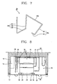
- Fig. 8 is a cross-sectional view illustrating a mechanical chamber of a refrigerator in accordance with an embodiment of the present invention
- Fig. 9 is a cross-sectional view taken along line IX-IX of Fig. 8 .
- a water tray 70 for storing water generated from a refrigeration cycle by defrosting is installed on the top surface of the mechanical chamber 16, a base plate 22 is mounted on the bottom surface of the mechanical chamber 16, and a compressor 24 for compressing refrigerants is mounted on the top surface of the base plate 22.
- the compressor 24 is connected to an outlet pipe 28 through a suction pipe 72, for sucking refrigerants from an evaporator, and also connected to an inlet pipe 26 through a discharge pipe 74, for discharging the compressed refrigerants to a condenser.
- the water tray 70 is formed in a rectangular box shape having its upper portion opened.
- the water tray 70 maintains an interval L2 from the ceiling surface of the mechanical chamber 16, for forming a space 76, and is mounted on the ceiling surface of the mechanical chamber 16 by brackets 78.
- the suction pipe 72 and the discharge pipe 74 pass through the space 76.
- a convex unit 80 is protruded in the up direction from the bottom surface of the water tray 70, for avoiding interferences with the compressor 24.
- the suction pipe 72 includes a first pipe unit 72a connected to one side of the compressor 24, a second pipe unit 72b connected to the first pipe unit 72a, for passing through the space 76 formed between the top surface of the water tray 70 and the ceiling surface of the mechanical chamber 16, a third pipe unit 72c curved in the down direction from the second pipe unit 72b and inclined to the rear portion of the mechanical chamber 16, a fourth pipe unit 72d curved in the horizontal direction from the third pipe unit 72c and disposed in the forward/backward direction of the mechanical chamber 16, and a fifth pipe unit 72e curved in the up direction from the fourth pipe unit 72d and connected to the outlet pipe 28.
- the first pipe unit 72a includes a horizontal unit 82 connected to one side of the compressor 24 and disposed in the horizontal direction, and an inclined unit 84 curved in the up direction from the horizontal unit 82 and inclined to the rear portion of the mechanical chamber 16.
- the discharge pipe 74 includes a first pipe unit 74a connected to one side of the compressor 24, a second pipe unit 74b curved from the first pipe unit 74a and disposed in the horizontal direction, for passing through the space 76 formed between the top surface of the water tray 70 and the ceiling surface of the mechanical chamber 16, a third pipe unit 74c curved in the down direction from both sides of the second pipe unit 74b, for passing through the water tray 70, and a fourth pipe unit 74d curved in a U shape from the third pipe unit 74c and connected to the inlet pipe 26.
- the first pipe unit 74a includes a horizontal unit 86 connected to one side of the compressor 24 and disposed in the horizontal direction, and an inclined unit 88 curved in the up direction from the horizontal unit 86 and inclined to the rear portion of the mechanical chamber 16.
- the third pipe unit 74c includes vertical units 90 curved in the down direction from both sides of the third pipe unit 74c, and a curved line unit 92 connected between the vertical units 90 and formed in a curved line shape along the bottom surface of the water tray 70.
- the suction pipe 72 and the discharge pipe 74 pass through the space 64 formed between the top surface of the water tray 70 and the ceiling surface of the mechanical chamber 16, and the portions of the suction pipe 72 and the discharge pipe 74 connected to the outlet pipe 28 and the inlet pipe 26 are formed in the U shape. Therefore, the suction pipe 72 and the discharge pipe 74 have the sufficient length to reduce or extinguish the vibration generated by the compressor 24.
- the suction pipe connected between the compressor and the outlet pipe of the evaporator and the discharge pipe connected between the compressor and the inlet pipe of the condenser are disposed to pass through the space formed between the water tray and the wall surface of the mechanical chamber, respectively, to obtain the sufficient length.
- the vibration generated by the compressor is almost extinguished through the suction pipe and the discharge pipe, and thus rarely transmitted to the refrigerant main body.
Landscapes
- Engineering & Computer Science (AREA)
- General Engineering & Computer Science (AREA)
- Physics & Mathematics (AREA)
- Mechanical Engineering (AREA)
- Thermal Sciences (AREA)
- Chemical & Material Sciences (AREA)
- Combustion & Propulsion (AREA)
- Public Health (AREA)
- Health & Medical Sciences (AREA)
- Epidemiology (AREA)
- Life Sciences & Earth Sciences (AREA)
- Hydrology & Water Resources (AREA)
- Water Supply & Treatment (AREA)
- Removal Of Water From Condensation And Defrosting (AREA)
- Devices That Are Associated With Refrigeration Equipment (AREA)
Claims (7)
- Schwingungsgedämpfter Kühlschrank, enthaltend:einen Kühlschrankhauptkörper (10) mit einer Kühlkammer zur Aufbewahrung von Lebensmitteln und einer mechanischen Kammer (16);einen in der mechanischen Kammer (16) angeordneten Kompressor (24) zur Komprimierung von Kühlmitteln; undeine Wasserschale (70) zur Unterbringung von Wasser, das beim Betrieb eines Kühlzyklus erzeugt wird, wobei die Wasserschale (70) in einem vorherbestimmten Abstand von der mechanischen Kammer (16) angeordnet ist, um zwischen der Wasserschale (70) und der mechanischen Kammer (16) einen Raum (76) zu bilden;ein Saugrohr (72), das an die Seite des Kompressors (24) angeschlossen ist, in der mechanischen Kammer (16) in der Breitenrichtung des Kühlschrankhauptkörpers (10) angeordnet ist, und an ein Auslassrohr (28) eines Verdampfers, der an einem Seitenende der mechanischen Kammer (16) angeordnet ist, angeschlossen ist; undein Ablassrohr (74), das zwischen der Seite des Kompressors (24) und einem Einlassrohr (26) eines Kondensators angeschlossen ist, um die Kühlmittel, die durch den Kompressor (24) komprimiert wurden, zu dem Kondensator abzugeben;dadurch gekennzeichnet, dass die Wasserschale (70) an der Deckenfläche der mechanischen Kammer (16) in einem Abstand von der Deckenfläche der mechanischen Kammer (16) eingerichtet ist, so dass der Raum (76) zwischen der oberen Fläche der Wasserschale (70) und der Deckenfläche der mechanischen Kammer (16) gebildet werden kann, und das Saugrohr (72) und das Ablassrohr (74) durch diesen Raum (76) verlaufen,wobei sowohl das Saugrohr (72) als auch das Ablassrohr (74) mehrere Male gekrümmt sind.
- Kühlschrank nach Anspruch 1, wobei das Saugrohr (72) Folgendes umfasst:eine erste Rohreinheit (72a), die an die Seite des Kompressors (24) angeschlossen ist;eine zweite Rohreinheit (72b), die an die erste Rohreinheit (72a) angeschlossen ist, um durch den Raum (76), der zwischen der Wasserschale (70) und der Wandfläche der mechanischen Kammer (16) gebildet ist, zu verlaufen; undeine dritte Rohreinheit (72c), die an die zweite Rohreinheit (72b) und das Auslassrohr (28) angeschlossen ist.
- Kühlschrank nach Anspruch 2, wobei die erste Rohreinheit (72a) Folgendes enthält:eine horizontale Einheit (82), die an die Seite des Kompressors (24) angeschlossen ist und in der horizontalen Richtung angeordnet ist; undeine schräge Einheit (84), die von der horizontalen Einheit (82) in einem Neigungswinkel in der Aufwärtsrichtung gebogen ist.
- Kühlschrank nach Anspruch 2, wobei die dritte Rohreinheit (72c) in einer U-Form ausgeführt ist, und zwar von der zweiten Rohreinheit (72b) in der Abwärtsrichtung gebogen ist und in der Aufwärtsrichtung gebogen ist, um an das Auslassrohr (28) angeschlossen zu werden.
- Kühlschrank nach Anspruch 1, wobei das Ablassrohr (74) Folgendes enthält:eine erste Rohreinheit (74a), die an die Seite des Kompressors (24) angeschlossen ist;eine zweite Rohreinheit (74b), die an die erste Rohreinheit (74a) angeschlossen ist, um durch den Raum (76), der zwischen der Wasserschale (70) und der Wandfläche der mechanischen Kammer (16) gebildet ist, zu verlaufen; undeine dritte Rohreinheit (74c), die an die zweite Rohreinheit (74b) und das Einlassrohr (26) angeschlossen ist.
- Kühlschrank nach Anspruch 5, wobei die erste Rohreinheit (74a) Folgendes enthält:eine horizontale Einheit (86), die an die Seite des Kompressors (24) angeschlossen ist und in der horizontalen Richtung angeordnet ist; undeine schräge Einheit (88), die von der horizontalen Einheit (86) in einem Neigungswinkel in der Aufwärtsrichtung gebogen ist.
- Kühlschrank nach Anspruch 5, wobei die dritte Rohreinheit (74c) in einer U-Form ausgeführt ist, und zwar von der zweiten Rohreinheit (74b) in der Abwärtsrichtung gebogen ist und in der Aufwärtsrichtung gebogen ist, um an das Einlassrohr (26) angeschlossen zu werden.
Applications Claiming Priority (2)
| Application Number | Priority Date | Filing Date | Title |
|---|---|---|---|
| KR2004035352 | 2004-05-18 | ||
| KR1020040035352A KR100575678B1 (ko) | 2004-05-18 | 2004-05-18 | 진동 저감형 냉장고 |
Publications (3)
| Publication Number | Publication Date |
|---|---|
| EP1598620A2 EP1598620A2 (de) | 2005-11-23 |
| EP1598620A3 EP1598620A3 (de) | 2006-01-04 |
| EP1598620B1 true EP1598620B1 (de) | 2012-02-01 |
Family
ID=34928003
Family Applications (1)
| Application Number | Title | Priority Date | Filing Date |
|---|---|---|---|
| EP04030807A Expired - Lifetime EP1598620B1 (de) | 2004-05-18 | 2004-12-27 | Kühlschrank mit Schwingungsdämpfung |
Country Status (5)
| Country | Link |
|---|---|
| US (1) | US7257961B2 (de) |
| EP (1) | EP1598620B1 (de) |
| JP (1) | JP2005331225A (de) |
| KR (1) | KR100575678B1 (de) |
| CN (1) | CN1322292C (de) |
Families Citing this family (13)
| Publication number | Priority date | Publication date | Assignee | Title |
|---|---|---|---|---|
| DE202006013707U1 (de) * | 2006-09-07 | 2006-12-14 | BSH Bosch und Siemens Hausgeräte GmbH | Kältegerät |
| KR20110019074A (ko) * | 2009-08-19 | 2011-02-25 | 엘지전자 주식회사 | 냉장고 |
| JP5624363B2 (ja) * | 2010-05-20 | 2014-11-12 | 株式会社東芝 | 冷蔵庫 |
| JP5624365B2 (ja) * | 2010-05-25 | 2014-11-12 | 株式会社東芝 | 冷蔵庫 |
| DE102011007414A1 (de) * | 2011-04-14 | 2012-10-18 | BSH Bosch und Siemens Hausgeräte GmbH | Verdunstungsvorrichtung für ein Kältegerät |
| JP2013100957A (ja) * | 2011-11-09 | 2013-05-23 | Sharp Corp | 冷蔵庫 |
| EP2795204B1 (de) * | 2011-12-23 | 2021-03-10 | GEA Bock GmbH | Verdichter |
| CN104296463B (zh) * | 2014-10-13 | 2016-08-24 | 合肥美的电冰箱有限公司 | 用于冰箱的接水盘和具有它的冰箱 |
| CN106123453A (zh) * | 2016-08-04 | 2016-11-16 | 海信(山东)冰箱有限公司 | 一种冰箱用蒸发皿组件及冰箱 |
| CN112556276A (zh) * | 2020-12-14 | 2021-03-26 | 海信(山东)冰箱有限公司 | 制冷系统及冷柜 |
| US12104585B2 (en) * | 2021-07-23 | 2024-10-01 | Nokia Shanghai Bell Co., Ltd. | Vibration isolation to protect electrical circuits from vibration-induced damage |
| CN113720073A (zh) * | 2021-09-25 | 2021-11-30 | 广东奥特龙电器制造有限公司 | 一种可自动循环加湿的酒柜 |
| CN117190566A (zh) * | 2023-09-11 | 2023-12-08 | 浙江星星冷链集成股份有限公司 | 一种静音冰箱 |
Citations (2)
| Publication number | Priority date | Publication date | Assignee | Title |
|---|---|---|---|---|
| US2721451A (en) * | 1952-06-24 | 1955-10-25 | Gen Electric | Drain pan |
| US5699677A (en) * | 1996-11-07 | 1997-12-23 | White Consolidated Industries, Inc. | Compressor mounted drain pan utilizing polyurethane adhesive |
Family Cites Families (14)
| Publication number | Priority date | Publication date | Assignee | Title |
|---|---|---|---|---|
| US2010546A (en) * | 1933-03-13 | 1935-08-06 | Gen Household Utilities Compan | Vibration eliminating means for refrigerating systems |
| US2185198A (en) * | 1936-10-06 | 1940-01-02 | Westinghouse Electric & Mfg Co | Air conditioning apparatus |
| US2661836A (en) * | 1952-08-01 | 1953-12-08 | O A Sutton Corp Inc | Air conditioning unit and apparatus for shipping |
| DE3911269A1 (de) * | 1989-04-07 | 1990-10-11 | Licentia Gmbh | Kompressor |
| JPH06147728A (ja) * | 1992-11-12 | 1994-05-27 | Matsushita Refrig Co Ltd | 冷蔵庫 |
| JPH09264658A (ja) * | 1996-03-29 | 1997-10-07 | Fujitsu General Ltd | 電気冷蔵庫 |
| KR19980062992A (ko) | 1996-12-30 | 1998-10-07 | 김영귀 | 자동차의 플라스틱 부품류 고정용 파스너 |
| KR20000027340A (ko) | 1998-10-28 | 2000-05-15 | 전주범 | 냉장고의 증발장치 |
| US6260373B1 (en) * | 2000-02-16 | 2001-07-17 | American Standard International Inc. | Heat exchanger with double vibration isolation |
| JP2002039665A (ja) * | 2000-07-28 | 2002-02-06 | Hoshizaki Electric Co Ltd | コンデンシングユニット引出し式冷却装置 |
| JP2002081851A (ja) * | 2000-09-06 | 2002-03-22 | Fujitsu General Ltd | 冷蔵庫機械室内の放熱パイプ取付用ホルダ |
| US6637230B2 (en) * | 2001-04-27 | 2003-10-28 | Denso Corporation | Automotive air-conditioner having sub-compressor driven by electric motor |
| US6904969B2 (en) * | 2001-10-15 | 2005-06-14 | Whirlpool Corporation | Time-bake cycle for a refrigerated oven |
| JP3946611B2 (ja) * | 2002-10-07 | 2007-07-18 | 株式会社東芝 | 冷蔵庫 |
-
2004
- 2004-05-18 KR KR1020040035352A patent/KR100575678B1/ko not_active Expired - Fee Related
- 2004-12-27 EP EP04030807A patent/EP1598620B1/de not_active Expired - Lifetime
-
2005
- 2005-01-03 US US11/025,907 patent/US7257961B2/en not_active Expired - Fee Related
- 2005-01-07 JP JP2005002325A patent/JP2005331225A/ja not_active Withdrawn
- 2005-02-21 CN CNB2005100095303A patent/CN1322292C/zh not_active Expired - Fee Related
Patent Citations (2)
| Publication number | Priority date | Publication date | Assignee | Title |
|---|---|---|---|---|
| US2721451A (en) * | 1952-06-24 | 1955-10-25 | Gen Electric | Drain pan |
| US5699677A (en) * | 1996-11-07 | 1997-12-23 | White Consolidated Industries, Inc. | Compressor mounted drain pan utilizing polyurethane adhesive |
Also Published As
| Publication number | Publication date |
|---|---|
| CN1699899A (zh) | 2005-11-23 |
| EP1598620A2 (de) | 2005-11-23 |
| US7257961B2 (en) | 2007-08-21 |
| KR20050110381A (ko) | 2005-11-23 |
| US20050257553A1 (en) | 2005-11-24 |
| JP2005331225A (ja) | 2005-12-02 |
| CN1322292C (zh) | 2007-06-20 |
| KR100575678B1 (ko) | 2006-05-03 |
| EP1598620A3 (de) | 2006-01-04 |
Similar Documents
| Publication | Publication Date | Title |
|---|---|---|
| EP1598620B1 (de) | Kühlschrank mit Schwingungsdämpfung | |
| CN102317714B (zh) | 冰箱的相关技术 | |
| EP2174083B1 (de) | Kühlvorrichtung | |
| US6519970B1 (en) | High-side refrigeration unit assembly | |
| US8931297B2 (en) | Cooling apparatus condenser, and a cooling apparatus including the same | |
| JP2007064597A (ja) | 冷蔵庫 | |
| KR101519136B1 (ko) | 냉장고 | |
| JP5884006B2 (ja) | 冷蔵庫 | |
| CN115200285B (zh) | 冰箱 | |
| WO2021227420A1 (zh) | 冰箱 | |
| KR20210058239A (ko) | 냉장고 | |
| KR100376833B1 (ko) | 김치저장고의 기계실 커버 체결부 구조 | |
| JP7436402B2 (ja) | 冷蔵庫 | |
| KR20210112183A (ko) | 냉장고 | |
| KR101657712B1 (ko) | 냉장고 | |
| KR200184603Y1 (ko) | 쇼케이스의 제상수 배수장치 | |
| JP7126041B2 (ja) | 取付部材、冷蔵庫 | |
| KR100651308B1 (ko) | 냉장고 | |
| KR100557439B1 (ko) | 냉장고 | |
| JP2000154965A (ja) | 冷蔵庫 | |
| KR20210058240A (ko) | 냉장고 | |
| WO2025232833A1 (zh) | 一种冰箱及其控制方法 | |
| JP2007064591A (ja) | 冷蔵庫 | |
| KR100661833B1 (ko) | 냉장고 | |
| KR20240078741A (ko) | 냉장고 |
Legal Events
| Date | Code | Title | Description |
|---|---|---|---|
| PUAI | Public reference made under article 153(3) epc to a published international application that has entered the european phase |
Free format text: ORIGINAL CODE: 0009012 |
|
| PUAL | Search report despatched |
Free format text: ORIGINAL CODE: 0009013 |
|
| AK | Designated contracting states |
Kind code of ref document: A2 Designated state(s): AT BE BG CH CY CZ DE DK EE ES FI FR GB GR HU IE IS IT LI LT LU MC NL PL PT RO SE SI SK TR |
|
| AX | Request for extension of the european patent |
Extension state: AL BA HR LV MK YU |
|
| AK | Designated contracting states |
Kind code of ref document: A3 Designated state(s): AT BE BG CH CY CZ DE DK EE ES FI FR GB GR HU IE IS IT LI LT LU MC NL PL PT RO SE SI SK TR |
|
| AX | Request for extension of the european patent |
Extension state: AL BA HR LV MK YU |
|
| 17P | Request for examination filed |
Effective date: 20060523 |
|
| AKX | Designation fees paid |
Designated state(s): DE FR GB IT NL |
|
| 17Q | First examination report despatched |
Effective date: 20070314 |
|
| GRAP | Despatch of communication of intention to grant a patent |
Free format text: ORIGINAL CODE: EPIDOSNIGR1 |
|
| GRAS | Grant fee paid |
Free format text: ORIGINAL CODE: EPIDOSNIGR3 |
|
| GRAA | (expected) grant |
Free format text: ORIGINAL CODE: 0009210 |
|
| AK | Designated contracting states |
Kind code of ref document: B1 Designated state(s): DE FR GB IT NL |
|
| REG | Reference to a national code |
Ref country code: GB Ref legal event code: FG4D |
|
| RAP2 | Party data changed (patent owner data changed or rights of a patent transferred) |
Owner name: LG ELECTRONICS INC. |
|
| REG | Reference to a national code |
Ref country code: DE Ref legal event code: R096 Ref document number: 602004036347 Country of ref document: DE Effective date: 20120329 |
|
| REG | Reference to a national code |
Ref country code: NL Ref legal event code: VDEP Effective date: 20120201 |
|
| PG25 | Lapsed in a contracting state [announced via postgrant information from national office to epo] |
Ref country code: NL Free format text: LAPSE BECAUSE OF FAILURE TO SUBMIT A TRANSLATION OF THE DESCRIPTION OR TO PAY THE FEE WITHIN THE PRESCRIBED TIME-LIMIT Effective date: 20120201 |
|
| PLBE | No opposition filed within time limit |
Free format text: ORIGINAL CODE: 0009261 |
|
| STAA | Information on the status of an ep patent application or granted ep patent |
Free format text: STATUS: NO OPPOSITION FILED WITHIN TIME LIMIT |
|
| 26N | No opposition filed |
Effective date: 20121105 |
|
| REG | Reference to a national code |
Ref country code: DE Ref legal event code: R097 Ref document number: 602004036347 Country of ref document: DE Effective date: 20121105 |
|
| REG | Reference to a national code |
Ref country code: FR Ref legal event code: PLFP Year of fee payment: 12 |
|
| REG | Reference to a national code |
Ref country code: FR Ref legal event code: PLFP Year of fee payment: 13 |
|
| PGFP | Annual fee paid to national office [announced via postgrant information from national office to epo] |
Ref country code: GB Payment date: 20161110 Year of fee payment: 13 Ref country code: DE Payment date: 20161107 Year of fee payment: 13 Ref country code: FR Payment date: 20161114 Year of fee payment: 13 |
|
| PGFP | Annual fee paid to national office [announced via postgrant information from national office to epo] |
Ref country code: IT Payment date: 20161215 Year of fee payment: 13 |
|
| REG | Reference to a national code |
Ref country code: DE Ref legal event code: R119 Ref document number: 602004036347 Country of ref document: DE |
|
| GBPC | Gb: european patent ceased through non-payment of renewal fee |
Effective date: 20171227 |
|
| REG | Reference to a national code |
Ref country code: FR Ref legal event code: ST Effective date: 20180831 |
|
| PG25 | Lapsed in a contracting state [announced via postgrant information from national office to epo] |
Ref country code: FR Free format text: LAPSE BECAUSE OF NON-PAYMENT OF DUE FEES Effective date: 20180102 Ref country code: DE Free format text: LAPSE BECAUSE OF NON-PAYMENT OF DUE FEES Effective date: 20180703 Ref country code: IT Free format text: LAPSE BECAUSE OF NON-PAYMENT OF DUE FEES Effective date: 20171227 |
|
| PG25 | Lapsed in a contracting state [announced via postgrant information from national office to epo] |
Ref country code: GB Free format text: LAPSE BECAUSE OF NON-PAYMENT OF DUE FEES Effective date: 20171227 |