EP1593308A2 - Vorrichtung zur Herstellung von Brotterrinen - Google Patents
Vorrichtung zur Herstellung von Brotterrinen Download PDFInfo
- Publication number
- EP1593308A2 EP1593308A2 EP05009700A EP05009700A EP1593308A2 EP 1593308 A2 EP1593308 A2 EP 1593308A2 EP 05009700 A EP05009700 A EP 05009700A EP 05009700 A EP05009700 A EP 05009700A EP 1593308 A2 EP1593308 A2 EP 1593308A2
- Authority
- EP
- European Patent Office
- Prior art keywords
- milling
- bread
- milling head
- cutting element
- loaves
- Prior art date
- Legal status (The legal status is an assumption and is not a legal conclusion. Google has not performed a legal analysis and makes no representation as to the accuracy of the status listed.)
- Withdrawn
Links
Images

Classifications
-
- A—HUMAN NECESSITIES
- A21—BAKING; EDIBLE DOUGHS
- A21C—MACHINES OR EQUIPMENT FOR MAKING OR PROCESSING DOUGHS; HANDLING BAKED ARTICLES MADE FROM DOUGH
- A21C15/00—Apparatus for handling baked articles
- A21C15/04—Cutting or slicing machines or devices specially adapted for baked articles other than bread
Definitions
- the invention relates to a device for the production of bread terrines.
- a device for the production of bread terrines are loaves, corresponding to the outer Form of the desired bread terrines are formed, first in each case in a cover piece and a lower part parts.
- Ansch manend is from the gate area from each one cavity introduced into the lower parts of the loaves.
- Such Device is known from DE 102 47 080 A1.
- the known device has a separating device with, for example a horizontally extending saw blade of a circular or bandsaw to Disconnect the lid from the lower part.
- a separating device with, for example a horizontally extending saw blade of a circular or bandsaw to Disconnect the lid from the lower part.
- This is the loaf on one Conveyor introduced to the saw blade, so that due to the conveying movement the saw blade passed through the loaf of bread and a lid is separated from the remaining lower part.
- the quality of the separating edge, which is generated in this separation process is therefore of two speeds dependent, namely the transport speed of the conveyor, on the one hand, and the speed of the saw blade, on the other.
- the synchronization requires a not insignificant mechanical or software-technical effort.
- the thus determined conveying speed the throughput of the entire Device because the same conveyor the loaves not only by the Separator transported through, but also the transport of Bread loaves through the entire device and all processing steps through accomplished.
- the known device mechanically produces a cavity in a loaf of bread. It must be ensured that on the one hand, the excavation large is enough to accommodate a desired amount of a court and, on the other hand, depending on the type of court, sufficient strong sidewalls remain, so after filling the Do not soak the bread dough container too fast and lick it.
- the too Milling diameter is therefore not only dependent on the diameter the loaf to be processed, which may vary in batches.
- Of the Diameter should also be selected according to the liquid content of the Dish that is to be served in the loaf, and how strong Accordingly, the side wall to be created Brotterrine be dimensioned got to. As a result, it must be possible to have a variety of different ones To produce diameters with the device. In the known Device is a tool change required.
- the known device to the effect to improve that the separating device easy to different Boundary conditions can be adjusted without the machining process to adversely affect the overall device.
- Another task is to improve the milling device insofar as the milling different cavities is simplified.
- the separating device of the device has a knife on, regardless of a possible conveying movement of the loaf is moved through it.
- the knife can be cheaper Have serrated edge. Instead of a knife can also be a saw blade or band are used.
- the invention thus deviates from the principle the known device from that the conveyor of the loaves through the device at the same time the relative movement between loaf of bread and knife or saw performs. Rather, it is based on the principle that the separating device regardless of the transport speed the conveyor an independent separation movement with its own speed performs. This offers the advantage of separating the lid from the bottom of a loaf of bread even if the conveyor stands still. This is the case in particular when the device is a has fixed milling device, which only when the conveyor is activated.
- the movement of the separating device can in principle be circular or rectilinear respectively.
- the Separating device about an axis perpendicular to a feed axis pivotable.
- the feed level corresponds to the transport surface of the conveyor, on which the loaves are fed to the separating device. Runs the supply in a horizontal plane, it is therefore the pivot axis of the separator vertically.
- the separating device thus describes a circular motion that in circular loaves of bread generally sufficient and constructively easy to accomplish is.
- the separating device displaceable parallel to the feeding plane of the loaves. So that can the separating device also rectangular loaves (so-called box breads) completely capture, which in a circular movement of the separating device may not be fully processed.
- the device should not only have loaves with different layout, but also those with different height can handle.
- a advantageous embodiment of the invention is therefore that the separating device is adjustable perpendicular to the feed plane. This adjustability is structurally particularly easy to implement in a separation device, which is pivotable about an axis, because the pivot axis at the same time defines the direction of displacement of the separating device.
- the known separating device has a saw blade or band, the as in conventional circular or band saws driven in one direction rotating becomes.
- Saws tear with their teeth starting from a first page Material from the workpiece, transport it to the other, the opposite second side, where the saw blade from the workpiece again, and thus create a continuously deepening gap in the Workpiece.
- the fineness of the joint edge depends among other things on the Fineness of the serration of the saw and the speed with which the Teeth tear the material out of the workpiece.
- Knives where no teeth remove the material, but there are due to stiction the material adheres to the cutting surface and therefore being carried away.
- Another advantageous embodiment of the invention therefore provides that the knife is driven oscillatingly. This allows fraying along the separating edge on the underside or the lid of the bread terrine largely avoid.
- a holder for the lid piece is arranged in the separating device is that the cover piece during the separation process against a change in position secures relative to the lower part. It prevents the lid piece breaks before completion of the separation process or from the lower part optionally with breaking out of parts of the side wall of the Bottom parts breaks off and thus is no longer available as a lid or an unsightly impression.
- the holder comprises a means for applying a pressure force perpendicular to the feed plane the lid piece exercises.
- the holder from a resilient sheet, which doses during the separation process press on the top of the loaf of bread.
- a guide device is arranged in the separating device, the separated lid piece next to the lower part on the conveyor placed.
- the guide ensures that the lid piece so is placed next to the lower part, which in further processing steps on the lower part, especially when introducing the cavity, not disturbs. This is an exact assignment without much technical effort ensured by cover piece and lower part, so that an appealing Optics of Brotterrine is guaranteed.
- the device for the production of bread terrines should also be suitable be to produce Brotterrinen with different inner diameter. Therefore Milling heads with different cutter diameters is available expensive. Because the milling head comes into contact with food and is therefore subject to special hygienic requirements. These require that the milling head is made either entirely of stainless steel, but it is harder to process than standard steel. Or the normal steel manufactured milling head has a special coating, whereby a additional elaborate processing step is required. The production the milling head is therefore very expensive. This problem can be solved solve that the milling device allows a variable milling diameter. The milling diameter is determined by the arrangement of Cutting elements on the milling head and the millable produced by them Diameter. Are the cutting elements adjustably arranged on the milling head, so can advantageously with the same milling head different Achieve diameter.
- the milling head comprises a cutting element which is arranged displaceably is.
- the cutting element is radial and in a rail guided, which passes through the axis of rotation of the milling head. This is it is possible to have a cavity with a diameter corresponding to the length of the cutting element when the cutting element is centered in the Rotary axis is arranged. If, on the other hand, it goes to the axis of rotation adjusted outside, so the milling head creates a cavity with a corresponding larger diameter, up to twice the length of the cutting element can reach. So this construction is a structurally simple and Therefore inexpensive possibility of a milling head for different Diameter dar.
- the milling head additionally at least one immovable Having cutting element, which is on the milling head substantially extends radially and from the axis of rotation of the milling head to the outside. It then defines a minimum diameter of the cavity while the displaceable cutting element (s) cover the area up to a maximum diameter cover.
- the arrangement of the displaceable and immovable Cutting elements arbitrary. You are essentially constructive boundaries set.
- An advantageous embodiment of the invention it is when the Milling head an immovable center cutting edge and a movable outer cutting edge has, with respect to the axis of rotation of the milling head to each other include an angle. By an arrangement at an angle to each other and not parallel to each other can be acting on the milling head Distribute forces evenly.
- the milling head of the present device is subject to wear.
- a Fräskopf loud is expensive for the reasons mentioned above.
- the milling head comprises a Cutting element holder into which a displaceable and / or an immovable Cutting element can be used and interchangeable. In order to does not have to wear the entire milling head, but only the Cutting elements are replaced, which is cheaper.
- the displaceable Cutting element adjustable to locking points. This facilitates in particular the repeated setting of a certain diameter and thus increases the user-friendliness.
- the sliding cutting element without disassembly of the milling head adjustable.
- the cutter diameter mechanically, in particular changeable during operation of the mill.
- this reduces the impairment of occupational safety at the device for the operator.
- it is with a while of milling variable cutter diameter with a fixed one Milling possible, for example, down the truncated cone rejuvenating or for the at least in Bavaria widespread "Löwenterrine" to create a typical bulbous inner shape in a loaf of bread.
- the means integrated in the conveyor for fixing the loaf of bread includes, that means depending on the location in the device automatically center and reopen.
- the centering can be done by annularly arranged holding pliers simultaneously and evenly move toward each other and towards a common center. This movement and opening the holding tongs find advantageous way automatically and in each case at the same position of the conveyor instead.
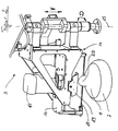
- FIG. 1 A view of an apparatus 1 for the production of bread terrines is shown in FIG 1.
- a conveyor 2 leads (not shown) loaves 6 a separating device 3 and a milling device 4 to that of hygienic and Safety reasons are encapsulated in a housing 5.
- the conveyor 2 passes through the housing 5 by flaps 9, which also pass allow loaves 6 on the conveyor 2.
- the work of the two Devices 3, 4 can by Acrylsichtrome 10 in the housing. 5 be monitored.
- the maintenance of the facilities 3, 4 is not over shown openings on the back of the housing 5.
- the housing. 5 covers the plate-shaped conveyor 2 only partially, so that in her exposed part of a new loaf of bread 6 applied and a processed be removed by the operator of the conveyor 2 can do without having to travel long distances.
- the devices 3, 4 in position supply has the conveyor 2 holding devices 11 with circularly arranged holding forceps 12.
- the holding forceps 12 have mandrels 13, with which they dig into the crust of the loaf 6 at the same time, to immovably hold the loaf 6 during processing to To prevent him from turning while milling.
- the holding forceps shown in an open position. Do you have the case 5 leave, open it automatically, allowing the operator of the holding device 11 remove a processed loaf of bread 6 and give her an unprocessed can use.
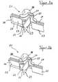
- a arranged in the housing 5 separating device 3 shows Figure 2.
- a the axis 15 performing component is fixedly connected to the device 1.
- the boom 14 additionally vertically in the directions of the Double arrow V movable.
- the boom 14 comprises a plate 16 which a motor 17 which oscillates a knife 18 in its longitudinal direction drives.
- a resilient plate 19 is seconded, which can deflect in the direction of the knife 18 away.
- the separating device 3 In operation of the device 1, the separating device 3 by means of the conveyor 2 a loaf of bread 6 supplied. While the conveyor 2 is stopped to mill a loaf of bread 6, comes a subsequent Loaf of bread 6 at the separating device to a stop. Now the separator pivots 3 about the axis 15 to the loaf of bread 6. She pulls the oscillating Knife 18 through the loaf of bread 6 to this in a lower part 7 and a Cover piece 8 to be cut. So that the lid piece 8 does not break in or before completion of the separation process breaks off from the lower part 7, presses the sheet 19 on the lid piece 8 and keeps it so in its position on the lower part. 7
- the separation device has adjustment options: around the separation device for loaves to divide 6 different heights, is the Outrigger along the axis 15 slidably formed. Should cover pieces 8 different heights can be made, so are the knife 18 and the resilient plate 19 relative to the plate 16 adjustably set up. Finally, both the speed of the knife 18 and Also, the pivoting speed of the boom 14 can be varied. A suitable speed for the oscillating movement of the blade 18 is about 1000 strokes / min at a feed rate of the knife 18 of about 10 cm / s.
- the resilient plate 19 represents the simplest embodiment of a holder for the lid piece 8, which has almost any lid shape effect. comes by contrast, only a certain shape of a cover piece 8 for processing, For example, as shown in Figure 2 with a cam 20, so is the holder advantageously adapt thereto. It can then exist in a roller, which has one of the cam 20 corresponding circumferential recess.
- a holder is suitable, in addition to at least a part of horizontal forces during the separation process by the oscillating Knife 18 act on the cover piece, record and so on Fracture of the cover piece 8 counteract.
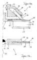
- a milling head 21 of the device 1 is shown in FIGS. 3a and 3b. He includes an immovable cutting element 22 and two movable Cutting elements 23. They each have a foot 24, which in a Rail 25 is held interchangeable with a cutting element holder 26. The rails 25 both of the non-displaceable cutting element 22 as well the displaceable cutting elements 23 extend radially and intersect Therefore, in the axis of rotation of the milling head 21. They are in a right Angle to each other. Each foot 24 of the cutting elements 22, 23 has latches 27, which engage in associated catches 28 in the rails 25 and fix the cutting elements 22, 23 stationary in the milling head 21.
- the Locks 27 consist in a simple embodiment of screws, which are screwed in a thread in the foot 24 and therefore not necessary Way in a corresponding thread in the rail 25, but there between Protrusions engage and so the cutting element 22, 23 immovable hold.
- the cutting elements 22, 23 carry floor cutting 29, the in a final state of the bread terrine produce their bottom, and wall cutting 30, which are at a right angle to the bottom edges 29.
- the immovable cutting element 22 is centered on the cutting element holder 26 arranged so that its axis of symmetry in the axis of rotation the milling head 21 is located. It is equipped with cutting edges 29, which correspond the direction of rotation of the milling head 21 are aligned.
- the cutting 29 can also be attached by a continuous roof profile Be formed. Then, the cutting element 22 at corresponding Dimensioning of his length and the foot 24 as a slidable Cutting element 23 are used, bringing a far-reaching Same parts concept is achieved.
- the cutting elements 22, 23 and in symmetrical construction of the Cutting element holder 26 of each cutting element 22, 23 at any Position used in the milling head 21, and so a one-sided wear the cutting edges 29 are counteracted.
- the sliding cutting elements 23 can be a minimum diameter in the size of the length of the non-displaceable cutting element 22 generate.
- the sliding cutting elements For example, it can be made from a slightly larger diameter at cutting elements 23 in a retracted position, as shown in FIG 3a, up to a maximum diameter of cutting elements 23rd in an extended position, as shown in Figure 3b, vary. In every both these and the intermediate positions are the Cutting elements 23 by means of the latches 24 in the notches 25 detectable.
- the cutting elements 22, 23 shown in FIGS. 3a and 3b have bottom cutting edges 29 and wall cutting 30 on each other at right angles are arranged. However, they can also be used in other ways, e.g. in one Angles with more than 90 ° to each other or with a rounding at the apex be provided with a different design of the milled Interior of the Brotterrine.
- FIG. 4 illustrates a principle of a milling head which can be adjusted during operation 31.
- the milling head 31 comprises a cutting element 32 with a bottom cutting edge 29, a wall cutting 30 and a foot 33, the extent with the cutting elements 22, 23 of Figures 3a and 3b is comparable.
- Deviating from the foot 33 is mounted slightly displaceable in the rail 34. This can be achieved by a special surface treatment of the contact surfaces the foot 33 and the rail 34 or by (not shown) Longitudinal storage to be ensured.
- a guide pin 34 at an angle of about 45 ° and runs in the plane the cutting element 32 in the direction of a rotation axis 35 of the milling head 31 out.
- the foot 33 is mounted in a rail 36, which is part of a Cutting element holder 37 of the milling head 31 is.
- the guide pin 34 protrudes into a guide member 38, which one according to the inclination of the guide pin 34 inclined channel 39, in which the guide pin 34 is mounted on longitudinal bearings 40.
- the guide element 38 is part the milling head 31 and parallel to the axis of rotation 35 in the Directions of the double arrow V arranged vertically displaceable.
- About one Control piece 41 can be the guide member 38 to move in the altitude.
- the inclination of the guide pin 34 and at least partially surrounding him Channels 39 serve to provide vertical movement of the guide element 38 in a direction of arrow V in a horizontal movement of Cutting elements 32 along the rail 36 implement.
- the inclinations of the guide pin 34 and the channel 38 are adapted and may vary depending on other constraints or smaller angle.
- the longitudinal bearing 40 exercises both a vertical and a horizontal force on the guide pin 34. This transmits the forces on the foot 33. He can not avoid the vertical force, but only the horizontal by movement in the longitudinal direction of the rail 36. In a downward movement of the guide member 38 he does so by he moves in the direction of the axis of rotation.
- the guide element 38 rotates with the cutting element holder 37 with, otherwise in addition to the sliding movement of the guide pin 34 in the channel 39 another relative movement in the direction of rotation would occur that would be stored accordingly.
- the storage of the rotary motion the guide element 38 takes place on the control piece 41 and must have tensile and compressive forces in the directions of the double arrow Record V.
- the control piece for example, on a stored parallel to the direction of rotation of the guide member 38 extending ring be on the then adjusting forces for changing the radius of the milling head 31 act.
- the basic arrangement shown in Figure 4 allows adjustment the cutting radius of the milling head 31 during operation of a milling device.
- the guide member 38 is arranged so that in each Position of the cutting element 32, so even at a minimum diameter, the wall cutting edge 30 describes the largest circumference of the milling head 31.
- This arrangement thus allows - with appropriate design of the Cutting elements - a variation of the inside diameter of a bread terrine, so that, for example, a bulbous to the broad bottom of the tureen wide interior shape can be produced, comparable to a "lion trough", usually served in Bavaria soups.
Landscapes
- Life Sciences & Earth Sciences (AREA)
- Engineering & Computer Science (AREA)
- Food Science & Technology (AREA)
- Manufacturing And Processing Devices For Dough (AREA)
Abstract
Description
- Figur 1
- eine Gesamtansicht einer Vorrichtung zur Herstellung von Brotterrinen,
- Figur 2
- eine Teilansicht einer Abtrenneinrichtung ,
- Figur 3a
- eine Ansicht eines Fräskopfes mit zusammen geschobenen verschieblichen Schneidelementen,
- Figur 3b
- eine Ansicht des Fräskopfes mit auseinander geschobenen verschieblichen Schneidelementen,
- Figur 4a
- einen Teilschnitt eines verstellbaren Fräskopfs und
- Figur 4b
- eine Teildraufsicht auf einen verstellbaren Fräskopf.
- 1
- Vorrichtung
- 2
- Fördereinrichtung
- 3
- Abtrenneinrichtung
- 4
- Fräseinrichtung
- 5
- Gehäuse
- 6
- Brotlaib
- 7
- Unterteil
- 8
- Deckelstück
- 9
- Klappe
- 10
- Acrylfenster
- 11
- Halteeinrichtung
- 12
- Haltezange
- 13
- Dorn
- 14
- Ausleger
- 15
- Achse
- 16
- Platte
- 17
- Motor
- 18
- Messer
- 19
- federndes Blech
- 20
- Nocke
- 21
- Fräskopf
- 22
- unverschiebliches Schneidelement
- 23
- verschiebliches Schneidelement
- 24
- Fuß
- 25
- Schiene
- 26
- Schneidelementenhalter
- 27
- Verriegelung
- 28
- Raste
- 29
- Bodenschneide
- 30
- Wandschneide
- 31
- Verstellbarer Fräskopf
- 32
- Schneidelement
- 33
- Fuß
- 34
- Führungszapfen
- 35
- Drehachse
- 36
- Schiene
- 37
- Schneidelementhalter
- 38
- Führungselement
- 39
- Kanal
- 40
- Längslager
- 41
- Steuerstück
Claims (18)
- Vorrichtung (1) zur Herstellung von Brotterrinen (10) aus Brotlaiben (6), mit einer Abtrenneinrichtung, mit der ein Deckelstück (8) eines Brotlaibs (6) von einem Unterteil (7) abtrennbar ist, und mit einer Fräseinrichtung (2), mit der von einer Abtrennfläche aus in das Unterteil (7) eine Kavität (9) einfräsbar ist, dadurch gekennzeichnet, dass die Abtrenneinrichtung ein Messer aufweist, das unabhängig von einer möglichen Förderbewegung des Brotlaibs (6) durch ihn hindurch bewegbar ausgebildet ist.
- Vorrichtung nach Anspruch 1, dadurch gekennzeichnet, dass die Abtrenneinrichtung um eine auf eine Zuführebene lotrechte Achse schwenkbar ist.
- Vorrichtung nach Anspruch 1, dadurch gekennzeichnet, dass die Abtrenneinrichtung parallel zur Zuführebene der Brotlaibe (6) zur Abtrenneinrichtung verschiebbar ist.
- Vorrichtung nach einem der obigen Ansprüche, dadurch gekennzeichnet, dass die Abtrenneinrichtung lotrecht zur Zuführebene verstellbar ist.
- Vorrichtung nach einem der obigen Ansprüche, dadurch gekennzeichnet, dass das Messer oszillierend angetrieben ist.
- Vorrichtung (1) zur Herstellung von Brotterrinen (10) aus Brotlaiben (6), insbesondere nach einem der obigen Ansprüche, dadurch gekennzeichnet, dass in der Abtrenneinrichtung eine Halterung für das Deckelstück (8) angeordnet ist, die das Deckelstück (8) während des Abtrennvorgangs gegen eine Lageänderung relativ zum Unterteil (7) sichert.
- Vorrichtung nach Anspruch 6, dadurch gekennzeichnet, dass die Halterung ein Mittel umfasst, das eine auf die Zuführebene lotrecht gerichtete Druckkraft auf das Deckelstück (8) ausübt.
- Vorrichtung (1) zur Herstellung von Brotterrinen (10) aus Brotlaiben (6), insbesondere nach einem der obigen Ansprüche, dadurch gekennzeichnet, dass eine Leitvorrichtung angeordnet ist, die das abgetrennte Deckelstück (8) neben den Unterteil (7) auf der Fördereinrichtung platziert.
- Vorrichtung (1) zur Herstellung von Brotterrinen (10) aus Brotlaiben (6), mit einer Fräseinrichtung (2), mit der in ein Unterteil (7) des Brotlaibs (6) von einer Abtrennfläche aus eine Kavität (9) einfräsbar ist, dadurch gekennzeichnet, dass die Fräseinrichtung (2) einen variablen Fräsendurchmesser aufweist.
- Vorrichtung nach Anspruch 9, dadurch gekennzeichnet, dass die Fräseinrichtung (2) einen Fräskopf mit einem Schneidelement umfasst, das vorzugsweise radial verschieblich angeordnet ist.
- Vorrichtung nach Anspruch 9, dadurch gekennzeichnet, dass der Fräskopf zusätzlich ein unverschiebliches Schneidelement aufweist, das sich auf dem Fräskopf im Wesentlichen radial und von Drehachse des Fräskopfes nach außen hin erstreckt.
- Vorrichtung nach Anspruch einem der Ansprüche 9 oder 10, dadurch gekennzeichnet, dass der Fräskopf ein unverschiebliches Mittelschneidelement und ein verschiebliches Außenschneidelement aufweist, die bezüglich der Drehachse des Fräskopfes zueinander einen Winkel einschließen.
- Vorrichtung nach einem der Ansprüche 9 bis 12, dadurch gekennzeichnet, dass der Fräskopf einen Schneidenhalter umfasst, in den eine unverschiebliche und/oder ein verschiebliches Schneidelement einsetzbar und auswechselbar ist.
- Vorrichtung nach einem der Ansprüche 9 bis 13, dadurch gekennzeichnet, dass das verschiebliche Schneidelement auf Rastpunkten verstellbar ist.
- Vorrichtung nach einem der Ansprüche 10 bis 14, dadurch gekennzeichnet, dass das verschiebliche Schneidelement ohne Demontage des Fräskopfes verstellbar ist.
- Vorrichtung (1) nach Anspruch 10, 11 oder 15, dadurch gekennzeichnet, dass der Fräsendurchmesser maschinell, insbesondere während des Betriebs der Fräse, veränderbar ist.
- Vorrichtung (1) zur Herstellung von Brotterrinen (10) aus Brotlaiben (6), mit einer Abtrenneinrichtung nach einem der Ansprüche 1 bis 7 und/oder einer Leitvorrichtung nach Anspruch 8 und einer Fräseinrichtung nach einem der Ansprüche 9 bis 16.
- Vorrichtung (1) zur Herstellung von Brotterrinen (10) aus Brotlaiben (6), insbesondere nach einem der obigen Ansprüche, mit einer Fördereinrichtung, die in die Fördereinrichtung integrierte Mittel zum Fixieren des Brotlaibs (6) aufweist, dadurch gekennzeichnet, dass die Mittel in Abhängigkeit vom Ort in der Vorrichtung selbsttätig zentrieren und wieder öffnen.
Applications Claiming Priority (2)
| Application Number | Priority Date | Filing Date | Title |
|---|---|---|---|
| DE102004023035 | 2004-05-06 | ||
| DE200410023035 DE102004023035A1 (de) | 2004-05-06 | 2004-05-06 | Vorrichtung zur Herstellung von Brotterrinen |
Publications (2)
| Publication Number | Publication Date |
|---|---|
| EP1593308A2 true EP1593308A2 (de) | 2005-11-09 |
| EP1593308A3 EP1593308A3 (de) | 2008-08-27 |
Family
ID=34936092
Family Applications (1)
| Application Number | Title | Priority Date | Filing Date |
|---|---|---|---|
| EP05009700A Withdrawn EP1593308A3 (de) | 2004-05-06 | 2005-05-03 | Vorrichtung zur Herstellung von Brotterrinen |
Country Status (2)
| Country | Link |
|---|---|
| EP (1) | EP1593308A3 (de) |
| DE (1) | DE102004023035A1 (de) |
Cited By (1)
| Publication number | Priority date | Publication date | Assignee | Title |
|---|---|---|---|---|
| CN108260624A (zh) * | 2018-03-07 | 2018-07-10 | 王琳 | 一种便于更换刀具的糕点切片机 |
Family Cites Families (9)
| Publication number | Priority date | Publication date | Assignee | Title |
|---|---|---|---|---|
| US3059680A (en) * | 1960-02-01 | 1962-10-23 | Louis C Ridean | Bun boring machine |
| US3763765A (en) * | 1969-01-10 | 1973-10-09 | R Nelson | Apparatus and method for making filled food item |
| DE3629819A1 (de) * | 1985-10-02 | 1987-04-02 | Herlitzius Gmbh & Co Kg Geb | Maschine zum schneiden von im wesentlichen ringform aufweisenden backwaren |
| DE29614393U1 (de) * | 1996-08-20 | 1996-11-07 | Krumbein, Wolfgang, 99891 Tabarz | Vorrichtung zum Schneiden von Brötchen, insbesondere Hamburger-Brötchen |
| ES2158749B1 (es) * | 1998-05-28 | 2002-03-16 | Equipos Para Manutencion Y Obr | Maquina para la preparacion de productos alimenticios en lonchas superpuestas. |
| US6042864A (en) * | 1998-06-19 | 2000-03-28 | United Bakery Equipment Co. | Method and apparatus for cutting bread bowl bakery products |
| ES2218733T3 (es) * | 1998-06-29 | 2004-11-16 | Soremartec S.A. | Aparato para cortar conchas de cubierta formadas en una lamina de barquillo. |
| DE10019920A1 (de) * | 2000-04-20 | 2001-10-31 | Kai Volko Steinmetz | Kuchenschneidemaschine |
| DE10247080B4 (de) * | 2002-10-09 | 2007-02-15 | Anton Imielski | Vorrichtung und Verfahren zur Herstellung von Brotteiggefäßen |
-
2004
- 2004-05-06 DE DE200410023035 patent/DE102004023035A1/de not_active Withdrawn
-
2005
- 2005-05-03 EP EP05009700A patent/EP1593308A3/de not_active Withdrawn
Cited By (2)
| Publication number | Priority date | Publication date | Assignee | Title |
|---|---|---|---|---|
| CN108260624A (zh) * | 2018-03-07 | 2018-07-10 | 王琳 | 一种便于更换刀具的糕点切片机 |
| CN108260624B (zh) * | 2018-03-07 | 2020-07-14 | 安徽品滋味食品有限公司 | 一种便于更换刀具的糕点切片机 |
Also Published As
| Publication number | Publication date |
|---|---|
| EP1593308A3 (de) | 2008-08-27 |
| DE102004023035A1 (de) | 2005-11-24 |
Similar Documents
| Publication | Publication Date | Title |
|---|---|---|
| EP2329930B1 (de) | Vorrichtung zum Aufschneiden von Lebensmittelprodukten | |
| EP2532493A1 (de) | Portioniermaschine | |
| DE3145912A1 (de) | Kontinuierlich arbeitende schneidevorrichtung zur herstellung von abschnitten mit abgerundeten schnittkanten, deren kruemmungen entgegengesetzt verlaufen | |
| DE4236347C2 (de) | Längsschneideinrichtung | |
| DE3416664C2 (de) | Einrichtung zum Steuern der Schneidgeschwindigkeit des Sägeblattes einer Bandsägemaschine | |
| EP3412417B1 (de) | Schneidvorrichtung sowie schneidverfahren | |
| EP2374584B1 (de) | Vorrichtung zum Aufschneiden von Lebensmittelprodukten | |
| DE102013224311B3 (de) | Vorrichtung zum Bearbeiten von Werkstücken | |
| DE102010008047A1 (de) | Vorrichtung zum Aufschneiden von Lebensmittelprodukten | |
| DE1810052C3 (de) | Vorrichtung zum Durchschneiden von kontinuierlich zugeführten Rohren | |
| DE2820539A1 (de) | Verfahren zum durchtrennen von beschichtetem plattenmaterial sowie einrichtung zu seiner durchfuehrung | |
| DE2461620A1 (de) | Vorrichtung zum erzeugen von ritzlinien in flachem papiermaterial | |
| EP1593308A2 (de) | Vorrichtung zur Herstellung von Brotterrinen | |
| EP1358976B1 (de) | Vorrichtung zum Herauslösen von Teilbereichen aus einem bahnartigen Folienmaterial | |
| DE102010019744A1 (de) | Vorrichtung zum Aufschneiden von Lebensmittelprodukten | |
| EP0744255A2 (de) | Vorrichtung zum Zerlegen von Baumstämmen in Holzerzeugnisse und Fräskopf für eine solche Vorrichtung | |
| DE3626964A1 (de) | Kreisschere | |
| DE102010011172A1 (de) | Vorrichtung zum Aufschneiden von Lebensmittelprodukten | |
| DE19735237A1 (de) | Beschneidwerkzeug | |
| DE2632425C3 (de) | Maschine zum öffnen von Briefumschlägen | |
| DE3721031C2 (de) | ||
| DE69411608T2 (de) | Verfahren und Vorrichtung zum Abrunden von Ecken flacher Zuschnitte | |
| EP0896847B1 (de) | Zerkleinerungsvorrichtung für eine Beschneidevorrichtung | |
| DE1604667C (de) | Verfahren und Vorrichtung zum Ent graten von aus thermoplastischem Kunst stoff hergestellten Flaschen od dgl Hohlkörpern | |
| DE2942001A1 (de) | Maschine zum herstellen von schrauben o.dgl. |
Legal Events
| Date | Code | Title | Description |
|---|---|---|---|
| PUAI | Public reference made under article 153(3) epc to a published international application that has entered the european phase |
Free format text: ORIGINAL CODE: 0009012 |
|
| AK | Designated contracting states |
Kind code of ref document: A2 Designated state(s): AT BE BG CH CY CZ DE DK EE ES FI FR GB GR HU IE IS IT LI LT LU MC NL PL PT RO SE SI SK TR |
|
| AX | Request for extension of the european patent |
Extension state: AL BA HR LV MK YU |
|
| PUAL | Search report despatched |
Free format text: ORIGINAL CODE: 0009013 |
|
| AK | Designated contracting states |
Kind code of ref document: A3 Designated state(s): AT BE BG CH CY CZ DE DK EE ES FI FR GB GR HU IE IS IT LI LT LU MC NL PL PT RO SE SI SK TR |
|
| AX | Request for extension of the european patent |
Extension state: AL BA HR LV MK YU |
|
| AKX | Designation fees paid | ||
| STAA | Information on the status of an ep patent application or granted ep patent |
Free format text: STATUS: THE APPLICATION IS DEEMED TO BE WITHDRAWN |
|
| 18D | Application deemed to be withdrawn |
Effective date: 20080828 |
|
| REG | Reference to a national code |
Ref country code: DE Ref legal event code: 8566 |