EP1589301B1 - Système à cycle d'éjection avec pression critique du fluide frigorigène - Google Patents
Système à cycle d'éjection avec pression critique du fluide frigorigène Download PDFInfo
- Publication number
- EP1589301B1 EP1589301B1 EP05016204.9A EP05016204A EP1589301B1 EP 1589301 B1 EP1589301 B1 EP 1589301B1 EP 05016204 A EP05016204 A EP 05016204A EP 1589301 B1 EP1589301 B1 EP 1589301B1
- Authority
- EP
- European Patent Office
- Prior art keywords
- refrigerant
- ejector
- pressure
- evaporator
- gas
- Prior art date
- Legal status (The legal status is an assumption and is not a legal conclusion. Google has not performed a legal analysis and makes no representation as to the accuracy of the status listed.)
- Expired - Lifetime
Links
Images


Classifications
-
- F—MECHANICAL ENGINEERING; LIGHTING; HEATING; WEAPONS; BLASTING
- F25—REFRIGERATION OR COOLING; COMBINED HEATING AND REFRIGERATION SYSTEMS; HEAT PUMP SYSTEMS; MANUFACTURE OR STORAGE OF ICE; LIQUEFACTION SOLIDIFICATION OF GASES
- F25B—REFRIGERATION MACHINES, PLANTS OR SYSTEMS; COMBINED HEATING AND REFRIGERATION SYSTEMS; HEAT PUMP SYSTEMS
- F25B41/00—Fluid-circulation arrangements
-
- F—MECHANICAL ENGINEERING; LIGHTING; HEATING; WEAPONS; BLASTING
- F25—REFRIGERATION OR COOLING; COMBINED HEATING AND REFRIGERATION SYSTEMS; HEAT PUMP SYSTEMS; MANUFACTURE OR STORAGE OF ICE; LIQUEFACTION SOLIDIFICATION OF GASES
- F25B—REFRIGERATION MACHINES, PLANTS OR SYSTEMS; COMBINED HEATING AND REFRIGERATION SYSTEMS; HEAT PUMP SYSTEMS
- F25B29/00—Combined heating and refrigeration systems, e.g. operating alternately or simultaneously
- F25B29/003—Combined heating and refrigeration systems, e.g. operating alternately or simultaneously of the compression type system
-
- F—MECHANICAL ENGINEERING; LIGHTING; HEATING; WEAPONS; BLASTING
- F25—REFRIGERATION OR COOLING; COMBINED HEATING AND REFRIGERATION SYSTEMS; HEAT PUMP SYSTEMS; MANUFACTURE OR STORAGE OF ICE; LIQUEFACTION SOLIDIFICATION OF GASES
- F25B—REFRIGERATION MACHINES, PLANTS OR SYSTEMS; COMBINED HEATING AND REFRIGERATION SYSTEMS; HEAT PUMP SYSTEMS
- F25B9/00—Compression machines, plants or systems, in which the refrigerant is air or other gas of low boiling point
- F25B9/002—Compression machines, plants or systems, in which the refrigerant is air or other gas of low boiling point characterised by the refrigerant
- F25B9/008—Compression machines, plants or systems, in which the refrigerant is air or other gas of low boiling point characterised by the refrigerant the refrigerant being carbon dioxide
-
- B—PERFORMING OPERATIONS; TRANSPORTING
- B60—VEHICLES IN GENERAL
- B60H—ARRANGEMENTS OF HEATING, COOLING, VENTILATING OR OTHER AIR-TREATING DEVICES SPECIALLY ADAPTED FOR PASSENGER OR GOODS SPACES OF VEHICLES
- B60H1/00—Heating, cooling or ventilating [HVAC] devices
- B60H1/32—Cooling devices
- B60H2001/3286—Constructional features
- B60H2001/3298—Ejector-type refrigerant circuits
-
- F—MECHANICAL ENGINEERING; LIGHTING; HEATING; WEAPONS; BLASTING
- F25—REFRIGERATION OR COOLING; COMBINED HEATING AND REFRIGERATION SYSTEMS; HEAT PUMP SYSTEMS; MANUFACTURE OR STORAGE OF ICE; LIQUEFACTION SOLIDIFICATION OF GASES
- F25B—REFRIGERATION MACHINES, PLANTS OR SYSTEMS; COMBINED HEATING AND REFRIGERATION SYSTEMS; HEAT PUMP SYSTEMS
- F25B2309/00—Gas cycle refrigeration machines
- F25B2309/06—Compression machines, plants or systems characterised by the refrigerant being carbon dioxide
- F25B2309/061—Compression machines, plants or systems characterised by the refrigerant being carbon dioxide with cycle highest pressure above the supercritical pressure
-
- F—MECHANICAL ENGINEERING; LIGHTING; HEATING; WEAPONS; BLASTING
- F25—REFRIGERATION OR COOLING; COMBINED HEATING AND REFRIGERATION SYSTEMS; HEAT PUMP SYSTEMS; MANUFACTURE OR STORAGE OF ICE; LIQUEFACTION SOLIDIFICATION OF GASES
- F25B—REFRIGERATION MACHINES, PLANTS OR SYSTEMS; COMBINED HEATING AND REFRIGERATION SYSTEMS; HEAT PUMP SYSTEMS
- F25B2339/00—Details of evaporators; Details of condensers
- F25B2339/04—Details of condensers
- F25B2339/047—Water-cooled condensers
-
- F—MECHANICAL ENGINEERING; LIGHTING; HEATING; WEAPONS; BLASTING
- F25—REFRIGERATION OR COOLING; COMBINED HEATING AND REFRIGERATION SYSTEMS; HEAT PUMP SYSTEMS; MANUFACTURE OR STORAGE OF ICE; LIQUEFACTION SOLIDIFICATION OF GASES
- F25B—REFRIGERATION MACHINES, PLANTS OR SYSTEMS; COMBINED HEATING AND REFRIGERATION SYSTEMS; HEAT PUMP SYSTEMS
- F25B2341/00—Details of ejectors not being used as compression device; Details of flow restrictors or expansion valves
- F25B2341/001—Ejectors not being used as compression device
- F25B2341/0011—Ejectors with the cooled primary flow at reduced or low pressure
-
- F—MECHANICAL ENGINEERING; LIGHTING; HEATING; WEAPONS; BLASTING
- F25—REFRIGERATION OR COOLING; COMBINED HEATING AND REFRIGERATION SYSTEMS; HEAT PUMP SYSTEMS; MANUFACTURE OR STORAGE OF ICE; LIQUEFACTION SOLIDIFICATION OF GASES
- F25B—REFRIGERATION MACHINES, PLANTS OR SYSTEMS; COMBINED HEATING AND REFRIGERATION SYSTEMS; HEAT PUMP SYSTEMS
- F25B2341/00—Details of ejectors not being used as compression device; Details of flow restrictors or expansion valves
- F25B2341/001—Ejectors not being used as compression device
- F25B2341/0012—Ejectors with the cooled primary flow at high pressure
-
- F—MECHANICAL ENGINEERING; LIGHTING; HEATING; WEAPONS; BLASTING
- F25—REFRIGERATION OR COOLING; COMBINED HEATING AND REFRIGERATION SYSTEMS; HEAT PUMP SYSTEMS; MANUFACTURE OR STORAGE OF ICE; LIQUEFACTION SOLIDIFICATION OF GASES
- F25B—REFRIGERATION MACHINES, PLANTS OR SYSTEMS; COMBINED HEATING AND REFRIGERATION SYSTEMS; HEAT PUMP SYSTEMS
- F25B2341/00—Details of ejectors not being used as compression device; Details of flow restrictors or expansion valves
- F25B2341/001—Ejectors not being used as compression device
- F25B2341/0013—Ejector control arrangements
-
- F—MECHANICAL ENGINEERING; LIGHTING; HEATING; WEAPONS; BLASTING
- F25—REFRIGERATION OR COOLING; COMBINED HEATING AND REFRIGERATION SYSTEMS; HEAT PUMP SYSTEMS; MANUFACTURE OR STORAGE OF ICE; LIQUEFACTION SOLIDIFICATION OF GASES
- F25B—REFRIGERATION MACHINES, PLANTS OR SYSTEMS; COMBINED HEATING AND REFRIGERATION SYSTEMS; HEAT PUMP SYSTEMS
- F25B2341/00—Details of ejectors not being used as compression device; Details of flow restrictors or expansion valves
- F25B2341/06—Details of flow restrictors or expansion valves
- F25B2341/063—Feed forward expansion valves
-
- F—MECHANICAL ENGINEERING; LIGHTING; HEATING; WEAPONS; BLASTING
- F25—REFRIGERATION OR COOLING; COMBINED HEATING AND REFRIGERATION SYSTEMS; HEAT PUMP SYSTEMS; MANUFACTURE OR STORAGE OF ICE; LIQUEFACTION SOLIDIFICATION OF GASES
- F25B—REFRIGERATION MACHINES, PLANTS OR SYSTEMS; COMBINED HEATING AND REFRIGERATION SYSTEMS; HEAT PUMP SYSTEMS
- F25B2400/00—General features or devices for refrigeration machines, plants or systems, combined heating and refrigeration systems or heat-pump systems, i.e. not limited to a particular subgroup of F25B
- F25B2400/23—Separators
-
- F—MECHANICAL ENGINEERING; LIGHTING; HEATING; WEAPONS; BLASTING
- F25—REFRIGERATION OR COOLING; COMBINED HEATING AND REFRIGERATION SYSTEMS; HEAT PUMP SYSTEMS; MANUFACTURE OR STORAGE OF ICE; LIQUEFACTION SOLIDIFICATION OF GASES
- F25B—REFRIGERATION MACHINES, PLANTS OR SYSTEMS; COMBINED HEATING AND REFRIGERATION SYSTEMS; HEAT PUMP SYSTEMS
- F25B2500/00—Problems to be solved
- F25B2500/01—Geometry problems, e.g. for reducing size
-
- F—MECHANICAL ENGINEERING; LIGHTING; HEATING; WEAPONS; BLASTING
- F25—REFRIGERATION OR COOLING; COMBINED HEATING AND REFRIGERATION SYSTEMS; HEAT PUMP SYSTEMS; MANUFACTURE OR STORAGE OF ICE; LIQUEFACTION SOLIDIFICATION OF GASES
- F25B—REFRIGERATION MACHINES, PLANTS OR SYSTEMS; COMBINED HEATING AND REFRIGERATION SYSTEMS; HEAT PUMP SYSTEMS
- F25B2500/00—Problems to be solved
- F25B2500/18—Optimization, e.g. high integration of refrigeration components
-
- F—MECHANICAL ENGINEERING; LIGHTING; HEATING; WEAPONS; BLASTING
- F25—REFRIGERATION OR COOLING; COMBINED HEATING AND REFRIGERATION SYSTEMS; HEAT PUMP SYSTEMS; MANUFACTURE OR STORAGE OF ICE; LIQUEFACTION SOLIDIFICATION OF GASES
- F25B—REFRIGERATION MACHINES, PLANTS OR SYSTEMS; COMBINED HEATING AND REFRIGERATION SYSTEMS; HEAT PUMP SYSTEMS
- F25B2600/00—Control issues
- F25B2600/02—Compressor control
- F25B2600/025—Compressor control by controlling speed
- F25B2600/0253—Compressor control by controlling speed with variable speed
-
- F—MECHANICAL ENGINEERING; LIGHTING; HEATING; WEAPONS; BLASTING
- F25—REFRIGERATION OR COOLING; COMBINED HEATING AND REFRIGERATION SYSTEMS; HEAT PUMP SYSTEMS; MANUFACTURE OR STORAGE OF ICE; LIQUEFACTION SOLIDIFICATION OF GASES
- F25B—REFRIGERATION MACHINES, PLANTS OR SYSTEMS; COMBINED HEATING AND REFRIGERATION SYSTEMS; HEAT PUMP SYSTEMS
- F25B2600/00—Control issues
- F25B2600/17—Control issues by controlling the pressure of the condenser
-
- F—MECHANICAL ENGINEERING; LIGHTING; HEATING; WEAPONS; BLASTING
- F25—REFRIGERATION OR COOLING; COMBINED HEATING AND REFRIGERATION SYSTEMS; HEAT PUMP SYSTEMS; MANUFACTURE OR STORAGE OF ICE; LIQUEFACTION SOLIDIFICATION OF GASES
- F25B—REFRIGERATION MACHINES, PLANTS OR SYSTEMS; COMBINED HEATING AND REFRIGERATION SYSTEMS; HEAT PUMP SYSTEMS
- F25B2700/00—Sensing or detecting of parameters; Sensors therefor
- F25B2700/21—Temperatures
- F25B2700/2117—Temperatures of an evaporator
- F25B2700/21174—Temperatures of an evaporator of the refrigerant at the inlet of the evaporator
-
- F—MECHANICAL ENGINEERING; LIGHTING; HEATING; WEAPONS; BLASTING
- F25—REFRIGERATION OR COOLING; COMBINED HEATING AND REFRIGERATION SYSTEMS; HEAT PUMP SYSTEMS; MANUFACTURE OR STORAGE OF ICE; LIQUEFACTION SOLIDIFICATION OF GASES
- F25B—REFRIGERATION MACHINES, PLANTS OR SYSTEMS; COMBINED HEATING AND REFRIGERATION SYSTEMS; HEAT PUMP SYSTEMS
- F25B2700/00—Sensing or detecting of parameters; Sensors therefor
- F25B2700/21—Temperatures
- F25B2700/2117—Temperatures of an evaporator
- F25B2700/21175—Temperatures of an evaporator of the refrigerant at the outlet of the evaporator
-
- F—MECHANICAL ENGINEERING; LIGHTING; HEATING; WEAPONS; BLASTING
- F25—REFRIGERATION OR COOLING; COMBINED HEATING AND REFRIGERATION SYSTEMS; HEAT PUMP SYSTEMS; MANUFACTURE OR STORAGE OF ICE; LIQUEFACTION SOLIDIFICATION OF GASES
- F25B—REFRIGERATION MACHINES, PLANTS OR SYSTEMS; COMBINED HEATING AND REFRIGERATION SYSTEMS; HEAT PUMP SYSTEMS
- F25B40/00—Subcoolers, desuperheaters or superheaters
Definitions
- the present invention relates to an ejector cycle system with a high-pressure side refrigerant pressure equal to or higher than the critical pressure of refrigerant.
- the ejector cycle system has an ejector in which high-pressure side refrigerant is decompressed and expanded so that gas refrigerant evaporated in an evaporator is sucked therein, and a refrigerant pressure sucked into a compressor is increased by converting an expansion energy to a pressure energy.
- an ejector cycle system of the present invention is typically applied to a reference cycle using carbon dioxide as refrigerant, for a vehicle air conditioner.
- a compressor 100 which sucks and compresses refrigerant using a driving force from a driving source such as a vehicle engine is disposed in the ejector cycle system.
- a radiator 200 gas cooler is disposed so that refrigerant discharged from the compressor 100 is heat-exchanged with outside air outside a passenger compartment and is cooled by outside air.
- An evaporator 300 is disposed in the ejector cycle system so that air blown into the passenger compartment and liquid refrigerant flowing through the evaporator 300 are heat-exchanged.
- cooling capacity can be obtained by the evaporation of liquid refrigerant.
- Refrigerant from the radiator 200 is decompressed and expanded in an ejector 400, and evaporated gas refrigerant is sucked into the ejector 400.
- the ejector 400 decompresses and expands refrigerant from the radiator 200 so that gas refrigerant evaporated in the evaporator 300 is sucked therein, and converts an expansion energy to a pressure energy to increase a sucked refrigerant pressure of the compressor 100.
- the ejector 400 includes a nozzle 410 which decompresses and expands refrigerant by converting a pressure energy (pressure head) of high-pressure side refrigerant flowing from the radiator 200 to a speed energy (speed head), a mixing portion 420 in which gas refrigerant evaporated in the evaporator 300 is sucked by a high-speed refrigerant flow (jet flow) discharged from the nozzle 410, and a diffuser 430 in which the speed energy is converted to the pressure energy so that the refrigerant pressure to be sucked into the compressor 100 is increased while refrigerant from the nozzle 410 and refrigerant sucked from the evaporator 300 are mixed.
- a pressure energy pressure head
- speed head speed head
- mixing portion 420 in which gas refrigerant evaporated in the evaporator 300 is sucked by a high-speed refrigerant flow (jet flow) discharged from the nozzle 410
- jet flow high-speed refrigerant flow
- a gas-liquid separator 500 is disposed so that refrigerant discharged from the ejector 400 flows into the gas-liquid separator 500.
- the gas-liquid separator 500 stores refrigerant therein, and refrigerant from the ejector 400 is separated into gas refrigerant and liquid refrigerant. Separated gas refrigerant in the gas-liquid separator 500 is sucked into the compressor 100, and separated liquid refrigerant in the gas-liquid separator 500 is sucked toward the evaporator 300.
- a first decompression unit 600 is disposed between the gas-liquid separator 500 and the evaporator 300 so that liquid refrigerant flowing from the gas-liquid separator 600 to the evaporator 300 is decompressed. By the first decompression unit 600, pressure (evaporation pressure) within the evaporator 300 can be sufficiently reduced.
- gas refrigerant is sucked from the gas-liquid separator 500 into the compressor 100, and compressed refrigerant having a high pressure equal to or higher than the critical pressure of refrigerant is discharged to the radiator 200.
- Refrigerant is cooled in the radiator 200, and flows into the ejector 400.
- Refrigerant from the radiator 200 is decompressed and expanded in the nozzle 410 of the ejector 400, and gas refrigerant in the evaporator 300 is sucked into the mixing portion 420 due to the high-speed jet flow of refrigerant from the nozzle 410.
- liquid refrigerant in the gas-liquid separator 500 flows into the evaporator 300, and evaporates in the evaporator 300 by absorbing heat from air blown into the passenger compartment.
- FIG. 2 is a Mollier diagram (p-h diagram) showing operation of the ejector cycle system.
- refrigerant states of different positions e.g., C1, C2...) shown in FIG. 1 are indicated.
- An increased pressure ⁇ P of suction refrigerant pressure of the compressor 100 is changed in accordance with operation efficiency of the mixing portion 420 and the diffuser 430, and becomes larger as a specific enthalpy difference between refrigerant at a refrigerant inlet (the point shown by C2 in FIG. 1 ) of the nozzle 410 and refrigerant at a refrigerant outlet (the point shown by C3 in FIG. 1 ) of the nozzle 410 becomes larger.
- refrigerant pressure is increased to a super-critical area by the compressor 100, and then is decompressed by the nozzle 410 of the ejector 400. Accordingly, the pressure difference of refrigerant before decompression and after decompression becomes larger, and the specific enthalpy difference (adiabatic heat drop) between refrigerant of the refrigerant inlet (the C2 point in FIGS. 1 and 2 ) of the nozzle 410 and refrigerant of the refrigerant outlet (the C3 point in FIGS. 1 and 2 ) of the nozzle 410 becomes larger.
- the pressure difference of refrigerant before decompression and after decompression becomes larger. Therefore, the increased pressure (changed pressure) ⁇ P of suction refrigerant pressure of the compressor 100 can be increased, and coefficient of performance of the ejector cycle system can be improved.
- gas refrigerant has a density approximately equal to that of liquid refrigerant in the super-critical area
- gas refrigerant and liquid refrigerant decompressing and expanding in the nozzle 410 of the ejector 400 are accelerated to an approximately equal speed. Therefore, in the super-critical area of refrigerant, an energy conversion efficiency at the nozzle 410 of the ejector 400 becomes higher. For example, it is compared with a case where flon is used as refrigerant, the energy conversion efficiency can be improved approximately twice. Therefore, the expansion energy generated in the refrigerant decompression operation can be sufficiently recovered.
- the isentropic curve of carbon dioxide from the critical point to the saturated liquid line has a large ratio of an enthalpy variation amount ( ⁇ h) to a pressure variation amount ( ⁇ P), as compared with that of flon. Therefore, in the ejector cycle system using carbon dioxide as refrigerant, when refrigerant is decompressed and expanded in the ejector 400, the specific enthalpy difference (adiabatic heat drop) between refrigerant at the refrigerant inlet of the nozzle 410 and refrigerant at the refrigerant inlet of the diffuser 430 can be made larger, as compared with an ejector cycle system using flon as refrigerant.
- FIG. 3 shows relationships between the performance coefficient (COP), a cooling capacity in the evaporator 300, and a high-pressure side refrigerant pressure before being decompressed in the nozzle 410 of the ejector 400.
- COP performance coefficient
- FIG. 3 shows relationships between the performance coefficient (COP), a cooling capacity in the evaporator 300, and a high-pressure side refrigerant pressure before being decompressed in the nozzle 410 of the ejector 400.
- the coefficient of performance (COP) of the ejector cycle system is decreased.
- the shape and the size of the nozzle 410 of the ejector 400, a discharge amount of refrigerant from the compressor 100 and the like can be adjusted, so that a high-pressure side refrigerant pressure at which the coefficient of performance (COP) becomes larger can be maintained.
- COP coefficient of performance
- FIG. 7B is a simulation result of the fourth embodiment, showing relationships between the ejector efficiency ⁇ , the increased pressure ⁇ P of the compressor 100 and the specific enthalpy difference ⁇ h of refrigerant between the refrigerant inlet and the refrigerant outlet of the evaporator 300.
- FIG. 7C is a simulation result, showing relationships between the ejector efficiency ⁇ , a refrigerant flow amount Gr sucked into the compressor 100, and a refrigerant flow amount Ge flowing in the evaporator 300.
- the ejector efficiency ⁇ can be calculated in accordance with the following formula (1).
- ⁇ ir i(C8') - i(C8)
- Gn is the amount of refrigerant flowing into the radiator 200
- Ge is the amount of refrigerant flowing into the evaporator 300
- ⁇ P suction pressure increased amount
- Ue is a suction flow speed of refrigerant in the ejector 400
- ⁇ g is a suction flow gas density of refrigerant in the ejector 400.
- Liquid refrigerant to be supplied to the evaporator 300 is separated and extracted from refrigerant before being discharged from the ejector 400. Therefore, as shown by the solid line in FIG. 8 , even when the suction pressure increased amount ⁇ P becomes larger, a pressure increased amount ⁇ Pe of liquid refrigerant flowing from the gas-liquid separator 500 can be made smaller than the suction pressure increased amount ⁇ P.
- the specific enthalpy of refrigerant at the inlet of the evaporator 300 can prevent the specific enthalpy difference ⁇ he between the refrigerant inlet and the refrigerant outlet of the evaporator 300 can be made larger than the specific enthalpy difference ⁇ h.
- the cooling capacity Qe generated by the evaporator 300 can be increased.
- the COP of the refrigerant cycle is a ratio of an output (e.g., heat amount radiated from the radiator 200) to a cycle using energy (e.g., electrical power consumed in the compressor 100).
- the ejector efficiency n is relative to the flow amount ratio ⁇ (Ge/Gn) of the refrigerant amount Ge flowing through the evaporator 300 to the refrigerant amount Gn flowing through the radiator 200, the recovered pressure (increase pressure) ⁇ P, the enthalpy difference ⁇ ie between the refrigerant inlet and the refrigerant outlet of the nozzle 410, the flow rate Ue of refrigerant sucked from the evaporator 300 to the ejector 400.
- the parameter of Ge(Ue 2 /2) can be not considered.
- ⁇ P/( ⁇ g ⁇ ie) is used as parameter ⁇ , and relationships between the parameter ⁇ , the ejector efficiency ⁇ and the flow amount ratio ⁇ are calculated as shown in FIG. 18 .
- the parameter ⁇ (n), the parameter ⁇ (n+1), the parameter ⁇ (n+2) and the parameter ⁇ (n+3) indicate different parameters, which are different from each other. Accordingly, while the parameter ⁇ changes, the valve opening degree of the flow control valve 730 is controlled to have a flow amount ratio ⁇ at which the ejector efficiency ⁇ becomes maximum in this time parameter ⁇ . As a result, the ejector efficiency ⁇ can be maintained at a high level.
- the parameter ⁇ is a function relative to a high-pressure side refrigerant state (enthalpy) and a low-pressure side refrigerant state (enthalpy).
- the parameter ⁇ is determined based on the high-pressure side refrigerant temperature and the low-pressure side refrigerant temperature. However, because the refrigerant state (enthalpy) can be determined based on the refrigerant pressure, the parameter ⁇ may be determined based on the high-pressure side refrigerant pressure and the low-pressure refrigerant pressure. Further, as elements for determining the parameter ⁇ , an environment condition of the ejector cycle system, such as an outside air temperature, may be used in addition to the refrigerant temperature and the refrigerant pressure.
- the arrangement positions of sensors for detecting the low-temperature side refrigerant state (enthalpy) and the high-temperature side refrigerant state (enthalpy) may be changed.
- the high-temperature side refrigerant state (enthalpy) may be detected at a refrigerant inlet side of the ejector 400
- the low-temperature side refrigerant state (enthalpy) may be detected at a refrigerant outlet side of the evaporator 300.
- the flow amount adjustment valve 730 is disposed at the refrigerant inlet side of the ejector 400, the parameter ⁇ is determined based on the detection temperatures of both the refrigerant temperature sensors 741, 742, and the valve opening degree of the of the flow amount adjustment valve 730 is controlled so that a high ejector efficiency ⁇ is maintained.
- the flow amount adjustment valve 730 can adjust the ejector efficiency ⁇ by adjusting any one of the flow amount ratio ⁇ (Ge/Gn), and the high-pressure side refrigerant pressure.
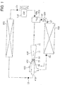
- a control valve 731 is disposed in a refrigerant passage between the radiator 200 and the ejector 400 to control an opening degree of the refrigerant passage based on a refrigerant heating degree (super-heating degree) at a refrigerant outlet side of the evaporator 300.
- the control valve 731 is a pressure-equalizing type which mechanically senses the refrigerant temperature at the refrigerant outlet side of the evaporator 300 and maintains the refrigerant heating degree at the refrigerant outlet side of the evaporator 300 at a predetermined degree.
- the control valve 731 has a temperature sensitive portion 731 a sensing the refrigerant temperature at the refrigerant outlet side of the evaporator 300, and a pressure-equalizing pipe 731b.
- the refrigerant flow amount Ge flowing into the evaporator 300 becomes larger.
- the increased pressure ⁇ P in the diffuser 430 of the ejector 400 is reduced when the refrigerant flow amount becomes larger and the flow amount ratio ⁇ (Ge/Gn) becomes larger. Therefore, as shown in FIG. 28 , the ejector efficiency n is changed in accordance with the heating degree at the refrigerant outlet side of the evaporator 300, and becomes maximum at a heating degree.
- the super-heating degree at the refrigerant outlet side of the evaporator 300 is controlled by the control valve 731 so that the ejector efficiency ⁇ becomes maximum.
- an electrical valve instead of the control valve 731, an electrical valve may be used so that a control target heating degree at the refrigerant outlet of the evaporator 300 is changed in accordance with the operation state of the ejector cycle system.
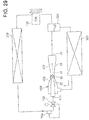
- a control valve 732 is disposed in a refrigerant passage between the radiator 200 and the ejector 400 to control a high-pressure side refrigerant pressure flowing from the radiator 200 based on a high-pressure side refrigerant temperature.
- the high-pressure side refrigerant pressure means the refrigerant pressure before being decompressed in the control valve 732 and the nozzle 410 of the ejector 400.
- the control valve 732 of the example has a temperature sensitive portion 732a which mechanically senses the refrigerant temperature at the refrigerant outlet side of the radiator 200.
- the control valve 732 controls the high-pressure side refrigerant pressure in accordance with the refrigerant temperature sensed by the temperature sensitive portion 732a.
- the refrigerant flow amount Gn flowing into the radiator 200 becomes smaller.
- the increased pressure ⁇ P in the diffuser 430 of the ejector 400 is reduced when the refrigerant flow amount Gn becomes smaller and the flow amount ratio ⁇ (Ge/Gn) becomes larger. Therefore, as shown in FIG. 30 , the ejector efficiency ⁇ is changed in accordance with the high-pressure side refrigerant pressure. That is, there is a high-pressure side refrigerant pressure at which the ejector efficiency ⁇ becomes maximum.
- the high-pressure side refrigerant pressure is controlled by the control valve 732 so that the ejector efficiency ⁇ becomes maximum.
- an electrical valve may be used instead of the control valve 732 operated mechanically.
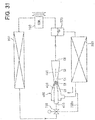
- a control valve 733 is disposed in a refrigerant passage between the radiator 200 and the ejector 400 to control a valve opening degree of the control valve 733 based on the pressure (heat load within the evaporator 300) within the evaporator 300.
- the control valve 733 mechanically senses the refrigerant pressure within the evaporator 300, and controls the valve opening degree in accordance with the sensed pressure.
- the control valve 733 has a pressure-equalizing pipe 733a. When the pressure within the evaporator 300 becomes larger, the valve opening degree of the control valve 733 becomes larger. Conversely, when the pressure within the evaporator 300 becomes smaller, the valve opening degree of the control valve 733 becomes smaller.
- the valve opening degree of the control valve 733 is controlled based on the pressure (heat load of the evaporator 300) within the evaporator 300. Therefore, even when the pressure within the evaporator 300 is changed, the valve opening degree of the control valve 733 is controlled so that the ejector efficiency ⁇ can be maintained at a high value.
- the valve opening degree of the control valve 733 becomes larger. Conversely, when the pressure within the evaporator 300 becomes smaller, the valve opening degree of the control valve 733 becomes smaller.
- the ejector efficiency ⁇ can be maintained at a high value while the flow amount of refrigerant flowing into the evaporator 300 can be suitably controlled.
- FIGS. 34 An embodiment of the present invention will be now described with reference to FIGS. 34 .
- a heat exchanger (i.e., inner heat exchanger) 800 in which refrigerant discharged from the radiator 200 and refrigerant sucked into the compressor 100 are heat-exchanged, is provided.
- FIG. 34 is an example where the heat exchanger 800 is provided in the ejector cycle system of the above-described seventeenth embodiment.
- FIG. 35 is an example where the heat exchanger 800 is provided in the ejector cycle system.
- FIG. 36 is an example where the heat exchanger 800 is provided in the ejector cycle system.
- Refrigerant flowing into the control valve 731-733 is cooled by the heat exchanger 800. Therefore, expansion energy in the nozzle 410 of the ejector 400 is reduced, the flow rate (flow speed) of refrigerant flowing from the nozzle 410 is decreased, and the dryness of refrigerant at the outlet of the nozzle 410 is decreased. Thus, the flow amount and flow speed of refrigerant sucked from the evaporator 300 to the ejector 400 are increased, and a flow speed difference between the refrigerant flow discharged from the nozzle 410 and the refrigerant flow sucked from the evaporator becomes smaller.
- an eddy loss with an eddy generated when the refrigerant sucked from the evaporator and refrigerant discharged from the nozzle 410 are mixed, can become smaller.
- the ejector efficiency n can be improved.
- FIG. 39 An embodiment of the present invention will be now described with reference to FIG. 39 .
- the control valve 731 disposed in the refrigerant passage between the ejector 400 and the radiator 200 is integrated with the nozzle 410, so that the ejector 400 and the control valve 731 are integrated. Because the control valve 731 is provided, refrigerant can be decompressed (throttled) at two steps of the control valve 731 and the nozzle 410 in the ejector 400.
- connection portions connecting a pressure equalizer and a temperature sensitive cylinder are provided.
- Carbon dioxide is used as refrigerant.
- the refrigerant pressure before being decompressed in the ejector 400 is equal to or higher than the critical pressure of refrigerant ethylene or ethane can also be used as a refrigerant.
- the ejector cycle system of the present invention is applied to a water heater.
- the ejector cycle system of the present invention may be applied to an air conditioner for the other use.
- the other compressor such as a volume-variable type compressor and a compressor having a constant rotation speed may be used.
- the shape and the structure of the ejector 400 can be changed.
- the throttle of the nozzle 410 may be constructed by plural steps.
Claims (4)
- Système à cycle d'éjection comprenant :un compresseur (100) pour aspirer et comprimer un fluide frigorigène ;un radiateur (200) pour refroidir le fluide frigorigène déchargé à partir du compresseur ;un évaporateur (300) dans lequel le fluide frigorigène est évaporé en absorbant de la chaleur ;un éjecteur (400) qui décomprime et étend le fluide frigorigène provenant du radiateur pour aspirer un gaz frigorigène évaporé dans l'évaporateur, et convertit une énergie d'expansion en une énergie de pression pour augmenter la pression du fluide frigorigène à aspirer dans le compresseur ; etun séparateur gaz-liquide (500) pour stocker le fluide frigorigène et pour séparer le fluide frigorigène provenant de l'éjecteur (400) en un gaz frigorigène et un liquide frigorigène,dans lequel le séparateur gaz-liquide est disposé pour séparer le gaz frigorigène et le liquide frigorigène l'un de l'autre de manière que le gaz frigorigène dans le séparateur gaz-liquide soit délivré à un côté aspiration du compresseur (100) et le liquide frigorigène dans le séparateur gaz-liquide soit délivré à l'évaporateur, le système à cycle d'éjection étant caractérisé en ce qu'il comprend en outre :une vanne de commande (731) qui est disposée dans un passage de fluide frigorigène entre le radiateur (200) et l'éjecteur (400), ayant un moyen de détection de surchauffe (731a, 731b) détectant la température du fluide frigorigène au niveau du côté de sortie de fluide frigorigène de l'évaporateur (300) et commande un degré d'ouverture du passage de fluide frigorigène sur la base d'un degré de surchauffe prédéterminé du fluide frigorigène au niveau d'un côté de sortie de l'évaporateur (300) de manière que le rendement de l'éjecteur devienne maximal au degré de surchauffe prédéterminé, dans lequel le système à cycle d'éjection étant adapté pour, durant l'utilisation, avoir la pression de fluide frigorigène, avant d'être décomprimé dans l'éjecteur (400), égale ou supérieure à la pression critique du fluide frigorigène,le fluide frigorigène est du dioxyde de carbone, de l'éthylène ou de l'éthane, etla pression du fluide frigorigène au niveau du côté de sortie de l'évaporateur est inférieure à la pression critique du fluide frigorigène.
- Système à cycle d'éjection selon la revendication 1, dans lequel la vanne de commande (731, 732) et l'éjecteur (400) sont intégrés.
- Système à cycle d'éjection selon la revendication 2, dans lequel :l'éjecteur comprend une buse (410) dans laquelle une énergie de pression du fluide frigorigène à haute pression s'écoulant à partir du radiateur est convertie en une énergie de vitesse de manière que le fluide frigorigène soit décomprimé et étendu, et une portion d'augmentation de pression (420, 430) dans laquelle l'énergie de vitesse est convertie en énergie de pression de manière que la pression du fluide frigorigène soit augmentée alors que le fluide frigorigène déchargé à partir de la buse et le fluide frigorigène aspiré à partir de l'évaporateur sont mélangés ; etla vanne de commande est intégrée avec la buse.
- Système à cycle selon l'une quelconque des revendications 1 à 3, comprenant en outre :un échangeur de chaleur intérieur (800) qui est disposé pour effectuer un échange de chaleur entre le fluide frigorigène s'écoulant du radiateur (200) vers l'éjecteur (400) et le fluide frigorigène délivré à partir du séparateur gaz-liquide (500) vers le compresseur (100).
Applications Claiming Priority (11)
| Application Number | Priority Date | Filing Date | Title |
|---|---|---|---|
| JP2000077827 | 2000-03-15 | ||
| JP2000077827 | 2000-03-15 | ||
| JP2000237344 | 2000-08-04 | ||
| JP2000237344 | 2000-08-04 | ||
| JP2000273585 | 2000-09-08 | ||
| JP2000273585 | 2000-09-08 | ||
| JP2000387618 | 2000-12-20 | ||
| JP2000387618 | 2000-12-20 | ||
| JP2001005196 | 2001-01-12 | ||
| JP2001005196 | 2001-01-12 | ||
| EP01105442.6A EP1134517B1 (fr) | 2000-03-15 | 2001-03-13 | Système à cycle d'éjection avec pression critique du fluide frigorigène |
Related Parent Applications (2)
| Application Number | Title | Priority Date | Filing Date |
|---|---|---|---|
| EP01105442.6A Division EP1134517B1 (fr) | 2000-03-15 | 2001-03-13 | Système à cycle d'éjection avec pression critique du fluide frigorigène |
| EP01105442.6A Division-Into EP1134517B1 (fr) | 2000-03-15 | 2001-03-13 | Système à cycle d'éjection avec pression critique du fluide frigorigène |
Publications (3)
| Publication Number | Publication Date |
|---|---|
| EP1589301A2 EP1589301A2 (fr) | 2005-10-26 |
| EP1589301A3 EP1589301A3 (fr) | 2006-03-22 |
| EP1589301B1 true EP1589301B1 (fr) | 2017-06-14 |
Family
ID=27531455
Family Applications (2)
| Application Number | Title | Priority Date | Filing Date |
|---|---|---|---|
| EP05016204.9A Expired - Lifetime EP1589301B1 (fr) | 2000-03-15 | 2001-03-13 | Système à cycle d'éjection avec pression critique du fluide frigorigène |
| EP01105442.6A Expired - Lifetime EP1134517B1 (fr) | 2000-03-15 | 2001-03-13 | Système à cycle d'éjection avec pression critique du fluide frigorigène |
Family Applications After (1)
| Application Number | Title | Priority Date | Filing Date |
|---|---|---|---|
| EP01105442.6A Expired - Lifetime EP1134517B1 (fr) | 2000-03-15 | 2001-03-13 | Système à cycle d'éjection avec pression critique du fluide frigorigène |
Country Status (6)
| Country | Link |
|---|---|
| US (2) | US6477857B2 (fr) |
| EP (2) | EP1589301B1 (fr) |
| KR (1) | KR100413095B1 (fr) |
| CN (1) | CN1313786C (fr) |
| AU (1) | AU747941B2 (fr) |
| BR (1) | BR0101084A (fr) |
Families Citing this family (138)
| Publication number | Priority date | Publication date | Assignee | Title |
|---|---|---|---|---|
| JP4770474B2 (ja) | 2006-01-20 | 2011-09-14 | 株式会社デンソー | エジェクタ式冷凍サイクル用ユニットおよびその製造方法 |
| JP3818115B2 (ja) | 2001-10-04 | 2006-09-06 | 株式会社デンソー | エジェクタサイクル |
| JP4032875B2 (ja) | 2001-10-04 | 2008-01-16 | 株式会社デンソー | エジェクタサイクル |
| JP3945252B2 (ja) * | 2002-01-10 | 2007-07-18 | 株式会社デンソー | エジェクタサイクル用の気液分離器 |
| JP3941602B2 (ja) * | 2002-02-07 | 2007-07-04 | 株式会社デンソー | エジェクタ方式の減圧装置 |
| JP3928471B2 (ja) * | 2002-04-26 | 2007-06-13 | 株式会社デンソー | 車両用空調装置 |
| JP3928470B2 (ja) * | 2002-04-26 | 2007-06-13 | 株式会社デンソー | 車両用空調装置 |
| JP4522641B2 (ja) * | 2002-05-13 | 2010-08-11 | 株式会社デンソー | 蒸気圧縮式冷凍機 |
| JP2003329336A (ja) * | 2002-05-13 | 2003-11-19 | Denso Corp | 蒸気圧縮式冷凍サイクル用の気液分離器及びエジェクタサイクル |
| US6904769B2 (en) * | 2002-05-15 | 2005-06-14 | Denso Corporation | Ejector-type depressurizer for vapor compression refrigeration system |
| US6647742B1 (en) * | 2002-05-29 | 2003-11-18 | Carrier Corporation | Expander driven motor for auxiliary machinery |
| JP4120296B2 (ja) | 2002-07-09 | 2008-07-16 | 株式会社デンソー | エジェクタおよびエジェクタサイクル |
| JP2004044906A (ja) * | 2002-07-11 | 2004-02-12 | Denso Corp | エジェクタサイクル |
| JP3951840B2 (ja) * | 2002-07-16 | 2007-08-01 | 株式会社デンソー | 冷凍サイクル装置 |
| JP4075530B2 (ja) * | 2002-08-29 | 2008-04-16 | 株式会社デンソー | 冷凍サイクル |
| JP4110895B2 (ja) * | 2002-09-09 | 2008-07-02 | 株式会社デンソー | 空調装置および車両用空調装置 |
| JP4000966B2 (ja) * | 2002-09-12 | 2007-10-31 | 株式会社デンソー | 蒸気圧縮式冷凍機 |
| JP2004116938A (ja) * | 2002-09-27 | 2004-04-15 | Denso Corp | エジェクタサイクル |
| JP3863480B2 (ja) * | 2002-10-31 | 2006-12-27 | 松下電器産業株式会社 | 冷凍サイクル装置 |
| JP4232484B2 (ja) * | 2003-03-05 | 2009-03-04 | 株式会社日本自動車部品総合研究所 | エジェクタおよび蒸気圧縮式冷凍機 |
| US6918266B2 (en) * | 2003-04-21 | 2005-07-19 | Denso Corporation | Ejector for vapor-compression refrigerant cycle |
| JP4285060B2 (ja) * | 2003-04-23 | 2009-06-24 | 株式会社デンソー | 蒸気圧縮式冷凍機 |
| JP4114554B2 (ja) * | 2003-06-18 | 2008-07-09 | 株式会社デンソー | エジェクタサイクル |
| JP4001065B2 (ja) * | 2003-06-30 | 2007-10-31 | 株式会社デンソー | エジェクタサイクル |
| JP2005037093A (ja) * | 2003-07-18 | 2005-02-10 | Tgk Co Ltd | 冷凍サイクル |
| US6851277B1 (en) * | 2003-08-27 | 2005-02-08 | Carrier Corporation | Economizer chamber for minimizing pressure pulsations |
| JP4140488B2 (ja) * | 2003-09-09 | 2008-08-27 | ダイキン工業株式会社 | スクリュー圧縮機および冷凍装置 |
| JP4273977B2 (ja) * | 2004-01-21 | 2009-06-03 | 株式会社デンソー | エジェクタサイクル |
| US7131292B2 (en) * | 2004-02-18 | 2006-11-07 | Denso Corporation | Gas-liquid separator |
| CN1291196C (zh) * | 2004-02-18 | 2006-12-20 | 株式会社电装 | 具有多蒸发器的喷射循环 |
| US7254961B2 (en) | 2004-02-18 | 2007-08-14 | Denso Corporation | Vapor compression cycle having ejector |
| JP4984453B2 (ja) * | 2004-09-22 | 2012-07-25 | 株式会社デンソー | エジェクタ式冷凍サイクル |
| JP4581720B2 (ja) | 2004-09-29 | 2010-11-17 | 株式会社デンソー | エジェクタを用いたサイクル |
| US7600390B2 (en) * | 2004-10-21 | 2009-10-13 | Tecumseh Products Company | Method and apparatus for control of carbon dioxide gas cooler pressure by use of a two-stage compressor |
| JP4415835B2 (ja) * | 2004-11-24 | 2010-02-17 | 株式会社デンソー | 車両用冷凍サイクル装置 |
| EP1666817A3 (fr) * | 2004-12-01 | 2007-01-17 | Fujikoki Corporation | Vanne de régulation de pression |
| JP4600208B2 (ja) * | 2005-01-20 | 2010-12-15 | 株式会社デンソー | エジェクタを用いたサイクル |
| JP4595607B2 (ja) * | 2005-03-18 | 2010-12-08 | 株式会社デンソー | エジェクタを使用した冷凍サイクル |
| JP4626531B2 (ja) * | 2005-04-01 | 2011-02-09 | 株式会社デンソー | エジェクタ式冷凍サイクル |
| CN100580344C (zh) * | 2005-04-05 | 2010-01-13 | 株式会社电装 | 用于喷射器型制冷循环的单元 |
| JP4259531B2 (ja) * | 2005-04-05 | 2009-04-30 | 株式会社デンソー | エジェクタ式冷凍サイクル用ユニット |
| US20060254308A1 (en) * | 2005-05-16 | 2006-11-16 | Denso Corporation | Ejector cycle device |
| DE102006024211A1 (de) * | 2005-05-24 | 2007-01-25 | Denso Corp., Kariya | Ejektorpumpe und Ejektorpumpenkreisvorrichtung |
| CN101344336A (zh) * | 2005-06-30 | 2009-01-14 | 株式会社电装 | 喷射器循环系统 |
| DE102006062834B4 (de) * | 2005-06-30 | 2016-07-14 | Denso Corporation | Ejektorkreislaufsystem |
| JP4600200B2 (ja) * | 2005-08-02 | 2010-12-15 | 株式会社デンソー | エジェクタ式冷凍サイクル |
| CN100436962C (zh) * | 2005-08-04 | 2008-11-26 | 株式会社电装 | 具有喷射器的致冷循环装置 |
| JP4661449B2 (ja) * | 2005-08-17 | 2011-03-30 | 株式会社デンソー | エジェクタ式冷凍サイクル |
| US7367202B2 (en) * | 2005-08-17 | 2008-05-06 | Denso Corporation | Refrigerant cycle device with ejector |
| JP2007051833A (ja) | 2005-08-18 | 2007-03-01 | Denso Corp | エジェクタ式冷凍サイクル |
| US7850712B2 (en) * | 2005-11-15 | 2010-12-14 | Ethicon Endo-Surgery, Inc. | Self-shielding suture anchor |
| JP2007163016A (ja) * | 2005-12-13 | 2007-06-28 | Denso Corp | エジェクタ式冷凍サイクルおよびエジェクタ式冷凍サイクルの制御方法 |
| JP4897284B2 (ja) * | 2005-12-13 | 2012-03-14 | サンデン株式会社 | 冷凍サイクル |
| JP4737001B2 (ja) * | 2006-01-13 | 2011-07-27 | 株式会社デンソー | エジェクタ式冷凍サイクル |
| JP4692295B2 (ja) * | 2006-01-19 | 2011-06-01 | 株式会社デンソー | 蒸発器ユニットおよびエジェクタ式冷凍サイクル |
| JP4548350B2 (ja) * | 2006-01-20 | 2010-09-22 | 株式会社デンソー | エジェクタ式冷凍サイクル用ユニット |
| JP2007192502A (ja) * | 2006-01-20 | 2007-08-02 | Denso Corp | 熱交換器 |
| JP2007218497A (ja) * | 2006-02-16 | 2007-08-30 | Denso Corp | エジェクタ式冷凍サイクルおよび冷媒流量制御装置 |
| KR101162756B1 (ko) * | 2007-02-24 | 2012-07-05 | 삼성전자주식회사 | 수냉식 공기조화기 및 그 제어방법 |
| CN101457996B (zh) * | 2007-12-13 | 2011-05-25 | 株式会社电装 | 制冷循环装置 |
| JP4557031B2 (ja) * | 2008-03-27 | 2010-10-06 | 株式会社デンソー | 車両用空調装置 |
| CN101952670B (zh) * | 2008-04-18 | 2013-04-17 | 株式会社电装 | 喷射器式制冷循环装置 |
| JP5446694B2 (ja) * | 2008-12-15 | 2014-03-19 | 株式会社デンソー | エジェクタ式冷凍サイクル |
| WO2010126980A2 (fr) * | 2009-04-29 | 2010-11-04 | Carrier Corporation | Système de refroidissement, de chauffage et de réfrigération à activation thermique transcritique |
| US8434324B2 (en) * | 2010-04-05 | 2013-05-07 | Denso Corporation | Evaporator unit |
| DE102010031388A1 (de) * | 2010-07-15 | 2012-01-19 | Behr Gmbh & Co. Kg | Expansionselement für ein System zur Luftkonditionierung für ein Kraftfahrzeug |
| WO2012012490A2 (fr) | 2010-07-23 | 2012-01-26 | Carrier Corporation | Cycle d'éjection |
| WO2012012496A2 (fr) * | 2010-07-23 | 2012-01-26 | Carrier Corporation | Séparateur de réfrigérant à cycle d'éjection |
| US9759462B2 (en) | 2010-07-23 | 2017-09-12 | Carrier Corporation | High efficiency ejector cycle |
| JP5625610B2 (ja) | 2010-08-18 | 2014-11-19 | 株式会社デンソー | エジェクタ式冷凍サイクル本発明は、エジェクタを備えるエジェクタ式冷凍サイクルに関する。 |
| JP5533483B2 (ja) | 2010-09-16 | 2014-06-25 | 株式会社デンソー | 圧縮機のトルク推定装置 |
| CN102183104B (zh) * | 2011-03-31 | 2012-07-04 | 浙江大学 | 一种间膨式太阳能辅助多功能热泵系统 |
| EP2715253B1 (fr) * | 2011-05-23 | 2019-11-06 | Carrier Corporation | Éjecteurs et leurs procédés de fabrication |
| CN103620322B (zh) * | 2011-06-10 | 2016-05-18 | 开利公司 | 具有主动流漩涡的喷射器 |
| CN102305500B (zh) * | 2011-06-25 | 2013-06-26 | 马建宏 | 一种高能效比制冷装置 |
| CN102374694B (zh) * | 2011-07-11 | 2013-06-19 | 中国科学院广州能源研究所 | Co2多级喷射循环热泵、空调系统 |
| GB2511666B (en) | 2011-11-30 | 2016-06-29 | Mitsubishi Electric Corp | Refrigeration cycle device with function of returning lubricating oil to compressor, equipment, and refrigeration cycle method |
| JP5920110B2 (ja) | 2012-02-02 | 2016-05-18 | 株式会社デンソー | エジェクタ |
| CN102997383A (zh) * | 2012-02-28 | 2013-03-27 | 张育仁 | 一种空调压缩机出口能量的回收和利用方法 |
| US9046289B2 (en) | 2012-04-10 | 2015-06-02 | Thermo King Corporation | Refrigeration system |
| CN103375953B (zh) * | 2012-04-27 | 2016-02-10 | 珠海格力电器股份有限公司 | 气液分离器及具有其的空调系统 |
| JP5817663B2 (ja) * | 2012-07-09 | 2015-11-18 | 株式会社デンソー | エジェクタ |
| CN102914114B (zh) * | 2012-11-12 | 2014-12-17 | 重庆大学 | 独立便携式家庭制冷系统双循环一体机 |
| JP6083330B2 (ja) * | 2012-11-16 | 2017-02-22 | 株式会社デンソー | エジェクタ |
| CN103041608B (zh) * | 2012-12-06 | 2015-01-07 | 温州市日中轻工机械有限公司 | 蒸发器出料闪冷装置及其使用方法 |
| JP6090104B2 (ja) * | 2012-12-13 | 2017-03-08 | 株式会社デンソー | エジェクタ |
| JP5999071B2 (ja) | 2012-12-27 | 2016-09-28 | 株式会社デンソー | エジェクタ |
| JP6119566B2 (ja) | 2012-12-27 | 2017-04-26 | 株式会社デンソー | エジェクタ |
| US9803934B2 (en) | 2013-01-25 | 2017-10-31 | Trane International Inc. | Refrigerant outlet device of a condenser |
| JP6119489B2 (ja) | 2013-07-30 | 2017-04-26 | 株式会社デンソー | エジェクタ |
| JP6186998B2 (ja) * | 2013-07-31 | 2017-08-30 | 株式会社デンソー | 車両用空調装置 |
| CN103542570B (zh) * | 2013-10-30 | 2016-02-10 | 上海交通大学 | 具有自动除霜和回油功能的喷射循环 |
| KR101359932B1 (ko) | 2013-12-20 | 2014-02-11 | 오텍캐리어냉장 유한회사 | 이젝터를 이용한 냉동탑차의 냉동-냉방 시스템 |
| JP6176127B2 (ja) | 2014-01-21 | 2017-08-09 | 株式会社デンソー | エジェクタ |
| JP6459807B2 (ja) * | 2014-08-28 | 2019-01-30 | 株式会社デンソー | エジェクタ式冷凍サイクル |
| JP2016048156A (ja) * | 2014-08-28 | 2016-04-07 | 株式会社デンソー | エジェクタ式冷凍サイクル |
| JP6319041B2 (ja) * | 2014-10-24 | 2018-05-09 | 株式会社デンソー | エジェクタ式冷凍サイクル |
| JP6319043B2 (ja) | 2014-10-24 | 2018-05-09 | 株式会社デンソー | エジェクタ式冷凍サイクル |
| CN104344592A (zh) * | 2014-11-07 | 2015-02-11 | 西安交通大学 | 一种蒸气压缩制冷用带喷射器的冷凝器单元 |
| CN104501481A (zh) * | 2014-12-18 | 2015-04-08 | 天津商业大学 | 一种co2双节流引射制冷系统 |
| EP3334985B1 (fr) | 2015-08-14 | 2019-05-01 | Danfoss A/S | Système à compression de vapeur doté d'au moins deux groupes évaporateurs |
| CN105135733B (zh) * | 2015-08-31 | 2017-08-29 | 黑龙江爱科德科技有限公司 | 半满液式二氧化碳制冷系统 |
| CA2997658A1 (fr) | 2015-10-20 | 2017-04-27 | Danfoss A/S | Procede de commande de systeme a compression de vapeur a valeur de reglage variable de pression de recepteur |
| PL3365620T3 (pl) | 2015-10-20 | 2020-01-31 | Danfoss A/S | Sposób sterowania układem sprężania pary w stanie zalanym |
| BR112018007270A2 (pt) * | 2015-10-20 | 2018-10-30 | Danfoss As | método para controlar um sistema de compressão a vapor em modo ejetor por um tempo prolongado |
| FR3049270B1 (fr) * | 2016-03-22 | 2019-09-27 | Arkema France | Recipient pour le stockage d'une composition comprenant du tetrafluoropropene et methode de stockage de celle-ci |
| CN106247508B (zh) * | 2016-09-12 | 2019-03-05 | 青岛海信日立空调系统有限公司 | 采用喷射器的空调热泵系统、空调器及空调器控制方法 |
| CN106500383B (zh) * | 2016-10-27 | 2019-07-05 | 山东大学 | 一种喷射器运行区间的优化控制方法 |
| DE102016123277A1 (de) * | 2016-12-01 | 2018-06-07 | Wurm Gmbh & Co. Kg Elektronische Systeme | Kälteanlage und Verfahren zur Regelung einer Kälteanlage |
| CN106596158B (zh) * | 2016-12-02 | 2019-12-10 | 合肥天时测控技术有限公司 | 一种能量回收型空调制冷设备焓差试验室 |
| CN106642856B (zh) * | 2016-12-16 | 2019-07-12 | 珠海格力电器股份有限公司 | 一种喷液电磁阀的控制方法、装置及空调 |
| CN106524502B (zh) * | 2016-12-19 | 2019-05-07 | 西安交通大学 | 直膨式太阳能辅助的喷射器增效热泵热水系统及控制方法 |
| CN108224833A (zh) * | 2016-12-21 | 2018-06-29 | 开利公司 | 喷射器制冷系统及其控制方法 |
| JP2018178781A (ja) * | 2017-04-05 | 2018-11-15 | 株式会社デンソー | エジェクタ及びこれを用いた燃料電池システム並びに冷凍サイクルシステム |
| CN106969558A (zh) * | 2017-04-21 | 2017-07-21 | 美的集团股份有限公司 | 制冷系统和制冷系统的换热方法 |
| CN107024040A (zh) * | 2017-04-24 | 2017-08-08 | 美的集团股份有限公司 | 喷射器节流制冷系统和引流方法 |
| WO2019060752A1 (fr) | 2017-09-25 | 2019-03-28 | Johnson Controls Technology Company | Système d'éjecteur moteur à huile à deux étapes |
| CN107990580B (zh) * | 2017-11-07 | 2019-05-10 | 西安交通大学 | 一种多次分离喷射增效的自复叠热泵系统及运行模式 |
| RU2019103187A (ru) | 2018-02-06 | 2020-08-05 | Кэрриер Корпорейшн | Рекуперация энергии от горячего газа в перепускной линии |
| CN108375233A (zh) * | 2018-04-19 | 2018-08-07 | 天津商业大学 | 一种带回热和喷射降压的复叠式制冷系统 |
| WO2019231400A1 (fr) * | 2018-05-30 | 2019-12-05 | National University Of Singapore | Système de refroidissement et de puissance combiné et procédé |
| CN109059351A (zh) * | 2018-06-19 | 2018-12-21 | 李华玉 | 第三类热驱动压缩式热泵 |
| CN109307377B (zh) * | 2018-09-20 | 2020-05-26 | 西安交通大学 | 采用喷射器增效的两级自复叠制冷循环系统及循环方法 |
| DK180146B1 (en) | 2018-10-15 | 2020-06-25 | Danfoss As Intellectual Property | Heat exchanger plate with strenghened diagonal area |
| AU2019374813A1 (en) * | 2018-11-06 | 2021-05-27 | Evapco, Inc. | Direct expansion evaporator with vapor ejector capacity boost |
| CN110953750A (zh) * | 2018-11-12 | 2020-04-03 | 李华玉 | 高效蒸汽压缩式热泵 |
| CN109827363A (zh) * | 2019-01-25 | 2019-05-31 | 中国科学院理化技术研究所 | 气冷器组合温控装置、co2制冷热泵系统及其温控方法 |
| CN111520928B (zh) | 2019-02-02 | 2023-10-24 | 开利公司 | 增强热驱动的喷射器循环 |
| CN111520932B8 (zh) | 2019-02-02 | 2023-07-04 | 开利公司 | 热回收增强制冷系统 |
| CN110274403A (zh) * | 2019-06-26 | 2019-09-24 | 太原理工大学 | 喷射器增效的准二级压缩循环系统 |
| CN110398131B (zh) * | 2019-07-24 | 2020-06-02 | 西安交通大学 | 一种引射式冷能回收低温冷却装置 |
| WO2021113423A1 (fr) * | 2019-12-04 | 2021-06-10 | Bechtel Hydrocarbon Technology Solutions, Inc. | Systèmes et procédés de mise en œuvre de cycles de réfrigération d'éjecteur avec des étages d'évaporation en cascade |
| CN112984855A (zh) * | 2021-03-31 | 2021-06-18 | 广东积微科技有限公司 | 一种热泵空调系统及控制逻辑 |
| CN113513854A (zh) * | 2021-08-09 | 2021-10-19 | 上海海洋大学 | 一种具有高压喷射器的跨临界co2机械过冷制冷系统 |
| US20230182535A1 (en) * | 2021-12-14 | 2023-06-15 | Ford Global Technologies, Llc | Heat pump for a vehicle |
| US11725858B1 (en) | 2022-03-08 | 2023-08-15 | Bechtel Energy Technologies & Solutions, Inc. | Systems and methods for regenerative ejector-based cooling cycles |
| WO2023198787A1 (fr) * | 2022-04-15 | 2023-10-19 | John Bean Technologies Ab | Estimation de capacité de réfrigération par mesure de différence de température d'air et/ou d'écoulement d'air |
| CN114608050A (zh) * | 2022-04-16 | 2022-06-10 | 哈尔滨工业大学 | 带喷射器的平行压缩跨临界co2空气源热泵供暖系统 |
Citations (4)
| Publication number | Priority date | Publication date | Assignee | Title |
|---|---|---|---|---|
| US3557566A (en) * | 1967-07-27 | 1971-01-26 | Philips Corp | Method and device for producing cold and liquefying gases |
| US5245836A (en) * | 1989-01-09 | 1993-09-21 | Sinvent As | Method and device for high side pressure regulation in transcritical vapor compression cycle |
| JPH05312421A (ja) * | 1992-05-14 | 1993-11-22 | Nippondenso Co Ltd | 冷凍装置 |
| JPH0875284A (ja) * | 1994-09-09 | 1996-03-19 | Hitachi Ltd | 極低温冷凍装置 |
Family Cites Families (28)
| Publication number | Priority date | Publication date | Assignee | Title |
|---|---|---|---|---|
| US1836318A (en) * | 1926-07-26 | 1931-12-15 | Norman H Gay | Refrigerating system |
| US1958087A (en) * | 1930-04-05 | 1934-05-08 | Baker Ice Machine Company Inc | Automatic control for refrigeration systems |
| CH157423A (de) * | 1931-03-24 | 1932-09-30 | Fuelscher Johann | Kälteanlage. |
| US2512869A (en) * | 1948-04-24 | 1950-06-27 | James C Mcbroom | Method and apparatus for circulating refrigerants |
| US3277660A (en) * | 1965-12-13 | 1966-10-11 | Kaye & Co Inc Joseph | Multiple-phase ejector refrigeration system |
| NL6607168A (fr) * | 1966-05-25 | 1967-11-27 | ||
| NL6609175A (fr) * | 1966-07-01 | 1968-01-02 | ||
| NL147251B (nl) * | 1966-07-01 | 1975-09-15 | Philips Nv | Ejecteur, in het bijzonder geschikt voor een inrichting voor het verwekken van koude en/of voor het vloeibaar maken van gassen. |
| NL6710359A (fr) * | 1967-07-27 | 1969-01-29 | ||
| US3488678A (en) * | 1968-05-03 | 1970-01-06 | Parker Hannifin Corp | Suction accumulator for refrigeration systems |
| US3670519A (en) * | 1971-02-08 | 1972-06-20 | Borg Warner | Capacity control for multiple-phase ejector refrigeration systems |
| US3701264A (en) * | 1971-02-08 | 1972-10-31 | Borg Warner | Controls for multiple-phase ejector refrigeration systems |
| US4187695A (en) * | 1978-11-07 | 1980-02-12 | Virginia Chemicals Inc. | Air-conditioning system having recirculating and flow-control means |
| DE3204784A1 (de) * | 1982-02-11 | 1983-08-25 | Siemens AG, 1000 Berlin und 8000 München | Fluessigkeitsringvakuumpumpe mit vorgeschaltetem vorverdichter |
| US4528822A (en) * | 1984-09-07 | 1985-07-16 | American-Standard Inc. | Heat pump refrigeration circuit with liquid heating capability |
| SU1726928A1 (ru) * | 1989-11-13 | 1992-04-15 | Рыбинский Авиационный Технологический Институт | Холодильна установка |
| DE4036854C1 (fr) * | 1990-11-19 | 1992-05-21 | Thermal-Werke, Waerme-, Kaelte-, Klimatechnik Gmbh, 6832 Hockenheim, De | |
| JPH04316962A (ja) | 1991-04-15 | 1992-11-09 | Nippondenso Co Ltd | 冷凍サイクル |
| JP3331604B2 (ja) * | 1991-11-27 | 2002-10-07 | 株式会社デンソー | 冷凍サイクル装置 |
| JP3219108B2 (ja) * | 1992-06-29 | 2001-10-15 | 株式会社デンソー | 冷凍サイクル |
| US5343711A (en) * | 1993-01-04 | 1994-09-06 | Virginia Tech Intellectual Properties, Inc. | Method of reducing flow metastability in an ejector nozzle |
| US5493875A (en) * | 1994-08-01 | 1996-02-27 | Kozinski; Richard C. | Vehicle air conditioning system utilizing refrigerant recirculation within the evaporatorccumulator circuit |
| US5551255A (en) * | 1994-09-27 | 1996-09-03 | The United States Of America As Represented By The Secretary Of Commerce | Accumulator distillation insert for zeotropic refrigerant mixtures |
| JPH09318169A (ja) * | 1996-03-28 | 1997-12-12 | Mitsubishi Electric Corp | 冷凍装置 |
| JP3690030B2 (ja) | 1997-01-22 | 2005-08-31 | 株式会社デンソー | 冷凍装置 |
| US5857347A (en) * | 1997-03-04 | 1999-01-12 | Frigoscandia Equipment Ab | Refrigeration system and a separator therefor |
| JPH11351680A (ja) * | 1998-06-08 | 1999-12-24 | Calsonic Corp | 冷房装置 |
| KR100310772B1 (ko) * | 1998-08-06 | 2002-06-20 | 윤덕용 | 차량용쾌속초기냉방장치 |
-
2001
- 2001-03-13 EP EP05016204.9A patent/EP1589301B1/fr not_active Expired - Lifetime
- 2001-03-13 EP EP01105442.6A patent/EP1134517B1/fr not_active Expired - Lifetime
- 2001-03-13 US US09/805,414 patent/US6477857B2/en not_active Expired - Lifetime
- 2001-03-14 KR KR10-2001-0013181A patent/KR100413095B1/ko active IP Right Grant
- 2001-03-15 BR BR0101084-0A patent/BR0101084A/pt not_active IP Right Cessation
- 2001-03-15 AU AU28020/01A patent/AU747941B2/en not_active Ceased
- 2001-03-15 CN CNB011094915A patent/CN1313786C/zh not_active Expired - Lifetime
-
2002
- 2002-07-23 US US10/201,057 patent/US6574987B2/en not_active Expired - Lifetime
Patent Citations (4)
| Publication number | Priority date | Publication date | Assignee | Title |
|---|---|---|---|---|
| US3557566A (en) * | 1967-07-27 | 1971-01-26 | Philips Corp | Method and device for producing cold and liquefying gases |
| US5245836A (en) * | 1989-01-09 | 1993-09-21 | Sinvent As | Method and device for high side pressure regulation in transcritical vapor compression cycle |
| JPH05312421A (ja) * | 1992-05-14 | 1993-11-22 | Nippondenso Co Ltd | 冷凍装置 |
| JPH0875284A (ja) * | 1994-09-09 | 1996-03-19 | Hitachi Ltd | 極低温冷凍装置 |
Non-Patent Citations (4)
| Title |
|---|
| DOBROVICESCU A: "ATTEMPTS IN THE REDUCTION OF ENERGY DESTRUCTION IN REFRIGERATION SYSTEMS", IIR INTERNATIONAL MEETING PREPRINTS, XX, XX, 10 September 1996 (1996-09-10), pages 222 - 230, XP001168664 * |
| DOMANSKI P A: "REFRIGERANTS FOR THE 21ST CENTURY ASHRAE/NIST REFRIGERANTS CONFERENCE", NATIONAL INSTITUTE OF STANDARDS AND TECHNOLOGY. JOURNAL OF RESEARCH, U.S. DEPARTMENT OF COMMERCE, NATIONAL INSTITUTE OF STANDARDS AND TECHNOLOGY, US, vol. 103, no. 5, 1 January 1998 (1998-01-01), pages 1 - 05,766, XP001169068, ISSN: 1044-677X * |
| HEYL P ET AL: "EXPANDER-COMPRESSOR FOR A MORE EFFICIENT USE OF CO2 AS REFRIGERANT", IIR - GUSTAV LORENTZEN CONFERENCE ON NATURAL WORKING FLUIDS.PROCEEDINGS, XX, XX, 2 June 1998 (1998-06-02), pages 240 - 248, XP001169050 * |
| RIETDIJK J A ED - INSTITUT INTERNATIONAL DU FROID: "THE EXPANSION-EJECTOR, A NEW DEVICE FOR LIQUEFACTION AND REFRIGERATION AT 4 DEG K AND LOWER//L'EJECTEUR-DETENDEUR, UN NOUVEAU SYSTEME DE REFRIGERATION ET DE LIQUEFACTION A 4 DEG K ET PLUS BAS", 1 January 1966, LIQUID HELIUM TECHNOLOGY. HEAT TRANSFER, CRYOSTATS, LIQUEFIERS, REFRIGERATERS AND STORAGE, NUCLEAR PHYSICS, SPACE OPERATIONS, ELECTROMAGNETIC TECHNOLOGY, PARIS, INSTITUT INTERNATIONAL DU FROID, FR, PAGE(S) 241 - 249, XP008036376 * |
Also Published As
| Publication number | Publication date |
|---|---|
| EP1589301A3 (fr) | 2006-03-22 |
| US6477857B2 (en) | 2002-11-12 |
| EP1134517A3 (fr) | 2002-07-10 |
| EP1134517B1 (fr) | 2017-07-26 |
| CN1316636A (zh) | 2001-10-10 |
| AU747941B2 (en) | 2002-05-30 |
| US20020184903A1 (en) | 2002-12-12 |
| EP1134517A2 (fr) | 2001-09-19 |
| CN1313786C (zh) | 2007-05-02 |
| EP1589301A2 (fr) | 2005-10-26 |
| US6574987B2 (en) | 2003-06-10 |
| BR0101084A (pt) | 2001-10-30 |
| US20010025499A1 (en) | 2001-10-04 |
| KR100413095B1 (ko) | 2003-12-31 |
| AU2802001A (en) | 2001-09-20 |
| KR20010092335A (ko) | 2001-10-24 |
Similar Documents
| Publication | Publication Date | Title |
|---|---|---|
| EP1589301B1 (fr) | Système à cycle d'éjection avec pression critique du fluide frigorigène | |
| EP1273859B1 (fr) | Système à cycle d'éjection | |
| JP3331604B2 (ja) | 冷凍サイクル装置 | |
| US7779647B2 (en) | Ejector and ejector cycle device | |
| EP1300638B1 (fr) | Système à cycle d'éjection | |
| US6966199B2 (en) | Ejector with throttle controllable nozzle and ejector cycle using the same | |
| US8047018B2 (en) | Ejector cycle system | |
| US7987685B2 (en) | Refrigerant cycle device with ejector | |
| JP4254217B2 (ja) | エジェクタサイクル | |
| JP4285060B2 (ja) | 蒸気圧縮式冷凍機 | |
| US20040007014A1 (en) | Ejector cycle | |
| US20070039350A1 (en) | Refrigerant cycle device with ejector and refrigerant branch structure for the same | |
| US20090229305A1 (en) | Vapor compression refrigerating cycle apparatus | |
| US6925835B2 (en) | Ejector cycle | |
| US8650904B2 (en) | Ejector-type refrigerant cycle device | |
| US6807819B2 (en) | Vapor compression refrigerant cycle | |
| JP2005351548A (ja) | 蒸気噴射式冷凍装置 | |
| JP2008075926A (ja) | エジェクタ式冷凍サイクル |
Legal Events
| Date | Code | Title | Description |
|---|---|---|---|
| PUAI | Public reference made under article 153(3) epc to a published international application that has entered the european phase |
Free format text: ORIGINAL CODE: 0009012 |
|
| 17P | Request for examination filed |
Effective date: 20050726 |
|
| AC | Divisional application: reference to earlier application |
Ref document number: 1134517 Country of ref document: EP Kind code of ref document: P |
|
| AK | Designated contracting states |
Kind code of ref document: A2 Designated state(s): AT BE CH CY DE DK ES FI FR GB GR IE IT LI LU MC NL PT SE TR |
|
| AX | Request for extension of the european patent |
Extension state: AL LT LV MK RO SI |
|
| PUAL | Search report despatched |
Free format text: ORIGINAL CODE: 0009013 |
|
| AK | Designated contracting states |
Kind code of ref document: A3 Designated state(s): AT BE CH CY DE DK ES FI FR GB GR IE IT LI LU MC NL PT SE TR |
|
| AX | Request for extension of the european patent |
Extension state: AL LT LV MK RO SI |
|
| RIC1 | Information provided on ipc code assigned before grant |
Ipc: F25B 41/00 20060101AFI20050816BHEP Ipc: F25B 40/00 20060101ALI20060127BHEP Ipc: F25B 9/00 20060101ALI20060127BHEP |
|
| 17Q | First examination report despatched |
Effective date: 20061030 |
|
| AKX | Designation fees paid |
Designated state(s): DE FR GB IT |
|
| GRAP | Despatch of communication of intention to grant a patent |
Free format text: ORIGINAL CODE: EPIDOSNIGR1 |
|
| RIC1 | Information provided on ipc code assigned before grant |
Ipc: F25B 9/00 20060101ALI20161201BHEP Ipc: F25B 29/00 20060101ALN20161201BHEP Ipc: F25B 41/00 20060101AFI20161201BHEP Ipc: F25B 40/00 20060101ALN20161201BHEP |
|
| INTG | Intention to grant announced |
Effective date: 20161222 |
|
| GRAS | Grant fee paid |
Free format text: ORIGINAL CODE: EPIDOSNIGR3 |
|
| GRAA | (expected) grant |
Free format text: ORIGINAL CODE: 0009210 |
|
| AC | Divisional application: reference to earlier application |
Ref document number: 1134517 Country of ref document: EP Kind code of ref document: P |
|
| AK | Designated contracting states |
Kind code of ref document: B1 Designated state(s): DE FR GB IT |
|
| REG | Reference to a national code |
Ref country code: GB Ref legal event code: FG4D |
|
| REG | Reference to a national code |
Ref country code: DE Ref legal event code: R096 Ref document number: 60150488 Country of ref document: DE |
|
| REG | Reference to a national code |
Ref country code: DE Ref legal event code: R097 Ref document number: 60150488 Country of ref document: DE |
|
| REG | Reference to a national code |
Ref country code: FR Ref legal event code: PLFP Year of fee payment: 18 |
|
| PLBE | No opposition filed within time limit |
Free format text: ORIGINAL CODE: 0009261 |
|
| STAA | Information on the status of an ep patent application or granted ep patent |
Free format text: STATUS: NO OPPOSITION FILED WITHIN TIME LIMIT |
|
| 26N | No opposition filed |
Effective date: 20180315 |
|
| PGFP | Annual fee paid to national office [announced via postgrant information from national office to epo] |
Ref country code: DE Payment date: 20200320 Year of fee payment: 20 Ref country code: GB Payment date: 20200323 Year of fee payment: 20 |
|
| PGFP | Annual fee paid to national office [announced via postgrant information from national office to epo] |
Ref country code: FR Payment date: 20200319 Year of fee payment: 20 |
|
| PGFP | Annual fee paid to national office [announced via postgrant information from national office to epo] |
Ref country code: IT Payment date: 20200318 Year of fee payment: 20 |
|
| REG | Reference to a national code |
Ref country code: DE Ref legal event code: R071 Ref document number: 60150488 Country of ref document: DE |
|
| REG | Reference to a national code |
Ref country code: GB Ref legal event code: PE20 Expiry date: 20210312 |
|
| PG25 | Lapsed in a contracting state [announced via postgrant information from national office to epo] |
Ref country code: GB Free format text: LAPSE BECAUSE OF EXPIRATION OF PROTECTION Effective date: 20210312 |