EP1588969B1 - Vorrichtung zur Übertragung eines bahnförmigen Materials zwischen einem äusseren und einem inneren Medium einer Maschine - Google Patents
Vorrichtung zur Übertragung eines bahnförmigen Materials zwischen einem äusseren und einem inneren Medium einer Maschine Download PDFInfo
- Publication number
- EP1588969B1 EP1588969B1 EP04405250A EP04405250A EP1588969B1 EP 1588969 B1 EP1588969 B1 EP 1588969B1 EP 04405250 A EP04405250 A EP 04405250A EP 04405250 A EP04405250 A EP 04405250A EP 1588969 B1 EP1588969 B1 EP 1588969B1
- Authority
- EP
- European Patent Office
- Prior art keywords
- machine
- window
- strip
- idling roller
- roller
- Prior art date
- Legal status (The legal status is an assumption and is not a legal conclusion. Google has not performed a legal analysis and makes no representation as to the accuracy of the status listed.)
- Expired - Lifetime
Links
- 239000000463 material Substances 0.000 title abstract description 55
- 239000011888 foil Substances 0.000 claims 5
- 239000011148 porous material Substances 0.000 claims 1
- 230000000750 progressive effect Effects 0.000 abstract description 3
- 238000005520 cutting process Methods 0.000 description 8
- 238000011144 upstream manufacturing Methods 0.000 description 5
- 230000008901 benefit Effects 0.000 description 3
- 238000010276 construction Methods 0.000 description 3
- 230000009466 transformation Effects 0.000 description 3
- 239000004020 conductor Substances 0.000 description 2
- 230000001186 cumulative effect Effects 0.000 description 2
- 238000004519 manufacturing process Methods 0.000 description 2
- 241000287828 Gallus gallus Species 0.000 description 1
- 230000009286 beneficial effect Effects 0.000 description 1
- 230000008859 change Effects 0.000 description 1
- 235000013330 chicken meat Nutrition 0.000 description 1
- 238000004049 embossing Methods 0.000 description 1
- 239000012530 fluid Substances 0.000 description 1
- 238000003306 harvesting Methods 0.000 description 1
- 230000007246 mechanism Effects 0.000 description 1
- 239000002184 metal Substances 0.000 description 1
- 238000000034 method Methods 0.000 description 1
- 210000000056 organ Anatomy 0.000 description 1
- 238000004806 packaging method and process Methods 0.000 description 1
- 239000000123 paper Substances 0.000 description 1
- 230000000737 periodic effect Effects 0.000 description 1
- 230000008569 process Effects 0.000 description 1
- 230000009467 reduction Effects 0.000 description 1
- 230000002441 reversible effect Effects 0.000 description 1
- 239000000758 substrate Substances 0.000 description 1
- 238000000844 transformation Methods 0.000 description 1
- 239000002699 waste material Substances 0.000 description 1
- 238000004804 winding Methods 0.000 description 1
Images
Classifications
-
- B—PERFORMING OPERATIONS; TRANSPORTING
- B41—PRINTING; LINING MACHINES; TYPEWRITERS; STAMPS
- B41F—PRINTING MACHINES OR PRESSES
- B41F13/00—Common details of rotary presses or machines
- B41F13/02—Conveying or guiding webs through presses or machines
- B41F13/04—Conveying or guiding webs through presses or machines intermittently
-
- B—PERFORMING OPERATIONS; TRANSPORTING
- B41—PRINTING; LINING MACHINES; TYPEWRITERS; STAMPS
- B41F—PRINTING MACHINES OR PRESSES
- B41F13/00—Common details of rotary presses or machines
- B41F13/02—Conveying or guiding webs through presses or machines
- B41F13/06—Turning-bar arrangements
-
- B—PERFORMING OPERATIONS; TRANSPORTING
- B65—CONVEYING; PACKING; STORING; HANDLING THIN OR FILAMENTARY MATERIAL
- B65H—HANDLING THIN OR FILAMENTARY MATERIAL, e.g. SHEETS, WEBS, CABLES
- B65H20/00—Advancing webs
- B65H20/02—Advancing webs by friction roller
- B65H20/04—Advancing webs by friction roller to effect step-by-step advancement of web
Definitions
- the present invention relates to a device for transferring a strip material between an external medium and an internal environment to a machine, in particular a machine intended for the use of metallized strips for the manufacture of packaging.
- Such a machine is used for the embossing and pressure transfer of portions of films, preferably metal, from such strips on a substrate of paper, plastic or cardboard more particularly.
- These operations are for example carried out in a machine equipped with a platen press working plate elements, such as cardboard sheets, for the stamping of given patterns.
- These patterns are derived from a metallized strip conducted between the scroll plane of the plate elements and the upper bed of the press.
- the movable lower bed base will press the metallized strip against each sheet of cardboard between shots and corresponding counterparts to deposit the gilding in correspondence with the patterns of the pictures.
- the lower bed base descends and the stamped cardboard sheet is removed from the platen press to make room for a new sheet.
- the metallized strip is moved so that a new virgin surface is mapped to the plates. The process of cutting and transferring the tape can then be repeated.
- Such a machine can also be used for cutting cardboard sheets according to a sequence of operations each made in an adjacent station.
- This series of operations usually includes the introduction of the sheet in the press, its cutting by tools arranged on the plate, the ejection of waste by specific tools and the receipt in stacks of cut sheet elements.
- it is known to be able to transform it so that the station initially intended for cutting becomes a stamping station for metallized strips by replacing the tools of the excrement station in one. Loading and unwinding device for metallized strip rolls. Such a transformation is illustrated by the machine described in the patent EP 741,096 .
- This device comprises in particular a pair of parallel vertical arms between which are arranged sleepers serving to support a plurality of metallized strip coils.
- the widths of these strips are typically of the order of 5 to 20 cm.
- the unwinding of the strips is parallel to the direction of travel of the sheets to be stamped.
- it is necessary to harvest its skeleton which can be done by rewinding or by dividing in its length in several strips which will then be shredded to reduce its bulk.
- This last operation is performed simultaneously and continuously outside the machine as shown in the patent EP 739'721 .
- the deflection of the strips or strips is generally achieved by the arrangement of return rollers arranged at 45 ° in their passage, so that they can rotate around these rollers to be deflected out of the machine.
- the arrangement of a plurality of return rollers causes adjustment and congestion problems that do not facilitate access.
- each of these return rollers it is appropriate to position each of these return rollers, on the one hand laterally relative to the frame of the machine, so that each of them can be on the path of the corresponding strip, and in addition angularly so that the deviation of this band can be done correctly.
- these settings often become tedious to perform, especially since the number of referrals is important.
- accessibility to each of these references also becomes more difficult for the machinist who must perform the arrangement and adjustment of these rollers in a restricted environment and loaded with various bulky mechanisms.
- the majority of the gilding deposited on the packages can be made from strips of small width, generally not exceeding 30 cm, it is sometimes necessary to use metallized strips of greater width, typically of the order of 50 to 70 cm, or a plurality of narrower bands arranged side by side and whose cumulative total width is around this order of magnitude.
- an unwinding module is arranged perpendicularly to the longitudinal axis of the machine, facing the ejection station. This station being transformed for the occasion in an arranged space of return rollers arranged at 45 ° with respect to this same axis. From this unwinding module, the strip or bands enter perpendicularly into the machine through an open window in one of the side walls of its frame, and then are deflected at right angles towards the longitudinal axis of the machine.
- this arrangement however finds its limits in the maximum width of the strips that can not exceed that of the open window in the wall of the frame.
- this limit value is determined by the maximum effective length of the ejection station. Because this station comprises permanent mechanical members, which naturally already occupy part of the available space, and because this station is sandwiched between the stamping or cutting station upstream and the receiving station. downstream, it becomes impossible to expand the interior space or to provide an extension of the ejection station during the transformation of the machine from a cutting press into a stamping press.
- the document US 5'092'573 discloses an auxiliary device for the transfer of a strip material between an external medium and an internal environment to the frame of a machine for the treatment of this band. Located at the interface of said media, a window is provided in this frame and allows the passage of the web material between the two media.
- This band is derived from a first return roller arranged within the auxiliary device, in the external environment.
- the strip material is introduced into the window by means of a second return roller disposed entirely in the external environment, facing the passage window.
- This arrangement allows deflection of the material web so that it can enter the window after leaving and being deflected by the second deflection roll.
- this device does not allow to introduce into the window a strip of material that is wider than the width of this window.
- the present invention proposes a device making it possible to continuously transferring web material through a window narrower than the width of the web material.
- the window intended for the passage of the web material is formed in one of the walls of the frame of the machine and that its orientation is therefore parallel or close to the longitudinal axis of the machine.
- the setting up and removal of the object of the present invention also aims to be of simple construction, easy to implement while requiring only minimal handling. Thus, dead time, during which the machine will be immobilized, will be advantageously reduced.
- driver side and driver opposite side with reference to the usual position of the driver of the machine relative to the latter.
- This terminology avoids the use of terms in front and behind which have the disadvantage of depending on the position of the observer relative to the machine.
- left and right having the same drawback, it is suggested to make use of the terminology upstream and downstream with reference here to the direction of travel of the web material in the machine.
- this band is always running from upstream to downstream.
- the longitudinal and lateral adjectives, or transversal adjectives, as well as the derived adverbs generally refer to the position of parts oriented respectively in the upstream-downstream direction and in the driver's side - opposite conductor direction.
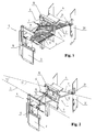
- FIG. 1 is a perspective view of a device 1 allowing the transfer of a strip material 2 between two media, namely between an external medium 4 to a machine 5 and an interior space or medium 6 to it, separated by one of the walls of the frame of the machine.
- this machine 5 or machine portion is only illustrated by some of its elements, in particular a first side wall 3 located on the driver's side and a second side wall 7 on the opposite conductor side.
- These walls forming the frame of a station generally called ejection station with reference to a platen press normally intended for cutting plate elements not shown.
- the scroll axis of these plate elements is represented in FIG. 2 by a mixed line corresponding to the longitudinal axis 8 of the machine.
- the direction of travel of the web material 2 from the outside medium 4 to the inner medium 6 of the machine is given by the arrow band 9 illustrated in FIG. 1 on the axis of travel of the web material 2.
- this path starts with a first, preferably horizontal, return roller 11, which allows the strip material to be supported at a level of use with respect to a window 10.
- This window is located at the interface of the two media 4 and 6, in the second side wall 7. It is through this window that will change the medium of the material strip 2.
- This window has a width L smaller than the width L b of the web material.
- the first return roller 11 is held in a frame 20 of a reel unwinder by means of brackets 21 attached against the walls of this frame.
- the orientation of the frame of this unwinder relative to the machine 5 is illustrated by a second mixed line corresponding to the axis of rotation 22 of the first return roller 11.
- the longitudinal axis 8 of the machine 5 and the axis of rotation 22 are preferably not parallel but are intercepted at an angle ⁇ corresponding to the orientation of the unwinder relative to the machine 5.
- the device 1 of the present invention then guides the web material 2 so that the transfer between the outer 4 and inner 6 environments is effected by at least one progressive reversal of this web material during its passage through the web. window 10.
- This reversal is defined here as being progressive since it starts in the external medium 4 and ends in the inner medium 6 or inversely according to the direction of travel of the material in band given by the arrow band 9.
- the web material is first turned on itself by a second deflection roll 12 so that the back of this web material comes over and is made visible.
- This second return roller passes through the window 10 and is fixed for one of its ends to the frame 20 of the unwinder on one of the brackets 21, and for the other end on the first side wall 3 of the frame of the machine by means of an angled plate 14.
- the end of the second return roller 12 attached to the frame 20 is fixed on the downstream wall of the unwinder frame and the opposite end is fixed on the first side wall 3 of the machine so that the second return roller 12 passes through the window 10 preferably near its downstream edge.
- the web material After passing around the second deflection roll 12, the web material is directed to a third return roll 13 to be turned a second time so that the back of this web material is again oriented downwardly as when it leaves the first return roller 11.
- This third return roller 13 also aims to redirect the strip material in the longitudinal axis 8 of the machine, within it.
- This third return roller is located downstream of the second return roller and is held by its ends between the side walls 3 and 7 inside the machine 5. More precisely, the third return roller is held in horizontal position at one of its ends by the bent plate 14, and at the other end by a bracket 16 secured to the second wall 7 and preferably located near the upstream edge of the window 10.
- the length of the third return roller is such that it allows to connect the walls 3 and 7 despite the non-perpendicular orientation of the roll with respect to the longitudinal axis of the machine.
- This arrangement of the second deflection roller 12 will determine the orientation of the axis of rotation 22 of the first return roller 11 and therefore the value of the angle ⁇ .
- the orientation of the first return roller 11 at a non-zero angle ⁇ causes compared to the machine 5 a particular arrangement of the unwinder which can be perceived as being inconvenient.
- the deflection angle of the third return roller 13 is determined by the condition for aligning the travel of the web material along the longitudinal axis 8 of the machine.
- first return roller 11 has a length at least equal to the maximum useful width of the machine 5, a width also called width in the jargon of those skilled in the art, and that the second and third rollers 12, 13 also cover the width of the machine despite their inclination relative to the longitudinal axis 8. With such a feature it becomes easy to locate on the first roller 11 return the boundary edges driver and driver opposite side corresponding to the maximum format of the material that can be passed to the machine.
- the arrangement provided in the device of the present invention also makes it possible to free up as much space as is necessary for the introduction of the strip material into the machine.
- the arrangement in the interior space 6 of the machine of only two return rollers 12, 13 it becomes possible not only to overcome the positioning and multiple adjustments that would require a plurality of rollers, each dedicated to the return of a strip, but also to rationalize the interior space 6 available by significantly reducing the number of pieces that is necessary to arrange.
- This aspect becomes particularly beneficial for places likely to be congested by the passage and stops of moving organs at fixed and predetermined locations.
- Such members can be typically clamp bars mounted transversely on a chain train and used to convey the plate elements in the different stations of the machine.
- the device 1 has been described for transferring a strip material from a medium 4 outside the machine 5, to a medium 6 located inside this machine.
- the reverse path could if necessary be perfectly obtained with the same device, by symmetry by simply returning the disposition of the different return rollers.
- web material it is meant to cover both the use of a single band, of large width for example, and a plurality of strips or strips placed next to one another with or without interstitial spaces.
- the second and third rolls of references 12, 13 are arranged in the same plane, preferably in the same horizontal plane.
- another arrangement of these rolls could also be considered depending on the path chosen for the web material.
- the transfer between the media 4 and 6 is carried out by less a gradual reversal of the material in strip 2 during its passage through the window 10, and that preferably, the strip material 2 is returned a first time around the second return roller 12, then at least a second time around at least one third return roller 13 so that this belt material can be machine-oriented parallel to the longitudinal axis 8.
- the second and third return rollers 12, 13 have upper generatrices situated in the same horizontal plane and preferably have different diameters, namely that the diameter of the second return roller 12 is smaller than that of the third roller. 13. Thanks to this feature, it is possible, on the one hand, to maintain the material strip horizontally at all times and, on the other hand, to benefit from a space separating the portion of material in strip located upstream of the second deflection roll 12 of that located downstream of the third deflection roll 13. This space thus makes it possible to avoid any friction between these two portions, which are thus no longer in the same plane .
Landscapes
- Engineering & Computer Science (AREA)
- Mechanical Engineering (AREA)
- Advancing Webs (AREA)
- Containers And Plastic Fillers For Packaging (AREA)
Claims (9)
- Transportvorrichtung (1) für ein Bandmaterial (2) zwischen einem äusserem Bereich (4) und einem inneren Bereich (6) einer Maschine (5) zur Behandlung des Bandmaterials (2), umfassend eine von einem Gestell einer Station gebildete Referenzlängsachse (8), wobei das Gestell eine erste seitliche Wandung (3) und eine zweite seitliche Wandung (7) umfasst, in der ein Fenster (10) ausgebildet ist, das an der Schnittstelle zwischen dem äusseren und dem inneren Bereich (4,6) angeordnet ist, ein zweites Gestell (20), das im äusseren Bereich (4) gegenüber dem Fenster (10) angeordnet ist und in dem eine erste Unterbandrolle (11) des Bandmaterials (2) eingerichtet ist, dadurch gekennzeichnet, dass sie eine zweite Unterbandrolle (12) dieses Bandmaterials umfasst, die durch das Fenster (10) hindurch angeordnet ist.
- Vorrichtung (1) nach Anspruch 1, dadurch gekennzeichnet, dass die zweite Unterbandrolle (12) derart eingerichtet ist, dass sie durch das Fenster (10) in der Nähe von dessen seitlichen Rand hindurchgeht.
- Vorrichtung (1) nach Anspruch 1, dadurch gekennzeichnet, dass sie wenigstens eine dritte Unterbandrolle (13) umfasst, welche zwischen der ersten seitlichen Wandung (3) und der zweiten seitlichen Wandung (7) eingerichtet ist.
- Vorrichtung (1) nach Anspruch 3, dadurch gekennzeichnet, dass die zweite und die dritte Unterbandrolle (12, 13) obere Aggregate aufweisen, die in einer gleichen horizontalen Ebene liegen.
- Vorrichtung (1) nach Anspruch 4, dadurch gekennzeichnet, dass die zweite Unterbandrolle (12) einen kleineren Durchmesser aufweist als die dritte Unterbandrolle (13).
- Vorrichtung (1) nach Anspruch 1, dadurch gekennzeichnet, dass die erste Unterbandrolle (11) bezüglich der Längsachse (8) der Maschine(5) in einer winkligen Position ausgerichtet ist, die einen Winkel (α) bestimmt, der nicht Null beträgt.
- Vorrichtung (1) nach Anspruch 1 oder 2, dadurch gekennzeichnet, dass die zweite Unterbandrolle (12) in einer zur Längsachse (8) der Maschine (5) orthogonalen Position ausgerichtet ist.
- Vorrichtung (1) nach Anspruch 3, dadurch gekennzeichnet, dass die dritte Unterbandrolle (13) zwischen der ersten und der zweiten Wandung (3, 7) entlang einem Winkel zur Rückausrichtung des Bandmaterials (2) in der Längsachse (8) der Maschine angeordnet ist.
- Vorrichtung (1) nach Anspruch 1, dadurch gekennzeichnet, dass wenigstens eine der Unterbandrollen (11, 12, 13) aus einem porösen Material hergestellt ist.
Priority Applications (4)
| Application Number | Priority Date | Filing Date | Title |
|---|---|---|---|
| ES04405250T ES2289468T3 (es) | 2004-04-23 | 2004-04-23 | Dispositivo de transferencia de un material en banda entre un medio exterior y un medio interior a una maquina. |
| AT04405250T ATE367991T1 (de) | 2004-04-23 | 2004-04-23 | Vorrichtung zur übertragung eines bahnförmigen materials zwischen einem äusseren und einem inneren medium einer maschine |
| EP04405250A EP1588969B1 (de) | 2004-04-23 | 2004-04-23 | Vorrichtung zur Übertragung eines bahnförmigen Materials zwischen einem äusseren und einem inneren Medium einer Maschine |
| DE602004007761T DE602004007761T2 (de) | 2004-04-23 | 2004-04-23 | Vorrichtung zur Übertragung eines bahnförmigen Materials zwischen einem äusseren und einem inneren Medium einer Maschine |
Applications Claiming Priority (1)
| Application Number | Priority Date | Filing Date | Title |
|---|---|---|---|
| EP04405250A EP1588969B1 (de) | 2004-04-23 | 2004-04-23 | Vorrichtung zur Übertragung eines bahnförmigen Materials zwischen einem äusseren und einem inneren Medium einer Maschine |
Publications (2)
| Publication Number | Publication Date |
|---|---|
| EP1588969A1 EP1588969A1 (de) | 2005-10-26 |
| EP1588969B1 true EP1588969B1 (de) | 2007-07-25 |
Family
ID=34932071
Family Applications (1)
| Application Number | Title | Priority Date | Filing Date |
|---|---|---|---|
| EP04405250A Expired - Lifetime EP1588969B1 (de) | 2004-04-23 | 2004-04-23 | Vorrichtung zur Übertragung eines bahnförmigen Materials zwischen einem äusseren und einem inneren Medium einer Maschine |
Country Status (4)
| Country | Link |
|---|---|
| EP (1) | EP1588969B1 (de) |
| AT (1) | ATE367991T1 (de) |
| DE (1) | DE602004007761T2 (de) |
| ES (1) | ES2289468T3 (de) |
Family Cites Families (5)
| Publication number | Priority date | Publication date | Assignee | Title |
|---|---|---|---|---|
| US5016801A (en) * | 1990-08-28 | 1991-05-21 | Industrial Label Corporation | Multiple-ply web registration apparatus |
| US5092573A (en) * | 1990-09-05 | 1992-03-03 | Abreu Michael L | Auxiliary paper feeding apparatus for high speed computer printers |
| EP0907513B1 (de) * | 1996-04-29 | 2002-07-24 | Koenig & Bauer Aktiengesellschaft | Wendestangenanordnung |
| DE19841171A1 (de) * | 1998-09-09 | 2000-05-25 | Koenig & Bauer Ag | Wendestangenanordnung |
| US6595465B2 (en) * | 2001-09-10 | 2003-07-22 | Energy Saving Products And Sales Corp. | Turn bar assembly for redirecting a continuous paper web |
-
2004
- 2004-04-23 AT AT04405250T patent/ATE367991T1/de not_active IP Right Cessation
- 2004-04-23 ES ES04405250T patent/ES2289468T3/es not_active Expired - Lifetime
- 2004-04-23 EP EP04405250A patent/EP1588969B1/de not_active Expired - Lifetime
- 2004-04-23 DE DE602004007761T patent/DE602004007761T2/de not_active Expired - Lifetime
Also Published As
| Publication number | Publication date |
|---|---|
| DE602004007761T2 (de) | 2008-03-06 |
| EP1588969A1 (de) | 2005-10-26 |
| DE602004007761D1 (de) | 2007-09-06 |
| ES2289468T3 (es) | 2008-02-01 |
| ATE367991T1 (de) | 2007-08-15 |
Similar Documents
| Publication | Publication Date | Title |
|---|---|---|
| EP0881173B1 (de) | Rollen- oder Bandförderer zum Transportieren und Drehen von Artikeln niedriger spezifischer Masse | |
| EP0056353B1 (de) | Maschine zum Schneiden, Falten und Fertigstellen von Bögen, ausgegeben aus aufgerollten Bahnen | |
| WO2010037475A1 (fr) | Dispositif de transport et de pliage de decoupes | |
| FR2620117A1 (fr) | Machines diviseuses et reenrouleuses de bande | |
| FR2548162A1 (fr) | Procede et appareil pour former et manipuler des piles de matiere en feuille | |
| EP3221242B1 (de) | Halterungssystem für eine bandspule zum stanzen, abrollmodul, stanzmaschine und einsetzverfahren der spule | |
| EP2834177B1 (de) | Antriebsvorrichtung für ein prägeband, abrollmodull und damit ausgerüstete prägemaschine | |
| EP2704973B1 (de) | Vorrichtung zum stapeln von papierbögen oder dergleichen | |
| FR2528023A1 (fr) | Procede et dispositif pour la reprise de produits plats se presentant en disposition en ecailles, en particulier pour la reprise de feuilles imprimees | |
| EP1136404B1 (de) | Vorrichtung zum longitudinalen Ausrichten von plattenförmigen Bauteilen in einer Zuführstation einer Maschine zu ihrer Bearbeitung | |
| EP2013125B1 (de) | Verfahren und anlage zur inspektion eines gewickelten bands | |
| FR3011823A1 (fr) | Machine d'ensachage de produits alimentaires et procede d'ensachage de produits alimentaires | |
| EP0741096B1 (de) | Transportvorrichtung für metallisiertes Bahnmaterial | |
| EP0574874A1 (de) | Vorrichtung zum Regeln des Abstands zwischen einem Klebestoffauftragszylinder und einem Bandzuführzylinder | |
| EP1588968B1 (de) | Trag- und Antriebsmodul eines aufgespulten bahnförmigen Materials für eine Bearbeitungsmaschine | |
| EP1588969A1 (de) | Vorrichtung zur Übertragung eines bahnförmigen Materials zwischen einem äusseren und einem inneren Medium einer Maschine | |
| CH689300A5 (fr) | Machine plieuse-colleuse incorporant un transporteur à rouleaux. | |
| EP1140680A1 (de) | Zuführvorrichtung für band aus weichem material an einer arbeitsstation | |
| FR2722181A1 (fr) | Plieuse. | |
| BE1009744A4 (fr) | Appareil de distribution automatique de matiere en feuille de conditionnement. | |
| EP0741095B1 (de) | Vorrichtung zum Laden von metallisiertem Bahnmaterial in eine Maschine zum Transfer von metallisierten Bildern auf flächige Elemente | |
| CH359593A (fr) | Dispositif permettant d'intercepter en cours de distribution des feuilles déposées une à une en pile | |
| FR3091863A1 (fr) | Installation et procédé automatiques de trancannage de bandelettes à partir d’une nappe présentée en bobine | |
| EP1588966B1 (de) | Vorrichtung zum Ausrichten von plattenförmigen Elementen in einer Maschine zu ihrer Bearbeitung | |
| EP3507222B1 (de) | Verfahren und anlage zur förderung eines spannungsarmen flexiblen bandes oder gurtes mit hoher geschwindigkeit |
Legal Events
| Date | Code | Title | Description |
|---|---|---|---|
| PUAI | Public reference made under article 153(3) epc to a published international application that has entered the european phase |
Free format text: ORIGINAL CODE: 0009012 |
|
| AK | Designated contracting states |
Kind code of ref document: A1 Designated state(s): AT BE BG CH CY CZ DE DK EE ES FI FR GB GR HU IE IT LI LU MC NL PL PT RO SE SI SK TR |
|
| AX | Request for extension of the european patent |
Extension state: AL HR LT LV MK |
|
| 17P | Request for examination filed |
Effective date: 20060203 |
|
| AKX | Designation fees paid |
Designated state(s): AT BE BG CH CY CZ DE DK EE ES FI FR GB GR HU IE IT LI LU MC NL PL PT RO SE SI SK TR |
|
| GRAP | Despatch of communication of intention to grant a patent |
Free format text: ORIGINAL CODE: EPIDOSNIGR1 |
|
| GRAS | Grant fee paid |
Free format text: ORIGINAL CODE: EPIDOSNIGR3 |
|
| GRAA | (expected) grant |
Free format text: ORIGINAL CODE: 0009210 |
|
| AK | Designated contracting states |
Kind code of ref document: B1 Designated state(s): AT BE BG CH CY CZ DE DK EE ES FI FR GB GR HU IE IT LI LU MC NL PL PT RO SE SI SK TR |
|
| REG | Reference to a national code |
Ref country code: GB Ref legal event code: FG4D Free format text: NOT ENGLISH |
|
| REG | Reference to a national code |
Ref country code: CH Ref legal event code: EP |
|
| REG | Reference to a national code |
Ref country code: IE Ref legal event code: FG4D Free format text: LANGUAGE OF EP DOCUMENT: FRENCH |
|
| REF | Corresponds to: |
Ref document number: 602004007761 Country of ref document: DE Date of ref document: 20070906 Kind code of ref document: P |
|
| GBT | Gb: translation of ep patent filed (gb section 77(6)(a)/1977) |
Effective date: 20070822 |
|
| PG25 | Lapsed in a contracting state [announced via postgrant information from national office to epo] |
Ref country code: FI Free format text: LAPSE BECAUSE OF FAILURE TO SUBMIT A TRANSLATION OF THE DESCRIPTION OR TO PAY THE FEE WITHIN THE PRESCRIBED TIME-LIMIT Effective date: 20070725 Ref country code: NL Free format text: LAPSE BECAUSE OF FAILURE TO SUBMIT A TRANSLATION OF THE DESCRIPTION OR TO PAY THE FEE WITHIN THE PRESCRIBED TIME-LIMIT Effective date: 20070725 Ref country code: PT Free format text: LAPSE BECAUSE OF FAILURE TO SUBMIT A TRANSLATION OF THE DESCRIPTION OR TO PAY THE FEE WITHIN THE PRESCRIBED TIME-LIMIT Effective date: 20071226 Ref country code: BG Free format text: LAPSE BECAUSE OF FAILURE TO SUBMIT A TRANSLATION OF THE DESCRIPTION OR TO PAY THE FEE WITHIN THE PRESCRIBED TIME-LIMIT Effective date: 20071025 |
|
| NLV1 | Nl: lapsed or annulled due to failure to fulfill the requirements of art. 29p and 29m of the patents act | ||
| REG | Reference to a national code |
Ref country code: ES Ref legal event code: FG2A Ref document number: 2289468 Country of ref document: ES Kind code of ref document: T3 |
|
| PG25 | Lapsed in a contracting state [announced via postgrant information from national office to epo] |
Ref country code: PL Free format text: LAPSE BECAUSE OF FAILURE TO SUBMIT A TRANSLATION OF THE DESCRIPTION OR TO PAY THE FEE WITHIN THE PRESCRIBED TIME-LIMIT Effective date: 20070725 Ref country code: AT Free format text: LAPSE BECAUSE OF FAILURE TO SUBMIT A TRANSLATION OF THE DESCRIPTION OR TO PAY THE FEE WITHIN THE PRESCRIBED TIME-LIMIT Effective date: 20070725 |
|
| REG | Reference to a national code |
Ref country code: IE Ref legal event code: FD4D |
|
| PG25 | Lapsed in a contracting state [announced via postgrant information from national office to epo] |
Ref country code: GR Free format text: LAPSE BECAUSE OF FAILURE TO SUBMIT A TRANSLATION OF THE DESCRIPTION OR TO PAY THE FEE WITHIN THE PRESCRIBED TIME-LIMIT Effective date: 20071026 Ref country code: DK Free format text: LAPSE BECAUSE OF FAILURE TO SUBMIT A TRANSLATION OF THE DESCRIPTION OR TO PAY THE FEE WITHIN THE PRESCRIBED TIME-LIMIT Effective date: 20070725 |
|
| PG25 | Lapsed in a contracting state [announced via postgrant information from national office to epo] |
Ref country code: SK Free format text: LAPSE BECAUSE OF FAILURE TO SUBMIT A TRANSLATION OF THE DESCRIPTION OR TO PAY THE FEE WITHIN THE PRESCRIBED TIME-LIMIT Effective date: 20070725 Ref country code: IE Free format text: LAPSE BECAUSE OF FAILURE TO SUBMIT A TRANSLATION OF THE DESCRIPTION OR TO PAY THE FEE WITHIN THE PRESCRIBED TIME-LIMIT Effective date: 20070725 Ref country code: CZ Free format text: LAPSE BECAUSE OF FAILURE TO SUBMIT A TRANSLATION OF THE DESCRIPTION OR TO PAY THE FEE WITHIN THE PRESCRIBED TIME-LIMIT Effective date: 20070725 |
|
| PLBE | No opposition filed within time limit |
Free format text: ORIGINAL CODE: 0009261 |
|
| STAA | Information on the status of an ep patent application or granted ep patent |
Free format text: STATUS: NO OPPOSITION FILED WITHIN TIME LIMIT |
|
| PG25 | Lapsed in a contracting state [announced via postgrant information from national office to epo] |
Ref country code: RO Free format text: LAPSE BECAUSE OF FAILURE TO SUBMIT A TRANSLATION OF THE DESCRIPTION OR TO PAY THE FEE WITHIN THE PRESCRIBED TIME-LIMIT Effective date: 20070725 Ref country code: SE Free format text: LAPSE BECAUSE OF FAILURE TO SUBMIT A TRANSLATION OF THE DESCRIPTION OR TO PAY THE FEE WITHIN THE PRESCRIBED TIME-LIMIT Effective date: 20071025 |
|
| 26N | No opposition filed |
Effective date: 20080428 |
|
| BERE | Be: lapsed |
Owner name: BOBST SA Effective date: 20080430 |
|
| PG25 | Lapsed in a contracting state [announced via postgrant information from national office to epo] |
Ref country code: MC Free format text: LAPSE BECAUSE OF NON-PAYMENT OF DUE FEES Effective date: 20080430 |
|
| PG25 | Lapsed in a contracting state [announced via postgrant information from national office to epo] |
Ref country code: EE Free format text: LAPSE BECAUSE OF FAILURE TO SUBMIT A TRANSLATION OF THE DESCRIPTION OR TO PAY THE FEE WITHIN THE PRESCRIBED TIME-LIMIT Effective date: 20070725 |
|
| PG25 | Lapsed in a contracting state [announced via postgrant information from national office to epo] |
Ref country code: BE Free format text: LAPSE BECAUSE OF NON-PAYMENT OF DUE FEES Effective date: 20080430 |
|
| PG25 | Lapsed in a contracting state [announced via postgrant information from national office to epo] |
Ref country code: SI Free format text: LAPSE BECAUSE OF FAILURE TO SUBMIT A TRANSLATION OF THE DESCRIPTION OR TO PAY THE FEE WITHIN THE PRESCRIBED TIME-LIMIT Effective date: 20070725 |
|
| PG25 | Lapsed in a contracting state [announced via postgrant information from national office to epo] |
Ref country code: CY Free format text: LAPSE BECAUSE OF FAILURE TO SUBMIT A TRANSLATION OF THE DESCRIPTION OR TO PAY THE FEE WITHIN THE PRESCRIBED TIME-LIMIT Effective date: 20070725 |
|
| PG25 | Lapsed in a contracting state [announced via postgrant information from national office to epo] |
Ref country code: LU Free format text: LAPSE BECAUSE OF NON-PAYMENT OF DUE FEES Effective date: 20080423 Ref country code: HU Free format text: LAPSE BECAUSE OF FAILURE TO SUBMIT A TRANSLATION OF THE DESCRIPTION OR TO PAY THE FEE WITHIN THE PRESCRIBED TIME-LIMIT Effective date: 20080126 |
|
| PG25 | Lapsed in a contracting state [announced via postgrant information from national office to epo] |
Ref country code: TR Free format text: LAPSE BECAUSE OF FAILURE TO SUBMIT A TRANSLATION OF THE DESCRIPTION OR TO PAY THE FEE WITHIN THE PRESCRIBED TIME-LIMIT Effective date: 20070725 |
|
| REG | Reference to a national code |
Ref country code: FR Ref legal event code: PLFP Year of fee payment: 13 |
|
| REG | Reference to a national code |
Ref country code: FR Ref legal event code: PLFP Year of fee payment: 14 |
|
| REG | Reference to a national code |
Ref country code: FR Ref legal event code: PLFP Year of fee payment: 15 |
|
| PGFP | Annual fee paid to national office [announced via postgrant information from national office to epo] |
Ref country code: IT Payment date: 20230310 Year of fee payment: 20 Ref country code: GB Payment date: 20230302 Year of fee payment: 20 |
|
| PGFP | Annual fee paid to national office [announced via postgrant information from national office to epo] |
Ref country code: FR Payment date: 20230405 Year of fee payment: 20 Ref country code: ES Payment date: 20230510 Year of fee payment: 20 Ref country code: DE Payment date: 20230307 Year of fee payment: 20 Ref country code: CH Payment date: 20230502 Year of fee payment: 20 |
|
| REG | Reference to a national code |
Ref country code: DE Ref legal event code: R071 Ref document number: 602004007761 Country of ref document: DE |
|
| REG | Reference to a national code |
Ref country code: CH Ref legal event code: PL Ref country code: ES Ref legal event code: FD2A Effective date: 20240430 |
|
| REG | Reference to a national code |
Ref country code: GB Ref legal event code: PE20 Expiry date: 20240422 |
|
| PG25 | Lapsed in a contracting state [announced via postgrant information from national office to epo] |
Ref country code: GB Free format text: LAPSE BECAUSE OF EXPIRATION OF PROTECTION Effective date: 20240422 |
|
| PG25 | Lapsed in a contracting state [announced via postgrant information from national office to epo] |
Ref country code: ES Free format text: LAPSE BECAUSE OF EXPIRATION OF PROTECTION Effective date: 20240424 |
|
| PG25 | Lapsed in a contracting state [announced via postgrant information from national office to epo] |
Ref country code: GB Free format text: LAPSE BECAUSE OF EXPIRATION OF PROTECTION Effective date: 20240422 Ref country code: ES Free format text: LAPSE BECAUSE OF EXPIRATION OF PROTECTION Effective date: 20240424 |