EP1588968B1 - Trag- und Antriebsmodul eines aufgespulten bahnförmigen Materials für eine Bearbeitungsmaschine - Google Patents
Trag- und Antriebsmodul eines aufgespulten bahnförmigen Materials für eine Bearbeitungsmaschine Download PDFInfo
- Publication number
- EP1588968B1 EP1588968B1 EP04405253A EP04405253A EP1588968B1 EP 1588968 B1 EP1588968 B1 EP 1588968B1 EP 04405253 A EP04405253 A EP 04405253A EP 04405253 A EP04405253 A EP 04405253A EP 1588968 B1 EP1588968 B1 EP 1588968B1
- Authority
- EP
- European Patent Office
- Prior art keywords
- module
- reel
- drive
- machine
- walls
- Prior art date
- Legal status (The legal status is an assumption and is not a legal conclusion. Google has not performed a legal analysis and makes no representation as to the accuracy of the status listed.)
- Expired - Lifetime
Links
- 238000012545 processing Methods 0.000 title claims description 6
- 239000000463 material Substances 0.000 title description 18
- 230000009471 action Effects 0.000 claims description 2
- 239000011888 foil Substances 0.000 claims 6
- 238000005520 cutting process Methods 0.000 description 13
- 230000008901 benefit Effects 0.000 description 4
- 238000004519 manufacturing process Methods 0.000 description 4
- 239000000969 carrier Substances 0.000 description 3
- 230000009466 transformation Effects 0.000 description 3
- 230000006978 adaptation Effects 0.000 description 2
- 230000007246 mechanism Effects 0.000 description 2
- 239000002184 metal Substances 0.000 description 2
- 238000004806 packaging method and process Methods 0.000 description 2
- 239000000123 paper Substances 0.000 description 2
- 238000002360 preparation method Methods 0.000 description 2
- 239000000758 substrate Substances 0.000 description 2
- 238000012549 training Methods 0.000 description 2
- 238000012546 transfer Methods 0.000 description 2
- 239000002699 waste material Substances 0.000 description 2
- 241000287828 Gallus gallus Species 0.000 description 1
- 230000008859 change Effects 0.000 description 1
- 235000013330 chicken meat Nutrition 0.000 description 1
- 230000008878 coupling Effects 0.000 description 1
- 238000010168 coupling process Methods 0.000 description 1
- 238000005859 coupling reaction Methods 0.000 description 1
- 230000001186 cumulative effect Effects 0.000 description 1
- 230000003247 decreasing effect Effects 0.000 description 1
- 238000000151 deposition Methods 0.000 description 1
- 238000001514 detection method Methods 0.000 description 1
- 238000006073 displacement reaction Methods 0.000 description 1
- 230000000694 effects Effects 0.000 description 1
- 238000004049 embossing Methods 0.000 description 1
- 238000012423 maintenance Methods 0.000 description 1
- 238000000034 method Methods 0.000 description 1
- 230000004048 modification Effects 0.000 description 1
- 238000012986 modification Methods 0.000 description 1
- 230000003287 optical effect Effects 0.000 description 1
- 210000000056 organ Anatomy 0.000 description 1
- 230000000737 periodic effect Effects 0.000 description 1
- 230000008569 process Effects 0.000 description 1
- 230000002441 reversible effect Effects 0.000 description 1
- 125000006850 spacer group Chemical group 0.000 description 1
- 238000004804 winding Methods 0.000 description 1
Images

Classifications
-
- B—PERFORMING OPERATIONS; TRANSPORTING
- B65—CONVEYING; PACKING; STORING; HANDLING THIN OR FILAMENTARY MATERIAL
- B65H—HANDLING THIN OR FILAMENTARY MATERIAL, e.g. SHEETS, WEBS, CABLES
- B65H16/00—Unwinding, paying-out webs
- B65H16/10—Arrangements for effecting positive rotation of web roll
- B65H16/106—Arrangements for effecting positive rotation of web roll in which power is applied to web roll
-
- B—PERFORMING OPERATIONS; TRANSPORTING
- B65—CONVEYING; PACKING; STORING; HANDLING THIN OR FILAMENTARY MATERIAL
- B65H—HANDLING THIN OR FILAMENTARY MATERIAL, e.g. SHEETS, WEBS, CABLES
- B65H16/00—Unwinding, paying-out webs
- B65H16/02—Supporting web roll
- B65H16/021—Multiple web roll supports
-
- B—PERFORMING OPERATIONS; TRANSPORTING
- B65—CONVEYING; PACKING; STORING; HANDLING THIN OR FILAMENTARY MATERIAL
- B65H—HANDLING THIN OR FILAMENTARY MATERIAL, e.g. SHEETS, WEBS, CABLES
- B65H2301/00—Handling processes for sheets or webs
- B65H2301/40—Type of handling process
- B65H2301/44—Moving, forwarding, guiding material
- B65H2301/443—Moving, forwarding, guiding material by acting on surface of handled material
- B65H2301/4432—Moving, forwarding, guiding material by acting on surface of handled material by means having an operating surface contacting only one face of the material, e.g. roller
- B65H2301/44322—Moving, forwarding, guiding material by acting on surface of handled material by means having an operating surface contacting only one face of the material, e.g. roller belt
-
- B—PERFORMING OPERATIONS; TRANSPORTING
- B65—CONVEYING; PACKING; STORING; HANDLING THIN OR FILAMENTARY MATERIAL
- B65H—HANDLING THIN OR FILAMENTARY MATERIAL, e.g. SHEETS, WEBS, CABLES
- B65H2301/00—Handling processes for sheets or webs
- B65H2301/50—Auxiliary process performed during handling process
- B65H2301/51—Modifying a characteristic of handled material
- B65H2301/512—Changing form of handled material
- B65H2301/5126—Embossing, crimping or similar processes
-
- B—PERFORMING OPERATIONS; TRANSPORTING
- B65—CONVEYING; PACKING; STORING; HANDLING THIN OR FILAMENTARY MATERIAL
- B65H—HANDLING THIN OR FILAMENTARY MATERIAL, e.g. SHEETS, WEBS, CABLES
- B65H2403/00—Power transmission; Driving means
- B65H2403/20—Belt drives
-
- B—PERFORMING OPERATIONS; TRANSPORTING
- B65—CONVEYING; PACKING; STORING; HANDLING THIN OR FILAMENTARY MATERIAL
- B65H—HANDLING THIN OR FILAMENTARY MATERIAL, e.g. SHEETS, WEBS, CABLES
- B65H2801/00—Application field
- B65H2801/81—Packaging machines
Definitions
- the present invention relates to a module for supporting and driving a wound strip material for a machine working, especially for a machine for the use of metallized strips for the manufacture of packaging.
- Such a machine is used for the embossing and pressure transfer of portions of films, preferably metal, from such strips on a substrate of paper, plastic or cardboard more particularly.
- These operations are for example carried out in a machine equipped with a platen press working plate elements, such as cardboard sheets, for the stamping of given patterns.
- These patterns are derived from a metallized strip conducted between the scroll plane of the plate elements and the upper bed of the press.
- the movable lower bed base will press the metallized strip against each sheet of cardboard between shots and corresponding counterparts to deposit the gilding in correspondence with the patterns of the pictures.
- the lower bed base descends and the stamped cardboard sheet is removed from the platen press to make room for a new sheet.
- the metallized strip is moved so that a new virgin surface is mapped to the plates. The process of cutting and transferring the tape can then be repeated.
- Such a machine can also be used for cutting cardboard sheets according to a sequence of operations each made in an adjacent station.
- This series of operations usually includes the introduction of the sheet in the press, its cutting by tools arranged on the plate, the ejection of waste by specific tools and the receipt in stacks of cut sheet elements.
- it is known to be able to transform it so that the station initially intended for cutting becomes a stamping station for metallized strips by replacing the cutting tools in a device for cutting. stamping and replacing the tools of the ejection station in a device for loading and unwinding the metallized strip coils.
- stamping and replacing the tools of the ejection station in a device for loading and unwinding the metallized strip coils.
- Such a transformation is illustrated by the machine described in the patent EP 741,096 .
- the assembly formed by the device for loading and supporting the coils, the return rollers, the drive rollers, their motorization and the pressure rollers adjustable in position requires the implementation of substantial work when it s is to arrange such a device in a cutting machine for its transformation into a stamping machine. Since they can not be made in masked time, these processing works immobilize the machine for long hours and contribute to the increase of the future production, mainly during small series.
- the majority of the gilding deposited on the packages can be made from strips of small width, generally not exceeding 30 cm, it is sometimes necessary to use metallized strips of greater width, typically of the order of 50 to 70 cm, or a plurality of narrower bands arranged side by side and whose total cumulative width is around this order of magnitude.
- the document US 4,341,586 discloses a strip material dispensing device for packaging large rolls of paper to protect them prior to use.
- the strip material for this package is wound on coils disposed between the walls of two adjacent frames. These coils are carried by their hub on shafts which are supported at their ends directly between the walls of the corresponding frame.
- the arrangement for example of three coils on such a shaft does not allow the removal of the central coil without the prior removal of one of the side coils.
- the object of the present invention is to remedy, at least in part, the aforementioned drawbacks by suggesting a new support module and drive a strip material for a machine working.
- the object of the present invention is to provide optimum access for loading and unloading coils, even large ones, by any conventional means.
- the handling of such reels should not be limited or made impossible by a nearby restricted space or by an impossible access route.
- the object of the present invention must also allow its preparation in masked time to reduce as much as possible the downtime of the machine during processing. He must offer a fast and user-friendly convertibility of the cutting machine into a stamping machine and vice versa.
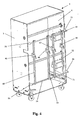
- the figure 1 shows the object of the present invention, seen from the front, which consists of a module 1, independent, located entirely outside an adjacent machine not shown that works a material band. It is therefore expected that this module is disposed out of this machine and out of its longitudinal axis, preferably at the height of the ejection station normally provided in any cutting machine performance. This station has been converted for the occasion into an arranged space of rollers of references arranged for example at 45 ° with respect to the longitudinal axis of the machine. Therefore, it is expected that the strip or strips from this module 1 can enter said machine by its side, through an open window in one of the side walls of its frame, before being deflected by said reference rolls in registration with the longitudinal axis of this machine.
- the module 1 comprises a frame formed of a base 2 and two side walls 3, 4 constituting a bearing structure 5, in particular for a plurality of coils 6 from which said strip material originates. Each coil is supported by a reel holder 10 and is rotated by at least one driving device 20.
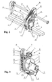
- FIGS. figures 1 and 2 show in more detail, from the rear, one of the drive members 20 and the spool holder 10 associated with this device.
- This spool holder consists of two flanges 11 which support the spool 6 by its hub 7.
- This spool is mounted free to rotate by means of flanges 11, each arranged on a support 12.
- These supports are in turn fixed on a reel bar 15 by means of clamping member 13, such as knurled screws or chickens for example.
- the reel carriers 10 are adjustable along the bar 15 which, as illustrated in FIGS. figures 1 and 2 , is preferably of square section and is supported at its ends by the walls 3 and 4 of the supporting structure 5. With such reel carriers 10 removable independently of each other, it is possible to adjust, place and easily remove a coil 6 from module 1 without having to move other coils already in place.
- the driving device 20 comprises two cheeks 21, 22 between which turns a belt 16, endless, better visible in the figure 3 .
- This belt is arranged so that it is always in contact with a rear portion of the outer circumference of the coil 6. By friction with this cylindrical portion, the coil is rotated by the action of the belt 16 and of therefore, the web material may be unwound for use in an adjoining machine, or even rolled back if it comes from this machine.
- the cheeks 21, 22 are held together by spacers 23 and allow in particular the arrangement of a drive member 24 for the rotation of the belt 16.
- the belt respectively runs around a tensioning roller 25, then around a plurality of return rollers 26 including a lower return roller 27 located at the lower end of the path slightly below the coil 6, before going up to the body d 24 when the strip material is unwound from the coil, the diameter of the latter decreasing, the length of the path of the belt between the lower return roller 27 and the drive member 24 is constantly varied.
- the purpose of the tensioning roller is to compensate for these variations at any time. To do this, it is slidably mounted along an oblong opening 28 and is connected to a tensioning mechanism 30.
- This mechanism can be provided with an elastic means, such as a tension spring 31 for example, connected to the tensioner roller 25 by a rope 32.
- the drive device 20 adjustable between the walls 3, 4 of the supporting structure 5, is held in abutment at one of its ends on a support bar 29 and at the other end by means of the driving member 24.
- the support bar 29 is held stationary between the walls of the supporting structure 5.
- the drive member 24 is preferably constituted by a ring traversed by a feed shaft 40. This shaft of advance is also maintained between the side walls 3, 4 of the module 1 and is connected at one of its ends to an electric motor 41 by a feed belt 42. It is this engine electrical drive that will be able to drive the adjacent drive device or 20 associated with the same feed shaft 40, through the corresponding drive members 24.
- the supporting structure 5 is mounted on rollers 8 to increase the mobility of the module 1 and to authorize if necessary its displacement in a clear space, free of any bulk.
- the module of the present invention is provided with a plurality of coils 6 distributed over two stages. However, it will be noted that another arrangement of these coils, on one or several stages, could also be adopted.
- the number of coil drive devices can vary at will, depending on the width of the strip, its unwound length, its diameter or the drive rate, for example.
- the drive performance of the coils can be significantly increased by using multiple drive devices to drive the coils.
- the coupling of several devices on the same coil also makes it possible to better control the effect of inertia that can produce this coil when it is rotated and thus also authorizes faster speeds of advance.
- the coils 6 which are arranged on the same feed shaft 40 are driven simultaneously by the same motor 41.
- Another embodiment would be to provide some or all of the drive devices 20 with an electric motor 41 specific to each belt 16.
- each drive member 24 of each drive device 20 could be driven by an engine independent electric 41, which is for example directly embedded on the drive device itself. Such an arrangement would then drive in a differentiated manner the unwinding of the coils concerned to be able to benefit from different speeds and rates according to the specific needs of these coils.
- the use of handling means such as pallet trucks, elevators or hoists, for example, can be advantageously used for the loading / unloading of heavy coils without fear that access is limited, difficult or impossible.
- the clearance available around the module of the present invention thus offers perspectives technical and ergonomic unthinkable previously with a module confined inside the machine working the material band.
- the concept of a unit external to the machine makes it possible to multiply the possibilities that such a module can offer with respect to a device for loading coils installed within the machine.
- the diameter of the reels of the strip material or the number of bearing shafts of these reels is not limited by a finite volume, determined by the space available in the machine between the walls of its frame.
- it would be desirable for such an arrangement to be able to take place at the bottom of the module, closest to the ground so that, for example, the lifting stroke of a pallet truck is sufficient to put the coil in place more easily. question.
- the drive of the coils as provided in the module of the present invention requires no adjustment during production. This is not usually the case in current systems that use mechanical brakes to control the inertia of the coils at each gear change.
- the module of the present invention is fully accessible for both preparation work for a future work for maintenance operations.
- the reading and the marking of the connections and the holographic patterns of the diffraction-effect strips necessitates an adjustment run of the optical cells 45 to 48 which are much larger than in the case of reading. only positions of holographic patterns.
- the reading cells 45 to 48 are arranged so as to slide respectively along the vertical bars 49, 50, 51, 52.
- the vertical bars 49 to 52 are mounted, so that they can slide laterally on two crosspieces 53, 54 carried by supports 55 and 56 fixed to the walls 3 and 4 of the supporting structure 5.
- the external module can advantageously serve as a support for this kind of ancillary devices without being restricted to a limited surrounding space.
- the module as described is preferably used as an unwinder module for transferring a material strip from this module to a machine working.
- the reverse path could, if necessary, be perfectly obtained with the same module by simply reversing its initial unwinding module function in a retractor module for used web material for example.
- web material it is meant to cover both the use of a single band, of large width for example, and a plurality of strips or strips placed next to one another with or without interstitial spaces.
- machine in which the device of the present invention has been described clearly refers to a platen press working plate elements, it will be mentioned that the use of this device is not limited to such machines.
Landscapes
- Unwinding Webs (AREA)
- Replacement Of Web Rolls (AREA)
- Advancing Webs (AREA)
- Registering, Tensioning, Guiding Webs, And Rollers Therefor (AREA)
- Preliminary Treatment Of Fibers (AREA)
Claims (8)
- Modul (1) zum Haltern und Antreiben eines aufgewickelten Bandmaterials für eine Maschine zum Verarbeiten dieses Material, welches eine Haltestruktur (5) einschließt, die sich außerhalb der Verarbeitungsmaschine befindet und zwei Seitenwände (3, 4) einschließt, zwischen welchen eine Mehrzahl von Rollenhaltern (10) für wenigstens eine freidrehbar montierte Rolle (6) angeordnet ist, wobei die Rollenhalter (10) mit wenigstens einer Antriebsvorrichtung (20) zum Abwickeln des Bandmaterials der Rolle (6) verbunden sind,
dadurch gekennzeichnet, dass zwischen den Seitenwänden (3, 4) wenigstens eine Halterungsstange (15) der Rollenhalter (10) angeordnet ist und dass die Rollenhalter (10) voneinander unabhängig bewegbar sind und sie entlang wenigstens einer zwischen den Wänden (3, 4) der Haltestruktur (5) gehaltenen Stange (15) einstellbar sind. - Modul (1) gemäß Anspruch 1, dadurch gekennzeichnet, dass die Antriebsvorrichtung (20) zwischen den Wänden (3, 4) der Haltestruktur (5) seitlich einstellbar ist und dass es einen Riemen (16) zum Drehantreiben der Rolle (6) des Rollenhalters (10) einschließt, der diesem mittels eines von einem Elektromotor (41) gesteuerten Antriebsorgans (24) zugeordnet ist.
- Modul (1) gemäß Anspruch 2, dadurch gekennzeichnet, dass die Antriebsorgane (24) mehrerer benachbarter Antriebsvorrichtungen (20) vom gleichen Elektromotor (41) gesteuert sind, und zwar mittels einer Vortriebswelle (40), welche die Antriebsorgane (24) miteinander verbindet.
- Modul (1) gemäß Anspruch 3, dadurch gekennzeichnet, dass mehrere Vortriebswellen (40) untereinander verbunden sind, um die auf die Rollen (6) übertragene, mechanische Antriebskraft zu vergrößern.
- Modul (1) gemäß Anspruch 3, dadurch gekennzeichnet, dass jedes Antriebsorgan (24) jeder Antriebsvorrichtung (20) von einem unabhängigen Elektromotor (41) gesteuert ist.
- Modul (1) gemäß Anspruch 2, dadurch gekennzeichnet, dass der Riemen (16) mit einem Umfangsabschnitt der Rolle (6) in Kontakt tritt und dass dieser Riemen (16) durch die Wirkung einer in der Antriebsvorrichtung (20) angeordneten Spannrolle (25) dauerhaft gespannt ist.
- Modul (1) gemäß Anspruch 1, dadurch gekennzeichnet, dass die Haltestruktur (5) mit Laufrollen (8) versehen ist.
- Modul (1) gemäß Anspruch 1, dadurch gekennzeichnet, dass es wenigstens ein zusätzliches Organ zum Verarbeiten des Bandmaterials einschließt, welches von spezifischen Lesezellen (45, 46, 47, 48) gebildet ist, um Motive oder Anschlüsse bestimmter Bänder, wie beispielsweise Hologrammbänder oder Bänder mit Brechungswirkung, zu detektieren, wobei die Lesezellen (45 bis 48) derart angeordnet sind, dass sie jeweils entlang von Vertikalstangen (49, 50, 51, 52) verschiebbar sind, die derart montiert sind, dass sie ebenfalls seitlich verschiebbar sind, und zwar auf zwei Traversen (53, 54), die von Halterungen (55, 56) gehalten sind, die an den Wänden (3, 4) der Haltestruktur (5) befestigt sind.
Priority Applications (4)
| Application Number | Priority Date | Filing Date | Title |
|---|---|---|---|
| DE602004027886T DE602004027886D1 (de) | 2004-04-23 | 2004-04-23 | Trag- und Antriebsmodul eines aufgespulten bahnförmigen Materials für eine Bearbeitungsmaschine |
| EP04405253A EP1588968B1 (de) | 2004-04-23 | 2004-04-23 | Trag- und Antriebsmodul eines aufgespulten bahnförmigen Materials für eine Bearbeitungsmaschine |
| ES04405253T ES2347785T3 (es) | 2004-04-23 | 2004-04-23 | Modulo de soporte y de arrastre de un material de banda bobinado por una maquina que lo procesa. |
| AT04405253T ATE472501T1 (de) | 2004-04-23 | 2004-04-23 | Trag- und antriebsmodul eines aufgespulten bahnförmigen materials für eine bearbeitungsmaschine |
Applications Claiming Priority (1)
| Application Number | Priority Date | Filing Date | Title |
|---|---|---|---|
| EP04405253A EP1588968B1 (de) | 2004-04-23 | 2004-04-23 | Trag- und Antriebsmodul eines aufgespulten bahnförmigen Materials für eine Bearbeitungsmaschine |
Publications (2)
| Publication Number | Publication Date |
|---|---|
| EP1588968A1 EP1588968A1 (de) | 2005-10-26 |
| EP1588968B1 true EP1588968B1 (de) | 2010-06-30 |
Family
ID=34932073
Family Applications (1)
| Application Number | Title | Priority Date | Filing Date |
|---|---|---|---|
| EP04405253A Expired - Lifetime EP1588968B1 (de) | 2004-04-23 | 2004-04-23 | Trag- und Antriebsmodul eines aufgespulten bahnförmigen Materials für eine Bearbeitungsmaschine |
Country Status (4)
| Country | Link |
|---|---|
| EP (1) | EP1588968B1 (de) |
| AT (1) | ATE472501T1 (de) |
| DE (1) | DE602004027886D1 (de) |
| ES (1) | ES2347785T3 (de) |
Families Citing this family (5)
| Publication number | Priority date | Publication date | Assignee | Title |
|---|---|---|---|---|
| TWI283650B (en) | 2004-04-23 | 2007-07-11 | Bobst Sa | Module for supporting and driving a wound foil matter for a machine processing it |
| JP6306567B2 (ja) | 2012-04-04 | 2018-04-04 | ボブスト メックス ソシエテ アノニム | 押箔のための駆動装置、並びにこれを装備した繰り出しモジュール及び箔押機械 |
| JP6405464B2 (ja) * | 2014-11-21 | 2018-10-17 | ボブスト メックス ソシエテ アノニム | スタンピングホイル用リールを支持するシステム、巻き戻しモジュール、スタンピング機械、及びリールを位置決めするための方法 |
| EP3368315B1 (de) | 2015-10-28 | 2020-08-12 | Bobst Mex Sa | Montagevorrichtung einer prägefolienspule, trägermodul, prägepresse und verfahren zum laden und entladen einer prägefolienspule |
| TWI718698B (zh) * | 2018-10-29 | 2021-02-11 | 瑞士商巴柏斯特麥克斯合資公司 | 全像箔供給裝置以及燙金印刷機 |
Family Cites Families (4)
| Publication number | Priority date | Publication date | Assignee | Title |
|---|---|---|---|---|
| US1410825A (en) * | 1920-10-19 | 1922-03-28 | Mascord George William | Apparatus for feeding web reels or rolls in rotary newspaper printing and similar machines |
| US3823934A (en) * | 1971-11-03 | 1974-07-16 | Standard Register Co | Production of multiple-copy business forms |
| FI58465C (fi) * | 1979-10-19 | 1981-02-10 | Waertsilae Oy Ab | System foer frammatning av foerpackningsomslag pao stora pappersrullar |
| NL8200980A (nl) * | 1982-03-10 | 1983-10-03 | Oce Nederland Bv | Rollenhouder met snijinrichting. |
-
2004
- 2004-04-23 EP EP04405253A patent/EP1588968B1/de not_active Expired - Lifetime
- 2004-04-23 ES ES04405253T patent/ES2347785T3/es not_active Expired - Lifetime
- 2004-04-23 DE DE602004027886T patent/DE602004027886D1/de not_active Expired - Lifetime
- 2004-04-23 AT AT04405253T patent/ATE472501T1/de not_active IP Right Cessation
Also Published As
| Publication number | Publication date |
|---|---|
| ES2347785T3 (es) | 2010-11-04 |
| ATE472501T1 (de) | 2010-07-15 |
| DE602004027886D1 (de) | 2010-08-12 |
| EP1588968A1 (de) | 2005-10-26 |
Similar Documents
| Publication | Publication Date | Title |
|---|---|---|
| EP0881173B1 (de) | Rollen- oder Bandförderer zum Transportieren und Drehen von Artikeln niedriger spezifischer Masse | |
| FR2566754A1 (fr) | Machine pour enrouler des bandes ou des feuilles sur une ame | |
| BE1001272A3 (fr) | Machines a diviser et a rebobiner des bandes. | |
| EP2834177B1 (de) | Antriebsvorrichtung für ein prägeband, abrollmodull und damit ausgerüstete prägemaschine | |
| FR2548162A1 (fr) | Procede et appareil pour former et manipuler des piles de matiere en feuille | |
| FR2619557A1 (fr) | Dispositif de sortie pour textile en bande | |
| EP3221242B1 (de) | Halterungssystem für eine bandspule zum stanzen, abrollmodul, stanzmaschine und einsetzverfahren der spule | |
| EP1588968B1 (de) | Trag- und Antriebsmodul eines aufgespulten bahnförmigen Materials für eine Bearbeitungsmaschine | |
| EP0638496A1 (de) | Vorrichtung und Verfahren zum Einführen von blattformigem Material in eine Maschine | |
| FR2528023A1 (fr) | Procede et dispositif pour la reprise de produits plats se presentant en disposition en ecailles, en particulier pour la reprise de feuilles imprimees | |
| EP2704973B1 (de) | Vorrichtung zum stapeln von papierbögen oder dergleichen | |
| EP2138305B1 (de) | Druckmaschine | |
| EP1335480B1 (de) | Verfahren und Vorrichtung zur Herstellung eines magnetischen Kreises einer elektrischen Maschine | |
| EP0742170B1 (de) | Vorrichtung zum Zuführen einer kontinuierlich ankommenden Bahn in einer Station, die sie in angehaltenem Zustand bearbeitet | |
| EP3810537B1 (de) | Band-abrollvorrichtung und maschine zum stanzen von elementen in form von blättern | |
| WO2019008480A1 (fr) | Dispositif de support simultané de plusieurs rouleaux de matière imprimable | |
| EP0156738A1 (de) | Vorrichtung zum Aufwickeln eines Stoffes während der verschiedenen Herstellungsphasen | |
| LU83240A1 (fr) | Machine de soudage de feuilles thermoplastiques enroulees | |
| FR2690681A1 (fr) | Dispositif pour enrouler ou pour enrouler dérouler du câble sur touret. | |
| FR2484975A1 (fr) | Dispositif d'alimentation pour machines de pliage | |
| BE889349A (fr) | Procede et appareil d'assemblage de matiere en feuille, notamment pour alimenter en continu des imprimantes rapides | |
| EP0741095B1 (de) | Vorrichtung zum Laden von metallisiertem Bahnmaterial in eine Maschine zum Transfer von metallisierten Bildern auf flächige Elemente | |
| EP1588969B1 (de) | Vorrichtung zur Übertragung eines bahnförmigen Materials zwischen einem äusseren und einem inneren Medium einer Maschine | |
| CH689300A5 (fr) | Machine plieuse-colleuse incorporant un transporteur à rouleaux. | |
| FR2807394A1 (fr) | Derouleur/enrouleur pour bande-support d'etiquettes adhesives ou objets similaires |
Legal Events
| Date | Code | Title | Description |
|---|---|---|---|
| PUAI | Public reference made under article 153(3) epc to a published international application that has entered the european phase |
Free format text: ORIGINAL CODE: 0009012 |
|
| AK | Designated contracting states |
Kind code of ref document: A1 Designated state(s): AT BE BG CH CY CZ DE DK EE ES FI FR GB GR HU IE IT LI LU MC NL PL PT RO SE SI SK TR |
|
| AX | Request for extension of the european patent |
Extension state: AL HR LT LV MK |
|
| 17P | Request for examination filed |
Effective date: 20060221 |
|
| AKX | Designation fees paid |
Designated state(s): AT BE BG CH CY CZ DE DK EE ES FI FR GB GR HU IE IT LI LU MC NL PL PT RO SE SI SK TR |
|
| 17Q | First examination report despatched |
Effective date: 20060411 |
|
| GRAP | Despatch of communication of intention to grant a patent |
Free format text: ORIGINAL CODE: EPIDOSNIGR1 |
|
| GRAS | Grant fee paid |
Free format text: ORIGINAL CODE: EPIDOSNIGR3 |
|
| GRAA | (expected) grant |
Free format text: ORIGINAL CODE: 0009210 |
|
| GRAL | Information related to payment of fee for publishing/printing deleted |
Free format text: ORIGINAL CODE: EPIDOSDIGR3 |
|
| GRAS | Grant fee paid |
Free format text: ORIGINAL CODE: EPIDOSNIGR3 |
|
| AK | Designated contracting states |
Kind code of ref document: B1 Designated state(s): AT BE BG CH CY CZ DE DK EE ES FI FR GB GR HU IE IT LI LU MC NL PL PT RO SE SI SK TR |
|
| REG | Reference to a national code |
Ref country code: GB Ref legal event code: FG4D Free format text: NOT ENGLISH Ref country code: CH Ref legal event code: EP |
|
| REG | Reference to a national code |
Ref country code: IE Ref legal event code: FG4D Free format text: LANGUAGE OF EP DOCUMENT: FRENCH |
|
| REF | Corresponds to: |
Ref document number: 602004027886 Country of ref document: DE Date of ref document: 20100812 Kind code of ref document: P |
|
| REG | Reference to a national code |
Ref country code: NL Ref legal event code: T3 |
|
| PG25 | Lapsed in a contracting state [announced via postgrant information from national office to epo] |
Ref country code: SE Free format text: LAPSE BECAUSE OF FAILURE TO SUBMIT A TRANSLATION OF THE DESCRIPTION OR TO PAY THE FEE WITHIN THE PRESCRIBED TIME-LIMIT Effective date: 20100630 |
|
| REG | Reference to a national code |
Ref country code: ES Ref legal event code: FG2A Ref document number: 2347785 Country of ref document: ES Kind code of ref document: T3 |
|
| PG25 | Lapsed in a contracting state [announced via postgrant information from national office to epo] |
Ref country code: FI Free format text: LAPSE BECAUSE OF FAILURE TO SUBMIT A TRANSLATION OF THE DESCRIPTION OR TO PAY THE FEE WITHIN THE PRESCRIBED TIME-LIMIT Effective date: 20100630 Ref country code: AT Free format text: LAPSE BECAUSE OF FAILURE TO SUBMIT A TRANSLATION OF THE DESCRIPTION OR TO PAY THE FEE WITHIN THE PRESCRIBED TIME-LIMIT Effective date: 20100630 Ref country code: SI Free format text: LAPSE BECAUSE OF FAILURE TO SUBMIT A TRANSLATION OF THE DESCRIPTION OR TO PAY THE FEE WITHIN THE PRESCRIBED TIME-LIMIT Effective date: 20100630 |
|
| PG25 | Lapsed in a contracting state [announced via postgrant information from national office to epo] |
Ref country code: GR Free format text: LAPSE BECAUSE OF FAILURE TO SUBMIT A TRANSLATION OF THE DESCRIPTION OR TO PAY THE FEE WITHIN THE PRESCRIBED TIME-LIMIT Effective date: 20101001 Ref country code: PL Free format text: LAPSE BECAUSE OF FAILURE TO SUBMIT A TRANSLATION OF THE DESCRIPTION OR TO PAY THE FEE WITHIN THE PRESCRIBED TIME-LIMIT Effective date: 20100630 |
|
| PG25 | Lapsed in a contracting state [announced via postgrant information from national office to epo] |
Ref country code: EE Free format text: LAPSE BECAUSE OF FAILURE TO SUBMIT A TRANSLATION OF THE DESCRIPTION OR TO PAY THE FEE WITHIN THE PRESCRIBED TIME-LIMIT Effective date: 20100630 |
|
| REG | Reference to a national code |
Ref country code: IE Ref legal event code: FD4D |
|
| PG25 | Lapsed in a contracting state [announced via postgrant information from national office to epo] |
Ref country code: RO Free format text: LAPSE BECAUSE OF FAILURE TO SUBMIT A TRANSLATION OF THE DESCRIPTION OR TO PAY THE FEE WITHIN THE PRESCRIBED TIME-LIMIT Effective date: 20100630 Ref country code: PT Free format text: LAPSE BECAUSE OF FAILURE TO SUBMIT A TRANSLATION OF THE DESCRIPTION OR TO PAY THE FEE WITHIN THE PRESCRIBED TIME-LIMIT Effective date: 20101102 Ref country code: CZ Free format text: LAPSE BECAUSE OF FAILURE TO SUBMIT A TRANSLATION OF THE DESCRIPTION OR TO PAY THE FEE WITHIN THE PRESCRIBED TIME-LIMIT Effective date: 20100630 Ref country code: CY Free format text: LAPSE BECAUSE OF FAILURE TO SUBMIT A TRANSLATION OF THE DESCRIPTION OR TO PAY THE FEE WITHIN THE PRESCRIBED TIME-LIMIT Effective date: 20100630 Ref country code: SK Free format text: LAPSE BECAUSE OF FAILURE TO SUBMIT A TRANSLATION OF THE DESCRIPTION OR TO PAY THE FEE WITHIN THE PRESCRIBED TIME-LIMIT Effective date: 20100630 |
|
| PG25 | Lapsed in a contracting state [announced via postgrant information from national office to epo] |
Ref country code: IE Free format text: LAPSE BECAUSE OF FAILURE TO SUBMIT A TRANSLATION OF THE DESCRIPTION OR TO PAY THE FEE WITHIN THE PRESCRIBED TIME-LIMIT Effective date: 20100630 Ref country code: DK Free format text: LAPSE BECAUSE OF FAILURE TO SUBMIT A TRANSLATION OF THE DESCRIPTION OR TO PAY THE FEE WITHIN THE PRESCRIBED TIME-LIMIT Effective date: 20100630 |
|
| PLBE | No opposition filed within time limit |
Free format text: ORIGINAL CODE: 0009261 |
|
| STAA | Information on the status of an ep patent application or granted ep patent |
Free format text: STATUS: NO OPPOSITION FILED WITHIN TIME LIMIT |
|
| 26N | No opposition filed |
Effective date: 20110331 |
|
| REG | Reference to a national code |
Ref country code: DE Ref legal event code: R097 Ref document number: 602004027886 Country of ref document: DE Effective date: 20110330 |
|
| BERE | Be: lapsed |
Owner name: BOBST S.A. Effective date: 20110430 |
|
| PG25 | Lapsed in a contracting state [announced via postgrant information from national office to epo] |
Ref country code: MC Free format text: LAPSE BECAUSE OF NON-PAYMENT OF DUE FEES Effective date: 20110430 |
|
| PG25 | Lapsed in a contracting state [announced via postgrant information from national office to epo] |
Ref country code: BE Free format text: LAPSE BECAUSE OF NON-PAYMENT OF DUE FEES Effective date: 20110430 |
|
| PG25 | Lapsed in a contracting state [announced via postgrant information from national office to epo] |
Ref country code: LU Free format text: LAPSE BECAUSE OF NON-PAYMENT OF DUE FEES Effective date: 20110423 |
|
| PG25 | Lapsed in a contracting state [announced via postgrant information from national office to epo] |
Ref country code: BG Free format text: LAPSE BECAUSE OF FAILURE TO SUBMIT A TRANSLATION OF THE DESCRIPTION OR TO PAY THE FEE WITHIN THE PRESCRIBED TIME-LIMIT Effective date: 20100930 Ref country code: TR Free format text: LAPSE BECAUSE OF FAILURE TO SUBMIT A TRANSLATION OF THE DESCRIPTION OR TO PAY THE FEE WITHIN THE PRESCRIBED TIME-LIMIT Effective date: 20100630 |
|
| PG25 | Lapsed in a contracting state [announced via postgrant information from national office to epo] |
Ref country code: HU Free format text: LAPSE BECAUSE OF FAILURE TO SUBMIT A TRANSLATION OF THE DESCRIPTION OR TO PAY THE FEE WITHIN THE PRESCRIBED TIME-LIMIT Effective date: 20100630 |
|
| REG | Reference to a national code |
Ref country code: FR Ref legal event code: PLFP Year of fee payment: 13 |
|
| REG | Reference to a national code |
Ref country code: FR Ref legal event code: PLFP Year of fee payment: 14 |
|
| REG | Reference to a national code |
Ref country code: FR Ref legal event code: PLFP Year of fee payment: 15 |
|
| PGFP | Annual fee paid to national office [announced via postgrant information from national office to epo] |
Ref country code: NL Payment date: 20190412 Year of fee payment: 16 |
|
| REG | Reference to a national code |
Ref country code: NL Ref legal event code: MM Effective date: 20200501 |
|
| PG25 | Lapsed in a contracting state [announced via postgrant information from national office to epo] |
Ref country code: NL Free format text: LAPSE BECAUSE OF NON-PAYMENT OF DUE FEES Effective date: 20200501 |
|
| PGFP | Annual fee paid to national office [announced via postgrant information from national office to epo] |
Ref country code: IT Payment date: 20230310 Year of fee payment: 20 Ref country code: GB Payment date: 20230302 Year of fee payment: 20 |
|
| PGFP | Annual fee paid to national office [announced via postgrant information from national office to epo] |
Ref country code: FR Payment date: 20230405 Year of fee payment: 20 Ref country code: ES Payment date: 20230512 Year of fee payment: 20 Ref country code: DE Payment date: 20230307 Year of fee payment: 20 Ref country code: CH Payment date: 20230502 Year of fee payment: 20 |
|
| REG | Reference to a national code |
Ref country code: DE Ref legal event code: R071 Ref document number: 602004027886 Country of ref document: DE |
|
| REG | Reference to a national code |
Ref country code: CH Ref legal event code: PL Ref country code: ES Ref legal event code: FD2A Effective date: 20240430 |
|
| REG | Reference to a national code |
Ref country code: GB Ref legal event code: PE20 Expiry date: 20240422 |
|
| PG25 | Lapsed in a contracting state [announced via postgrant information from national office to epo] |
Ref country code: GB Free format text: LAPSE BECAUSE OF EXPIRATION OF PROTECTION Effective date: 20240422 |
|
| PG25 | Lapsed in a contracting state [announced via postgrant information from national office to epo] |
Ref country code: ES Free format text: LAPSE BECAUSE OF EXPIRATION OF PROTECTION Effective date: 20240424 |
|
| PG25 | Lapsed in a contracting state [announced via postgrant information from national office to epo] |
Ref country code: GB Free format text: LAPSE BECAUSE OF EXPIRATION OF PROTECTION Effective date: 20240422 Ref country code: ES Free format text: LAPSE BECAUSE OF EXPIRATION OF PROTECTION Effective date: 20240424 |