EP1585608B1 - Verfahren und vorrichtung zum in-situ-richten von fortschreitend geformtem blech - Google Patents
Verfahren und vorrichtung zum in-situ-richten von fortschreitend geformtem blech Download PDFInfo
- Publication number
- EP1585608B1 EP1585608B1 EP04702989A EP04702989A EP1585608B1 EP 1585608 B1 EP1585608 B1 EP 1585608B1 EP 04702989 A EP04702989 A EP 04702989A EP 04702989 A EP04702989 A EP 04702989A EP 1585608 B1 EP1585608 B1 EP 1585608B1
- Authority
- EP
- European Patent Office
- Prior art keywords
- stretch
- sheet metal
- strip
- forming
- forming press
- Prior art date
- Legal status (The legal status is an assumption and is not a legal conclusion. Google has not performed a legal analysis and makes no representation as to the accuracy of the status listed.)
- Expired - Lifetime
Links
- 229910052751 metal Inorganic materials 0.000 title claims abstract description 137
- 239000002184 metal Substances 0.000 title claims abstract description 137
- 238000000034 method Methods 0.000 title claims description 21
- 238000011065 in-situ storage Methods 0.000 title 1
- 230000007246 mechanism Effects 0.000 claims abstract description 14
- 229920006311 Urethane elastomer Polymers 0.000 claims description 7
- 230000000694 effects Effects 0.000 claims description 6
- 230000001154 acute effect Effects 0.000 claims description 4
- 238000011144 upstream manufacturing Methods 0.000 claims description 2
- 230000000750 progressive effect Effects 0.000 description 34
- 239000000463 material Substances 0.000 description 11
- 238000004519 manufacturing process Methods 0.000 description 6
- 239000000446 fuel Substances 0.000 description 5
- 230000002093 peripheral effect Effects 0.000 description 4
- 230000008901 benefit Effects 0.000 description 3
- 239000000047 product Substances 0.000 description 3
- 230000008569 process Effects 0.000 description 2
- 229910000619 316 stainless steel Inorganic materials 0.000 description 1
- PXHVJJICTQNCMI-UHFFFAOYSA-N Nickel Chemical compound [Ni] PXHVJJICTQNCMI-UHFFFAOYSA-N 0.000 description 1
- RTAQQCXQSZGOHL-UHFFFAOYSA-N Titanium Chemical compound [Ti] RTAQQCXQSZGOHL-UHFFFAOYSA-N 0.000 description 1
- 238000009825 accumulation Methods 0.000 description 1
- 230000009471 action Effects 0.000 description 1
- 229910052782 aluminium Inorganic materials 0.000 description 1
- XAGFODPZIPBFFR-UHFFFAOYSA-N aluminium Chemical compound [Al] XAGFODPZIPBFFR-UHFFFAOYSA-N 0.000 description 1
- 239000007795 chemical reaction product Substances 0.000 description 1
- 230000001351 cycling effect Effects 0.000 description 1
- 230000009467 reduction Effects 0.000 description 1
- 230000001105 regulatory effect Effects 0.000 description 1
- 229910001220 stainless steel Inorganic materials 0.000 description 1
- 239000010935 stainless steel Substances 0.000 description 1
- 239000010936 titanium Substances 0.000 description 1
- 229910052719 titanium Inorganic materials 0.000 description 1
Images

Classifications
-
- B—PERFORMING OPERATIONS; TRANSPORTING
- B21—MECHANICAL METAL-WORKING WITHOUT ESSENTIALLY REMOVING MATERIAL; PUNCHING METAL
- B21D—WORKING OR PROCESSING OF SHEET METAL OR METAL TUBES, RODS OR PROFILES WITHOUT ESSENTIALLY REMOVING MATERIAL; PUNCHING METAL
- B21D31/00—Other methods for working sheet metal, metal tubes, metal profiles
- B21D31/04—Expanding other than provided for in groups B21D1/00 - B21D28/00, e.g. for making expanded metal
-
- B—PERFORMING OPERATIONS; TRANSPORTING
- B21—MECHANICAL METAL-WORKING WITHOUT ESSENTIALLY REMOVING MATERIAL; PUNCHING METAL
- B21D—WORKING OR PROCESSING OF SHEET METAL OR METAL TUBES, RODS OR PROFILES WITHOUT ESSENTIALLY REMOVING MATERIAL; PUNCHING METAL
- B21D1/00—Straightening, restoring form or removing local distortions of sheet metal or specific articles made therefrom; Stretching sheet metal combined with rolling
-
- B—PERFORMING OPERATIONS; TRANSPORTING
- B21—MECHANICAL METAL-WORKING WITHOUT ESSENTIALLY REMOVING MATERIAL; PUNCHING METAL
- B21D—WORKING OR PROCESSING OF SHEET METAL OR METAL TUBES, RODS OR PROFILES WITHOUT ESSENTIALLY REMOVING MATERIAL; PUNCHING METAL
- B21D25/00—Working sheet metal of limited length by stretching, e.g. for straightening
-
- B—PERFORMING OPERATIONS; TRANSPORTING
- B21—MECHANICAL METAL-WORKING WITHOUT ESSENTIALLY REMOVING MATERIAL; PUNCHING METAL
- B21D—WORKING OR PROCESSING OF SHEET METAL OR METAL TUBES, RODS OR PROFILES WITHOUT ESSENTIALLY REMOVING MATERIAL; PUNCHING METAL
- B21D35/00—Combined processes according to or processes combined with methods covered by groups B21D1/00 - B21D31/00
Definitions
- This invention relates to sheet metal stampings formed by progressive stamping tools and, more particularly, to a method and apparatus for the leveling of stamped sheet metal to remove or avoid unwanted distortions according to the preambles of claim 1 and claim 11 respectively (see US-B 6 408 670).
- Sheet metal is a common material used in mass-production manufacturing.
- Progressive tooling is often used to mass-produce items from a coil of sheet metal by passing the sheet metal through a tool or series of tools, e.g., a stamping press or stretch-forming press, that progressively shape and form the item being produced.
- Precise control of the feeding distance (or pitch) of the tool that performs the stamping, the feeding rate of the coil of sheet metal, and the frequency (open and shut frequency of the press determined by crankshaft RPM) is required.
- the finished product is punched out of the coil and collected in a bin, such as in the case of circular or semi-spherical metal shells, the remaining portion of the coil of sheet metal is recycled as scrap.
- pilot holes may be punched into the coil in areas of the coil adjacent to the areas being worked by the tooling. The pilot holes may be used to guide and regulate the feeding of the coil through the progressive tooling.
- the finished product is the stamped coil itself. These coils are typically fed through a stretch-forming press by rollers.
- Stretch-forming is a sheet metal forming process that is well known and that has been applied to numerous sheet metal products, for example, to the production of bipolar plates for fuel cells as described in commonly owned U.S. patent application number 09/714,526, entitled Fuel Cell Bipolar Separator Plate and Current Collector Assembly and Method of Manufacture, filed on November 16, 2000.
- Stretch-forming is performed in a manner that prevents the drawing-in of adjacent sheet metal into the tooling as the stretch-forming is performed. In the area where the sheet metal is stretched to its desired form, it is elongated well beyond the yield point of the material. Upon opening of the stretch-forming tool, the sheet metal will undergo spring- back or snap-back to relieve residual stress in the sheet metal.
- the amount of snap-back may be as much as several thousandths of an inch per inch, depending on the mechanical properties of the sheet metal.
- peripheral areas of the sheet metal are not stretch-formed by the tooling.
- peripheral edge portions of the sheet metal coil are not stretch-formed and are subsequently processed to operate as seal areas.
- the snap-back of sheet metal will accumulate as the coil progresses through the press and, therefore, will distort the coil.
- the center area of the coil that is stretch-formed becomes shorter than the adjacent edge portions of the coil that are not stretch-formed.
- This accumulated distortion creates problems when feeding the coil with coil feeding equipment such as roll feeds, which are used when the use of pilot holes is an impractical method of guiding and regulating the feeding of the coil.
- pilot holes may be impractical when the material is too thin, or the end product otherwise results in an inability to punch pilot holes in the coil of material.
- US-B6,408,670 describes how parts can be stamped and stretch-formed from a strip of sheet material, having a width that substantially corresponds to the width of the final part. To that end, the strip is fed along a liftable surface by means of common guiding means, wherein the liftable platform extends over and along a sequence of dies. Since no edge portions are formed, this method does not suffer from abovementioned problem of accumulated distortion in edge portions that were not stretch-formed.
- a means is provided to counter the effect of the snap-back of sheet metal that occurs as a stretch-form tool opens.
- a method of reducing distortion in a stamped sheet metal strip includes the steps of providing a stretch-forming press having a main forming station and a leveling station, the leveling station having a pair of jaws, each jaw being slidably received in a recess inclined at an acute angle with respective to a direction of travel of a strip of sheet metal through the stretch-forming press; stamping a desired pattern on the strip of sheet metal at the main forming station by closing the stretch-fonning press; advancing the strip of sheet metal through the stretch-forming press in a direction of travel a desired distance such that the desired pattern is aligned with the leveling station; and closing the stretch-forming press such that the jaws of the leveling station engage the strip of sheet metal and stretch a portion of the strip of sheet metal containing the desired pattern in the direction of travel a selected distance as the jaws slide into the respective recesses when the stretch-forming press is closed.
- a stretch-forming press for continuous feed sheet metal includes a ram, a base member, and a feed mechanism configured to advance a strip of sheet metal through the stretch-forming press.
- a forming station has a die configured to form a desired pattern in a strip of sheet metal.
- a leveling station has a pair of opposed jaws that are slidably received in corresponding recesses of the stretch-forming press. The jaws are oriented at an angle with respect to a direction of travel for a strip of sheet metal through the leveling station.
- a stretch-forming press for continuous feed sheet metal includes a ram, a base member, and a feed mechanism configured to advance a strip of sheet metal through the stretch-forming press.
- a pre-forming station has a pair of spaced apart dies configured to mate with recesses formed in the base member to form alignment recesses in a strip of sheet metal shaped in the stretch-fonning press. Each die is surrounded by a jaw, with each jaw biased toward the base member by a biasing member.
- a main forming station has a pair of spaced apart jaws configured to mate with alignment recesses formed in a strip of sheet metal at the pre-forming station.
- a die is configured to form a desired pattern in a strip of sheet metal passing through the stretch-forming press.
- a leveling station has a pair of opposed jaws slidably received in corresponding recesses of the stretch-forming press, and the jaws are oriented at an angle with respect to a direction of travel for a strip of sheet metal passing through the stretch-forming press
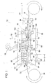
- FIG. 1 A preferred embodiment of a stretch-forming press 10 in accordance with the present invention is shown in FIG. 1.
- Press 10 includes a progressive tool 12 having a ram 14 that is stroked by the action of a crankshaft 16, cycling progressive tool 12 between an open condition and a closed condition.
- the stroke 18 of the ram 14 results in a known open height and shut height of ram 14 when progressive tool 12 is in its open and closed conditions, respectively.
- Progressive tool 12 is comprised of three stations and a roll feeding mechanism 20 that advances a coil of sheet metal through the progressive tool.
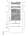
- a pre-forming station 22 has a pair of spaced apart dies 24, 26 that will stretch-form two alignment recesses such as channels 28 (seen in FIG. 2) in a central portion of a sheet metal strip 32 provided from an input coil 34.
- Sheet metal strip 32 may be formed of any material having elastic properties that result in snap-back when the material of sheet metal strip 32 is stretch-formed.
- the material of sheet metal strip 32 may be, e.g., 310 stainless steel, 316 stainless steel, titanium, aluminum, nickel 200, etc.
- Die 24 is surrounded by a jaw 36 and has a projection such as a rib 40 formed on its end Projection 40 is received by a recess such as a groove 42 formed in a base member 44 of progressive tool 12 that is positioned on the opposite side of sheet metal strip 32 from die 24.
- die 26 is surrounded by a jaw 46 and has a projection such as a rib 50 formed on its end Projection 50 is received by a recess such as a groove 52 formed in base member 44.
- Jaws 36, 46 are biased by corresponding biasing members 54, 56, respectively, into engagement with base member 44, thereby tightly gripping sheet metal strip 32 between jaws 36, 46 and base member 44, and preventing the draw-in of sheet metal strip 32 when progressive tool 12 is closed.
- biasing members 54, 56 are urethane rubber pads. Biasing members 54, 56 may be springs or any other suitable resilient member that will bias jaws 36, 46 into engagement with base member 44.
- sheet metal strip 32 is grasped tightly between jaws 36, 46 and base member 44.
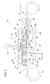
- dies 24, 26 are pressed into engagement with corresponding grooves 42, 52, respectively, stretch-forming channels 28 into sheet metal strip 32, as seen in FIG. 3. Since sheet metal strip 32 is grasped tightly between jaws 36, 46 and base member 44, no material is drawn into the stretch-formed regions of the sheet metal strip 32 from beyond jaws 36, 46. This prevents the non stretch-formed areas of the sheet metal strip 32 from being distorted.
- Dies 24, 26 and, therefore, channels 28, are spaced apart a distance D from one another, which is referred to as the pitch of the stamping being formed, as described in greater detail below.
- progressive tool 12 is opened, and sheet metal strip 32 is advanced in a direction of travel T through progressive tool 12.
- sheet metal strip 32 is advanced by feed mechanism 20 the distance D such that the trailing channel 28 of the two channels 28 formed at pre-fonning station 22 is aligned with die 26.
- a series of channels 28, each spaced a distance D from one another can be formed, allowing a continuously stamped sheet metal strip to be formed.
- a main forming station 58 is positioned downstream, with respect to the direction of travel T, of pre-forming station 22.
- Forming station 58 includes a die 59 and a pair of jaws 60, preferably spaced apart by distance D.
- jaws 60 include projections such as ribs 62 on ends thereof, which cooperate with recesses such as grooves 64 formed in base member 44 to grasp channels 28 of sheet metal strip 32 as progressive tool 12 closes.
- Die 59 also includes a pattern such as a plurality of ribs 66 and grooves 68 positioned between jaws 60, which mate with a corresponding pattern such as ribs 70 and grooves 72 formed in base member 44.
- Jaws 60 are biased by biasing members 61 into engagement with base member 44, thereby tightly gripping sheet metal strip 32 between jaws 60 and base member 44.
- biasing members 61 are urethane rubber pads. Biasing members 61 may be springs or any other suitable resilient member that will bias jaws 60 into engagement with base member 44. Since sheet metal strip 32 is grasped tightly between jaws 60 and base member 44, no material is drawn into the stretch-formed regions of the sheet metal strip 32 from beyond jaws 60.
- sheet metal strip 32 is grasped tightly between jaws 60 and base member 44.
- ribs 66 are received in corresponding grooves 72, and, similarly, ribs 70 are received in corresponding grooves 68, thereby stretch-forming a plurality of channels 74 into sheet metal strip 32 between the two pre-formed channels 28.
- the additional channels 74 and the pre-formed channels 28 together comprise a stamping 76, as seen in FIG. 2.
- Ribs 66, 70 and grooves 68, 72 of dies 59, 61, respectively, are configured such that stamping 76 is applied only to the central portion of the sheet metal strip 32. Consequently, edge portions 78, 80 of sheet metal strip 32 are free of any channels or other stampings.
- auxiliary jaws with corresponding biasing members may be provided in main forming station 58, each auxiliary jaw extending along one of the peripheral edge portions 78, 80.
- the auxiliary jaws act to prevent the draw-in of material from edge portions 78, 80 when channels 74 are shetch-formed, and to maintain sheet metal strip 32 in proper position.
- the illustrated embodiment is directed to a stamping formed exclusively of channels, the present invention is not limited to such stampings, but, rather, is applicable to any desired pattern that can be stretch-formed into a strip of sheet metal.
- the reduction of distortion that the present invention provides is equally applicable to patterns having many different configurations, and any such configuration is considered to be within the scope of the present invention.
- stamping of a desired length may be created.
- sheet metal strip 32 may be advanced a distance greater than the distance D during an open cycle of the press, e.g., a multiple of the distance D in order to ensure uniformity of stamping 76, or a sufficient distance that stamping 76 is advanced beyond progressive tool 12. This will create a non-stretch-formed area 77 in sheet metal strip 32, which will be equal in length to the distance the sheet is advanced during the open cycle.
- Non-stretch-formed area 77 provides an area where sheet metal strip 32 can be cut, thereby providing a stamped sheet metal plate of a desired length.
- sheet metal strip 32 is advanced the distance 2xD to create non-stretch-formed area 77.
- a separate pre-forming station 22 upstream of main forming station 58, it is possible to intermittently advance the sheet metal strip 32 a distance of 2xD (or any other multiple of D) to provide a non-stamped section of the sheet metal strip 32 that can be utilized to receive a cut.
- This non-stamped section can, in certain preferred embodiments, be folded over end caps onto leading and trailing ends of adjacent bipolar plates in the manufacture of electrochemical fuel cells.
- Feed mechanism 20 serves to advance sheet metal strip 32 through progressive tool 12.
- feed mechanism 20 is a roll feed mechanism and includes a lower roll 82 and an upper roll 84 that are driven by a motor (not shown) to pull sheet metal strip 32 the desired distance when progressive tool 12 is in its open condition, as seen in FIG. 1.
- a feed mechanism may be configured to push sheet metal strip 32 through progressive tool 12. Pulling sheet metal through progressive tool 12 with feed mechanism 20 is a preferred embodiment when sheet metal strip 32 is thin and cannot be pushed through progressive tool 12.
- Lower roll 82 is relieved in the area where stamping 76 of sheet metal strip 32 passes between lower roll 82 and upper roll 84, as can be seen in FIG. 2, in order to prevent damage to stamping 76 as sheet metal strip 32 is advanced.
- lower roll 82 engages only the edge portions 78, 80 of sheet metal strip 32 as it cooperates with upper roll 84 to pull sheet metal strip 32 through progressive tool 12.
- a leveling station 86 is positioned downstream, with respect to the direction of travel T, of forming station 58, and serves to reduce distortion created in sheet metal strip 32 at forming station 58 when stamping 76 is created.
- Leveling station 86 includes a pair of jaws 88 and 90, which are positioned on opposite sides of sheet metal strip 32.
- Jaw 88 is slidably received in a recess 92 formed in a jaw housing 94.
- Jaw 88 has a projection such as a rib 98 on one end thereof that is configured to mate with a corresponding channel 28 of sheet metal strip 32.
- Jaw 90 is slidably received in a recess 102 formed in base member 44.
- Jaw 90 has a recess such as a groove 108 on one end thereof configured to mate with a the corresponding channel 28 of sheet metal strip 32 when progressive tool 12 is closed, such that jaws 88, 90 cooperate to tightly grasp sheet metal strip 32.
- Jaws 88, 90 are biased by biasing members 104, 106, respectively, into engagement with each other, thereby tightly gripping sheet metal strip 32 between them.
- biasing members 104, 106 are urethane rubber pads.
- Biasing members 104, 106 may be springs or any other suitable resilient member that will bias jaws 88, 90 into engagement with each other.
- sheet metal strip 32 is advanced through progressive tool 12 to leveling station 86 by feed mechanism 20 the distance D such that rib 98 of jaw 88 and groove 108 of jaw 90 are properly aligned with a corresponding channel 28.
- progressive tool 12 starts to close, jaws 88, 90 tightly grasp sheet metal strip 32 along the corresponding channel 28.
- progressive tool 12 is at a position of initial contact with sheet metal strip 32.
- the distance L between the most downstream jaw 60 of forming station 58 and jaws 88, 90 of leveling station 86 is equal to the distance D less the snap-back distance of the sheet metal that is, the pitch of stamping 76 less the snap-back distance.
- jaws 88, 90 retract into corresponding recesses 92, 102, respectively, to the position illustrated in FIG. 5, where ram 14 is shown in its lowest position and progressive tool 12 is shown being completely closed.
- Recesses 92, 102 are configured such that a centerline of travel 110 of each of jaws 88, 90 is at an acute angle 112 with respect to the direction of travel T of sheet metal strip 32.
- the movement of each of jaws 88, 90 consists of both a vertical and horizontal component. More specifically, jaws 88, 90 move both in a perpendicular direction, that is, in a direction substantially perpendicular to the direction of travel T of sheet metal strip 32 (vertically as seen in the illustrated embodiment of FIG.
- jaws 88, 90 are spaced a distance L' from the most downstream jaw 60 of forming station 58, which is a distance greater than the distance L.
- the lateral motion of jaws 88, 90 at the pre-formed channel 8 has the effect of stretching stamping 76 in the direction of travel T of sheet metal strip 32, resulting in an over-pull of stamping 76.
- each of pre-forming station 22, main forming station 58 and leveling station 86 release stamping 76, and the over-pull produced by jaws 88, 90 in leveling station 86 snaps back an amount necessary to eliminate the residual stress of stamping 76 relative to the un-stamped peripheral edge portions 78, 80.
- Angle 112 is sized such that jaws 88, 90 stretch sheet metal strip 32 an amount capable of countering effects of snap-back that result from stamping the desired pattern.
Landscapes
- Engineering & Computer Science (AREA)
- Mechanical Engineering (AREA)
- Shaping Metal By Deep-Drawing, Or The Like (AREA)
- Press Drives And Press Lines (AREA)
- Forging (AREA)
- Superconductors And Manufacturing Methods Therefor (AREA)
- Vehicle Body Suspensions (AREA)
Claims (29)
- Verfahren zum Reduzieren von Verzug in einem geprägten Blechstreifen (32) mit folgenden Schritten:Bereitstellen einer Streckformpresse (10) mit einer Hauptformgebungsstation (58) und einer Nivellierstation bzw. Richtstation (86);Prägen eines gewünschten Musters auf den Streifen Blech (32) in der Hauptformgebungsstation (58) durch Schließen der Streckformpresse (10);Vorschub des Streifens Blech (32) durch die Streckformpresse (10) in einer Transportrichtung (T) über einen gewünschten Abstand;dadurch gekennzeichnet, dass:der gewünschte Abstand ein solcher ist, dass das gewünschte Muster mit der Nivellierstation (86) ausgerichtet ist; wobei die Nivellierstation (86) ein Paar Backen (88, 90) hat, wobei jede Backe in einer Ausnehmung (92, 102) verschieblich aufgenommen ist, die relativ zur Transportrichtung (T) des Streifens Blech (32) durch die Streckformpresse (10) in einem spitzen Winkel (102) geneigt ist; und ferner mit dem Schritt des Schließens der Streckformpresse (10), so dass die Backen (88, 90) der Nivellierstation (86) mit dem Streifen Blech (32) eingreifen und einen Teil des Streifens Blech (32) mit dem gewünschten Muster in der Transportrichtung (T) über eine gewählte Strecke strecken, wenn und die Backen (88, 90) in die jeweiligen Ausnehmungen (92, 102) eingleiten, wenn die Streckformpresse (10) geschlossen wird.
- Verfahren nach Anspruch 1, bei dem der spitze Winkel (102) und eine daraus resultierende Fahrstrecke der Backen (88, 90) entlang der Ausnehmung (92, 102) so bemessen ist, dass die gewählte Strecke ausreicht, den aus dem Prägen des gewünschten Musters resultierenden Zurückschnapp-Effekten entgegenzuwirken.
- Verfahren nach Anspruch 1, bei dem das gewünschte Muster eine Vielzahl von Kanälen (74) umfasst.
- Verfahren nach Anspruch 1, das ferner die folgenden Schritte umfasst:Bereitstellen einer Vorformgebungsstation (22) in der Streckformpresse (10), im Bezug auf die Transportrichtung (T) vor der Hauptformgebungsstation (58); undPrägen eines Paars beabstandeter Kanäle (28) in den Streifen Blech (32) an der Vorformgebungsstation (22).
- Verfahren nach Anspruch 4, bei dem der Abstand (D) zwischen den auseinanderliegenden Kanälen (28) der gleiche Abstand wie der gewünschte Abstand (D) ist.
- Verfahren nach Anspruch 4, bei dem der Schritt des Prägens der beabstandeten Kanäle (28) durch einen Stempel (24, 26) vorgenommen wird.
- Verfahren nach Anspruch 6, bei dem jeder Stempel (24, 26) von einer Backe (36, 46) umgeben ist, welche durch ein Urethan-Gummikissen mit einem Basiselement (44) der Streckformpresse (10) in Eingriff gedrückt wird.
- Verfahren nach Anspruch 1, bei dem der Schritt des Vorschubs des Streifens Blech (32) durch ein Rollenpaar (82, 84) durchgeführt wird.
- Verfahren nach Anspruch 1, welches ferner folgende Schritte umfasst:Öffnen der Streckformpresse (10);Vorschieben des Streifens Blech (32) durch die Streckformpresse (10).
Wiederholung der Schritte des Prägens eines gewünschten Musters, des Vorschiebens des Streifens Blech (32), des Schließens der Streckformpresse (10), des Öffnens der Streckformpresse, und des Vorschiebens des Streifens Blech (32) für eine gewünschte Anzahl von Durchgängen, um einen Streifen Blech (32) herzustellen, der entlang seiner Länge das kontinuierlich geprägte gewünschte Muster aufweist. - Verfahren nach Anspruch 9, welches ferner den Schritt des intermittierenden Vorschubs des Streifens Blech (32) durch die Streckformpresse (10) um eine größere Strecke als benötigt umfasst, um das gewünschte Muster mit der Nivellierstation (86) auszurichten, wenn der Blechstreifen (32) von der Hauptformgebungsstation (58) zu der Nivellierstation (86) vorgeschoben wird, um einen Teil des Blechstreifens (32) ohne das gewünschte Muster entlang seiner Länge herzustellen.
- Streckformpresse (10) für die kontinuierliche Zuführung von Blech (32), welche in Kombination umfasst:eine Stoßeinrichtung (14);ein Basiselement (44);einen zum Vorschub eines Streifens Blech (32) durch die Streckformpresse (10) ausgebildeten Zuführmechanismus (20);eine Formgebungsstation (58) mit einem Stempel (59), welcher zum Ausformen eines gewünschten Musters in einem Streifen Blech (32) ausgebildet ist, dadurch gekennzeichnet, dasseine Nivellierstation bzw. Richtstation (86) mit einem Paar gegenüberliegender Backen (88, 90) vorgesehen ist, welche verschiebbar in entsprechenden Ausnehmungen (92, 102) der Streckformpresse (10) aufgenommen sind, wobei die Backen (88, 90) in einem Winkel (102) relativ zu einer Transportrichtung (T) eines Streifens Blech (32) durch die Nivellierstation (86) angeordnet sind.
- Streckformpresse (10) nach Anspruch 11, bei welcher der Stempel (59) zum Herstellen einer Vielzahl von Kanälen (74) in einen Streifen Blech (32) ausgebildet ist.
- Streckformpresse (10) nach Anspruch 12, bei welcher jede Backe (88, 90) der Formgebungsstation (58) zu der anderen Backe hin durch eine Vorspannvorrichtung (104, 106) vorgespannt wird.
- Streckformpresse (10) nach Anspruch 13, bei welcher jede Vorspannvorrichtung (104, 106) ein Urethan-Gummikissen umfasst.
- Streckformpresse (10) nach Anspruch 11, welche ferner eine Vorformstation (22) mit einem Paar Stempel (24, 26) umfasst, welche zum Ausformen eines Paars von Ausrichtungsausnehmungen (28) in den Blechstreifen (32) ausgebildet sind.
- Streckformpresse (10) nach Anspruch 15, bei welcher die Ausrichtungsausnehmungen (28) Kanäle sind.
- Streckformpresse (10) nach Anspruch 15, bei welcher jeder der Stempel (24, 26) der Vorformstation (22) von einer Backe (36, 46) umgeben ist.
- Streckformpresse (10) nach Anspruch 17, bei welcher jede Backe (36, 46) der Vorformstation (22) zum Basiselement (44) hin durch eine Vorspannvorrichtung (54, 56) vorgespannt wird.
- Streckformpresse (10) nach Anspruch 18, bei welcher jede Vorspannvorrichtung (54, 56) der Vorformstation (22) ein Urethan-Gummikissen umfasst.
- Streckformpresse (10) nach Anspruch 11, bei welcher eine Backe (90) der Nivellierstation (86) verschiebbar in einer Ausnehmung (102) des Basiselements (44) aufgenommen wird und die andere Backe (88) der Nivellierstation (86) verschiebbar in einer in einem Backengehäuse (94) ausgeformten Ausnehmung (32) aufgenommen wird.
- Streckformpresse (10) nach Anspruch 11, bei welcher der Winkel (112) so bemessen ist, dass, wenn die Stoßeinrichtung (14) sich über dem Basiselement schießt, die Backen (88, 89) einen Teil eines Streifens geprägten Blechs (32) über einen Abstand strecken, welcher genügt, um den aus dem Prägen eines gewünschten Musters auf einen Streifen eines Blechs (32) mit der Formgebungsstation (58) resultierenden Zurückschnapp-Effekten entgegenzuwirken.
- Streckformpresse (10) nach Anspruch 11, welche ferner umfasst:eine Vorformstation (22) mit einem Paar beabstandeter Stempel (24, 26), welche so ausgebildet sind, dass sie zu Ausnehmungen (42, 52) passen, welche in dem Basiselement (44) ausgeformt sind, um Ausrichtungsausnehmungen (28) in den in der Streckformpresse (10) geformten Streifen des Blechs (32) auszuformen, wobei jeder Stempel (24, 26) von einer Backe (36, 46) umgeben ist und wobei jede Backe zu dem Basiselement (44) hin durch eine Vorspannvorrichtung (54, 56) vorgespannt ist;wobei die Formgebungsstation (58) ferner ein Paar beabstandeter Backen (60) umfasst, welche so ausgebildet sind, dass sie zu den Ausrichtungsausnehmungen (28) passen, welche in den Streifen Blech (32) an der Vorformgebungsstation (22) ausgeformt werden, wobei jede der beabstandeten Backen (60) zu dem Basiselement (44) hin durch eine Vorspannvorrichtung (61) vorgespannt wird;und wobei die Backen (88, 90) der Nivellierstation (86) zu dem Basiselement (44) hin durch eine Vorspannvorrichtung (104, 106) vorgespannt werden.
- Streckformpresse (10) nach Anspruch 22, bei welcher die Ausrichtungsausnehmungen (28) Kanäle sind.
- Streckformpresse (10) nach Anspruch 22, bei welcher jede Vorspannvorrichtung (54, 56, 61, 104, 106) der Vorformgebungsstation (22), der Haupformgebungsstation (58) und der Nivellierstation (86) ein Urethan-Gummikissen ist.
- Streckformpresse (10) nach Anspruch 22, bei welcher die Stempel (24, 26, 59) so ausgebildet sind, dass sie eine Vielzahl von Kanälen (28, 74) in einem Streifen Blech (32) ausformen.
- Streckformpresse (10) nach Anspruch 22, bei welcher der Zuführmechanismus (20) ein Paar Rollen (82, 84) umfasst, welche so ausgebildet sind, dass sie zusammen einen Streifen Blech (32) erfassen und ihn durch die Streckformpresse (10) ziehen.
- Streckformpresse (10) nach Anspruch 26, bei welcher eine der Rollen (82) in ihrem Mittelteil entlastet ist.
- Streckformpresse (10) nach Anspruch 22, bei welcher eine Backe (90) verschiebbar in einer Ausnehmung (102) des Basiselements (44) aufgenommen wird und die andere Backe (88) verschiebbar in einer in einem Backengehäuse (94) ausgeformten Ausnehmung (92) aufgenommen wird
- Streckformpresse (10) nach Anspruch 22, bei welcher der Winkel (102) so bemessen ist, dass wenn die Stoßeinrichtung (14) sich über dem Basiselement schießt, die Backen (88, 89) einen Teil eines Streifens geprägten Blechs (32) über einen Abstand strecken, welcher genügt, um den aus dem Prägen eines gewünschten Musters auf einen Streifen eines Blechs (32) mit der Formgebungsstation (58) resultierenden Zurückschnapp-Effekten entgegenzuwirken.
Applications Claiming Priority (3)
| Application Number | Priority Date | Filing Date | Title |
|---|---|---|---|
| US10/350,863 US6772617B1 (en) | 2003-01-24 | 2003-01-24 | Method and apparatus for in-situ leveling of progressively formed sheet metal |
| US350863 | 2003-01-24 | ||
| PCT/US2004/001156 WO2004067202A1 (en) | 2003-01-24 | 2004-01-16 | Method and apparatus for in-situ leveling of progressively formed sheet metal |
Publications (2)
| Publication Number | Publication Date |
|---|---|
| EP1585608A1 EP1585608A1 (de) | 2005-10-19 |
| EP1585608B1 true EP1585608B1 (de) | 2006-09-27 |
Family
ID=32735665
Family Applications (1)
| Application Number | Title | Priority Date | Filing Date |
|---|---|---|---|
| EP04702989A Expired - Lifetime EP1585608B1 (de) | 2003-01-24 | 2004-01-16 | Verfahren und vorrichtung zum in-situ-richten von fortschreitend geformtem blech |
Country Status (11)
| Country | Link |
|---|---|
| US (1) | US6772617B1 (de) |
| EP (1) | EP1585608B1 (de) |
| KR (1) | KR20050092043A (de) |
| CN (1) | CN100351026C (de) |
| AT (1) | ATE340660T1 (de) |
| BR (1) | BRPI0406728A (de) |
| CA (1) | CA2512245A1 (de) |
| DE (1) | DE602004002559T2 (de) |
| ES (1) | ES2274416T3 (de) |
| MX (1) | MXPA05007564A (de) |
| WO (1) | WO2004067202A1 (de) |
Families Citing this family (14)
| Publication number | Priority date | Publication date | Assignee | Title |
|---|---|---|---|---|
| WO2004105978A1 (de) * | 2003-05-30 | 2004-12-09 | Emitec Gesellschaft Für Emissionstechnologie Mbh | Herstellung eines strukturierten bleches für abgasbehandlungseinrichtungen |
| JP4065832B2 (ja) * | 2003-12-03 | 2008-03-26 | 本田技研工業株式会社 | 燃料電池用金属製セパレータのプレス成形装置及びプレス成形方法 |
| US20080199751A1 (en) * | 2007-02-20 | 2008-08-21 | Commonwealth Scientific And Industrial Research Organisation | Bipolar plate for an air breathing fuel cell stack |
| JP5383174B2 (ja) * | 2008-12-19 | 2014-01-08 | 株式会社エフ・シー・シー | シート状材料の折り曲げ加工装置 |
| US20130343897A1 (en) * | 2012-06-21 | 2013-12-26 | David A. Collins | Helix Type Vertical Axis Turbine Blades and Method for Continuously Making Same |
| WO2014196277A1 (ja) * | 2013-06-04 | 2014-12-11 | 日産自動車株式会社 | セパレータの歪みを除去する成形方法およびセパレータの歪みを除去する成形装置 |
| KR20160136609A (ko) * | 2015-05-20 | 2016-11-30 | 현대자동차주식회사 | 프로그레시브 성형장치 및 그 성형방법 |
| US10239109B2 (en) | 2016-03-01 | 2019-03-26 | Stolle Machinery Company, Llc | Shell system locating assembly for shells |
| CN106826020A (zh) * | 2017-03-10 | 2017-06-13 | 无锡先导智能装备股份有限公司 | 焊带预拉伸机构 |
| CN113245445B (zh) * | 2021-05-25 | 2022-12-20 | 深圳市吉百顺科技有限公司 | 一种用于电感加工的冲压成型一体设备 |
| CN114523023B (zh) * | 2022-02-15 | 2025-01-17 | 河北光兴半导体技术有限公司 | 用于燃料电池单极板的冲压系统及冲压成型方法 |
| DE102022114501B4 (de) * | 2022-06-09 | 2025-07-17 | Schaeffler Technologies AG & Co. KG | Werkzeugvorrichtung zur Herstellung einer Bipolarplatte und Verfahren |
| CN117139478B (zh) * | 2023-06-30 | 2024-09-06 | 西安咏空电子科技有限公司 | 一种锂电池壳体冲压生产线 |
| CN119702863B (zh) * | 2024-12-04 | 2025-11-07 | 东莞市东众五金制品有限公司 | 一种铝合金板材连续冲压模具 |
Family Cites Families (78)
| Publication number | Priority date | Publication date | Assignee | Title |
|---|---|---|---|---|
| CH168501A (de) * | 1932-12-21 | 1934-04-15 | Ver Deutsche Metallwerke Ag | Einrichtung zur Herstellung von plan gerichteten Metallbahnen mit parallelen und geradlinig verlaufenden Kanten. |
| US2352442A (en) * | 1940-05-23 | 1944-06-27 | Loewy Eng Co Ltd | Straightening machine for metal bars |
| GB614186A (en) * | 1946-07-05 | 1948-12-10 | Bigwood Joshua & Son Ltd | Improvements in gripping devices for sheet metal stretching machines |
| US3430476A (en) * | 1966-11-14 | 1969-03-04 | American Cyanamid Co | Corrugating machine |
| US4175165A (en) | 1977-07-20 | 1979-11-20 | Engelhard Minerals & Chemicals Corporation | Fuel cell system utilizing ion exchange membranes and bipolar plates |
| US4233833A (en) * | 1978-06-05 | 1980-11-18 | United States Gypsum Company | Method for stretching sheet metal and structural members formed therefrom |
| US4169917A (en) | 1978-07-10 | 1979-10-02 | Energy Research Corporation | Electrochemical cell and separator plate thereof |
| IT1202757B (it) | 1978-07-10 | 1989-02-09 | Elche Ltd | Setto bipolare per celle elettrochimiche |
| US4982593A (en) * | 1986-01-15 | 1991-01-08 | Washington Steel Corporation | Gripper means for stretcher leveler apparatus |
| US4510212A (en) | 1983-10-12 | 1985-04-09 | The United States Of America As Represented By The United States Department Of Energy | Solid oxide fuel cell having compound cross flow gas patterns |
| US4476197A (en) | 1983-10-12 | 1984-10-09 | The United States Of America As Represented By The United States Department Of Energy | Integral manifolding structure for fuel cell core having parallel gas flow |
| US4604331A (en) | 1984-05-29 | 1986-08-05 | The United States Of America As Represented By The United States Department Of Energy | Fuel cell separator plate with bellows-type sealing flanges |
| JPS60253170A (ja) | 1984-05-29 | 1985-12-13 | Ishikawajima Harima Heavy Ind Co Ltd | 積層燃料電池 |
| JPH0736334B2 (ja) | 1984-07-13 | 1995-04-19 | 三菱電機株式会社 | 溶融炭酸塩形燃料電池の電極 |
| US4548876A (en) | 1984-10-17 | 1985-10-22 | The United States Of America As Represented By The United States Department Of Energy | Integrated current collector and catalyst support |
| US4751838A (en) * | 1985-11-18 | 1988-06-21 | Red Bud Industries, Inc. | Machine and process for leveling sheet metal strip |
| US4631239A (en) | 1985-12-04 | 1986-12-23 | Westinghouse Electric Corp. | Fuel cell plates with improved arrangement of process channels for enhanced pressure drop across the plates |
| US4853301A (en) | 1985-12-04 | 1989-08-01 | The United States Of America As Represented By The United States Department Of Energy | Fuel cell plates with skewed process channels for uniform distribution of stack compression load |
| JPH0626126B2 (ja) | 1986-06-13 | 1994-04-06 | 株式会社日立製作所 | 燃料電池 |
| US4702973A (en) | 1986-08-25 | 1987-10-27 | Institute Of Gas Technology | Dual compartment anode structure |
| JP2569550B2 (ja) | 1987-05-08 | 1997-01-08 | 石川島播磨重工業株式会社 | 燃料電池の温度分布改善方法 |
| US4857420A (en) | 1987-10-13 | 1989-08-15 | International Fuel Cell Corporation | Method of making monolithic solid oxide fuel cell stack |
| US5227256A (en) | 1989-05-03 | 1993-07-13 | Institute Of Gas Technology | Fully internal manifolded fuel cell stack |
| NL8901800A (nl) | 1989-07-12 | 1991-02-01 | Stichting Energie | Separatorplaat voor toepassing in een gasbrandstofcel, welke een verzameling electroden omvat, alsmede stapeling van brandstofcellen. |
| US4983472A (en) | 1989-11-24 | 1991-01-08 | International Fuel Cells Corporation | Fuel cell current collector |
| DE4206490C2 (de) | 1992-03-02 | 1994-03-10 | Fraunhofer Ges Forschung | Elektrisch leitfähige Gasverteilerstruktur für eine Brennstoffzelle und Verfahren zu ihrer Herstellung |
| US5298342A (en) | 1992-10-20 | 1994-03-29 | M-C Power Corporation | Fuel cell crossover arrestor and pressure seal |
| US5362578A (en) | 1992-12-08 | 1994-11-08 | Institute Of Gas Technology | Integrated main rail, feed rail, and current collector |
| IT1270878B (it) | 1993-04-30 | 1997-05-13 | Permelec Spa Nora | Migliorata cella elettrochimica utilizzante membrane a scambio ionico e piatti bipolari metallici |
| JP2948441B2 (ja) | 1993-06-29 | 1999-09-13 | 三洋電機株式会社 | 平板型固体電解質燃料電池 |
| US5424144A (en) | 1993-10-21 | 1995-06-13 | M-C Power Corporation | One piece separator plate with insert ring step design |
| US5527363A (en) | 1993-12-10 | 1996-06-18 | Ballard Power Systems Inc. | Method of fabricating an embossed fluid flow field plate |
| US5460897A (en) | 1994-03-18 | 1995-10-24 | Allied Signal Inc. | Solid oxide fuel cell stacking assembly |
| DK0746879T3 (da) | 1994-03-21 | 2000-05-08 | Ztek Corp | Elektrokemisk konverter med optimal trykfordeling |
| DE4410711C1 (de) | 1994-03-28 | 1995-09-07 | Forschungszentrum Juelich Gmbh | Metallische bipolare Platte für HT-Brennstoffzellen und Verfahren zur Herstellung desselben |
| ES2145208T3 (es) | 1994-05-20 | 2000-07-01 | Int Fuel Cells Corp | Conjunto de placa refrigerante para un apilamiento de celdas de combustible. |
| US5773160A (en) | 1994-06-24 | 1998-06-30 | Ballard Power Systems Inc. | Electrochemical fuel cell stack with concurrent flow of coolant and oxidant streams and countercurrent flow of fuel and oxidant streams |
| US5558955A (en) | 1994-10-07 | 1996-09-24 | International Fuel Cells Corporation | Cathode reactant flow field component for a fuel cell stack |
| US5863671A (en) | 1994-10-12 | 1999-01-26 | H Power Corporation | Plastic platelet fuel cells employing integrated fluid management |
| RU2174728C2 (ru) | 1994-10-12 | 2001-10-10 | Х Пауэр Корпорейшн | Топливный элемент, использующий интегральную технологию пластин для распределения жидкости |
| AU4186096A (en) | 1994-12-17 | 1996-07-03 | Loughborough University Innovations Limited | Electrolytic and fuel cell arrangements |
| AUPN173595A0 (en) | 1995-03-15 | 1995-04-06 | Ceramic Fuel Cells Limited | Fuel cell interconnect device |
| US5726105A (en) | 1995-04-20 | 1998-03-10 | International Fuel Cells | Composite article |
| DE19547700C2 (de) | 1995-12-20 | 1998-09-17 | Forschungszentrum Juelich Gmbh | Elektrodensubstrat für eine Brennstoffzelle |
| DE19602315C2 (de) | 1996-01-23 | 2001-10-11 | Siemens Ag | Flüssigkeitsgekühlte Brennstoffzelle mit Verteilungskanälen |
| JP3540491B2 (ja) | 1996-03-07 | 2004-07-07 | 政廣 渡辺 | 燃料電池及び電解セル並びにその冷却・除湿方法 |
| US6054228A (en) | 1996-06-06 | 2000-04-25 | Lynntech, Inc. | Fuel cell system for low pressure operation |
| JP3499090B2 (ja) | 1996-08-07 | 2004-02-23 | 本田技研工業株式会社 | 燃料電池 |
| US5795665A (en) | 1996-08-19 | 1998-08-18 | Energy Research Corporation | Fuel cell sub-assembly with a plurality of dimples |
| US5798187A (en) | 1996-09-27 | 1998-08-25 | The Regents Of The University Of California | Fuel cell with metal screen flow-field |
| US5773161A (en) | 1996-10-02 | 1998-06-30 | Energy Research Corporation | Bipolar separator |
| US6037073A (en) | 1996-10-15 | 2000-03-14 | Lockheed Martin Energy Research Corporation | Bipolar plate/diffuser for a proton exchange membrane fuel cell |
| JPH10125338A (ja) | 1996-10-22 | 1998-05-15 | Fuji Electric Co Ltd | 固体高分子電解質型燃料電池 |
| AU7181998A (en) | 1996-11-14 | 1998-06-03 | Dais Corporation | Fuel cell stack assembly |
| US5707755A (en) | 1996-12-09 | 1998-01-13 | General Motors Corporation | PEM/SPE fuel cell |
| US5776624A (en) | 1996-12-23 | 1998-07-07 | General Motors Corporation | Brazed bipolar plates for PEM fuel cells |
| JP3077618B2 (ja) | 1997-03-05 | 2000-08-14 | 富士電機株式会社 | 固体高分子電解質型燃料電池 |
| FR2764443B1 (fr) | 1997-06-10 | 1999-09-03 | Peugeot | Pile a combustible du type a distributeurs de reactifs en forme de plaques |
| US6048634A (en) | 1997-06-18 | 2000-04-11 | H Power Corporation | Fuel cell using water-soluble fuel |
| US5798188A (en) | 1997-06-25 | 1998-08-25 | E. I. Dupont De Nemours And Company | Polymer electrolyte membrane fuel cell with bipolar plate having molded polymer projections |
| JP3775618B2 (ja) | 1997-06-30 | 2006-05-17 | アイシン精機株式会社 | 燃料電池 |
| US5811202A (en) | 1997-08-05 | 1998-09-22 | M-C Power Corporation | Hybrid molten carbonate fuel cell with unique sealing |
| US5770327A (en) | 1997-08-15 | 1998-06-23 | Northwestern University | Solid oxide fuel cell stack |
| DE19735854C2 (de) | 1997-08-19 | 2002-08-01 | Daimler Chrysler Ag | Stromkollektor für eine Brennstoffzelle und Verfahren zu seiner Herstellung |
| US6033794A (en) | 1997-12-10 | 2000-03-07 | The United States Of America As Represented By The United States Department Of Energy | Multi-stage fuel cell system method and apparatus |
| US6099984A (en) | 1997-12-15 | 2000-08-08 | General Motors Corporation | Mirrored serpentine flow channels for fuel cell |
| US6051330A (en) | 1998-01-15 | 2000-04-18 | International Business Machines Corporation | Solid oxide fuel cell having vias and a composite interconnect |
| US6096450A (en) | 1998-02-11 | 2000-08-01 | Plug Power Inc. | Fuel cell assembly fluid flow plate having conductive fibers and rigidizing material therein |
| EP1060534B1 (de) | 1998-02-27 | 2003-01-22 | Corning Incorporated | Flexible anorganische elektrolytische brennstoffzellenausführung |
| JP4205774B2 (ja) | 1998-03-02 | 2009-01-07 | 本田技研工業株式会社 | 燃料電池 |
| US6040076A (en) | 1998-03-03 | 2000-03-21 | M-C Power Corporation | One piece fuel cell separator plate |
| US6071635A (en) | 1998-04-03 | 2000-06-06 | Plug Power, L.L.C. | Easily-formable fuel cell assembly fluid flow plate having conductivity and increased non-conductive material |
| US6074692A (en) | 1998-04-10 | 2000-06-13 | General Motors Corporation | Method of making MEA for PEM/SPE fuel cell |
| DE19821767C2 (de) | 1998-05-14 | 2000-06-08 | Siemens Ag | Stapel aus Brennstoffzellen mit Flüssigkeitskühlung und Verfahren zur Kühlung eines BZ-Stapels |
| US6054231A (en) | 1998-07-24 | 2000-04-25 | Gas Research Institute | Solid oxide fuel cell interconnector |
| US6261710B1 (en) | 1998-11-25 | 2001-07-17 | Institute Of Gas Technology | Sheet metal bipolar plate design for polymer electrolyte membrane fuel cells |
| US6408670B1 (en) * | 1999-08-25 | 2002-06-25 | George Trapp | Carrierless progressive die system |
| JP4476463B2 (ja) | 2000-09-26 | 2010-06-09 | 本田技研工業株式会社 | 燃料電池用セパレータと燃料電池 |
-
2003
- 2003-01-24 US US10/350,863 patent/US6772617B1/en not_active Expired - Fee Related
-
2004
- 2004-01-16 BR BR0406728-2A patent/BRPI0406728A/pt not_active IP Right Cessation
- 2004-01-16 ES ES04702989T patent/ES2274416T3/es not_active Expired - Lifetime
- 2004-01-16 DE DE602004002559T patent/DE602004002559T2/de not_active Expired - Fee Related
- 2004-01-16 CN CNB2004800022043A patent/CN100351026C/zh not_active Expired - Fee Related
- 2004-01-16 MX MXPA05007564A patent/MXPA05007564A/es active IP Right Grant
- 2004-01-16 WO PCT/US2004/001156 patent/WO2004067202A1/en not_active Ceased
- 2004-01-16 CA CA002512245A patent/CA2512245A1/en not_active Abandoned
- 2004-01-16 KR KR1020057013016A patent/KR20050092043A/ko not_active Ceased
- 2004-01-16 AT AT04702989T patent/ATE340660T1/de not_active IP Right Cessation
- 2004-01-16 EP EP04702989A patent/EP1585608B1/de not_active Expired - Lifetime
Also Published As
| Publication number | Publication date |
|---|---|
| MXPA05007564A (es) | 2005-09-21 |
| CN1738690A (zh) | 2006-02-22 |
| WO2004067202A1 (en) | 2004-08-12 |
| CN100351026C (zh) | 2007-11-28 |
| DE602004002559D1 (de) | 2006-11-09 |
| CA2512245A1 (en) | 2004-08-12 |
| ES2274416T3 (es) | 2007-05-16 |
| ATE340660T1 (de) | 2006-10-15 |
| US20040144151A1 (en) | 2004-07-29 |
| HK1086786A1 (zh) | 2006-09-29 |
| EP1585608A1 (de) | 2005-10-19 |
| US6772617B1 (en) | 2004-08-10 |
| KR20050092043A (ko) | 2005-09-16 |
| BRPI0406728A (pt) | 2005-12-20 |
| DE602004002559T2 (de) | 2007-06-21 |
Similar Documents
| Publication | Publication Date | Title |
|---|---|---|
| EP1585608B1 (de) | Verfahren und vorrichtung zum in-situ-richten von fortschreitend geformtem blech | |
| AU664917B2 (en) | Two stage die set | |
| DE2928664A1 (de) | Stanzpresse und verfahren zur herstellung von mit verschluessen versehenen dosenboeden | |
| CN109759523A (zh) | 一种汽车车架横梁异型端头在线切断方法 | |
| US6067834A (en) | Method for stamping bowed piece-parts | |
| KR101637964B1 (ko) | 코루게이트 핀 제조장치 | |
| CN108356144A (zh) | 一种用于安全气囊基板生产的冲压方法及模具 | |
| CN215467411U (zh) | 一种汽车底盘用套管的旋切模 | |
| CN214417454U (zh) | 汽车白车身级进模的侧翻边双动机构 | |
| US7849724B2 (en) | Method of manufacturing a ring-shaped member | |
| CN210059459U (zh) | 带导向装置的冲压机 | |
| CN215279479U (zh) | 一种高强度钢板双折弯级进模 | |
| HK1086786B (en) | Method and apparatus for in-situ leveling of progressively formed sheet metal | |
| CN215090180U (zh) | 一种用于冲压z形轮廓的冲模结构 | |
| RU2739057C1 (ru) | Способ изготовления П-образных изделий штамповкой из листа, например передней панели двери домашнего холодильника | |
| US9827606B2 (en) | Stamping apparatus having flared bead | |
| KR200326204Y1 (ko) | 캡의 걸림편 밴딩 금형과 상기 금형을 이용한프로그레시브 금형 장치 | |
| KR20210017804A (ko) | 프레스 장치 | |
| DE102022114501B4 (de) | Werkzeugvorrichtung zur Herstellung einer Bipolarplatte und Verfahren | |
| CN218475874U (zh) | 一种精密折半圆应用级进模 | |
| CN218574741U (zh) | 一种内外滑块整型装置 | |
| CN121402488A (zh) | 用于在板片中引入变形图案的方法和压力机 | |
| US6079308A (en) | Apparatus for sheet-metal plate processing to be employed at inclined C-frame presses | |
| CN210648108U (zh) | 一种离合器波形弹簧片的加工模具 | |
| JPS61229418A (ja) | 帯状素板の矯正方法 |
Legal Events
| Date | Code | Title | Description |
|---|---|---|---|
| PUAI | Public reference made under article 153(3) epc to a published international application that has entered the european phase |
Free format text: ORIGINAL CODE: 0009012 |
|
| 17P | Request for examination filed |
Effective date: 20050714 |
|
| AK | Designated contracting states |
Kind code of ref document: A1 Designated state(s): AT BE BG CH CY CZ DE DK EE ES FI FR GB GR HU IE IT LI LU MC NL PT RO SE SI SK TR |
|
| AX | Request for extension of the european patent |
Extension state: AL LT LV MK |
|
| GRAP | Despatch of communication of intention to grant a patent |
Free format text: ORIGINAL CODE: EPIDOSNIGR1 |
|
| DAX | Request for extension of the european patent (deleted) | ||
| GRAS | Grant fee paid |
Free format text: ORIGINAL CODE: EPIDOSNIGR3 |
|
| GRAA | (expected) grant |
Free format text: ORIGINAL CODE: 0009210 |
|
| AK | Designated contracting states |
Kind code of ref document: B1 Designated state(s): AT BE BG CH CY CZ DE DK EE ES FI FR GB GR HU IE IT LI LU MC NL PT RO SE SI SK TR |
|
| PG25 | Lapsed in a contracting state [announced via postgrant information from national office to epo] |
Ref country code: IT Free format text: LAPSE BECAUSE OF FAILURE TO SUBMIT A TRANSLATION OF THE DESCRIPTION OR TO PAY THE FEE WITHIN THE PRESCRIBED TIME-LIMIT;WARNING: LAPSES OF ITALIAN PATENTS WITH EFFECTIVE DATE BEFORE 2007 MAY HAVE OCCURRED AT ANY TIME BEFORE 2007. THE CORRECT EFFECTIVE DATE MAY BE DIFFERENT FROM THE ONE RECORDED. Effective date: 20060927 Ref country code: AT Free format text: LAPSE BECAUSE OF FAILURE TO SUBMIT A TRANSLATION OF THE DESCRIPTION OR TO PAY THE FEE WITHIN THE PRESCRIBED TIME-LIMIT Effective date: 20060927 Ref country code: SI Free format text: LAPSE BECAUSE OF FAILURE TO SUBMIT A TRANSLATION OF THE DESCRIPTION OR TO PAY THE FEE WITHIN THE PRESCRIBED TIME-LIMIT Effective date: 20060927 Ref country code: SK Free format text: LAPSE BECAUSE OF FAILURE TO SUBMIT A TRANSLATION OF THE DESCRIPTION OR TO PAY THE FEE WITHIN THE PRESCRIBED TIME-LIMIT Effective date: 20060927 Ref country code: CZ Free format text: LAPSE BECAUSE OF FAILURE TO SUBMIT A TRANSLATION OF THE DESCRIPTION OR TO PAY THE FEE WITHIN THE PRESCRIBED TIME-LIMIT Effective date: 20060927 Ref country code: BE Free format text: LAPSE BECAUSE OF FAILURE TO SUBMIT A TRANSLATION OF THE DESCRIPTION OR TO PAY THE FEE WITHIN THE PRESCRIBED TIME-LIMIT Effective date: 20060927 Ref country code: LI Free format text: LAPSE BECAUSE OF FAILURE TO SUBMIT A TRANSLATION OF THE DESCRIPTION OR TO PAY THE FEE WITHIN THE PRESCRIBED TIME-LIMIT Effective date: 20060927 Ref country code: FI Free format text: LAPSE BECAUSE OF FAILURE TO SUBMIT A TRANSLATION OF THE DESCRIPTION OR TO PAY THE FEE WITHIN THE PRESCRIBED TIME-LIMIT Effective date: 20060927 Ref country code: NL Free format text: LAPSE BECAUSE OF FAILURE TO SUBMIT A TRANSLATION OF THE DESCRIPTION OR TO PAY THE FEE WITHIN THE PRESCRIBED TIME-LIMIT Effective date: 20060927 Ref country code: RO Free format text: LAPSE BECAUSE OF FAILURE TO SUBMIT A TRANSLATION OF THE DESCRIPTION OR TO PAY THE FEE WITHIN THE PRESCRIBED TIME-LIMIT Effective date: 20060927 Ref country code: CH Free format text: LAPSE BECAUSE OF FAILURE TO SUBMIT A TRANSLATION OF THE DESCRIPTION OR TO PAY THE FEE WITHIN THE PRESCRIBED TIME-LIMIT Effective date: 20060927 |
|
| REG | Reference to a national code |
Ref country code: GB Ref legal event code: FG4D |
|
| REG | Reference to a national code |
Ref country code: CH Ref legal event code: EP |
|
| REG | Reference to a national code |
Ref country code: IE Ref legal event code: FG4D |
|
| REF | Corresponds to: |
Ref document number: 602004002559 Country of ref document: DE Date of ref document: 20061109 Kind code of ref document: P |
|
| PG25 | Lapsed in a contracting state [announced via postgrant information from national office to epo] |
Ref country code: BG Free format text: LAPSE BECAUSE OF FAILURE TO SUBMIT A TRANSLATION OF THE DESCRIPTION OR TO PAY THE FEE WITHIN THE PRESCRIBED TIME-LIMIT Effective date: 20061227 Ref country code: DK Free format text: LAPSE BECAUSE OF FAILURE TO SUBMIT A TRANSLATION OF THE DESCRIPTION OR TO PAY THE FEE WITHIN THE PRESCRIBED TIME-LIMIT Effective date: 20061227 Ref country code: SE Free format text: LAPSE BECAUSE OF FAILURE TO SUBMIT A TRANSLATION OF THE DESCRIPTION OR TO PAY THE FEE WITHIN THE PRESCRIBED TIME-LIMIT Effective date: 20061227 |
|
| PG25 | Lapsed in a contracting state [announced via postgrant information from national office to epo] |
Ref country code: IE Free format text: LAPSE BECAUSE OF NON-PAYMENT OF DUE FEES Effective date: 20070116 |
|
| PG25 | Lapsed in a contracting state [announced via postgrant information from national office to epo] |
Ref country code: MC Free format text: LAPSE BECAUSE OF NON-PAYMENT OF DUE FEES Effective date: 20070131 |
|
| NLV1 | Nl: lapsed or annulled due to failure to fulfill the requirements of art. 29p and 29m of the patents act | ||
| PG25 | Lapsed in a contracting state [announced via postgrant information from national office to epo] |
Ref country code: PT Free format text: LAPSE BECAUSE OF FAILURE TO SUBMIT A TRANSLATION OF THE DESCRIPTION OR TO PAY THE FEE WITHIN THE PRESCRIBED TIME-LIMIT Effective date: 20070313 |
|
| REG | Reference to a national code |
Ref country code: CH Ref legal event code: PL |
|
| REG | Reference to a national code |
Ref country code: ES Ref legal event code: FG2A Ref document number: 2274416 Country of ref document: ES Kind code of ref document: T3 |
|
| EN | Fr: translation not filed | ||
| PLBE | No opposition filed within time limit |
Free format text: ORIGINAL CODE: 0009261 |
|
| STAA | Information on the status of an ep patent application or granted ep patent |
Free format text: STATUS: NO OPPOSITION FILED WITHIN TIME LIMIT |
|
| 26N | No opposition filed |
Effective date: 20070628 |
|
| PG25 | Lapsed in a contracting state [announced via postgrant information from national office to epo] |
Ref country code: GR Free format text: LAPSE BECAUSE OF FAILURE TO SUBMIT A TRANSLATION OF THE DESCRIPTION OR TO PAY THE FEE WITHIN THE PRESCRIBED TIME-LIMIT Effective date: 20061228 Ref country code: FR Free format text: LAPSE BECAUSE OF FAILURE TO SUBMIT A TRANSLATION OF THE DESCRIPTION OR TO PAY THE FEE WITHIN THE PRESCRIBED TIME-LIMIT Effective date: 20070525 |
|
| PG25 | Lapsed in a contracting state [announced via postgrant information from national office to epo] |
Ref country code: EE Free format text: LAPSE BECAUSE OF FAILURE TO SUBMIT A TRANSLATION OF THE DESCRIPTION OR TO PAY THE FEE WITHIN THE PRESCRIBED TIME-LIMIT Effective date: 20060927 |
|
| PG25 | Lapsed in a contracting state [announced via postgrant information from national office to epo] |
Ref country code: FR Free format text: LAPSE BECAUSE OF FAILURE TO SUBMIT A TRANSLATION OF THE DESCRIPTION OR TO PAY THE FEE WITHIN THE PRESCRIBED TIME-LIMIT Effective date: 20060927 |
|
| PGFP | Annual fee paid to national office [announced via postgrant information from national office to epo] |
Ref country code: ES Payment date: 20090206 Year of fee payment: 6 |
|
| PGFP | Annual fee paid to national office [announced via postgrant information from national office to epo] |
Ref country code: DE Payment date: 20090212 Year of fee payment: 6 |
|
| PGFP | Annual fee paid to national office [announced via postgrant information from national office to epo] |
Ref country code: GB Payment date: 20090204 Year of fee payment: 6 |
|
| PG25 | Lapsed in a contracting state [announced via postgrant information from national office to epo] |
Ref country code: LU Free format text: LAPSE BECAUSE OF NON-PAYMENT OF DUE FEES Effective date: 20070116 Ref country code: CY Free format text: LAPSE BECAUSE OF FAILURE TO SUBMIT A TRANSLATION OF THE DESCRIPTION OR TO PAY THE FEE WITHIN THE PRESCRIBED TIME-LIMIT Effective date: 20060927 |
|
| PG25 | Lapsed in a contracting state [announced via postgrant information from national office to epo] |
Ref country code: HU Free format text: LAPSE BECAUSE OF FAILURE TO SUBMIT A TRANSLATION OF THE DESCRIPTION OR TO PAY THE FEE WITHIN THE PRESCRIBED TIME-LIMIT Effective date: 20070328 Ref country code: TR Free format text: LAPSE BECAUSE OF FAILURE TO SUBMIT A TRANSLATION OF THE DESCRIPTION OR TO PAY THE FEE WITHIN THE PRESCRIBED TIME-LIMIT Effective date: 20060927 |
|
| GBPC | Gb: european patent ceased through non-payment of renewal fee |
Effective date: 20100116 |
|
| PG25 | Lapsed in a contracting state [announced via postgrant information from national office to epo] |
Ref country code: DE Free format text: LAPSE BECAUSE OF NON-PAYMENT OF DUE FEES Effective date: 20100803 |
|
| PG25 | Lapsed in a contracting state [announced via postgrant information from national office to epo] |
Ref country code: GB Free format text: LAPSE BECAUSE OF NON-PAYMENT OF DUE FEES Effective date: 20100116 |
|
| REG | Reference to a national code |
Ref country code: ES Ref legal event code: FD2A Effective date: 20110325 |
|
| PG25 | Lapsed in a contracting state [announced via postgrant information from national office to epo] |
Ref country code: ES Free format text: LAPSE BECAUSE OF NON-PAYMENT OF DUE FEES Effective date: 20110314 |
|
| PGFP | Annual fee paid to national office [announced via postgrant information from national office to epo] |
Ref country code: IT Payment date: 20090202 Year of fee payment: 6 |
|
| PGRI | Patent reinstated in contracting state [announced from national office to epo] |
Ref country code: IT Effective date: 20110616 |
|
| PG25 | Lapsed in a contracting state [announced via postgrant information from national office to epo] |
Ref country code: ES Free format text: LAPSE BECAUSE OF NON-PAYMENT OF DUE FEES Effective date: 20100117 |
|
| PGRI | Patent reinstated in contracting state [announced from national office to epo] |
Ref country code: IT Effective date: 20110616 |