EP1585608B1 - Method and apparatus for in-situ leveling of progressively formed sheet metal - Google Patents
Method and apparatus for in-situ leveling of progressively formed sheet metal Download PDFInfo
- Publication number
- EP1585608B1 EP1585608B1 EP04702989A EP04702989A EP1585608B1 EP 1585608 B1 EP1585608 B1 EP 1585608B1 EP 04702989 A EP04702989 A EP 04702989A EP 04702989 A EP04702989 A EP 04702989A EP 1585608 B1 EP1585608 B1 EP 1585608B1
- Authority
- EP
- European Patent Office
- Prior art keywords
- stretch
- sheet metal
- strip
- forming
- forming press
- Prior art date
- Legal status (The legal status is an assumption and is not a legal conclusion. Google has not performed a legal analysis and makes no representation as to the accuracy of the status listed.)
- Expired - Lifetime
Links
- 229910052751 metal Inorganic materials 0.000 title claims abstract description 137
- 239000002184 metal Substances 0.000 title claims abstract description 137
- 238000000034 method Methods 0.000 title claims description 21
- 238000011065 in-situ storage Methods 0.000 title 1
- 230000007246 mechanism Effects 0.000 claims abstract description 14
- 229920006311 Urethane elastomer Polymers 0.000 claims description 7
- 230000000694 effects Effects 0.000 claims description 6
- 230000001154 acute effect Effects 0.000 claims description 4
- 238000011144 upstream manufacturing Methods 0.000 claims description 2
- 230000000750 progressive effect Effects 0.000 description 34
- 239000000463 material Substances 0.000 description 11
- 238000004519 manufacturing process Methods 0.000 description 6
- 239000000446 fuel Substances 0.000 description 5
- 230000002093 peripheral effect Effects 0.000 description 4
- 230000008901 benefit Effects 0.000 description 3
- 239000000047 product Substances 0.000 description 3
- 230000008569 process Effects 0.000 description 2
- 229910000619 316 stainless steel Inorganic materials 0.000 description 1
- PXHVJJICTQNCMI-UHFFFAOYSA-N Nickel Chemical compound [Ni] PXHVJJICTQNCMI-UHFFFAOYSA-N 0.000 description 1
- RTAQQCXQSZGOHL-UHFFFAOYSA-N Titanium Chemical compound [Ti] RTAQQCXQSZGOHL-UHFFFAOYSA-N 0.000 description 1
- 238000009825 accumulation Methods 0.000 description 1
- 230000009471 action Effects 0.000 description 1
- 229910052782 aluminium Inorganic materials 0.000 description 1
- XAGFODPZIPBFFR-UHFFFAOYSA-N aluminium Chemical compound [Al] XAGFODPZIPBFFR-UHFFFAOYSA-N 0.000 description 1
- 239000007795 chemical reaction product Substances 0.000 description 1
- 230000001351 cycling effect Effects 0.000 description 1
- 230000009467 reduction Effects 0.000 description 1
- 230000001105 regulatory effect Effects 0.000 description 1
- 229910001220 stainless steel Inorganic materials 0.000 description 1
- 239000010935 stainless steel Substances 0.000 description 1
- 239000010936 titanium Substances 0.000 description 1
- 229910052719 titanium Inorganic materials 0.000 description 1
Images

Classifications
-
- B—PERFORMING OPERATIONS; TRANSPORTING
- B21—MECHANICAL METAL-WORKING WITHOUT ESSENTIALLY REMOVING MATERIAL; PUNCHING METAL
- B21D—WORKING OR PROCESSING OF SHEET METAL OR METAL TUBES, RODS OR PROFILES WITHOUT ESSENTIALLY REMOVING MATERIAL; PUNCHING METAL
- B21D31/00—Other methods for working sheet metal, metal tubes, metal profiles
- B21D31/04—Expanding other than provided for in groups B21D1/00 - B21D28/00, e.g. for making expanded metal
-
- B—PERFORMING OPERATIONS; TRANSPORTING
- B21—MECHANICAL METAL-WORKING WITHOUT ESSENTIALLY REMOVING MATERIAL; PUNCHING METAL
- B21D—WORKING OR PROCESSING OF SHEET METAL OR METAL TUBES, RODS OR PROFILES WITHOUT ESSENTIALLY REMOVING MATERIAL; PUNCHING METAL
- B21D1/00—Straightening, restoring form or removing local distortions of sheet metal or specific articles made therefrom; Stretching sheet metal combined with rolling
-
- B—PERFORMING OPERATIONS; TRANSPORTING
- B21—MECHANICAL METAL-WORKING WITHOUT ESSENTIALLY REMOVING MATERIAL; PUNCHING METAL
- B21D—WORKING OR PROCESSING OF SHEET METAL OR METAL TUBES, RODS OR PROFILES WITHOUT ESSENTIALLY REMOVING MATERIAL; PUNCHING METAL
- B21D25/00—Working sheet metal of limited length by stretching, e.g. for straightening
-
- B—PERFORMING OPERATIONS; TRANSPORTING
- B21—MECHANICAL METAL-WORKING WITHOUT ESSENTIALLY REMOVING MATERIAL; PUNCHING METAL
- B21D—WORKING OR PROCESSING OF SHEET METAL OR METAL TUBES, RODS OR PROFILES WITHOUT ESSENTIALLY REMOVING MATERIAL; PUNCHING METAL
- B21D35/00—Combined processes according to or processes combined with methods covered by groups B21D1/00 - B21D31/00
Definitions
- This invention relates to sheet metal stampings formed by progressive stamping tools and, more particularly, to a method and apparatus for the leveling of stamped sheet metal to remove or avoid unwanted distortions according to the preambles of claim 1 and claim 11 respectively (see US-B 6 408 670).
- Sheet metal is a common material used in mass-production manufacturing.
- Progressive tooling is often used to mass-produce items from a coil of sheet metal by passing the sheet metal through a tool or series of tools, e.g., a stamping press or stretch-forming press, that progressively shape and form the item being produced.
- Precise control of the feeding distance (or pitch) of the tool that performs the stamping, the feeding rate of the coil of sheet metal, and the frequency (open and shut frequency of the press determined by crankshaft RPM) is required.
- the finished product is punched out of the coil and collected in a bin, such as in the case of circular or semi-spherical metal shells, the remaining portion of the coil of sheet metal is recycled as scrap.
- pilot holes may be punched into the coil in areas of the coil adjacent to the areas being worked by the tooling. The pilot holes may be used to guide and regulate the feeding of the coil through the progressive tooling.
- the finished product is the stamped coil itself. These coils are typically fed through a stretch-forming press by rollers.
- Stretch-forming is a sheet metal forming process that is well known and that has been applied to numerous sheet metal products, for example, to the production of bipolar plates for fuel cells as described in commonly owned U.S. patent application number 09/714,526, entitled Fuel Cell Bipolar Separator Plate and Current Collector Assembly and Method of Manufacture, filed on November 16, 2000.
- Stretch-forming is performed in a manner that prevents the drawing-in of adjacent sheet metal into the tooling as the stretch-forming is performed. In the area where the sheet metal is stretched to its desired form, it is elongated well beyond the yield point of the material. Upon opening of the stretch-forming tool, the sheet metal will undergo spring- back or snap-back to relieve residual stress in the sheet metal.
- the amount of snap-back may be as much as several thousandths of an inch per inch, depending on the mechanical properties of the sheet metal.
- peripheral areas of the sheet metal are not stretch-formed by the tooling.
- peripheral edge portions of the sheet metal coil are not stretch-formed and are subsequently processed to operate as seal areas.
- the snap-back of sheet metal will accumulate as the coil progresses through the press and, therefore, will distort the coil.
- the center area of the coil that is stretch-formed becomes shorter than the adjacent edge portions of the coil that are not stretch-formed.
- This accumulated distortion creates problems when feeding the coil with coil feeding equipment such as roll feeds, which are used when the use of pilot holes is an impractical method of guiding and regulating the feeding of the coil.
- pilot holes may be impractical when the material is too thin, or the end product otherwise results in an inability to punch pilot holes in the coil of material.
- US-B6,408,670 describes how parts can be stamped and stretch-formed from a strip of sheet material, having a width that substantially corresponds to the width of the final part. To that end, the strip is fed along a liftable surface by means of common guiding means, wherein the liftable platform extends over and along a sequence of dies. Since no edge portions are formed, this method does not suffer from abovementioned problem of accumulated distortion in edge portions that were not stretch-formed.
- a means is provided to counter the effect of the snap-back of sheet metal that occurs as a stretch-form tool opens.
- a method of reducing distortion in a stamped sheet metal strip includes the steps of providing a stretch-forming press having a main forming station and a leveling station, the leveling station having a pair of jaws, each jaw being slidably received in a recess inclined at an acute angle with respective to a direction of travel of a strip of sheet metal through the stretch-forming press; stamping a desired pattern on the strip of sheet metal at the main forming station by closing the stretch-fonning press; advancing the strip of sheet metal through the stretch-forming press in a direction of travel a desired distance such that the desired pattern is aligned with the leveling station; and closing the stretch-forming press such that the jaws of the leveling station engage the strip of sheet metal and stretch a portion of the strip of sheet metal containing the desired pattern in the direction of travel a selected distance as the jaws slide into the respective recesses when the stretch-forming press is closed.
- a stretch-forming press for continuous feed sheet metal includes a ram, a base member, and a feed mechanism configured to advance a strip of sheet metal through the stretch-forming press.
- a forming station has a die configured to form a desired pattern in a strip of sheet metal.
- a leveling station has a pair of opposed jaws that are slidably received in corresponding recesses of the stretch-forming press. The jaws are oriented at an angle with respect to a direction of travel for a strip of sheet metal through the leveling station.
- a stretch-forming press for continuous feed sheet metal includes a ram, a base member, and a feed mechanism configured to advance a strip of sheet metal through the stretch-forming press.
- a pre-forming station has a pair of spaced apart dies configured to mate with recesses formed in the base member to form alignment recesses in a strip of sheet metal shaped in the stretch-fonning press. Each die is surrounded by a jaw, with each jaw biased toward the base member by a biasing member.
- a main forming station has a pair of spaced apart jaws configured to mate with alignment recesses formed in a strip of sheet metal at the pre-forming station.
- a die is configured to form a desired pattern in a strip of sheet metal passing through the stretch-forming press.
- a leveling station has a pair of opposed jaws slidably received in corresponding recesses of the stretch-forming press, and the jaws are oriented at an angle with respect to a direction of travel for a strip of sheet metal passing through the stretch-forming press
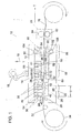
- FIG. 1 A preferred embodiment of a stretch-forming press 10 in accordance with the present invention is shown in FIG. 1.
- Press 10 includes a progressive tool 12 having a ram 14 that is stroked by the action of a crankshaft 16, cycling progressive tool 12 between an open condition and a closed condition.
- the stroke 18 of the ram 14 results in a known open height and shut height of ram 14 when progressive tool 12 is in its open and closed conditions, respectively.
- Progressive tool 12 is comprised of three stations and a roll feeding mechanism 20 that advances a coil of sheet metal through the progressive tool.
- a pre-forming station 22 has a pair of spaced apart dies 24, 26 that will stretch-form two alignment recesses such as channels 28 (seen in FIG. 2) in a central portion of a sheet metal strip 32 provided from an input coil 34.
- Sheet metal strip 32 may be formed of any material having elastic properties that result in snap-back when the material of sheet metal strip 32 is stretch-formed.
- the material of sheet metal strip 32 may be, e.g., 310 stainless steel, 316 stainless steel, titanium, aluminum, nickel 200, etc.
- Die 24 is surrounded by a jaw 36 and has a projection such as a rib 40 formed on its end Projection 40 is received by a recess such as a groove 42 formed in a base member 44 of progressive tool 12 that is positioned on the opposite side of sheet metal strip 32 from die 24.
- die 26 is surrounded by a jaw 46 and has a projection such as a rib 50 formed on its end Projection 50 is received by a recess such as a groove 52 formed in base member 44.
- Jaws 36, 46 are biased by corresponding biasing members 54, 56, respectively, into engagement with base member 44, thereby tightly gripping sheet metal strip 32 between jaws 36, 46 and base member 44, and preventing the draw-in of sheet metal strip 32 when progressive tool 12 is closed.
- biasing members 54, 56 are urethane rubber pads. Biasing members 54, 56 may be springs or any other suitable resilient member that will bias jaws 36, 46 into engagement with base member 44.
- sheet metal strip 32 is grasped tightly between jaws 36, 46 and base member 44.
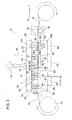
- dies 24, 26 are pressed into engagement with corresponding grooves 42, 52, respectively, stretch-forming channels 28 into sheet metal strip 32, as seen in FIG. 3. Since sheet metal strip 32 is grasped tightly between jaws 36, 46 and base member 44, no material is drawn into the stretch-formed regions of the sheet metal strip 32 from beyond jaws 36, 46. This prevents the non stretch-formed areas of the sheet metal strip 32 from being distorted.
- Dies 24, 26 and, therefore, channels 28, are spaced apart a distance D from one another, which is referred to as the pitch of the stamping being formed, as described in greater detail below.
- progressive tool 12 is opened, and sheet metal strip 32 is advanced in a direction of travel T through progressive tool 12.
- sheet metal strip 32 is advanced by feed mechanism 20 the distance D such that the trailing channel 28 of the two channels 28 formed at pre-fonning station 22 is aligned with die 26.
- a series of channels 28, each spaced a distance D from one another can be formed, allowing a continuously stamped sheet metal strip to be formed.
- a main forming station 58 is positioned downstream, with respect to the direction of travel T, of pre-forming station 22.
- Forming station 58 includes a die 59 and a pair of jaws 60, preferably spaced apart by distance D.
- jaws 60 include projections such as ribs 62 on ends thereof, which cooperate with recesses such as grooves 64 formed in base member 44 to grasp channels 28 of sheet metal strip 32 as progressive tool 12 closes.
- Die 59 also includes a pattern such as a plurality of ribs 66 and grooves 68 positioned between jaws 60, which mate with a corresponding pattern such as ribs 70 and grooves 72 formed in base member 44.
- Jaws 60 are biased by biasing members 61 into engagement with base member 44, thereby tightly gripping sheet metal strip 32 between jaws 60 and base member 44.
- biasing members 61 are urethane rubber pads. Biasing members 61 may be springs or any other suitable resilient member that will bias jaws 60 into engagement with base member 44. Since sheet metal strip 32 is grasped tightly between jaws 60 and base member 44, no material is drawn into the stretch-formed regions of the sheet metal strip 32 from beyond jaws 60.
- sheet metal strip 32 is grasped tightly between jaws 60 and base member 44.
- ribs 66 are received in corresponding grooves 72, and, similarly, ribs 70 are received in corresponding grooves 68, thereby stretch-forming a plurality of channels 74 into sheet metal strip 32 between the two pre-formed channels 28.
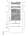
- the additional channels 74 and the pre-formed channels 28 together comprise a stamping 76, as seen in FIG. 2.
- Ribs 66, 70 and grooves 68, 72 of dies 59, 61, respectively, are configured such that stamping 76 is applied only to the central portion of the sheet metal strip 32. Consequently, edge portions 78, 80 of sheet metal strip 32 are free of any channels or other stampings.
- auxiliary jaws with corresponding biasing members may be provided in main forming station 58, each auxiliary jaw extending along one of the peripheral edge portions 78, 80.
- the auxiliary jaws act to prevent the draw-in of material from edge portions 78, 80 when channels 74 are shetch-formed, and to maintain sheet metal strip 32 in proper position.
- the illustrated embodiment is directed to a stamping formed exclusively of channels, the present invention is not limited to such stampings, but, rather, is applicable to any desired pattern that can be stretch-formed into a strip of sheet metal.
- the reduction of distortion that the present invention provides is equally applicable to patterns having many different configurations, and any such configuration is considered to be within the scope of the present invention.
- stamping of a desired length may be created.
- sheet metal strip 32 may be advanced a distance greater than the distance D during an open cycle of the press, e.g., a multiple of the distance D in order to ensure uniformity of stamping 76, or a sufficient distance that stamping 76 is advanced beyond progressive tool 12. This will create a non-stretch-formed area 77 in sheet metal strip 32, which will be equal in length to the distance the sheet is advanced during the open cycle.
- Non-stretch-formed area 77 provides an area where sheet metal strip 32 can be cut, thereby providing a stamped sheet metal plate of a desired length.
- sheet metal strip 32 is advanced the distance 2xD to create non-stretch-formed area 77.
- a separate pre-forming station 22 upstream of main forming station 58, it is possible to intermittently advance the sheet metal strip 32 a distance of 2xD (or any other multiple of D) to provide a non-stamped section of the sheet metal strip 32 that can be utilized to receive a cut.
- This non-stamped section can, in certain preferred embodiments, be folded over end caps onto leading and trailing ends of adjacent bipolar plates in the manufacture of electrochemical fuel cells.
- Feed mechanism 20 serves to advance sheet metal strip 32 through progressive tool 12.
- feed mechanism 20 is a roll feed mechanism and includes a lower roll 82 and an upper roll 84 that are driven by a motor (not shown) to pull sheet metal strip 32 the desired distance when progressive tool 12 is in its open condition, as seen in FIG. 1.
- a feed mechanism may be configured to push sheet metal strip 32 through progressive tool 12. Pulling sheet metal through progressive tool 12 with feed mechanism 20 is a preferred embodiment when sheet metal strip 32 is thin and cannot be pushed through progressive tool 12.
- Lower roll 82 is relieved in the area where stamping 76 of sheet metal strip 32 passes between lower roll 82 and upper roll 84, as can be seen in FIG. 2, in order to prevent damage to stamping 76 as sheet metal strip 32 is advanced.
- lower roll 82 engages only the edge portions 78, 80 of sheet metal strip 32 as it cooperates with upper roll 84 to pull sheet metal strip 32 through progressive tool 12.
- a leveling station 86 is positioned downstream, with respect to the direction of travel T, of forming station 58, and serves to reduce distortion created in sheet metal strip 32 at forming station 58 when stamping 76 is created.
- Leveling station 86 includes a pair of jaws 88 and 90, which are positioned on opposite sides of sheet metal strip 32.
- Jaw 88 is slidably received in a recess 92 formed in a jaw housing 94.
- Jaw 88 has a projection such as a rib 98 on one end thereof that is configured to mate with a corresponding channel 28 of sheet metal strip 32.
- Jaw 90 is slidably received in a recess 102 formed in base member 44.
- Jaw 90 has a recess such as a groove 108 on one end thereof configured to mate with a the corresponding channel 28 of sheet metal strip 32 when progressive tool 12 is closed, such that jaws 88, 90 cooperate to tightly grasp sheet metal strip 32.
- Jaws 88, 90 are biased by biasing members 104, 106, respectively, into engagement with each other, thereby tightly gripping sheet metal strip 32 between them.
- biasing members 104, 106 are urethane rubber pads.
- Biasing members 104, 106 may be springs or any other suitable resilient member that will bias jaws 88, 90 into engagement with each other.
- sheet metal strip 32 is advanced through progressive tool 12 to leveling station 86 by feed mechanism 20 the distance D such that rib 98 of jaw 88 and groove 108 of jaw 90 are properly aligned with a corresponding channel 28.
- progressive tool 12 starts to close, jaws 88, 90 tightly grasp sheet metal strip 32 along the corresponding channel 28.
- progressive tool 12 is at a position of initial contact with sheet metal strip 32.
- the distance L between the most downstream jaw 60 of forming station 58 and jaws 88, 90 of leveling station 86 is equal to the distance D less the snap-back distance of the sheet metal that is, the pitch of stamping 76 less the snap-back distance.
- jaws 88, 90 retract into corresponding recesses 92, 102, respectively, to the position illustrated in FIG. 5, where ram 14 is shown in its lowest position and progressive tool 12 is shown being completely closed.
- Recesses 92, 102 are configured such that a centerline of travel 110 of each of jaws 88, 90 is at an acute angle 112 with respect to the direction of travel T of sheet metal strip 32.
- the movement of each of jaws 88, 90 consists of both a vertical and horizontal component. More specifically, jaws 88, 90 move both in a perpendicular direction, that is, in a direction substantially perpendicular to the direction of travel T of sheet metal strip 32 (vertically as seen in the illustrated embodiment of FIG.
- jaws 88, 90 are spaced a distance L' from the most downstream jaw 60 of forming station 58, which is a distance greater than the distance L.
- the lateral motion of jaws 88, 90 at the pre-formed channel 8 has the effect of stretching stamping 76 in the direction of travel T of sheet metal strip 32, resulting in an over-pull of stamping 76.
- each of pre-forming station 22, main forming station 58 and leveling station 86 release stamping 76, and the over-pull produced by jaws 88, 90 in leveling station 86 snaps back an amount necessary to eliminate the residual stress of stamping 76 relative to the un-stamped peripheral edge portions 78, 80.
- Angle 112 is sized such that jaws 88, 90 stretch sheet metal strip 32 an amount capable of countering effects of snap-back that result from stamping the desired pattern.
Landscapes
- Engineering & Computer Science (AREA)
- Mechanical Engineering (AREA)
- Shaping Metal By Deep-Drawing, Or The Like (AREA)
- Press Drives And Press Lines (AREA)
- Forging (AREA)
- Superconductors And Manufacturing Methods Therefor (AREA)
- Vehicle Body Suspensions (AREA)
Abstract
Description
- This invention relates to sheet metal stampings formed by progressive stamping tools and, more particularly, to a method and apparatus for the leveling of stamped sheet metal to remove or avoid unwanted distortions according to the preambles of
claim 1 and claim 11 respectively (see US-B 6 408 670). - Sheet metal is a common material used in mass-production manufacturing. Progressive tooling is often used to mass-produce items from a coil of sheet metal by passing the sheet metal through a tool or series of tools, e.g., a stamping press or stretch-forming press, that progressively shape and form the item being produced. Precise control of the feeding distance (or pitch) of the tool that performs the stamping, the feeding rate of the coil of sheet metal, and the frequency (open and shut frequency of the press determined by crankshaft RPM) is required.
- In instances where the finished product is punched out of the coil and collected in a bin, such as in the case of circular or semi-spherical metal shells, the remaining portion of the coil of sheet metal is recycled as scrap. In these instances, pilot holes may be punched into the coil in areas of the coil adjacent to the areas being worked by the tooling. The pilot holes may be used to guide and regulate the feeding of the coil through the progressive tooling. In other instances, for example, in the manufacture of bipolar plates for electrochemical fuel cells, the finished product is the stamped coil itself. These coils are typically fed through a stretch-forming press by rollers.
- Stretch-forming is a sheet metal forming process that is well known and that has been applied to numerous sheet metal products, for example, to the production of bipolar plates for fuel cells as described in commonly owned U.S. patent application number 09/714,526, entitled Fuel Cell Bipolar Separator Plate and Current Collector Assembly and Method of Manufacture, filed on November 16, 2000.
- Stretch-forming is performed in a manner that prevents the drawing-in of adjacent sheet metal into the tooling as the stretch-forming is performed. In the area where the sheet metal is stretched to its desired form, it is elongated well beyond the yield point of the material. Upon opening of the stretch-forming tool, the sheet metal will undergo spring- back or snap-back to relieve residual stress in the sheet metal. The amount of snap-back may be as much as several thousandths of an inch per inch, depending on the mechanical properties of the sheet metal.
- In certain cases, peripheral areas of the sheet metal are not stretch-formed by the tooling. For example, when producing continuous components, such as bipolar plates for fuel cells, peripheral edge portions of the sheet metal coil are not stretch-formed and are subsequently processed to operate as seal areas. As the sheet metal coil is progressively stretch-formed as it passes through a stretch-forming press, the snap-back of sheet metal will accumulate as the coil progresses through the press and, therefore, will distort the coil. Effectively, the center area of the coil that is stretch-formed becomes shorter than the adjacent edge portions of the coil that are not stretch-formed. This accumulated distortion creates problems when feeding the coil with coil feeding equipment such as roll feeds, which are used when the use of pilot holes is an impractical method of guiding and regulating the feeding of the coil. For example, pilot holes may be impractical when the material is too thin, or the end product otherwise results in an inability to punch pilot holes in the coil of material.
- A need exists for a method and apparatus that will avoid distortion of sheet metal coils that are processed by stretch-forming tooling in a progressive mode, and which use roll feed equipment to advance the coil.
- US-B6,408,670 describes how parts can be stamped and stretch-formed from a strip of sheet material, having a width that substantially corresponds to the width of the final part. To that end, the strip is fed along a liftable surface by means of common guiding means, wherein the liftable platform extends over and along a sequence of dies. Since no edge portions are formed, this method does not suffer from abovementioned problem of accumulated distortion in edge portions that were not stretch-formed.
- It is an object of the present invention to provide a method and apparatus that reduces or wholly overcomes some or all of the difficulties inherent in prior known devices. Particular objects and advantages of the invention will be apparent to those skilled in the art, that is, those who are knowledgeable or experienced in this field of technology, in view of the following disclosure of the invention and detailed description of certain preferred embodiments.
- In the present invention a means is provided to counter the effect of the snap-back of sheet metal that occurs as a stretch-form tool opens.
- In accordance with a first aspect, a method of reducing distortion in a stamped sheet metal strip includes the steps of providing a stretch-forming press having a main forming station and a leveling station, the leveling station having a pair of jaws, each jaw being slidably received in a recess inclined at an acute angle with respective to a direction of travel of a strip of sheet metal through the stretch-forming press; stamping a desired pattern on the strip of sheet metal at the main forming station by closing the stretch-fonning press; advancing the strip of sheet metal through the stretch-forming press in a direction of travel a desired distance such that the desired pattern is aligned with the leveling station; and closing the stretch-forming press such that the jaws of the leveling station engage the strip of sheet metal and stretch a portion of the strip of sheet metal containing the desired pattern in the direction of travel a selected distance as the jaws slide into the respective recesses when the stretch-forming press is closed.
- In accordance with a second aspect, a stretch-forming press for continuous feed sheet metal includes a ram, a base member, and a feed mechanism configured to advance a strip of sheet metal through the stretch-forming press. A forming station has a die configured to form a desired pattern in a strip of sheet metal. A leveling station has a pair of opposed jaws that are slidably received in corresponding recesses of the stretch-forming press. The jaws are oriented at an angle with respect to a direction of travel for a strip of sheet metal through the leveling station.
- In accordance with yet another aspect, a stretch-forming press for continuous feed sheet metal includes a ram, a base member, and a feed mechanism configured to advance a strip of sheet metal through the stretch-forming press. A pre-forming station has a pair of spaced apart dies configured to mate with recesses formed in the base member to form alignment recesses in a strip of sheet metal shaped in the stretch-fonning press. Each die is surrounded by a jaw, with each jaw biased toward the base member by a biasing member. A main forming station has a pair of spaced apart jaws configured to mate with alignment recesses formed in a strip of sheet metal at the pre-forming station. A die is configured to form a desired pattern in a strip of sheet metal passing through the stretch-forming press. A leveling station has a pair of opposed jaws slidably received in corresponding recesses of the stretch-forming press, and the jaws are oriented at an angle with respect to a direction of travel for a strip of sheet metal passing through the stretch-forming press.
- Substantial advantage is achieved through the present invention since distortion of the sheet metal is minimized. These and additional features and advantages of the invention disclosed here will be further understood from the following detailed disclosure of certain preferred embodiments.
- The aspects of the invention will become apparent upon reading the following detailed description in conjunction with the accompanying drawings, in which:
- FIG. 1 is a schematic elevation view of a stretch-forming press in accordance with a preferred embodiment of the present invention, shown in its open condition.
- FIG. 2 is a bottom view of a sheet metal strip formed in the stretch-forming press of FIG. 1, shown with the lower half of the tooling of the stretch-forming press removed, and showing the lower roll of the roll feed mechanism of the stretch-forming press.
- FIG. 3 is a schematic elevation view of the stretch-forming press of FIG. 1, shown in its closed condition.
- FIG. 4 is an enlarged elevation view of the leveling station of the stretch-forming press of FIG. 1, showing the jaws of the leveling station in their initial contact condition.
- FIG. 5 is an enlarged elevation view of the leveling station of the stretch-forming press of FIG. 1, showing the jaws of the leveling station in their closed, recessed condition.
- The figures referred to above are not drawn necessarily to scale and should be understood to present a representation of the invention, illustrative of the principles involved. Some features of apparatus depicted in the drawings have been enlarged or distorted relative to others to facilitate explanation and understanding. The same reference numbers are used in the drawings for similar or identical components and features shown in various alternative embodiments. Methods and apparatus for leveling progressively formed sheet metal as disclosed herein, will have configurations and components determined, in part, by the intended application and environment in which they are used.
- A preferred embodiment of a stretch-forming
press 10 in accordance with the present invention is shown in FIG. 1.Press 10 includes aprogressive tool 12 having aram 14 that is stroked by the action of acrankshaft 16, cyclingprogressive tool 12 between an open condition and a closed condition. Thestroke 18 of theram 14 results in a known open height and shut height ofram 14 whenprogressive tool 12 is in its open and closed conditions, respectively.Progressive tool 12 is comprised of three stations and aroll feeding mechanism 20 that advances a coil of sheet metal through the progressive tool. Apre-forming station 22 has a pair of spaced apart dies 24, 26 that will stretch-form two alignment recesses such as channels 28 (seen in FIG. 2) in a central portion of asheet metal strip 32 provided from aninput coil 34.Sheet metal strip 32 may be formed of any material having elastic properties that result in snap-back when the material ofsheet metal strip 32 is stretch-formed. In certain preferred embodiments, e.g., whensheet metal strip 32 is used to form bipolar plates as described above, the material ofsheet metal strip 32 may be, e.g., 310 stainless steel, 316 stainless steel, titanium, aluminum, nickel 200, etc. - Die 24 is surrounded by a
jaw 36 and has a projection such as arib 40 formed on itsend Projection 40 is received by a recess such as agroove 42 formed in abase member 44 ofprogressive tool 12 that is positioned on the opposite side ofsheet metal strip 32 from die 24. Similarly, die 26 is surrounded by ajaw 46 and has a projection such as arib 50 formed on itsend Projection 50 is received by a recess such as agroove 52 formed inbase member 44.Jaws corresponding biasing members base member 44, thereby tightly grippingsheet metal strip 32 betweenjaws base member 44, and preventing the draw-in ofsheet metal strip 32 whenprogressive tool 12 is closed. In a preferred embodiment, biasingmembers Biasing members jaws base member 44. - In operation, as
progressive tool 12 starts to close,sheet metal strip 32 is grasped tightly betweenjaws base member 44. Asprogressive tool 12 closes further, dies 24, 26 are pressed into engagement withcorresponding grooves channels 28 intosheet metal strip 32, as seen in FIG. 3. Sincesheet metal strip 32 is grasped tightly betweenjaws base member 44, no material is drawn into the stretch-formed regions of thesheet metal strip 32 from beyondjaws sheet metal strip 32 from being distorted. - Dies 24, 26 and, therefore,
channels 28, are spaced apart a distance D from one another, which is referred to as the pitch of the stamping being formed, as described in greater detail below. Afterchannels 28 have been stretched-formed,progressive tool 12 is opened, andsheet metal strip 32 is advanced in a direction of travel T throughprogressive tool 12. In certain preferred embodiments,sheet metal strip 32 is advanced byfeed mechanism 20 the distance D such that the trailingchannel 28 of the twochannels 28 formed atpre-fonning station 22 is aligned withdie 26. Thus, a series ofchannels 28, each spaced a distance D from one another, can be formed, allowing a continuously stamped sheet metal strip to be formed. - A main forming
station 58 is positioned downstream, with respect to the direction of travel T, ofpre-forming station 22. Formingstation 58 includes adie 59 and a pair ofjaws 60, preferably spaced apart by distance D. In a preferred embodiment,jaws 60 include projections such asribs 62 on ends thereof, which cooperate with recesses such as grooves 64 formed inbase member 44 to graspchannels 28 ofsheet metal strip 32 asprogressive tool 12 closes. Die 59 also includes a pattern such as a plurality ofribs 66 andgrooves 68 positioned betweenjaws 60, which mate with a corresponding pattern such asribs 70 andgrooves 72 formed inbase member 44. -
Jaws 60 are biased by biasingmembers 61 into engagement withbase member 44, thereby tightly grippingsheet metal strip 32 betweenjaws 60 andbase member 44. In a preferred embodiment, biasingmembers 61 are urethane rubber pads.Biasing members 61 may be springs or any other suitable resilient member that will biasjaws 60 into engagement withbase member 44. Sincesheet metal strip 32 is grasped tightly betweenjaws 60 andbase member 44, no material is drawn into the stretch-formed regions of thesheet metal strip 32 from beyondjaws 60. - As
progressive tool 12 begins to close,sheet metal strip 32 is grasped tightly betweenjaws 60 andbase member 44. Asprogressive tool 12 is closed further and die 59 is pressed into engagement withbase member 44,ribs 66 are received in correspondinggrooves 72, and, similarly,ribs 70 are received in correspondinggrooves 68, thereby stretch-forming a plurality ofchannels 74 intosheet metal strip 32 between the twopre-formed channels 28. - The
additional channels 74 and thepre-formed channels 28 together comprise a stamping 76, as seen in FIG. 2.Ribs grooves sheet metal strip 32. Consequently,edge portions sheet metal strip 32 are free of any channels or other stampings. - In certain preferred embodiments, auxiliary jaws with corresponding biasing members (not shown) may be provided in main forming
station 58, each auxiliary jaw extending along one of theperipheral edge portions edge portions channels 74 are shetch-formed, and to maintainsheet metal strip 32 in proper position. - It is to be appreciated that although the illustrated embodiment is directed to a stamping formed exclusively of channels, the present invention is not limited to such stampings, but, rather, is applicable to any desired pattern that can be stretch-formed into a strip of sheet metal. The reduction of distortion that the present invention provides is equally applicable to patterns having many different configurations, and any such configuration is considered to be within the scope of the present invention.
- This process of forming
channels 28, advancingsheet metal strip 32 the distance D, and formingchannels 74 is repeated continuously to form a sheet having a stamping 76 extending a desired distance alongsheet metal strip 32. In certain preferred embodiments, a stamping of a desired length may be created. To create a stamped sheet of a desired length,sheet metal strip 32 may be advanced a distance greater than the distance D during an open cycle of the press, e.g., a multiple of the distance D in order to ensure uniformity of stamping 76, or a sufficient distance that stamping 76 is advanced beyondprogressive tool 12. This will create a non-stretch-formedarea 77 insheet metal strip 32, which will be equal in length to the distance the sheet is advanced during the open cycle. Non-stretch-formedarea 77 provides an area wheresheet metal strip 32 can be cut, thereby providing a stamped sheet metal plate of a desired length. In certain preferred embodiments,sheet metal strip 32 is advanced the distance 2xD to create non-stretch-formedarea 77. By positioning a separatepre-forming station 22 upstream of main formingstation 58, it is possible to intermittently advance the sheet metal strip 32 a distance of 2xD (or any other multiple of D) to provide a non-stamped section of thesheet metal strip 32 that can be utilized to receive a cut. This non-stamped section can, in certain preferred embodiments, be folded over end caps onto leading and trailing ends of adjacent bipolar plates in the manufacture of electrochemical fuel cells. -
Feed mechanism 20 serves to advancesheet metal strip 32 throughprogressive tool 12. In certain preferred embodiments,feed mechanism 20 is a roll feed mechanism and includes alower roll 82 and anupper roll 84 that are driven by a motor (not shown) to pullsheet metal strip 32 the desired distance whenprogressive tool 12 is in its open condition, as seen in FIG. 1. In other embodiments, a feed mechanism may be configured to pushsheet metal strip 32 throughprogressive tool 12. Pulling sheet metal throughprogressive tool 12 withfeed mechanism 20 is a preferred embodiment whensheet metal strip 32 is thin and cannot be pushed throughprogressive tool 12. -
Lower roll 82 is relieved in the area where stamping 76 ofsheet metal strip 32 passes betweenlower roll 82 andupper roll 84, as can be seen in FIG. 2, in order to prevent damage to stamping 76 assheet metal strip 32 is advanced. Thus, in this embodiment,lower roll 82 engages only theedge portions sheet metal strip 32 as it cooperates withupper roll 84 to pullsheet metal strip 32 throughprogressive tool 12. - A leveling
station 86, seen more clearly in FIG. 4, is positioned downstream, with respect to the direction of travel T, of formingstation 58, and serves to reduce distortion created insheet metal strip 32 at formingstation 58 when stamping 76 is created. Levelingstation 86 includes a pair ofjaws sheet metal strip 32.Jaw 88 is slidably received in arecess 92 formed in ajaw housing 94.Jaw 88 has a projection such as arib 98 on one end thereof that is configured to mate with a correspondingchannel 28 ofsheet metal strip 32.Jaw 90 is slidably received in arecess 102 formed inbase member 44.Jaw 90 has a recess such as agroove 108 on one end thereof configured to mate with a the correspondingchannel 28 ofsheet metal strip 32 whenprogressive tool 12 is closed, such thatjaws sheet metal strip 32. -
Jaws members sheet metal strip 32 between them. In a preferred embodiment, biasingmembers members jaws - As noted above,
sheet metal strip 32 is advanced throughprogressive tool 12 to levelingstation 86 byfeed mechanism 20 the distance D such thatrib 98 ofjaw 88 and groove 108 ofjaw 90 are properly aligned with a correspondingchannel 28. Asprogressive tool 12 starts to close,jaws sheet metal strip 32 along the correspondingchannel 28. As illustrated in FIG. 4,progressive tool 12 is at a position of initial contact withsheet metal strip 32. At this point, the distance L between the mostdownstream jaw 60 of formingstation 58 andjaws station 86 is equal to the distance D less the snap-back distance of the sheet metal that is, the pitch of stamping 76 less the snap-back distance. - As
progressive tool 12 closes further,jaws corresponding recesses ram 14 is shown in its lowest position andprogressive tool 12 is shown being completely closed. -
Recesses travel 110 of each ofjaws acute angle 112 with respect to the direction of travel T ofsheet metal strip 32. Thus, asjaws angle 112 with respect to the direction of travel T ofsheet metal strip 32. Accordingly, the movement of each ofjaws jaws progressive tool 12 is in its fully closed position,jaws downstream jaw 60 of formingstation 58, which is a distance greater than the distance L. - The lateral motion of
jaws sheet metal strip 32, resulting in an over-pull of stamping 76. Whenprogressive tool 12 is opened, each ofpre-forming station 22, main formingstation 58 and levelingstation 86 release stamping 76, and the over-pull produced byjaws station 86 snaps back an amount necessary to eliminate the residual stress of stamping 76 relative to the un-stampedperipheral edge portions Angle 112 is sized such thatjaws sheet metal strip 32 an amount capable of countering effects of snap-back that result from stamping the desired pattern. By pulling and snapping back stamping 76, stress insheet metal strip 32 is effectively leveled, and processing ofsheet metal strip 32 may proceed in progressive continuous mode without accumulation of distortion and without roll feeding problems.
Claims (29)
- A method of reducing distortion in a stamped sheet metal strip (32) comprising the steps of:providing a stretch-forming press (10) having a main forming station (58) and a leveling station (86);stamping a desired pattern on the strip of sheet metal (32) at the main forming station (58) by closing the stretch-forming press (10);advancing the strip of sheet metal (32) through the stretch-forming press (10) in a direction of travel (T) over a desired distancecharacterized in that:said desired distance is such that the desired pattern is aligned with the leveling station (86); the leveling station (86) having a pair of jaws (88, 90), each jaw being slidably received in a recess (92, 102) inclined at an acute angle (112) with respect to the direction of travel (T) of the strip of sheet metal (32) through the stretch-forming press (10);furthermore including the step of closing the stretch-forming press (10) such that the jaws (88, 90) of the leveling station (86) engage the strip of sheet metal (32) and stretch a portion of the strip of sheet metal (32) containing the desired pattern in the direction of travel (T) a selected distance as the jaws (88, 90) slide into the respective recesses (92, 102) when the stretch-forming press (10) is closed.
- The method of claim 1, wherein the acute angle (112) and a resultant travel distance of the jaws (88, 90) along the recess (92, 102) are sized such that the selected distance is sufficient to counter effects of snap- back that result from stamping the desired pattern.
- The method of claim 1, wherein the desired pattern comprises a plurality of channels (74).
- The method of claim 1, further comprising the steps of:providing a pre-forming station (22) in the stretch-forming press (10) upstream, with respect to the direction of travel (T), of the main forming station (58); andstamping a pair of spaced apart channels (28) in the strip of sheet metal (32) at the pre-forming station (22).
- The method of claim 4, wherein the distance (D) between the spaced apart channels (28) is the same distance as the desired distance (D).
- The method of claim 4, wherein the step of stamping the spaced apart channels (28) is performed by a die (24, 26).
- The method of claim 6, wherein each die (24, 26) is surrounded by a jaw (36, 46) biased into engagement with a base member (44) of the stretch-forming press (10) by a urethane rubber pad.
- The method of claim 1, wherein the step of advancing the strip of sheet metal (32) is performed by a pair of rollers (82, 84).
- The method of claim 1, further comprising the steps of:opening the stretch-forming press (10);advancing the strip of sheet metal (32) through the stretch-forming press (10);repeating the steps of stamping a desired pattern, advancing the strip of sheet metal (32), closing the stretch-forming press (10), opening the stretch-forming press, and advancing the strip of sheet metal (32), a desired number of times to produce a strip of sheet metal (32) having the desired pattern stamped continuously along its length.
- The method of claim 9, further comprising the step of intermittently advancing the strip of sheet metal (32) through the stretch-forming press (10) a greater distance than that required to align the desired pattern with the leveling station (86) when advancing the sheet metal strip (32) from the main forming station (58) to the leveling station (86) in order to create a portion of the sheet metal strip (32) along its length free of the desired pattern.
- A stretch-forming press (10) for continuous feed sheet metal (32) comprising, in combination:a ram (14);a base member (44);a feed mechanism (20) configured to advance a strip of sheet metal (32) through the stretch-forming press (10),a forming station (58) having a die (59) configured to form a desired pattern in a strip of sheet metal (32), characterized in thata leveling station (86) is provided, having a pair of opposed jaws (88, 90) slidably received in corresponding recesses (92, 102) of the stretch-forming press (10), the jaws (88, 90) oriented at an angle (112) with respect to a direction of travel (T) for a strip of sheet metal (32) through the leveling station (86).
- The stretch-forming press (10) of claim 11, wherein the die (59) is configured to produce a plurality of channels (74) in a strip of sheet metal (32).
- The stretch-forming press (10) of claim 12, wherein each jaw (88, 90) of the forming station (58) is biased toward the other jaw by a biasing member (104, 106).
- The stretch-forming press (10) of claim 13, wherein each biasing member (104, 106) comprises a urethane rubber pad.
- The stretch-forming press (10) of claim 11, further comprising a pre-forming station (22) having a pair of dies (24, 26) configured to form a pair of alignment recesses (28) in the sheet metal strip (32).
- The stretch-forming press (10) of claim 15, wherein the alignment recesses (28) are channels.
- The stretch-forming press (10) of claim 15, wherein each of the dies (24, 26) of the pre-forming station (22) is surrounded by a jaw (36, 46).
- The stretch-forming press (10) of claim 17, wherein each jaw (36, 46) of the pre-forming station (22) is biased toward the base member (44) by a biasing member (54, 56).
- The stretch-forming press (10) of claim 18, wherein each biasing member (54, 56) of the pre-forming station (22) comprises a urethane rubber pad.
- The stretch-forming press (10) of claim 11, wherein one jaw (90) of the leveling station (86) is slidably received in a recess (102) of the base member (44) and the other jaw (88) of the leveling station (86) is slidably received in a recess (92) formed in a jaw housing (94).
- The stretch-forming press (10) of claim 11, wherein the angle (112) is sized such that the jaws (88, 90) will stretch a portion of a strip of stamped sheet metal (32) when the ram (14) closes on the base member (44) a distance sufficient to counter effects of snap-back that result from stamping a desired pattern on a strip of sheet metal (32) with the forming station (58).
- The stretch-forming press (10) of claim 11, furthermore comprising:a pre-forming station (22) having a pair of spaced apart dies (24, 26) configured to mate with recesses (42, 52) formed in the base member (44) to form alignment recesses (28) in the strip of sheet metal (32) shaped in the stretch-forming press (10), each die (24, 26) being surrounded by a jaw (36, 46), each jaw biased toward the base member (44) by a biasing member (54, 56);wherein the forming station (58) furthermore comprises a pair of spaced apart jaws (60) configured to mate with the alignment recesses (28) formed in the strip of sheet metal (32) at the pre-forming station (22), each of the spaced apart jaws (60) biased toward the base member (44) by a biasing member (61);and wherein the jaws (88, 90) of the leveling station (86) are biased toward the base member (44) by a biasing member (104, 106).
- The stretch-forming press (10) of claim 22, wherein the alignment recesses (28) are channels.
- The stretch-forming press (10) of claim 22, wherein each biasing member (54, 56; 61; 104, 106) of the pre-forming station (22), the main forming station (58) and the leveling station (86) is a urethane rubber pad.
- The stretch-forming press (10) of claim 22, wherein the dies (24, 26, 59) are configured to form a plurality of channels (28, 74) in a strip of sheet metal (32).
- The stretch-forming press (10) of claim 22, wherein the feed mechanism (20) comprises a pair of rollers (82, 84) configured to cooperate to grip a strip of sheet metal (32) and pull it through the stretch-forming press (10).
- The stretch-forming press (10) of claim 26, wherein one of the rollers (82) is relieved in a central portion thereof.
- The stretch-forming press (10) of claim 22, wherein one jaw (90) is slidably received in a recess (102) of the base member (44) and the other jaw (88) is slidably received in a recess (92) formed in a jaw housing (94).
- The stretch-forming press (10) of claim 22, wherein the angle (112) is sized such that the jaws (88, 90) will stretch a portion of a strip of stamped sheet metal (32) when the ram (14) closes on the base member (44) a distance sufficient to counter effects of snap-back that result from stamping a desired pattern on a strip of sheet metal with the forming station (58).
Applications Claiming Priority (3)
| Application Number | Priority Date | Filing Date | Title |
|---|---|---|---|
| US10/350,863 US6772617B1 (en) | 2003-01-24 | 2003-01-24 | Method and apparatus for in-situ leveling of progressively formed sheet metal |
| US350863 | 2003-01-24 | ||
| PCT/US2004/001156 WO2004067202A1 (en) | 2003-01-24 | 2004-01-16 | Method and apparatus for in-situ leveling of progressively formed sheet metal |
Publications (2)
| Publication Number | Publication Date |
|---|---|
| EP1585608A1 EP1585608A1 (en) | 2005-10-19 |
| EP1585608B1 true EP1585608B1 (en) | 2006-09-27 |
Family
ID=32735665
Family Applications (1)
| Application Number | Title | Priority Date | Filing Date |
|---|---|---|---|
| EP04702989A Expired - Lifetime EP1585608B1 (en) | 2003-01-24 | 2004-01-16 | Method and apparatus for in-situ leveling of progressively formed sheet metal |
Country Status (11)
| Country | Link |
|---|---|
| US (1) | US6772617B1 (en) |
| EP (1) | EP1585608B1 (en) |
| KR (1) | KR20050092043A (en) |
| CN (1) | CN100351026C (en) |
| AT (1) | ATE340660T1 (en) |
| BR (1) | BRPI0406728A (en) |
| CA (1) | CA2512245A1 (en) |
| DE (1) | DE602004002559T2 (en) |
| ES (1) | ES2274416T3 (en) |
| MX (1) | MXPA05007564A (en) |
| WO (1) | WO2004067202A1 (en) |
Families Citing this family (14)
| Publication number | Priority date | Publication date | Assignee | Title |
|---|---|---|---|---|
| EP1628789B1 (en) * | 2003-05-30 | 2008-07-16 | Emitec Gesellschaft für Emissionstechnologie mbH | Production of a structured sheet metal for devices for treating exhaust gas |
| JP4065832B2 (en) * | 2003-12-03 | 2008-03-26 | 本田技研工業株式会社 | Press forming apparatus and press forming method for metal separator for fuel cell |
| US20080199751A1 (en) * | 2007-02-20 | 2008-08-21 | Commonwealth Scientific And Industrial Research Organisation | Bipolar plate for an air breathing fuel cell stack |
| JP5383174B2 (en) * | 2008-12-19 | 2014-01-08 | 株式会社エフ・シー・シー | Sheet material bending machine |
| US20130343897A1 (en) * | 2012-06-21 | 2013-12-26 | David A. Collins | Helix Type Vertical Axis Turbine Blades and Method for Continuously Making Same |
| US10020519B2 (en) * | 2013-06-04 | 2018-07-10 | Nissan Motor Co., Ltd. | Molding method for removing separator distortion and molding device for removing separator distortion |
| KR20160136609A (en) * | 2015-05-20 | 2016-11-30 | 현대자동차주식회사 | Progressive die machine and prograssive forming method |
| US10239109B2 (en) * | 2016-03-01 | 2019-03-26 | Stolle Machinery Company, Llc | Shell system locating assembly for shells |
| CN106826020A (en) * | 2017-03-10 | 2017-06-13 | 无锡先导智能装备股份有限公司 | Welding prestressing mechanism |
| CN113245445B (en) * | 2021-05-25 | 2022-12-20 | 深圳市吉百顺科技有限公司 | A integrative equipment of stamping forming for inductance processing |
| CN114523023B (en) * | 2022-02-15 | 2025-01-17 | 河北光兴半导体技术有限公司 | Stamping system and stamping forming method for fuel cell single pole plate |
| DE102022114501B4 (en) * | 2022-06-09 | 2025-07-17 | Schaeffler Technologies AG & Co. KG | Tool device for producing a bipolar plate and method |
| CN117139478B (en) * | 2023-06-30 | 2024-09-06 | 西安咏空电子科技有限公司 | Lithium battery shell stamping production line |
| CN119702863B (en) * | 2024-12-04 | 2025-11-07 | 东莞市东众五金制品有限公司 | Continuous stamping die for aluminum alloy plate |
Family Cites Families (78)
| Publication number | Priority date | Publication date | Assignee | Title |
|---|---|---|---|---|
| CH168501A (en) * | 1932-12-21 | 1934-04-15 | Ver Deutsche Metallwerke Ag | Device for the production of flat metal webs with parallel and straight edges. |
| US2352442A (en) * | 1940-05-23 | 1944-06-27 | Loewy Eng Co Ltd | Straightening machine for metal bars |
| GB614186A (en) * | 1946-07-05 | 1948-12-10 | Bigwood Joshua & Son Ltd | Improvements in gripping devices for sheet metal stretching machines |
| US3430476A (en) * | 1966-11-14 | 1969-03-04 | American Cyanamid Co | Corrugating machine |
| US4175165A (en) | 1977-07-20 | 1979-11-20 | Engelhard Minerals & Chemicals Corporation | Fuel cell system utilizing ion exchange membranes and bipolar plates |
| US4233833A (en) * | 1978-06-05 | 1980-11-18 | United States Gypsum Company | Method for stretching sheet metal and structural members formed therefrom |
| IT1202757B (en) | 1978-07-10 | 1989-02-09 | Elche Ltd | BIPOLAR SEPTUM FOR ELECTROCHEMICAL CELLS |
| US4169917A (en) | 1978-07-10 | 1979-10-02 | Energy Research Corporation | Electrochemical cell and separator plate thereof |
| US4982593A (en) * | 1986-01-15 | 1991-01-08 | Washington Steel Corporation | Gripper means for stretcher leveler apparatus |
| US4476197A (en) | 1983-10-12 | 1984-10-09 | The United States Of America As Represented By The United States Department Of Energy | Integral manifolding structure for fuel cell core having parallel gas flow |
| US4510212A (en) | 1983-10-12 | 1985-04-09 | The United States Of America As Represented By The United States Department Of Energy | Solid oxide fuel cell having compound cross flow gas patterns |
| JPS60253170A (en) | 1984-05-29 | 1985-12-13 | Ishikawajima Harima Heavy Ind Co Ltd | stacked fuel cell |
| US4604331A (en) | 1984-05-29 | 1986-08-05 | The United States Of America As Represented By The United States Department Of Energy | Fuel cell separator plate with bellows-type sealing flanges |
| JPH0736334B2 (en) | 1984-07-13 | 1995-04-19 | 三菱電機株式会社 | Molten carbonate fuel cell electrode |
| US4548876A (en) | 1984-10-17 | 1985-10-22 | The United States Of America As Represented By The United States Department Of Energy | Integrated current collector and catalyst support |
| US4751838A (en) * | 1985-11-18 | 1988-06-21 | Red Bud Industries, Inc. | Machine and process for leveling sheet metal strip |
| US4631239A (en) | 1985-12-04 | 1986-12-23 | Westinghouse Electric Corp. | Fuel cell plates with improved arrangement of process channels for enhanced pressure drop across the plates |
| US4853301A (en) | 1985-12-04 | 1989-08-01 | The United States Of America As Represented By The United States Department Of Energy | Fuel cell plates with skewed process channels for uniform distribution of stack compression load |
| JPH0626126B2 (en) | 1986-06-13 | 1994-04-06 | 株式会社日立製作所 | Fuel cell |
| US4702973A (en) | 1986-08-25 | 1987-10-27 | Institute Of Gas Technology | Dual compartment anode structure |
| JP2569550B2 (en) | 1987-05-08 | 1997-01-08 | 石川島播磨重工業株式会社 | Fuel cell temperature distribution improvement method |
| US4857420A (en) | 1987-10-13 | 1989-08-15 | International Fuel Cell Corporation | Method of making monolithic solid oxide fuel cell stack |
| US5227256A (en) | 1989-05-03 | 1993-07-13 | Institute Of Gas Technology | Fully internal manifolded fuel cell stack |
| NL8901800A (en) | 1989-07-12 | 1991-02-01 | Stichting Energie | SEPARATOR PLATE FOR APPLICATION IN A GAS FUEL CELL, INCLUDING A COLLECTION OF ELECTRODES, AND STACKING OF FUEL CELLS. |
| US4983472A (en) | 1989-11-24 | 1991-01-08 | International Fuel Cells Corporation | Fuel cell current collector |
| DE4206490C2 (en) | 1992-03-02 | 1994-03-10 | Fraunhofer Ges Forschung | Electrically conductive gas distribution structure for a fuel cell and method for its production |
| US5298342A (en) | 1992-10-20 | 1994-03-29 | M-C Power Corporation | Fuel cell crossover arrestor and pressure seal |
| US5362578A (en) | 1992-12-08 | 1994-11-08 | Institute Of Gas Technology | Integrated main rail, feed rail, and current collector |
| IT1270878B (en) | 1993-04-30 | 1997-05-13 | Permelec Spa Nora | IMPROVED ELECTROCHEMISTRY CELL USING ION EXCHANGE MEMBRANES AND METAL BIPOLAR PLATES |
| JP2948441B2 (en) | 1993-06-29 | 1999-09-13 | 三洋電機株式会社 | Flat solid electrolyte fuel cell |
| US5424144A (en) | 1993-10-21 | 1995-06-13 | M-C Power Corporation | One piece separator plate with insert ring step design |
| US5527363A (en) | 1993-12-10 | 1996-06-18 | Ballard Power Systems Inc. | Method of fabricating an embossed fluid flow field plate |
| US5460897A (en) | 1994-03-18 | 1995-10-24 | Allied Signal Inc. | Solid oxide fuel cell stacking assembly |
| ATE189560T1 (en) | 1994-03-21 | 2000-02-15 | Ztek Corp | ELECTROCHEMICAL CONVERTER WITH OPTIMAL PRESSURE DISTRIBUTION |
| DE4410711C1 (en) | 1994-03-28 | 1995-09-07 | Forschungszentrum Juelich Gmbh | Metallic bipolar plate for HT fuel cells and method of manufacturing the same |
| DE69514567T2 (en) | 1994-05-20 | 2000-08-31 | Clc S.R.L., Genua/Genova | Cooling plate assembly for a fuel cell stack |
| US5773160A (en) | 1994-06-24 | 1998-06-30 | Ballard Power Systems Inc. | Electrochemical fuel cell stack with concurrent flow of coolant and oxidant streams and countercurrent flow of fuel and oxidant streams |
| US5558955A (en) | 1994-10-07 | 1996-09-24 | International Fuel Cells Corporation | Cathode reactant flow field component for a fuel cell stack |
| RU2174728C2 (en) | 1994-10-12 | 2001-10-10 | Х Пауэр Корпорейшн | Fuel cell using integrated plate technology for liquid-distribution |
| US5863671A (en) | 1994-10-12 | 1999-01-26 | H Power Corporation | Plastic platelet fuel cells employing integrated fluid management |
| JPH10510664A (en) | 1994-12-17 | 1998-10-13 | ラフバロウ ユニヴァーシティ イノヴェイションズ リミテッド | Structure of electrolyte fuel cell |
| AUPN173595A0 (en) | 1995-03-15 | 1995-04-06 | Ceramic Fuel Cells Limited | Fuel cell interconnect device |
| US5726105A (en) | 1995-04-20 | 1998-03-10 | International Fuel Cells | Composite article |
| DE19547700C2 (en) | 1995-12-20 | 1998-09-17 | Forschungszentrum Juelich Gmbh | Electrode substrate for a fuel cell |
| DE19602315C2 (en) | 1996-01-23 | 2001-10-11 | Siemens Ag | Liquid-cooled fuel cell with distribution channels |
| JP3540491B2 (en) | 1996-03-07 | 2004-07-07 | 政廣 渡辺 | Fuel cell, electrolytic cell and cooling / dehumidifying method thereof |
| US6054228A (en) | 1996-06-06 | 2000-04-25 | Lynntech, Inc. | Fuel cell system for low pressure operation |
| JP3499090B2 (en) | 1996-08-07 | 2004-02-23 | 本田技研工業株式会社 | Fuel cell |
| US5795665A (en) | 1996-08-19 | 1998-08-18 | Energy Research Corporation | Fuel cell sub-assembly with a plurality of dimples |
| US5798187A (en) | 1996-09-27 | 1998-08-25 | The Regents Of The University Of California | Fuel cell with metal screen flow-field |
| US5773161A (en) | 1996-10-02 | 1998-06-30 | Energy Research Corporation | Bipolar separator |
| US6037073A (en) | 1996-10-15 | 2000-03-14 | Lockheed Martin Energy Research Corporation | Bipolar plate/diffuser for a proton exchange membrane fuel cell |
| JPH10125338A (en) | 1996-10-22 | 1998-05-15 | Fuji Electric Co Ltd | Solid polymer electrolyte fuel cell |
| AU7181998A (en) | 1996-11-14 | 1998-06-03 | Dais Corporation | Fuel cell stack assembly |
| US5707755A (en) | 1996-12-09 | 1998-01-13 | General Motors Corporation | PEM/SPE fuel cell |
| US5776624A (en) | 1996-12-23 | 1998-07-07 | General Motors Corporation | Brazed bipolar plates for PEM fuel cells |
| JP3077618B2 (en) | 1997-03-05 | 2000-08-14 | 富士電機株式会社 | Solid polymer electrolyte fuel cell |
| FR2764443B1 (en) | 1997-06-10 | 1999-09-03 | Peugeot | FUEL CELL OF THE TYPE WITH PLATE-SHAPED REAGENT DISPENSERS |
| US6048634A (en) | 1997-06-18 | 2000-04-11 | H Power Corporation | Fuel cell using water-soluble fuel |
| US5798188A (en) | 1997-06-25 | 1998-08-25 | E. I. Dupont De Nemours And Company | Polymer electrolyte membrane fuel cell with bipolar plate having molded polymer projections |
| JP3775618B2 (en) | 1997-06-30 | 2006-05-17 | アイシン精機株式会社 | Fuel cell |
| US5811202A (en) | 1997-08-05 | 1998-09-22 | M-C Power Corporation | Hybrid molten carbonate fuel cell with unique sealing |
| US5770327A (en) | 1997-08-15 | 1998-06-23 | Northwestern University | Solid oxide fuel cell stack |
| DE19735854C2 (en) | 1997-08-19 | 2002-08-01 | Daimler Chrysler Ag | Current collector for a fuel cell and method for its production |
| US6033794A (en) | 1997-12-10 | 2000-03-07 | The United States Of America As Represented By The United States Department Of Energy | Multi-stage fuel cell system method and apparatus |
| US6099984A (en) | 1997-12-15 | 2000-08-08 | General Motors Corporation | Mirrored serpentine flow channels for fuel cell |
| US6051330A (en) | 1998-01-15 | 2000-04-18 | International Business Machines Corporation | Solid oxide fuel cell having vias and a composite interconnect |
| US6096450A (en) | 1998-02-11 | 2000-08-01 | Plug Power Inc. | Fuel cell assembly fluid flow plate having conductive fibers and rigidizing material therein |
| JP4873780B2 (en) | 1998-02-27 | 2012-02-08 | コーニング インコーポレイテッド | Flexible inorganic electrolyte fuel cell structure |
| JP4205774B2 (en) | 1998-03-02 | 2009-01-07 | 本田技研工業株式会社 | Fuel cell |
| US6040076A (en) | 1998-03-03 | 2000-03-21 | M-C Power Corporation | One piece fuel cell separator plate |
| US6071635A (en) | 1998-04-03 | 2000-06-06 | Plug Power, L.L.C. | Easily-formable fuel cell assembly fluid flow plate having conductivity and increased non-conductive material |
| US6074692A (en) | 1998-04-10 | 2000-06-13 | General Motors Corporation | Method of making MEA for PEM/SPE fuel cell |
| DE19821767C2 (en) | 1998-05-14 | 2000-06-08 | Siemens Ag | Liquid cooling fuel cell stack and method for cooling a FC stack |
| US6054231A (en) | 1998-07-24 | 2000-04-25 | Gas Research Institute | Solid oxide fuel cell interconnector |
| US6261710B1 (en) | 1998-11-25 | 2001-07-17 | Institute Of Gas Technology | Sheet metal bipolar plate design for polymer electrolyte membrane fuel cells |
| US6408670B1 (en) * | 1999-08-25 | 2002-06-25 | George Trapp | Carrierless progressive die system |
| JP4476463B2 (en) | 2000-09-26 | 2010-06-09 | 本田技研工業株式会社 | Fuel cell separator and fuel cell |
-
2003
- 2003-01-24 US US10/350,863 patent/US6772617B1/en not_active Expired - Fee Related
-
2004
- 2004-01-16 CN CNB2004800022043A patent/CN100351026C/en not_active Expired - Fee Related
- 2004-01-16 KR KR1020057013016A patent/KR20050092043A/en not_active Ceased
- 2004-01-16 AT AT04702989T patent/ATE340660T1/en not_active IP Right Cessation
- 2004-01-16 MX MXPA05007564A patent/MXPA05007564A/en active IP Right Grant
- 2004-01-16 CA CA002512245A patent/CA2512245A1/en not_active Abandoned
- 2004-01-16 WO PCT/US2004/001156 patent/WO2004067202A1/en not_active Ceased
- 2004-01-16 DE DE602004002559T patent/DE602004002559T2/en not_active Expired - Fee Related
- 2004-01-16 BR BR0406728-2A patent/BRPI0406728A/en not_active IP Right Cessation
- 2004-01-16 EP EP04702989A patent/EP1585608B1/en not_active Expired - Lifetime
- 2004-01-16 ES ES04702989T patent/ES2274416T3/en not_active Expired - Lifetime
Also Published As
| Publication number | Publication date |
|---|---|
| CN100351026C (en) | 2007-11-28 |
| DE602004002559D1 (en) | 2006-11-09 |
| ES2274416T3 (en) | 2007-05-16 |
| BRPI0406728A (en) | 2005-12-20 |
| EP1585608A1 (en) | 2005-10-19 |
| WO2004067202A1 (en) | 2004-08-12 |
| KR20050092043A (en) | 2005-09-16 |
| ATE340660T1 (en) | 2006-10-15 |
| CN1738690A (en) | 2006-02-22 |
| CA2512245A1 (en) | 2004-08-12 |
| US6772617B1 (en) | 2004-08-10 |
| MXPA05007564A (en) | 2005-09-21 |
| US20040144151A1 (en) | 2004-07-29 |
| DE602004002559T2 (en) | 2007-06-21 |
| HK1086786A1 (en) | 2006-09-29 |
Similar Documents
| Publication | Publication Date | Title |
|---|---|---|
| EP1585608B1 (en) | Method and apparatus for in-situ leveling of progressively formed sheet metal | |
| AU664917B2 (en) | Two stage die set | |
| DE2928664A1 (en) | PUNCHING PRESS AND METHOD FOR THE PRODUCTION OF SEALED CAN FLOORS | |
| CN109759523A (en) | A kind of online cutting-off method in frame crossbeam abnormal shape end | |
| KR101637964B1 (en) | Corrugated fin manufacturing apparatus | |
| CN108356144A (en) | A kind of process for stamping and mold for air bag substrate production | |
| CN215467411U (en) | Rotary cutting die for sleeve for automobile chassis | |
| CN214417454U (en) | Side flanging double-acting mechanism of automobile body-in-white progressive die | |
| JPH09150224A (en) | Sheet metal press forming method and forming device | |
| CN210059459U (en) | Punching machine with guiding device | |
| EP1946862A1 (en) | Method of manufacturing ring-shaped member | |
| CN215279479U (en) | Double-bending progressive die for high-strength steel plate | |
| HK1086786B (en) | Method and apparatus for in-situ leveling of progressively formed sheet metal | |
| US9827606B2 (en) | Stamping apparatus having flared bead | |
| KR200326204Y1 (en) | Metal mold for a bended keeper of cap and a progressive mold apparatus in where the said metal mold is applied | |
| KR20210017804A (en) | Press machine | |
| DE102022114501B4 (en) | Tool device for producing a bipolar plate and method | |
| CN220029345U (en) | Stamping and shearing integrated processing equipment | |
| CN218475874U (en) | Precision folding semicircle application progressive die | |
| CN218574741U (en) | Inner and outer slide block shaping device | |
| CN121402488A (en) | Method and press for introducing deformed patterns in a sheet | |
| US6079308A (en) | Apparatus for sheet-metal plate processing to be employed at inclined C-frame presses | |
| CN215090180U (en) | Stamping die structure for stamping Z-shaped profile | |
| CN210648108U (en) | Processing die for clutch wave-shaped spring piece | |
| JPS61229418A (en) | Straightening method for bandlike material plate |
Legal Events
| Date | Code | Title | Description |
|---|---|---|---|
| PUAI | Public reference made under article 153(3) epc to a published international application that has entered the european phase |
Free format text: ORIGINAL CODE: 0009012 |
|
| 17P | Request for examination filed |
Effective date: 20050714 |
|
| AK | Designated contracting states |
Kind code of ref document: A1 Designated state(s): AT BE BG CH CY CZ DE DK EE ES FI FR GB GR HU IE IT LI LU MC NL PT RO SE SI SK TR |
|
| AX | Request for extension of the european patent |
Extension state: AL LT LV MK |
|
| GRAP | Despatch of communication of intention to grant a patent |
Free format text: ORIGINAL CODE: EPIDOSNIGR1 |
|
| DAX | Request for extension of the european patent (deleted) | ||
| GRAS | Grant fee paid |
Free format text: ORIGINAL CODE: EPIDOSNIGR3 |
|
| GRAA | (expected) grant |
Free format text: ORIGINAL CODE: 0009210 |
|
| AK | Designated contracting states |
Kind code of ref document: B1 Designated state(s): AT BE BG CH CY CZ DE DK EE ES FI FR GB GR HU IE IT LI LU MC NL PT RO SE SI SK TR |
|
| PG25 | Lapsed in a contracting state [announced via postgrant information from national office to epo] |
Ref country code: IT Free format text: LAPSE BECAUSE OF FAILURE TO SUBMIT A TRANSLATION OF THE DESCRIPTION OR TO PAY THE FEE WITHIN THE PRESCRIBED TIME-LIMIT;WARNING: LAPSES OF ITALIAN PATENTS WITH EFFECTIVE DATE BEFORE 2007 MAY HAVE OCCURRED AT ANY TIME BEFORE 2007. THE CORRECT EFFECTIVE DATE MAY BE DIFFERENT FROM THE ONE RECORDED. Effective date: 20060927 Ref country code: AT Free format text: LAPSE BECAUSE OF FAILURE TO SUBMIT A TRANSLATION OF THE DESCRIPTION OR TO PAY THE FEE WITHIN THE PRESCRIBED TIME-LIMIT Effective date: 20060927 Ref country code: SI Free format text: LAPSE BECAUSE OF FAILURE TO SUBMIT A TRANSLATION OF THE DESCRIPTION OR TO PAY THE FEE WITHIN THE PRESCRIBED TIME-LIMIT Effective date: 20060927 Ref country code: SK Free format text: LAPSE BECAUSE OF FAILURE TO SUBMIT A TRANSLATION OF THE DESCRIPTION OR TO PAY THE FEE WITHIN THE PRESCRIBED TIME-LIMIT Effective date: 20060927 Ref country code: CZ Free format text: LAPSE BECAUSE OF FAILURE TO SUBMIT A TRANSLATION OF THE DESCRIPTION OR TO PAY THE FEE WITHIN THE PRESCRIBED TIME-LIMIT Effective date: 20060927 Ref country code: BE Free format text: LAPSE BECAUSE OF FAILURE TO SUBMIT A TRANSLATION OF THE DESCRIPTION OR TO PAY THE FEE WITHIN THE PRESCRIBED TIME-LIMIT Effective date: 20060927 Ref country code: LI Free format text: LAPSE BECAUSE OF FAILURE TO SUBMIT A TRANSLATION OF THE DESCRIPTION OR TO PAY THE FEE WITHIN THE PRESCRIBED TIME-LIMIT Effective date: 20060927 Ref country code: FI Free format text: LAPSE BECAUSE OF FAILURE TO SUBMIT A TRANSLATION OF THE DESCRIPTION OR TO PAY THE FEE WITHIN THE PRESCRIBED TIME-LIMIT Effective date: 20060927 Ref country code: NL Free format text: LAPSE BECAUSE OF FAILURE TO SUBMIT A TRANSLATION OF THE DESCRIPTION OR TO PAY THE FEE WITHIN THE PRESCRIBED TIME-LIMIT Effective date: 20060927 Ref country code: RO Free format text: LAPSE BECAUSE OF FAILURE TO SUBMIT A TRANSLATION OF THE DESCRIPTION OR TO PAY THE FEE WITHIN THE PRESCRIBED TIME-LIMIT Effective date: 20060927 Ref country code: CH Free format text: LAPSE BECAUSE OF FAILURE TO SUBMIT A TRANSLATION OF THE DESCRIPTION OR TO PAY THE FEE WITHIN THE PRESCRIBED TIME-LIMIT Effective date: 20060927 |
|
| REG | Reference to a national code |
Ref country code: GB Ref legal event code: FG4D |
|
| REG | Reference to a national code |
Ref country code: CH Ref legal event code: EP |
|
| REG | Reference to a national code |
Ref country code: IE Ref legal event code: FG4D |
|
| REF | Corresponds to: |
Ref document number: 602004002559 Country of ref document: DE Date of ref document: 20061109 Kind code of ref document: P |
|
| PG25 | Lapsed in a contracting state [announced via postgrant information from national office to epo] |
Ref country code: BG Free format text: LAPSE BECAUSE OF FAILURE TO SUBMIT A TRANSLATION OF THE DESCRIPTION OR TO PAY THE FEE WITHIN THE PRESCRIBED TIME-LIMIT Effective date: 20061227 Ref country code: DK Free format text: LAPSE BECAUSE OF FAILURE TO SUBMIT A TRANSLATION OF THE DESCRIPTION OR TO PAY THE FEE WITHIN THE PRESCRIBED TIME-LIMIT Effective date: 20061227 Ref country code: SE Free format text: LAPSE BECAUSE OF FAILURE TO SUBMIT A TRANSLATION OF THE DESCRIPTION OR TO PAY THE FEE WITHIN THE PRESCRIBED TIME-LIMIT Effective date: 20061227 |
|
| PG25 | Lapsed in a contracting state [announced via postgrant information from national office to epo] |
Ref country code: IE Free format text: LAPSE BECAUSE OF NON-PAYMENT OF DUE FEES Effective date: 20070116 |
|
| PG25 | Lapsed in a contracting state [announced via postgrant information from national office to epo] |
Ref country code: MC Free format text: LAPSE BECAUSE OF NON-PAYMENT OF DUE FEES Effective date: 20070131 |
|
| NLV1 | Nl: lapsed or annulled due to failure to fulfill the requirements of art. 29p and 29m of the patents act | ||
| PG25 | Lapsed in a contracting state [announced via postgrant information from national office to epo] |
Ref country code: PT Free format text: LAPSE BECAUSE OF FAILURE TO SUBMIT A TRANSLATION OF THE DESCRIPTION OR TO PAY THE FEE WITHIN THE PRESCRIBED TIME-LIMIT Effective date: 20070313 |
|
| REG | Reference to a national code |
Ref country code: CH Ref legal event code: PL |
|
| REG | Reference to a national code |
Ref country code: ES Ref legal event code: FG2A Ref document number: 2274416 Country of ref document: ES Kind code of ref document: T3 |
|
| EN | Fr: translation not filed | ||
| PLBE | No opposition filed within time limit |
Free format text: ORIGINAL CODE: 0009261 |
|
| STAA | Information on the status of an ep patent application or granted ep patent |
Free format text: STATUS: NO OPPOSITION FILED WITHIN TIME LIMIT |
|
| 26N | No opposition filed |
Effective date: 20070628 |
|
| PG25 | Lapsed in a contracting state [announced via postgrant information from national office to epo] |
Ref country code: GR Free format text: LAPSE BECAUSE OF FAILURE TO SUBMIT A TRANSLATION OF THE DESCRIPTION OR TO PAY THE FEE WITHIN THE PRESCRIBED TIME-LIMIT Effective date: 20061228 Ref country code: FR Free format text: LAPSE BECAUSE OF FAILURE TO SUBMIT A TRANSLATION OF THE DESCRIPTION OR TO PAY THE FEE WITHIN THE PRESCRIBED TIME-LIMIT Effective date: 20070525 |
|
| PG25 | Lapsed in a contracting state [announced via postgrant information from national office to epo] |
Ref country code: EE Free format text: LAPSE BECAUSE OF FAILURE TO SUBMIT A TRANSLATION OF THE DESCRIPTION OR TO PAY THE FEE WITHIN THE PRESCRIBED TIME-LIMIT Effective date: 20060927 |
|
| PG25 | Lapsed in a contracting state [announced via postgrant information from national office to epo] |
Ref country code: FR Free format text: LAPSE BECAUSE OF FAILURE TO SUBMIT A TRANSLATION OF THE DESCRIPTION OR TO PAY THE FEE WITHIN THE PRESCRIBED TIME-LIMIT Effective date: 20060927 |
|
| PGFP | Annual fee paid to national office [announced via postgrant information from national office to epo] |
Ref country code: ES Payment date: 20090206 Year of fee payment: 6 |
|
| PGFP | Annual fee paid to national office [announced via postgrant information from national office to epo] |
Ref country code: DE Payment date: 20090212 Year of fee payment: 6 |
|
| PGFP | Annual fee paid to national office [announced via postgrant information from national office to epo] |
Ref country code: GB Payment date: 20090204 Year of fee payment: 6 |
|
| PG25 | Lapsed in a contracting state [announced via postgrant information from national office to epo] |
Ref country code: LU Free format text: LAPSE BECAUSE OF NON-PAYMENT OF DUE FEES Effective date: 20070116 Ref country code: CY Free format text: LAPSE BECAUSE OF FAILURE TO SUBMIT A TRANSLATION OF THE DESCRIPTION OR TO PAY THE FEE WITHIN THE PRESCRIBED TIME-LIMIT Effective date: 20060927 |
|
| PG25 | Lapsed in a contracting state [announced via postgrant information from national office to epo] |
Ref country code: HU Free format text: LAPSE BECAUSE OF FAILURE TO SUBMIT A TRANSLATION OF THE DESCRIPTION OR TO PAY THE FEE WITHIN THE PRESCRIBED TIME-LIMIT Effective date: 20070328 Ref country code: TR Free format text: LAPSE BECAUSE OF FAILURE TO SUBMIT A TRANSLATION OF THE DESCRIPTION OR TO PAY THE FEE WITHIN THE PRESCRIBED TIME-LIMIT Effective date: 20060927 |
|
| GBPC | Gb: european patent ceased through non-payment of renewal fee |
Effective date: 20100116 |
|
| PG25 | Lapsed in a contracting state [announced via postgrant information from national office to epo] |
Ref country code: DE Free format text: LAPSE BECAUSE OF NON-PAYMENT OF DUE FEES Effective date: 20100803 |
|
| PG25 | Lapsed in a contracting state [announced via postgrant information from national office to epo] |
Ref country code: GB Free format text: LAPSE BECAUSE OF NON-PAYMENT OF DUE FEES Effective date: 20100116 |
|
| REG | Reference to a national code |
Ref country code: ES Ref legal event code: FD2A Effective date: 20110325 |
|
| PG25 | Lapsed in a contracting state [announced via postgrant information from national office to epo] |
Ref country code: ES Free format text: LAPSE BECAUSE OF NON-PAYMENT OF DUE FEES Effective date: 20110314 |
|
| PGFP | Annual fee paid to national office [announced via postgrant information from national office to epo] |
Ref country code: IT Payment date: 20090202 Year of fee payment: 6 |
|
| PGRI | Patent reinstated in contracting state [announced from national office to epo] |
Ref country code: IT Effective date: 20110616 |
|
| PG25 | Lapsed in a contracting state [announced via postgrant information from national office to epo] |
Ref country code: ES Free format text: LAPSE BECAUSE OF NON-PAYMENT OF DUE FEES Effective date: 20100117 |
|
| PGRI | Patent reinstated in contracting state [announced from national office to epo] |
Ref country code: IT Effective date: 20110616 |