EP1946862A1 - Method of manufacturing ring-shaped member - Google Patents
Method of manufacturing ring-shaped member Download PDFInfo
- Publication number
- EP1946862A1 EP1946862A1 EP05793177A EP05793177A EP1946862A1 EP 1946862 A1 EP1946862 A1 EP 1946862A1 EP 05793177 A EP05793177 A EP 05793177A EP 05793177 A EP05793177 A EP 05793177A EP 1946862 A1 EP1946862 A1 EP 1946862A1
- Authority
- EP
- European Patent Office
- Prior art keywords
- ring
- shaped member
- longitudinal
- die
- blank
- Prior art date
- Legal status (The legal status is an assumption and is not a legal conclusion. Google has not performed a legal analysis and makes no representation as to the accuracy of the status listed.)
- Withdrawn
Links
- 238000004519 manufacturing process Methods 0.000 title claims abstract description 16
- 239000002994 raw material Substances 0.000 claims abstract description 35
- 238000007493 shaping process Methods 0.000 claims abstract description 31
- 238000000465 moulding Methods 0.000 claims abstract description 27
- 238000003825 pressing Methods 0.000 claims description 20
- 238000005520 cutting process Methods 0.000 claims description 2
- 239000000463 material Substances 0.000 description 11
- 238000000034 method Methods 0.000 description 11
- 238000004080 punching Methods 0.000 description 10
- 230000001105 regulatory effect Effects 0.000 description 10
- 230000000994 depressogenic effect Effects 0.000 description 6
- 230000002093 peripheral effect Effects 0.000 description 6
- 238000005452 bending Methods 0.000 description 3
- 239000012141 concentrate Substances 0.000 description 2
- 230000000903 blocking effect Effects 0.000 description 1
- 230000000694 effects Effects 0.000 description 1
Images


Classifications
-
- B—PERFORMING OPERATIONS; TRANSPORTING
- B21—MECHANICAL METAL-WORKING WITHOUT ESSENTIALLY REMOVING MATERIAL; PUNCHING METAL
- B21D—WORKING OR PROCESSING OF SHEET METAL OR METAL TUBES, RODS OR PROFILES WITHOUT ESSENTIALLY REMOVING MATERIAL; PUNCHING METAL
- B21D53/00—Making other particular articles
- B21D53/16—Making other particular articles rings, e.g. barrel hoops
-
- B—PERFORMING OPERATIONS; TRANSPORTING
- B21—MECHANICAL METAL-WORKING WITHOUT ESSENTIALLY REMOVING MATERIAL; PUNCHING METAL
- B21D—WORKING OR PROCESSING OF SHEET METAL OR METAL TUBES, RODS OR PROFILES WITHOUT ESSENTIALLY REMOVING MATERIAL; PUNCHING METAL
- B21D28/00—Shaping by press-cutting; Perforating
- B21D28/02—Punching blanks or articles with or without obtaining scrap; Notching
- B21D28/06—Making more than one part out of the same blank; Scrapless working
Definitions
- the present invention relates to a method of manufacturing a ring-shaped member.
- a ring-shaped member 1 as shown in Fig. 12 has been conventionally manufactured through a method of punching out a plurality of annular ring-shaped members 1 by one column or a plurality of columns by a pressing device from a raw material 2 having a predetermined plate thickness as shown in Figs. 13 (a) and 13 (b) .
- the yield rate or the percentage of the weight of the ring-shaped member 1 with respect to the weight of the raw material 2 is bad, and tends to increase the cost of the ring-shaped member 1.
- the "Skeleton” is a frame shaped scrap that remains after punching out a plurality of ring-shaped members 1
- the "slug” is a plurality of scraps punched out and removed with a punch when punching out the plurality of ring-shaped members 1.
- the method of molding the ring-shaped member described in the patent document 1 includes a step of continuously bending the width of an elliptical ring-shaped raw material into a circular shape while preventing the deformation thereof, and a step of making the raw material formed into a circular shape into a perfect circle.
- inner and outer rollers 103, 104 that freely rotate and move so as to slidably hold in between one width on the minor side of the elliptical ring-shaped raw material 100, and a pair of freely movable bending rollers 105 are arranged, where the inner and outer rollers 103, 104 are rotated in a direction of an arrow F or in the opposite direction thereof to push the pair of bending rollers 105 in the direction of an arrow G while feeding the elliptical ring-shaped raw material 100 in the direction of an arrow L or in the opposite direction thereof, thereby sequentially performing the curvature process on the linear portion of the raw material 100 to be molded into a raw material 101 of circular shape.
- a large diameter inner roller 106 is externally fitted to the inner roller 103 so as to be simultaneously rotatable and inscribed to the raw material 101 formed into a circular shape, and the large diameter inner roller 106 and the outer rollers 103, 104 are rotated in the direction of the arrow F or in the opposite direction thereof to obtain a ring-shaped member 102 molded to a perfect circle.
- a curved part 107 having a small curvature radius remaining on the circular raw material 101 is pressed and widened from the inner side with a strong pressing force in the direction of an arrow K by the large diameter inner roller 106.
- a large "extension” is generated at the radial inner region of small curvature radius in the curved part 107 thereby thinning the relevant region and concentrating stress.
- cracks may be generated at the radial inner region of the curved part 107 in the process of molding the circular shaped raw material 101 into a perfect circular shaped ring-shaped member 102, which degrades the yield rate or the percentage of the perfect circular shaped ring-shaped member 102 with respect to the elliptical ring-shaped raw material 100, and increases the cost.
- the present invention in view of solving the above problems, aims to provide a method of manufacturing a ring-shaped member that improves the yield rate or the percentage of the weight of the ring-shaped member with respect to the weight of the raw material, and improves the yield rate or the percentage of the ring-shapedmember (correspond to ring-shaped part molded into a perfect circle described in the patent document 1) with respect to a longitudinal annular blank (correspond to elliptical ring-shaped raw material described in the patent document 1), even though the method can achieve a cost reduction.
- a method of manufacturing a ring-shaped member according to the present invention is provided, where a longitudinal annular blank is molded into an annular shape by pressing curved parts at both ends in the longitudinal direction towards the opponent side from the outer side.
- the "Blank” is a plate punched out for manufacturing the ring-shaped member.
- the material is removed such that the percentage of the skeleton and the slug with respect to the ring-shaped member is suppressed low, and the yield rate or the percentage of the weight of the ring-shaped member with respect to the weight of the raw material can be improved.
- "extension" of the radial inner region having a small curvature radius at the curved parts is suppressed as small as possible by pressing the curved parts at both ends in the longitudinal direction towards the opponent side from the outer side, thinning of the radial inner region can be avoided, and furthermore, flow of material that thickens the curved part is generated and alleviates stress concentration at the radial inner region.
- cracks are not generated at the curved part, and the yield rate or the percentage of the ring-shaped member with respect to the longitudinal annular blank can be improved.
- the present invention desirably has the longitudinal annular blank molded to an annular shape by a shaping device including an inner die and an outer die. Accordingly, the high quality ring-shaped member can be efficiently manufactured, and cost can be reduced.
- the present invention desirably has the longitudinal annular blank which includes linear parts that face each other on both sides in the width direction with a longitudinal hole on the inner side and curved parts for continuing both ends in the longitudinal direction of the linear parts; and the dimension in the width direction of the longitudinal annular blank is widened by pressing and energizing the linear parts by the inner die fitted into the longitudinal hole, the outer side of the curved parts are pressed and energized towards the curved parts of the opponent side by a molding outer die with a holding inner die fitted into the longitudinal hole whose dimension in the width direction is widened, and the curved parts are pressed and widened to a large cured part having a large curvature radius.
- the present invention may have both end faces in the width direction of the longitudinal annular blank which are formed by both end faces in the width direction of the raw material, and the curved parts for continuing the linear parts to each other which are formed at both ends in the longitudinal direction by cutting the raw material. Accordingly, the material can be removed such that the percentage of scrap with respect to the longitudinal annular blank is suppressed to a minimum, and in consequence, the yield rate or the percentage of the weight of the ring-shaped member with respect to the weight of the raw material can be improved.
- the ring-shaped member is manufactured by molding the longitudinal annular blank into an annular shape by pressing the curved parts at both ends in the longitudinal direction towards the opponent side from the outer side, and thus the yield rate or the percentage of the weight of the ring-shaped member with respect to the weight of the raw material improves and the cost of the ring-shaped member reduces by removing the material such that the percentage of the skeleton and the slug with respect to the ring-shaped member is suppressed low, and furthermore, "extension" of the radial inner region having a small curvature radius at the curved parts at both ends in the longitudinal direction is suppressed as small as possible, thinning of the radial inner region is avoided, and furthermore, flow of material that thickens the curved part is generated so that stress does not concentrate at the radial inner region. As a result, cracks are not generated at the curved part, and the yield rate or the percentage of the ring-shaped member with respect to the longitudinal annular blank can be improved.
- a plurality of longitudinal annular blanks 3 are punched out in series at a predetermined spacing 1 in the feeding direction by a pressing device while feeding the raw material 2 of a predetermined plate thickness in the longitudinal direction of the raw material 2 as shown with an arrow X.
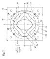
- the longitudinal annular blank 3 includes linear parts 3b, 3c on the left and right sides facing each other with a longitudinal hole 3a having a small width dimension w1 on the inner side, and a pair of curved parts 3d continuing both ends in the longitudinal direction of the linear parts 3b, 3c, as shown in Fig. 2 , and the longitudinal annular blank 3 is set in a first shaping device 4, as shown in Fig. 3 .
- the first shaping device 4 includes a moving plate 5 and a pair of front and back guide plates 6, where the moving plate 5 is guided by the guide plates 6 to move forward and backward in the left and right direction (direction of arrow X1, X2) by a forward/backward movement mechanism (not shown).
- the moving plate 5 includes a main body part 5a, and collar parts 5b, 5b formed on both ends in the front and back direction of the main body part 5a, where the collar parts 5b, 5b slidably go under the lower side of the edges 6a, 6a at the side facing the opponent in the guide plate 6, and a vertical step difference surface 5c formed at the boundary of the main body part 5a and the collar parts 5b, 5b is arranged so as to slidably contact the end surface 6b at the side facing the opponent in the guide plate 6.
- An inner die 8-1 having a boat shape in a projected plane is projected upward at the central part of the main body part 5a in the moving plate 5 on the line Y orthogonal to line X.
- the width dimension w2 of the inner die 8-1 is set to a size slightly smaller than the width dimension w1 of the longitudinal hole 3a so as to fit into the longitudinal hole 3a of the blank 3.
- a pair of front and back positioning projections 8-2, and two pairs of front and back positioning/deformation tolerating projections 9 are arranged on the guide plate 6 in the first shaping device 4.
- the pair of positioning projections 8-2 is provided to prevent the longitudinal annular blank 3 from moving in the direction of the arrow Y1, Y2 and to position the longitudinal annular blank 3 at an appropriate position when the longitudinal annular blank 3 is set in the first shaping device 4, and furthermore, is arranged at symmetrical positions with the line X in between so as to face each other on the line Y orthogonal to the line X, where the distance in between is set to a value slightly larger than the dimension in the longitudinal direction of the longitudinal annular blank 3 to enable the setting of the longitudinal annular blank 3.
- the two pairs of front and back positioning/deformation tolerating projections 9 are provided to prevent the longitudinal annular blank 3 from moving in the direction of the arrows X1, X2 and to position the longitudinal annular blank 3 at an appropriate position as well as to tolerate the deformation of the longitudinal annular blank 3 by an inner die 7 when the longitudinal annular blank 3 is set in the first shaping device 4, and is further arranged at symmetrical positions with the line X and the line Y passing through the center of the moving plate 5 in between, where the distance in between in the direction of the line X is set at a value slightly larger than the dimension in the width direction of the longitudinal annular blank 3 to enable the setting of the longitudinal annular blank 3.
- Each positioning/deformation tolerating projection 9 has a circular arc shaped deformation tolerating surface 9b formed in continuation to the positioning surface 9a that is parallel to the line Y.
- the moving plate 5 is moved in the direction of the arrow X2 in this state.
- the inner die 7 presses and energizes the linear part 3c on the right side of the longitudinal annular blank 3 in the direction of the arrow X2 from the inner side to bend in the direction of the arrow X2 as shown in Fig. 4 , and subsequently, the moving plate 5 is moved in the direction of the arrow X1 so that the inner die 7 presses and energizes the linear part 3b on the left side (see Fig. 3 ) of the longitudinal annular blank 3 in the direction of the arrow X1 from the inner side to bend in the direction of the arrow X1 as shown in Fig.
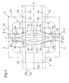
- the deformed longitudinal annular blank 3A shown in Fig. 4 is set in a second shaping device 11 shown in Fig. 5 .
- the second shaping device 11 includes a pair of left and right molding outer dies 12, and a pair of front and back regulating dies 13, where the molding outer die 12 is guided by a guide groove 14 and is moved forward and backward in the left and right direction (direction of arrows X1, X2) on the base 15 by a forward/backward movement mechanism (not shown).
- the molding outer die 12 includes a mounting surface 12a and a pressing surface 12b projecting vertically upward from the mounting surface 12a and having the projected plane depressed into a circular arc shape, where the curvature radius of the pressing surface 12b is set to a value larger than the curvature radius of the outer peripheral surface of the curved part 3d in the deformed longitudinal annular blank 3A.
- the regulating die 13 is formed at the end face on the side facing the opponent with a regulating surface 13a having the projected plane depressed into a circular arc shape.
- a holding inner die 16 projecting upward from the upper surface at the central part of the base 15 and having a boat shape in projected plane view is arranged extending in the direction of the line X, where the width dimension of the holding inner die 16 is set to a dimension slightly smaller than the width dimension of the longitudinal hole 3e so as to be fitted to the longitudinal hole 3e of the deformed longitudinal annular blank 3A.
- a circular arc shaped holding surface 16a is arranged vertically at both ends on the line X of the holding inner die 16, and a cut-out part 16b is formed on the lower side of the holding surface 16a and the vicinity thereof.
- the molding outer dies 12 are moved in the direction of the arrows X1, X2 in this state.
- the pressing surface 12b of the molding outer die 12 thereby presses and energizes the outer side of the curved part 3d of the deformed longitudinal annular blank 3A towards the curved part 3d on the opponent side.
- the mounting surface 12a of the molding outer die 12 enters the cut-out part 16b of the holding inner die 16. Therefore, as shown in Fig.
- both curved parts 3d are deformed along the pressing surface 12b when the radial outer surface of large curvature radius is pressed inward from the outer side by the pressing surface 12b depressed into a circular arc shape of the molding outer die 12 with the radial inner surface slightly pressed and widened by the circular arc shaped holding surface 16a of the holding inner die 16 and positioned with the movement in the directions of the arrows X1, X2 regulated, and thus "extension” is generated in the radial outer region having large curvature radius and "extension” in the radial inner region having small curvature radius in the curved part 3d are suppressed as much as possible, thinning of the radial inner region is avoided, and furthermore, flow of material that thickens the curved part 3d is generated so as to alleviate stress concentration at the radial inner region.
- both curved parts 3d can be molded to a large curved part 3D having a large curvature radius and being advantageous in manufacturing the ring-shaped member 1 without generating cracks at the curved part 3d, and thus the yield rate or the percentage of the ring-shaped member 1 with respect to the longitudinal annular blank 3A can be improved.
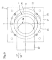
- the half-finished article 18 shown in Fig. 6 is further set in a third shaping device 19 shown in Fig. 7 in the next step.
- the third shaping device 19 includes a base 20, and an upper plate 21 for blocking the upper surface of the base 20 by way of a spacing in the height direction, where a guide groove 22 is formed in the base 20 on the line X passing through the center, and a moving plate 23 that freely moves forward and backward in the direction of the arrows X1, X2 is fitted into the guide groove 22.
- the moving plate 23 moves forward and backward in the direction of the arrows X1, X2 by a forward/backward moving mechanism (not shown).
- the upper surface of the moving plate 23 is in plane with the upper surface of the base 20, and a finishing inner die 24 having an elliptical shape in a projected plane view is arranged at the central part so as to project upward on a line Y passing through the center of the base 20 and being orthogonal to the line X.
- the finishing inner die 24 faces a window part 25 of a substantially perfect circle formed on the upper plate 21, and the inner peripheral surface of the window part 25 functions as an outer die.
- the moving plate 23 is moved in the direction of the arrow X2 in such state.
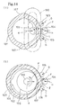
- the finishing inner die 24 presses and energizes the right half portion of the half-finished article 17 in the direction of the arrow X2 from the inner side and presses the outer peripheral surface of the right half portion against the inner peripheral surface of the right half portion in the window part 25 of a substantially perfect circle, as shown in Fig. 8 , thereby molding the right half portion of the half-finished article 18 into a semicircle. Subsequently, the moving plate 23 is moved in the direction of the arrow X1.
- the finishing inner die 24 thereby presses and energizes the left half portion of the half-finished article 18 in the direction of the arrow X1 from the inner side and presses the outer peripheral surface of the left half portion against the inner peripheral surface of the left half portion in the window part 25 of a substantially perfect circle as shown in Fig. 9 , thereby molding the left half portion of the half-finished article 18 into a semicircle to manufacture a ring-shaped member 1 shown in Fig. 9 and Fig. 12 .
- the ring-shaped member 1 shown in Fig. 9 and Fig. 12 is manufactured by punching out a plurality of longitudinal annular blanks 3 from a raw material 2 shown in Fig. 1 , and pressing and widening the longitudinal annular blanks 3 to be molded into an annular shape by first to third shaping devices 4, 11, 19, and thus the yield rate or the percentage of the weight of the ring-shaped member 1 with respect to the weight of the raw material 2 improves, and the cost of the ring-shaped member 1 can be reduced by removing the material such that the percentage of the skeleton S1 and the slug S2 of Fig. 1 with respect to the ring-shaped member 1 is suppressed lower than the percentage of the skeleton S1 and the slug S2 with respect to the ring-shaped member 1 described in Fig. 13 .
- each curved part 3d is deformed along the pressing surface 12b when the radial outer surface of large curvature radius is pressed inward from the outer side by the pressing surface 12b depressed into a circular arc shape of the molding outer die 12 with the radial inner surface slightly pressed and widened by the circular arc shaped holding surface 16a of the holding inner die 16 and positioned with the movement in the directions of the arrows X1, X2 regulated by pressing and energizing the outer side of the pair of curved parts 3d of the deformed longitudinal annular blank 3A towards the curved part 3d on the opponent side by the pressing surface 12b depressed to a circular arc shape of the molding outer die 12 by the second shaping device 11, and thus "extension" in the radial outer region having large curvature radius is suppressed as much as possible, thinning of the radial inner region is avoided, and furthermore, flow of material that thickens the curved part 3d is generated so as to alleviate stress concentration at the radial inner region
- both curved parts 3d can be molded to a large curved part 3D having a large curvature radius and being advantageous in manufacturing the ring-shaped member 1 without generating cracks at the curved part 3d, and thus the yield rate or the percentage of the ring-shaped member 1 with respect to the longitudinal annular blank 3A can be improved and the cost of the ring-shaped member 1 can be reduced.
- the longitudinal annular blank 3 having a small width dimension w1 of the longitudinal hole 3a is punched out, and such blank 3 is pressed and widened to manufacture the ring-shaped member 1, as shown in Fig. 2 , but, as shown in Fig. 10 , a longitudinal annular blank 27 of frame oval shape having a longitudinal hole 27a of oval shape in which the width dimension w3 is sufficiently larger than the width dimension w1 of Fig. 2 may be punched out, and such blank 27 may be pressed and widened through the same procedures as the above embodiment to be molded into the ring-shaped member 1.
- the yield rate or the percentage of the ring-shaped member 1 with respect to the longitudinal annular blank 27 of frame oval shape can be improved and the cost of the ring-shaped member 1 can be reduced, similar to the above embodiment.
- the outer end faces of the linear parts 3b, 3c in the longitudinal annular blank 3, 27 may be formed using both ends faces 2a in the width direction of the raw material 2, and the raw material 2 may be cut by the pressing device to form a pair of curved parts 3d continuing the pair of linear parts 3b, 3c to each other at both ends in the longitudinal direction. Therefore, the material can be removed such that the percentage of scraps with respect to the longitudinal annular blanks 3, 27 is suppressedto aminimum.
- the scraps are reduced to the slug S1 punched out and removed by punch in time of punching out the longitudinal hole 3a or the longitudinal hole 27a of oval shape, and an end plate part 2x of drum shape existing between the longitudinal annular blanks 3, 27 arrayed in the longitudinal direction and to be separated away from the raw material 2, as shown with slashes in Figs. 11(a) and 11(b) .
- the yield rate or the percentage of the weight of the ring-shaped member 1 with respect to the weight of the raw material 2 can be further improved.
Abstract
The outer side of a pair of curved parts 3d of a longitudinal annular blank is pressed and energized towards the curved part 3d of the opponent side with a molding outer die 14 of a shaping device 13 to press and widen each curved part 3d to a large curved part of large curvature radius, and a half-finished article 17 is molded, and thereafter, the half-finished article 17 is pressed and widened by cooperative operation of a finishing inner die of the shaping device and a window part of a perfect circle functioning as an outer die to manufacture a ring-shaped member. Therefore, a yield rate or a percentage of the weight of the ring-shaped member with respect to the weight of the raw material and the yield rate or the percentage of the ring-shaped member with respect to the blank can be improved, and the cost can be reduced.
Description
- The present invention relates to a method of manufacturing a ring-shaped member.
- A ring-
shaped member 1 as shown inFig. 12 has been conventionally manufactured through a method of punching out a plurality of annular ring-shaped members 1 by one column or a plurality of columns by a pressing device from araw material 2 having a predetermined plate thickness as shown inFigs. 13 (a) and 13 (b) . - However, in the conventional manufacturing method, the yield rate or the percentage of the weight of the ring-
shaped member 1 with respect to the weight of theraw material 2 is bad, and tends to increase the cost of the ring-shaped member 1. - This is because the material is removed at high percentage of skeleton S1 and slug S2 with respect to the ring-
shaped member 1. The "Skeleton" is a frame shaped scrap that remains after punching out a plurality of ring-shaped members 1, and the "slug" is a plurality of scraps punched out and removed with a punch when punching out the plurality of ring-shaped members 1. - A method of molding the ring-shaped member shown in Figs.
14(a) and 14(b) has thus been proposed (patent document 1). - The method of molding the ring-shaped member described in the
patent document 1 includes a step of continuously bending the width of an elliptical ring-shaped raw material into a circular shape while preventing the deformation thereof, and a step of making the raw material formed into a circular shape into a perfect circle. - That is, as shown in
Fig. 14 (a) , inner andouter rollers raw material 100, and a pair of freelymovable bending rollers 105 are arranged, where the inner andouter rollers bending rollers 105 in the direction of an arrow G while feeding the elliptical ring-shapedraw material 100 in the direction of an arrow L or in the opposite direction thereof, thereby sequentially performing the curvature process on the linear portion of theraw material 100 to be molded into araw material 101 of circular shape. - Thereafter, as shown in
Fig. 14 (b) , a large diameterinner roller 106 is externally fitted to theinner roller 103 so as to be simultaneously rotatable and inscribed to theraw material 101 formed into a circular shape, and the large diameterinner roller 106 and theouter rollers shaped member 102 molded to a perfect circle. -
- Patent document 1: Japanese Patent Application Laying-open No.
62-203633 - However, in the method of molding the ring-shaped member described in the
patent document 1, acurved part 107 having a small curvature radius remaining on the circularraw material 101 is pressed and widened from the inner side with a strong pressing force in the direction of an arrow K by the large diameterinner roller 106. When thecurved part 107 of small curvature radius is pressed and widened from the inner side, a large "extension" is generated at the radial inner region of small curvature radius in thecurved part 107 thereby thinning the relevant region and concentrating stress. Therefore, cracks may be generated at the radial inner region of thecurved part 107 in the process of molding the circular shapedraw material 101 into a perfect circular shaped ring-shaped member 102, which degrades the yield rate or the percentage of the perfect circular shaped ring-shaped member 102 with respect to the elliptical ring-shapedraw material 100, and increases the cost. - The present invention, in view of solving the above problems, aims to provide a method of manufacturing a ring-shaped member that improves the yield rate or the percentage of the weight of the ring-shaped member with respect to the weight of the raw material, and improves the yield rate or the percentage of the ring-shapedmember (correspond to ring-shaped part molded into a perfect circle described in the patent document 1) with respect to a longitudinal annular blank (correspond to elliptical ring-shaped raw material described in the patent document 1), even though the method can achieve a cost reduction.
- A method of manufacturing a ring-shaped member according to the present invention is provided, where a longitudinal annular blank is molded into an annular shape by pressing curved parts at both ends in the longitudinal direction towards the opponent side from the outer side.
The "Blank" is a plate punched out for manufacturing the ring-shaped member. - In this manner, the material is removed such that the percentage of the skeleton and the slug with respect to the ring-shaped member is suppressed low, and the yield rate or the percentage of the weight of the ring-shaped member with respect to the weight of the raw material can be improved. Furthermore, "extension" of the radial inner region having a small curvature radius at the curved parts is suppressed as small as possible by pressing the curved parts at both ends in the longitudinal direction towards the opponent side from the outer side, thinning of the radial inner region can be avoided, and furthermore, flow of material that thickens the curved part is generated and alleviates stress concentration at the radial inner region. As a result, cracks are not generated at the curved part, and the yield rate or the percentage of the ring-shaped member with respect to the longitudinal annular blank can be improved.
- The present invention desirably has the longitudinal annular blank molded to an annular shape by a shaping device including an inner die and an outer die. Accordingly, the high quality ring-shaped member can be efficiently manufactured, and cost can be reduced.
- The present invention desirably has the longitudinal annular blank which includes linear parts that face each other on both sides in the width direction with a longitudinal hole on the inner side and curved parts for continuing both ends in the longitudinal direction of the linear parts; and the dimension in the width direction of the longitudinal annular blank is widened by pressing and energizing the linear parts by the inner die fitted into the longitudinal hole, the outer side of the curved parts are pressed and energized towards the curved parts of the opponent side by a molding outer die with a holding inner die fitted into the longitudinal hole whose dimension in the width direction is widened, and the curved parts are pressed and widened to a large cured part having a large curvature radius.
- Therefore, if the outer side of the curved part is pressed and energized towards the curved part on the opponent side by the molding outer die with the holding inner die fitted into the longitudinal hole which dimension in the width direction has been widened after the dimension in the width direction of the longitudinal annular blank is widened by the inner die fitted into the longitudinal hole, such curved part is pressed inward from the outer side by the molding outer die while being positioned with the movement towards the curved part on the opponent side regulated by the holding inner die, whereby "extension" of the radial inner region having a small curvature radius at the curved parts is suppressed as small as possible, the thinning of the radial inner region is avoided, and furthermore, stress does not concentrate at the radial inner region and thus cracks are not generated at the curved part, and both curved parts are easily molded into a large curved part of large curvature radius.
- Furthermore, the present invention may have both end faces in the width direction of the longitudinal annular blank which are formed by both end faces in the width direction of the raw material, and the curved parts for continuing the linear parts to each other which are formed at both ends in the longitudinal direction by cutting the raw material. Accordingly, the material can be removed such that the percentage of scrap with respect to the longitudinal annular blank is suppressed to a minimum, and in consequence, the yield rate or the percentage of the weight of the ring-shaped member with respect to the weight of the raw material can be improved.
- According to the present invention, the ring-shaped member is manufactured by molding the longitudinal annular blank into an annular shape by pressing the curved parts at both ends in the longitudinal direction towards the opponent side from the outer side, and thus the yield rate or the percentage of the weight of the ring-shaped member with respect to the weight of the raw material improves and the cost of the ring-shaped member reduces by removing the material such that the percentage of the skeleton and the slug with respect to the ring-shaped member is suppressed low, and furthermore, "extension" of the radial inner region having a small curvature radius at the curved parts at both ends in the longitudinal direction is suppressed as small as possible, thinning of the radial inner region is avoided, and furthermore, flow of material that thickens the curved part is generated so that stress does not concentrate at the radial inner region. As a result, cracks are not generated at the curved part, and the yield rate or the percentage of the ring-shaped member with respect to the longitudinal annular blank can be improved.
-
-
Fig. 1 is a plan view showing a first embodiment of a step of punching out blanks from a raw material. -
Fig. 2 is an enlarged front view showing the blank punched out from the raw material ofFig. 1 . -
Fig. 3 is a plan view showing an embodiment in which the blank is set in a first shaping device. -
Fig. 4 is a plan view showing an embodiment of a state in which the deformed blank is molded by the first shaping device. -
Fig. 5 is a plan view showing an embodiment of a state in which the deformed blank is set in a second shaping device. -
Fig. 6 is a plan view showing an embodiment of a state in which a half-finished article is molded by the second shaping device. -
Fig. 7 is a plan view showing an embodiment of a state in which the half-finished article is set in a third shaping device. -
Fig. 8 is a plan view showing an embodiment of a state in which the right half portion of the half-finished article is molded into a semicircle by the third shaping device. -
Fig. 9 is a plan view showing an embodiment of a state in which the half-finished article is molded into a ring-shaped member by the third shaping device. -
Fig. 10 is an enlarged front view showing a second embodiment of a blank. -
Fig. 11 is a plan view showing another embodiment of a step of punching out the blank from the raw material. -
Fig.12 is a front view showing one example of the ring-shaped member. -
Fig. 13 is a plan view showing the conventional steps of punching out the blank from the material, where 13(a) shows punching out one column, 13 (b) shows punching out in parallel. -
Fig. 14 is an explanatory view of a method of molding the ring-shaped member described in thepatent document 1. -
- 1
- ring-shaped member
- 2
- raw material
- 2a
- end faces of raw material
- 3
- longitudinal annular blank
- 3a
- longitudinal hole
- 3b
- linear part on right side (linear part)
- 3c
- linear part on left side (linear part)
- 3D
- large curved part
- 3d
- curved part
- 4
- first shaping device (shaping device)
- 11
- second shaping device (shaping device)
- 12
- molding outer die (outer die)
- 16
- holding inner die (inner die)
- 19
- third shaping device (shaping device)
- 24
- finishing inner die (inner die)
- 25
- window part of perfect circle (outer die)
- A preferred embodiment of the method of manufacturing the ring-shaped member according to the present invention will now be described based on the drawings.
- As shown in
Fig. 1 , a plurality of longitudinalannular blanks 3 are punched out in series at apredetermined spacing 1 in the feeding direction by a pressing device while feeding theraw material 2 of a predetermined plate thickness in the longitudinal direction of theraw material 2 as shown with an arrow X. The longitudinal annular blank 3 includeslinear parts longitudinal hole 3a having a small width dimension w1 on the inner side, and a pair ofcurved parts 3d continuing both ends in the longitudinal direction of thelinear parts Fig. 2 , and the longitudinal annular blank 3 is set in afirst shaping device 4, as shown inFig. 3 . - The
first shaping device 4 includes a movingplate 5 and a pair of front andback guide plates 6, where the movingplate 5 is guided by theguide plates 6 to move forward and backward in the left and right direction (direction of arrow X1, X2) by a forward/backward movement mechanism (not shown). The movingplate 5 includes amain body part 5a, andcollar parts main body part 5a, where thecollar parts edges guide plate 6, and a verticalstep difference surface 5c formed at the boundary of themain body part 5a and thecollar parts end surface 6b at the side facing the opponent in theguide plate 6. An inner die 8-1 having a boat shape in a projected plane is projected upward at the central part of themain body part 5a in the movingplate 5 on the line Y orthogonal to line X. The width dimension w2 of the inner die 8-1 is set to a size slightly smaller than the width dimension w1 of thelongitudinal hole 3a so as to fit into thelongitudinal hole 3a of the blank 3. - A pair of front and back positioning projections 8-2, and two pairs of front and back positioning/
deformation tolerating projections 9 are arranged on theguide plate 6 in thefirst shaping device 4. As mentioned below, the pair of positioning projections 8-2 is provided to prevent the longitudinal annular blank 3 from moving in the direction of the arrow Y1, Y2 and to position the longitudinal annular blank 3 at an appropriate position when the longitudinal annular blank 3 is set in thefirst shaping device 4, and furthermore, is arranged at symmetrical positions with the line X in between so as to face each other on the line Y orthogonal to the line X, where the distance in between is set to a value slightly larger than the dimension in the longitudinal direction of the longitudinal annular blank 3 to enable the setting of the longitudinal annular blank 3. - As mentioned below, the two pairs of front and back positioning/
deformation tolerating projections 9 are provided to prevent the longitudinal annular blank 3 from moving in the direction of the arrows X1, X2 and to position the longitudinal annular blank 3 at an appropriate position as well as to tolerate the deformation of the longitudinal annular blank 3 by an inner die 7 when the longitudinal annular blank 3 is set in thefirst shaping device 4, and is further arranged at symmetrical positions with the line X and the line Y passing through the center of the movingplate 5 in between, where the distance in between in the direction of the line X is set at a value slightly larger than the dimension in the width direction of the longitudinal annular blank 3 to enable the setting of the longitudinal annular blank 3. Each positioning/deformation tolerating projection 9 has a circular arc shapeddeformation tolerating surface 9b formed in continuation to thepositioning surface 9a that is parallel to the line Y. - As shown in
Fig. 3 , when the longitudinal annular blank 3 is set in thefirst shaping device 4, anupper die 10 shown by a double-chain dashed line is lowered from above. The upper surfaces of theguide plate 6, the positioning projection 8-2, and the positioning/deformation tolerating projection 9 are thereby pressed by the lower surface of theupper die 10, and the upper surfaces of the blank 3 and the inner die 8-1 face the lower surface of theupper die 10 by way of an extremely small gap (small gap allowing slide movement) thereby preventing a warp of the blank 3. - The moving
plate 5 is moved in the direction of the arrow X2 in this state. The inner die 7 presses and energizes thelinear part 3c on the right side of the longitudinal annular blank 3 in the direction of the arrow X2 from the inner side to bend in the direction of the arrow X2 as shown inFig. 4 , and subsequently, the movingplate 5 is moved in the direction of the arrow X1 so that the inner die 7 presses and energizes thelinear part 3b on the left side (seeFig. 3 ) of the longitudinal annular blank 3 in the direction of the arrow X1 from the inner side to bend in the direction of the arrow X1 as shown inFig. 4 , where a longitudinal annular blank 3A in which the dimension in the width direction is widened and deformed from the dimension in the width direction ofFig. 3 is molded. In the process of molding, the widening deformation of thelinear parts Fig. 3 is tolerated since the outer surface in the width direction of the region near thecurved part 3d of thelinear parts deformation tolerating surface 9b of each of the two pairs of positioning/deformation tolerating projection 9, and the thinning of the widened and deformed part in time of widening deformation is suppressed since thedeformation tolerating surface 9b is formed into a circular arc shape. - In the next step, the deformed longitudinal annular blank 3A shown in
Fig. 4 is set in asecond shaping device 11 shown inFig. 5 . - The
second shaping device 11 includes a pair of left and right molding outer dies 12, and a pair of front and back regulating dies 13, where the molding outer die 12 is guided by aguide groove 14 and is moved forward and backward in the left and right direction (direction of arrows X1, X2) on thebase 15 by a forward/backward movement mechanism (not shown). - The molding outer die 12 includes a mounting
surface 12a and apressing surface 12b projecting vertically upward from the mountingsurface 12a and having the projected plane depressed into a circular arc shape, where the curvature radius of thepressing surface 12b is set to a value larger than the curvature radius of the outer peripheral surface of thecurved part 3d in the deformed longitudinal annular blank 3A. The regulating die 13 is formed at the end face on the side facing the opponent with a regulatingsurface 13a having the projected plane depressed into a circular arc shape. Furthermore, a holdinginner die 16 projecting upward from the upper surface at the central part of thebase 15 and having a boat shape in projected plane view is arranged extending in the direction of the line X, where the width dimension of the holdinginner die 16 is set to a dimension slightly smaller than the width dimension of thelongitudinal hole 3e so as to be fitted to thelongitudinal hole 3e of the deformed longitudinal annular blank 3A. A circular arc shaped holdingsurface 16a is arranged vertically at both ends on the line X of the holdinginner die 16, and a cut-outpart 16b is formed on the lower side of the holdingsurface 16a and the vicinity thereof. - As shown in
Fig. 5 , after the longitudinal annular blank 3A is set in thesecond shaping device 11 with the holdinginner die 16 sandwiched by thelinear parts curved part 3d and the vicinity of the blank 3A mounted on the mountingsurface 12a of the molding outer die 12, anupper die 17 shown by a double chain-dashed line is lowered from above. The upper surfaces of the regulating die 13 and the holdinginner die 16 are pressed by the lower surface of theupper die 17, and the upper surfaces of the longitudinal annular blank 3A and the molding outer die 12 face the lower surface of theupper die 17 by way of an extremely small gap (small gap allowing slide movement) thereby preventing the warp of the blank 3A. - The molding outer dies 12 are moved in the direction of the arrows X1, X2 in this state. The
pressing surface 12b of the molding outer die 12 thereby presses and energizes the outer side of thecurved part 3d of the deformed longitudinal annular blank 3A towards thecurved part 3d on the opponent side. In this case, the mountingsurface 12a of the molding outer die 12 enters the cut-outpart 16b of the holdinginner die 16. Therefore, as shown inFig. 6 , bothcurved parts 3d are deformed along thepressing surface 12b when the radial outer surface of large curvature radius is pressed inward from the outer side by thepressing surface 12b depressed into a circular arc shape of the molding outer die 12 with the radial inner surface slightly pressed and widened by the circular arc shaped holdingsurface 16a of the holdinginner die 16 and positioned with the movement in the directions of the arrows X1, X2 regulated, and thus "extension" is generated in the radial outer region having large curvature radius and "extension" in the radial inner region having small curvature radius in thecurved part 3d are suppressed as much as possible, thinning of the radial inner region is avoided, and furthermore, flow of material that thickens thecurved part 3d is generated so as to alleviate stress concentration at the radial inner region. As a result, bothcurved parts 3d can be molded to a largecurved part 3D having a large curvature radius and being advantageous in manufacturing the ring-shapedmember 1 without generating cracks at thecurved part 3d, and thus the yield rate or the percentage of the ring-shapedmember 1 with respect to the longitudinal annular blank 3A can be improved. - In the process of molding both
curved parts 3d to the largecurved part 3D having a large curvature radius, thelinear parts Fig. 5 are widened in the direction of the arrows Y1, Y2 thereby forming a curved bulge-out-part 3E at the central part, as shown inFig. 6 , where the deformed longitudinal annular blank 3A (seeFig. 5 ) is regulated from widening in excess in the direction of the arrows Y1, Y2 when the outer surface of the bulge-outpart 3E contacts the regulatingsurface 13a depressed into a circular arc shape of the regulating die 13, and a half-finished article 18 including a pair of largecurved parts 3D of large curvature radius and a pair of curved bulge-outparts 3E, and having the largecurved parts 3D and the bulge-outparts 3E continuously connected to each other by way of four shortlinear parts 3F is molded. - The half-
finished article 18 shown inFig. 6 is further set in athird shaping device 19 shown inFig. 7 in the next step. - The
third shaping device 19 includes abase 20, and anupper plate 21 for blocking the upper surface of the base 20 by way of a spacing in the height direction, where aguide groove 22 is formed in thebase 20 on the line X passing through the center, and a movingplate 23 that freely moves forward and backward in the direction of the arrows X1, X2 is fitted into theguide groove 22. The movingplate 23 moves forward and backward in the direction of the arrows X1, X2 by a forward/backward moving mechanism (not shown). The upper surface of the movingplate 23 is in plane with the upper surface of thebase 20, and a finishinginner die 24 having an elliptical shape in a projected plane view is arranged at the central part so as to project upward on a line Y passing through the center of thebase 20 and being orthogonal to the line X. The finishinginner die 24 faces awindow part 25 of a substantially perfect circle formed on theupper plate 21, and the inner peripheral surface of thewindow part 25 functions as an outer die. - As shown in
Fig. 7 , when the half-finished article 17 is set in thethird shaping device 19, anupper die 26 shown with a double chain-dashed line is lowered from above. The upper surface of theupper plate 21 is thereby pressed by the lower surface of theupper die 26, and the upper surfaces of the half-finished article 17 and the finishinginner die 24 face the lower surface of theupper die 26 by way of an extremely small gap (small gap allowing slide movement) thereby preventing the warp of the half-finished article 17. - The moving
plate 23 is moved in the direction of the arrow X2 in such state. The finishinginner die 24 presses and energizes the right half portion of the half-finished article 17 in the direction of the arrow X2 from the inner side and presses the outer peripheral surface of the right half portion against the inner peripheral surface of the right half portion in thewindow part 25 of a substantially perfect circle, as shown inFig. 8 , thereby molding the right half portion of the half-finished article 18 into a semicircle. Subsequently, the movingplate 23 is moved in the direction of the arrow X1. The finishinginner die 24 thereby presses and energizes the left half portion of the half-finished article 18 in the direction of the arrow X1 from the inner side and presses the outer peripheral surface of the left half portion against the inner peripheral surface of the left half portion in thewindow part 25 of a substantially perfect circle as shown inFig. 9 , thereby molding the left half portion of the half-finished article 18 into a semicircle to manufacture a ring-shapedmember 1 shown inFig. 9 andFig. 12 . - Therefore, according to the present invention, the ring-shaped
member 1 shown inFig. 9 andFig. 12 is manufactured by punching out a plurality of longitudinalannular blanks 3 from araw material 2 shown inFig. 1 , and pressing and widening the longitudinalannular blanks 3 to be molded into an annular shape by first tothird shaping devices member 1 with respect to the weight of theraw material 2 improves, and the cost of the ring-shapedmember 1 can be reduced by removing the material such that the percentage of the skeleton S1 and the slug S2 ofFig. 1 with respect to the ring-shapedmember 1 is suppressed lower than the percentage of the skeleton S1 and the slug S2 with respect to the ring-shapedmember 1 described inFig. 13 . - Furthermore, each
curved part 3d is deformed along thepressing surface 12b when the radial outer surface of large curvature radius is pressed inward from the outer side by thepressing surface 12b depressed into a circular arc shape of the molding outer die 12 with the radial inner surface slightly pressed and widened by the circular arc shaped holdingsurface 16a of the holdinginner die 16 and positioned with the movement in the directions of the arrows X1, X2 regulated by pressing and energizing the outer side of the pair ofcurved parts 3d of the deformed longitudinal annular blank 3A towards thecurved part 3d on the opponent side by thepressing surface 12b depressed to a circular arc shape of the molding outer die 12 by thesecond shaping device 11, and thus "extension" in the radial outer region having large curvature radius is suppressed as much as possible, thinning of the radial inner region is avoided, and furthermore, flow of material that thickens thecurved part 3d is generated so as to alleviate stress concentration at the radial inner region. As a result, bothcurved parts 3d can be molded to a largecurved part 3D having a large curvature radius and being advantageous in manufacturing the ring-shapedmember 1 without generating cracks at thecurved part 3d, and thus the yield rate or the percentage of the ring-shapedmember 1 with respect to the longitudinal annular blank 3A can be improved and the cost of the ring-shapedmember 1 can be reduced. - In the above embodiment, the longitudinal annular blank 3 having a small width dimension w1 of the
longitudinal hole 3a is punched out, and such blank 3 is pressed and widened to manufacture the ring-shapedmember 1, as shown inFig. 2 , but, as shown inFig. 10 , a longitudinal annular blank 27 of frame oval shape having alongitudinal hole 27a of oval shape in which the width dimension w3 is sufficiently larger than the width dimension w1 ofFig. 2 may be punched out, and such blank 27 may be pressed and widened through the same procedures as the above embodiment to be molded into the ring-shapedmember 1. In this case as well, the yield rate or the percentage of the ring-shapedmember 1 with respect to the longitudinal annular blank 27 of frame oval shape can be improved and the cost of the ring-shapedmember 1 can be reduced, similar to the above embodiment. - Moreover, as shown in
Figs. 11(a) and 11(b) , the outer end faces of thelinear parts raw material 2, and theraw material 2 may be cut by the pressing device to form a pair ofcurved parts 3d continuing the pair oflinear parts annular blanks longitudinal hole 3a or thelongitudinal hole 27a of oval shape, and anend plate part 2x of drum shape existing between the longitudinalannular blanks raw material 2, as shown with slashes inFigs. 11(a) and 11(b) . As a result, the yield rate or the percentage of the weight of the ring-shapedmember 1 with respect to the weight of theraw material 2 can be further improved.
Claims (4)
- A method of manufacturing a ring-shaped member, wherein a longitudinal annular blank is molded into an annular shape by pressing curved parts at both ends in the longitudinal direction towards the opponent side from the outer side.
- The method of manufacturing the ring-shaped member according to claim 1, wherein the longitudinal annular blank is molded into an annular shape by a shaping device including an inner die and an outer die.
- The method of manufacturing the ring-shaped member according to claim 1 or 2, wherein
the longitudinal annular blank includes linear parts that face each other on both sides in the width direction with a longitudinal hole on the inner side and curved parts for continuing both ends in the longitudinal direction of the linear parts; and
the dimension in the width direction of the longitudinal annular blank is widened by pressing and energizing the linear parts by the inner die fitted into the longitudinal hole, the outer side of the curved parts are pressed and energized towards the curved parts of the opponent side by a molding outer die with a holding inner die fitted into a longitudinal hole which dimension in the width direction is widened, and the curved parts are pressed and widened to a large cured part having a large curvature radius. - The method of manufacturing the ring-shaped member according to any one of claims 1, 2 or 3, wherein both end faces in the width direction of the longitudinal annular blank are formed by both end faces in the width direction of the rawmaterial, and the curved parts for continuing the linear parts to each other are formed at both ends in the longitudinal direction by cutting the raw material.
Applications Claiming Priority (1)
| Application Number | Priority Date | Filing Date | Title |
|---|---|---|---|
| PCT/JP2005/018840 WO2007043176A1 (en) | 2005-10-13 | 2005-10-13 | Method of manufacturing ring-shaped member |
Publications (1)
| Publication Number | Publication Date |
|---|---|
| EP1946862A1 true EP1946862A1 (en) | 2008-07-23 |
Family
ID=37942445
Family Applications (3)
| Application Number | Title | Priority Date | Filing Date |
|---|---|---|---|
| EP05793177A Withdrawn EP1946862A1 (en) | 2005-10-13 | 2005-10-13 | Method of manufacturing ring-shaped member |
| EP06811592A Withdrawn EP1949984A1 (en) | 2005-10-13 | 2006-10-11 | Method of manufacturing ring-shaped member |
| EP06811594A Withdrawn EP1949985A1 (en) | 2005-10-13 | 2006-10-11 | Method for manufacturing ring-shaped member |
Family Applications After (2)
| Application Number | Title | Priority Date | Filing Date |
|---|---|---|---|
| EP06811592A Withdrawn EP1949984A1 (en) | 2005-10-13 | 2006-10-11 | Method of manufacturing ring-shaped member |
| EP06811594A Withdrawn EP1949985A1 (en) | 2005-10-13 | 2006-10-11 | Method for manufacturing ring-shaped member |
Country Status (6)
| Country | Link |
|---|---|
| US (3) | US7849724B2 (en) |
| EP (3) | EP1946862A1 (en) |
| JP (1) | JP4496215B2 (en) |
| KR (2) | KR100990308B1 (en) |
| CN (3) | CN100553820C (en) |
| WO (3) | WO2007043176A1 (en) |
Cited By (1)
| Publication number | Priority date | Publication date | Assignee | Title |
|---|---|---|---|---|
| CN110184836A (en) * | 2019-05-31 | 2019-08-30 | 燕山大学 | A kind of automatic hook device of wirerope steel wire |
Families Citing this family (7)
| Publication number | Priority date | Publication date | Assignee | Title |
|---|---|---|---|---|
| US20090301162A1 (en) * | 2008-06-06 | 2009-12-10 | Yahya Hodjat | Method of making a ring |
| CN101791656A (en) * | 2010-03-11 | 2010-08-04 | 杭州兴意金属制造有限公司 | Stamping and discharging method for brake shoe rib plate |
| CN102513780A (en) * | 2011-12-22 | 2012-06-27 | 西南铝业(集团)有限责任公司 | Forging process of large forged ring |
| RU2645419C1 (en) * | 2016-12-06 | 2018-02-21 | Александр Иванович Максимов | Device for aligning curved wall of tube from aluminum foil for packaging |
| RU2646176C1 (en) * | 2016-12-12 | 2018-03-01 | Александр Иванович Максимов | Method for slabbing curvilinear wall of tube from aluminum foil for packaging |
| CN113829063B (en) * | 2021-09-23 | 2024-02-20 | 周六福珠宝股份有限公司 | Diamond ring cutting device |
| CN114700435B (en) * | 2022-02-24 | 2024-03-15 | 永康市中景金属制品有限公司 | Metal ring stamping equipment and ring piece manufacturing method |
Family Cites Families (12)
| Publication number | Priority date | Publication date | Assignee | Title |
|---|---|---|---|---|
| US1091751A (en) * | 1913-03-12 | 1914-03-31 | Pittsburgh Steel Products Co | Method of forming axle-housings. |
| US1839530A (en) * | 1929-03-07 | 1932-01-05 | Victor F Braun | Method and apparatus for forming rings |
| US2670025A (en) * | 1951-03-14 | 1954-02-23 | Moore Drop Forging Company | Apparatus for spreading split bars to circular forms |
| FR2462215A1 (en) * | 1979-07-26 | 1981-02-13 | Ferodo Sa | METHOD FOR CONFORMING A TUBE ESPECIALLY FOR HEAT EXCHANGER AND HEAT EXCHANGER WITH TUBES SO COMPLIANT |
| JPS58128231A (en) | 1982-01-28 | 1983-07-30 | Honda Motor Co Ltd | Blanking method of blank material for automobile body |
| JPH0647139B2 (en) | 1986-03-01 | 1994-06-22 | 株式会社日立製作所 | Ring flange molding method and molding apparatus |
| JPS6442721U (en) * | 1987-09-10 | 1989-03-14 | ||
| IT1261103B (en) * | 1993-10-29 | 1996-05-09 | Borletti Climatizzazione | PROCEDURE FOR CONFORMING ACCORDING TO A CIRCULAR CROSS SECTION THE END OF AN OBLONG CROSS SECTION TUBE. |
| DE60044487D1 (en) * | 1999-10-22 | 2010-07-15 | Honda Motor Co Ltd | Process for producing a laminated ring |
| SE0100143L (en) * | 2001-01-17 | 2002-07-18 | Lindab Ab | Coupling ring and device and method for using it |
| JP4698890B2 (en) * | 2001-03-28 | 2011-06-08 | 坂本工業株式会社 | Processing method of protruding part of deformed pipe |
| US6655182B2 (en) * | 2001-05-18 | 2003-12-02 | Lindab Ab | Apparatus and method for reshaping tubes |
-
2005
- 2005-10-13 WO PCT/JP2005/018840 patent/WO2007043176A1/en active Application Filing
- 2005-10-13 US US12/083,237 patent/US7849724B2/en not_active Expired - Fee Related
- 2005-10-13 EP EP05793177A patent/EP1946862A1/en not_active Withdrawn
- 2005-10-13 JP JP2006522833A patent/JP4496215B2/en not_active Expired - Fee Related
- 2005-10-13 CN CNB2005800517977A patent/CN100553820C/en not_active Expired - Fee Related
-
2006
- 2006-10-11 EP EP06811592A patent/EP1949984A1/en not_active Withdrawn
- 2006-10-11 CN CN2006800374855A patent/CN101282801B/en not_active Expired - Fee Related
- 2006-10-11 WO PCT/JP2006/320287 patent/WO2007043565A1/en active Application Filing
- 2006-10-11 CN CN2006800374164A patent/CN101282800B/en not_active Expired - Fee Related
- 2006-10-11 KR KR1020087007294A patent/KR100990308B1/en not_active IP Right Cessation
- 2006-10-11 KR KR1020087007293A patent/KR20080039518A/en not_active Application Discontinuation
- 2006-10-11 US US12/083,232 patent/US20090158808A1/en not_active Abandoned
- 2006-10-11 EP EP06811594A patent/EP1949985A1/en not_active Withdrawn
- 2006-10-11 WO PCT/JP2006/320285 patent/WO2007043564A1/en active Application Filing
- 2006-10-11 US US12/083,231 patent/US20090158803A1/en not_active Abandoned
Non-Patent Citations (1)
| Title |
|---|
| See references of WO2007043176A1 * |
Cited By (1)
| Publication number | Priority date | Publication date | Assignee | Title |
|---|---|---|---|---|
| CN110184836A (en) * | 2019-05-31 | 2019-08-30 | 燕山大学 | A kind of automatic hook device of wirerope steel wire |
Also Published As
| Publication number | Publication date |
|---|---|
| US7849724B2 (en) | 2010-12-14 |
| EP1949985A1 (en) | 2008-07-30 |
| WO2007043565A1 (en) | 2007-04-19 |
| JPWO2007043176A1 (en) | 2009-04-16 |
| CN101282800B (en) | 2010-08-11 |
| CN101282799A (en) | 2008-10-08 |
| CN100553820C (en) | 2009-10-28 |
| KR100990308B1 (en) | 2010-10-26 |
| CN101282800A (en) | 2008-10-08 |
| WO2007043564A1 (en) | 2007-04-19 |
| US20090255318A1 (en) | 2009-10-15 |
| KR20080039518A (en) | 2008-05-07 |
| WO2007043176A1 (en) | 2007-04-19 |
| US20090158808A1 (en) | 2009-06-25 |
| CN101282801B (en) | 2010-05-19 |
| JP4496215B2 (en) | 2010-07-07 |
| CN101282801A (en) | 2008-10-08 |
| KR20080039519A (en) | 2008-05-07 |
| EP1949984A1 (en) | 2008-07-30 |
| US20090158803A1 (en) | 2009-06-25 |
Similar Documents
| Publication | Publication Date | Title |
|---|---|---|
| EP1946862A1 (en) | Method of manufacturing ring-shaped member | |
| EP1128088B1 (en) | Method and apparatus for blanking elements of belt for continuously variable transmission | |
| EP1733818B1 (en) | Shearing device | |
| US20100083727A1 (en) | Process for manufacturing ring-shaped member | |
| CN211437767U (en) | Punching and trimming forming die for two ends of inner reinforcing plate of automobile front wheel | |
| JP4390374B2 (en) | Compound press machine | |
| CN210816988U (en) | Progressive blanking die | |
| JP2006043719A (en) | Element for continuously variable transmission and method for manufacturing the same | |
| JP5556685B2 (en) | Punching device | |
| JP4734211B2 (en) | Method for manufacturing ring-shaped member | |
| JP2000317544A (en) | Method and device for press working | |
| JP2007326105A (en) | Press forming die and press forming method | |
| JP2007105797A (en) | Method for manufacturing ring shape member | |
| KR102369612B1 (en) | Precision processing washer with side cutting step and its continuous manufacturing method and device | |
| JP4867502B2 (en) | Press machine | |
| JP2023127802A (en) | Metal press progressive die with square-cut cutting step | |
| CN111989213A (en) | Apparatus for manufacturing press-worked product | |
| KR20080039517A (en) | Method of manufacturing ring-shaped member | |
| JP2003220434A (en) | Manufacturing method for partial tubular parts with flange | |
| JP2000202526A (en) | Bending device | |
| JPS6024228A (en) | Beading method of cylindrical member | |
| JPH04258324A (en) | Press die | |
| JP2009101403A (en) | Blanking method | |
| JPH03189029A (en) | Method and apparatus for joining sheet |
Legal Events
| Date | Code | Title | Description |
|---|---|---|---|
| PUAI | Public reference made under article 153(3) epc to a published international application that has entered the european phase |
Free format text: ORIGINAL CODE: 0009012 |
|
| 17P | Request for examination filed |
Effective date: 20080513 |
|
| AK | Designated contracting states |
Kind code of ref document: A1 Designated state(s): AT BE BG CH CY CZ DE DK EE ES FI FR GB GR HU IE IS IT LI LT LU LV MC NL PL PT RO SE SI SK TR |
|
| STAA | Information on the status of an ep patent application or granted ep patent |
Free format text: STATUS: THE APPLICATION IS DEEMED TO BE WITHDRAWN |
|
| 18D | Application deemed to be withdrawn |
Effective date: 20110503 |