EP1583166A2 - Organische Leuchtdiode mit auf ZrO2 imobilisierten Ir-Komplexen - Google Patents
Organische Leuchtdiode mit auf ZrO2 imobilisierten Ir-Komplexen Download PDFInfo
- Publication number
- EP1583166A2 EP1583166A2 EP05006873A EP05006873A EP1583166A2 EP 1583166 A2 EP1583166 A2 EP 1583166A2 EP 05006873 A EP05006873 A EP 05006873A EP 05006873 A EP05006873 A EP 05006873A EP 1583166 A2 EP1583166 A2 EP 1583166A2
- Authority
- EP
- European Patent Office
- Prior art keywords
- organic
- organic electroluminescence
- electroluminescence device
- layer
- cathode
- Prior art date
- Legal status (The legal status is an assumption and is not a legal conclusion. Google has not performed a legal analysis and makes no representation as to the accuracy of the status listed.)
- Withdrawn
Links
Images


Classifications
-
- H—ELECTRICITY
- H05—ELECTRIC TECHNIQUES NOT OTHERWISE PROVIDED FOR
- H05B—ELECTRIC HEATING; ELECTRIC LIGHT SOURCES NOT OTHERWISE PROVIDED FOR; CIRCUIT ARRANGEMENTS FOR ELECTRIC LIGHT SOURCES, IN GENERAL
- H05B33/00—Electroluminescent light sources
- H05B33/12—Light sources with substantially two-dimensional [2D] radiating surfaces
- H05B33/14—Light sources with substantially two-dimensional [2D] radiating surfaces characterised by the chemical or physical composition or the arrangement of the electroluminescent material, or by the simultaneous addition of the electroluminescent material in or onto the light source
-
- C—CHEMISTRY; METALLURGY
- C09—DYES; PAINTS; POLISHES; NATURAL RESINS; ADHESIVES; COMPOSITIONS NOT OTHERWISE PROVIDED FOR; APPLICATIONS OF MATERIALS NOT OTHERWISE PROVIDED FOR
- C09K—MATERIALS FOR MISCELLANEOUS APPLICATIONS, NOT PROVIDED FOR ELSEWHERE
- C09K11/00—Luminescent materials, e.g. electroluminescent or chemiluminescent
- C09K11/06—Luminescent materials, e.g. electroluminescent or chemiluminescent containing organic luminescent materials
-
- H—ELECTRICITY
- H10—SEMICONDUCTOR DEVICES; ELECTRIC SOLID-STATE DEVICES NOT OTHERWISE PROVIDED FOR
- H10K—ORGANIC ELECTRIC SOLID-STATE DEVICES
- H10K85/00—Organic materials used in the body or electrodes of devices covered by this subclass
- H10K85/30—Coordination compounds
- H10K85/341—Transition metal complexes, e.g. Ru(II)polypyridine complexes
- H10K85/342—Transition metal complexes, e.g. Ru(II)polypyridine complexes comprising iridium
-
- C—CHEMISTRY; METALLURGY
- C09—DYES; PAINTS; POLISHES; NATURAL RESINS; ADHESIVES; COMPOSITIONS NOT OTHERWISE PROVIDED FOR; APPLICATIONS OF MATERIALS NOT OTHERWISE PROVIDED FOR
- C09K—MATERIALS FOR MISCELLANEOUS APPLICATIONS, NOT PROVIDED FOR ELSEWHERE
- C09K2211/00—Chemical nature of organic luminescent or tenebrescent compounds
- C09K2211/10—Non-macromolecular compounds
- C09K2211/1018—Heterocyclic compounds
- C09K2211/1025—Heterocyclic compounds characterised by ligands
- C09K2211/1029—Heterocyclic compounds characterised by ligands containing one nitrogen atom as the heteroatom
-
- C—CHEMISTRY; METALLURGY
- C09—DYES; PAINTS; POLISHES; NATURAL RESINS; ADHESIVES; COMPOSITIONS NOT OTHERWISE PROVIDED FOR; APPLICATIONS OF MATERIALS NOT OTHERWISE PROVIDED FOR
- C09K—MATERIALS FOR MISCELLANEOUS APPLICATIONS, NOT PROVIDED FOR ELSEWHERE
- C09K2211/00—Chemical nature of organic luminescent or tenebrescent compounds
- C09K2211/18—Metal complexes
- C09K2211/185—Metal complexes of the platinum group, i.e. Os, Ir, Pt, Ru, Rh or Pd
-
- H—ELECTRICITY
- H10—SEMICONDUCTOR DEVICES; ELECTRIC SOLID-STATE DEVICES NOT OTHERWISE PROVIDED FOR
- H10K—ORGANIC ELECTRIC SOLID-STATE DEVICES
- H10K30/00—Organic devices sensitive to infrared radiation, light, electromagnetic radiation of shorter wavelength or corpuscular radiation
- H10K30/10—Organic devices sensitive to infrared radiation, light, electromagnetic radiation of shorter wavelength or corpuscular radiation comprising heterojunctions between organic semiconductors and inorganic semiconductors
- H10K30/15—Sensitised wide-bandgap semiconductor devices, e.g. dye-sensitised TiO2
-
- H—ELECTRICITY
- H10—SEMICONDUCTOR DEVICES; ELECTRIC SOLID-STATE DEVICES NOT OTHERWISE PROVIDED FOR
- H10K—ORGANIC ELECTRIC SOLID-STATE DEVICES
- H10K50/00—Organic light-emitting devices
- H10K50/10—OLEDs or polymer light-emitting diodes [PLED]
- H10K50/11—OLEDs or polymer light-emitting diodes [PLED] characterised by the electroluminescent [EL] layers
-
- H—ELECTRICITY
- H10—SEMICONDUCTOR DEVICES; ELECTRIC SOLID-STATE DEVICES NOT OTHERWISE PROVIDED FOR
- H10K—ORGANIC ELECTRIC SOLID-STATE DEVICES
- H10K59/00—Integrated devices, or assemblies of multiple devices, comprising at least one organic light-emitting element covered by group H10K50/00
- H10K59/10—OLED displays
- H10K59/12—Active-matrix OLED [AMOLED] displays
- H10K59/122—Pixel-defining structures or layers, e.g. banks
-
- H—ELECTRICITY
- H10—SEMICONDUCTOR DEVICES; ELECTRIC SOLID-STATE DEVICES NOT OTHERWISE PROVIDED FOR
- H10K—ORGANIC ELECTRIC SOLID-STATE DEVICES
- H10K71/00—Manufacture or treatment specially adapted for the organic devices covered by this subclass
- H10K71/10—Deposition of organic active material
-
- H—ELECTRICITY
- H10—SEMICONDUCTOR DEVICES; ELECTRIC SOLID-STATE DEVICES NOT OTHERWISE PROVIDED FOR
- H10K—ORGANIC ELECTRIC SOLID-STATE DEVICES
- H10K85/00—Organic materials used in the body or electrodes of devices covered by this subclass
- H10K85/10—Organic polymers or oligomers
- H10K85/111—Organic polymers or oligomers comprising aromatic, heteroaromatic, or aryl chains, e.g. polyaniline, polyphenylene or polyphenylene vinylene
- H10K85/113—Heteroaromatic compounds comprising sulfur or selene, e.g. polythiophene
- H10K85/1135—Polyethylene dioxythiophene [PEDOT]; Derivatives thereof
-
- H—ELECTRICITY
- H10—SEMICONDUCTOR DEVICES; ELECTRIC SOLID-STATE DEVICES NOT OTHERWISE PROVIDED FOR
- H10K—ORGANIC ELECTRIC SOLID-STATE DEVICES
- H10K85/00—Organic materials used in the body or electrodes of devices covered by this subclass
- H10K85/10—Organic polymers or oligomers
- H10K85/141—Organic polymers or oligomers comprising aliphatic or olefinic chains, e.g. poly N-vinylcarbazol, PVC or PTFE
- H10K85/146—Organic polymers or oligomers comprising aliphatic or olefinic chains, e.g. poly N-vinylcarbazol, PVC or PTFE poly N-vinylcarbazol; Derivatives thereof
Definitions
- the present invention relates to an organic electroluminescence device manufactured by using a liquid-phase process, a manufacturing method thereof and electronic equipment.
- An organic electroluminescence (EL) element which is a constituent member of the organic electroluminescence device, generally has an organic light-emitting layer made of an organic light-emitting material between an anode and a cathode. Electrons and electron holes which are injected through the anode and the cathode are recombined in the light-emitting layer and an excited energy is emitted as light.
- Such organic EL device usually has an electron hole injection layer (also called as “electron hole transport layer”) that becomes an anode buffer and an electron injection layer (also called as “electron transport layer”) that becomes a cathode buffer because a charge injection barrier among the electrodes and the light-emitting layer is high. They are provided in layers in the organic EL device.
- An electron injection material (also called as “electron transport material”) has a high reactivity with oxygen and the like in principal, in other words, it has a high probability of undergoing chemical change under normal conditions. Therefore, it is difficult to maintain a reliability of the electron injection material for a prolonged period. For this reason, a part including the cathode which injects and transfers electrons becomes one of deterioration factors. Meanwhile, demands for the organic electroluminescence have been increasing every day and especially the reliability is becoming a major issue. A conventional electron injection transfer layer made of previously-existing organic materials is not sufficient and a radical improvement is needed.
- the present invention has been developed in consideration of the above-mentioned problems, and intended to provide an organic electroluminescence device which is reliable and/or has a long operation life.
- the present invention also intends to provide electronic equipment having an organic electroluminescence device according the present invention.
- An organic electroluminescence device of the present invention has a light-emitting functional organic material part provided between an electrode formed on a base body and an electrode that opposes the electrode.
- the functional organic material layer contains at least a particle of a metallic compound, a metal complex and an organic material.
- the organic electroluminescence device conducts an electron injection and propagation, which is a key factor for deterioration, through not only the organic material but also together with an inorganic material.
- a hole injection layer, a hole transport layer and an electron injection layer may exist in a form of at least a layer or layers.
- a liquid-phase process is used.
- the liquid-phase process includes a spin-coat method, a dip method and a droplet discharging method.
- the electronic equipment according to the present invention includes the above-described organic electroluminescence device of the present invention.
- FIG. 1 is a plan view schematically showing an organic electroluminescence device 1.
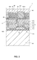
- FIG. 2 is a sectional view of the organic electroluminescence device along the line A-A shown in FIG. 1 schematically showing a sectional structure.
- the organic electroluminescence device 1 has a dot that emits a green (G) light in a real display region 4 as shown in FIG. 1 and this enables the organic electroluminescence device to display in one color.
- G green
- the organic electroluminescence device 1 of this embodiment is a bottom-emission type. This means that the light is taken out from a substrate 20 side. Therefore, a transparent or translucent substrate made of such as glass, quartz and resin (plastic or a plastic film) is used as the substrate 20.
- the organic electroluminescence device When the organic electroluminescence device is a so-called top-emission type, the light is taken out from a sealing substrate (not shown in the figures) side which is opposed to the substrate 20. Therefore, either the transparent substrate or an opaque substrate can be used as the substrate 20.
- the opaque substrate for example, ceramics such as alumina, a metal sheet treated with insulating such as a stainless steel treated with surface oxidation, heat-hardening resin and thermoplastic resin can be used.
- an electroluminescence element is provided on a base body 100.
- the base body 100 includes the substrate 20 and a circuit member 11 formed on the substrate 20.
- the circuit member 11 includes a protection layer 12 formed on the substrate 20 and made of, for example, an oxide silicon layer, a driving thin film transistor (TFT) 123 formed on the protection layer, a first interlayer insulation layer 15 and a second interlayer insulation layer 18.
- the driving TFT 123 includes a semiconductor layer 13 made of silicon, a gate insulating layer 14 formed on the semiconductor layer 13, a gate electrode 19 formed on the gate insulating layer 14, a source electrode 16 and a drain electrode 17.
- the organic electroluminescence element is provided on the circuit member 11.
- the organic electroluminescence element includes a picture electrode 23 which serves as an anode, a hole injection layer 70 which injects or transports electron holes from the picture electrode 23 and is formed on the picture electrode 23, an organic light-emitting layer 60 having a light-emitting function and formed on the hole injection layer 70, and a cathode 50 formed on the organic light-emitting layer 60.
- an electron-injection layer that injects or transports electrons from the cathode 50 may be provided between the organic light-emitting layer 60 and the cathode 50 according to need.
- the above-described organic electroluminescence element 1 emits light.
- the picture electrode 23 which serves as the anode is made of a transparent conductive material because the bottom-emission type is adopted in this embodiment.
- a transparent conductive material besides Indium Tin Oxide (ITO), for example, Indium Zinc Oxide (IZO) (registered trademark) (Idemitsu Kosan Co., Ltd. make) and the like can also be used.
- ITO Indium Tin Oxide
- IZO Indium Zinc Oxide
- a thickness of the picture electrode 23 is not particularly limited. For example, it may be 50-200 nm.
- a surface of the picture electrode 23 is made to be lyophilic by being treated in an oxygen plasma. At the same time, the surface of the electrode is cleaned and a work function is adjusted.
- the oxygen plasma treatment may be performed in, for example, the following conditions: 100-800 kW of plasma power, 50-100 ml/min of oxygen gas flow rate, 0.5-10 mm/sec of substrate carrying speed and 70-90 °C of substrate temperature.
- an electron hole transport material of the hole injection layer 70 for example, 4-polyethelenedioxithiophene (PEDOT) and polystyrenesulphonic acid (PSS) (see Formula 1) manufactured by Bayer AG can be used.
- PEDOT 4-polyethelenedioxithiophene
- PSS polystyrenesulphonic acid
- a material in which a mixture of polythiophene derivative such as PEDOT and PSS and the like dissolved in solvent can be used.
- a polar solvent for example, isopropyl alcohol (IPA), n-butanol, ⁇ -butyrolactone, N-methylpyrrolidone (NMP), 1,3-dimethyl-2-imidazolidinone (DMI) and its derivatives and glycol ether series such as carbitol acetate and butyl carbitol acetate can be named.
- IPA isopropyl alcohol
- NMP N-methylpyrrolidone
- DMI 1,3-dimethyl-2-imidazolidinone
- glycol ether series such as carbitol acetate and butyl carbitol acetate
- a light-emitting material for a light emitting functional part 60 such organic material as polyvinyl carbazole (see Formula 2) and triallylamine-base polymer (for example, ADS254BE, see Formula 3), such metal complex as iridium metal complex having 2,2'- bipyridine-4,4'-dicarboxylic acid (see Formula 4) as its ligand and such metallic compound particles as zirconium oxide, titanium oxide and silicon carbide can be used.
- the cathode 50 is formed so as to cover the light emitting functional part 60 and an organic bank layer 221.
- a material for forming the cathode 50 it is preferable to use a material with a small work function in a light emitting functional part 60 side (the bottom side) of the cathode 50.
- a material with a small work function for example, calcium, magnesium and the like can be used.
- a material with higher work function than that of the light emitting functional part 60 side which is, for example, aluminum can be used.
- aluminum when aluminum is used in the cathode 50, this aluminum can serve as a reflecting layer that reflects a light emitted from the light emitting functional part 60.
- a thickness of the cathode 50 is not particularly limited. For example, it may be 100-1000 nm, more preferably, 200-500 nm.
- the cathode 50 does not have to be transparent because the organic electroluminescence device of this embodiment is the bottom-emission type.
- the surface of the second interlayer insulation layer 18 on which the picture electrode 23 is formed is covered with the picture electrode 23, a lyophilic control layer 25 and the organic bank layer 221.
- the lyophilic control layer 25 is mainly made of the lyophilic material such as silicon oxide and the organic bank layer 221 is made of acrylic resin, polyimide and the like.
- the picture electrode 23 has an opening 25a formed in the lyophilic control layer 25 and an opening 221 a formed in the organic bank layer 221.
- the hole injection layer 70 and the light emitting functional part 60 are piled up in this order from the picture electrode 23 side in the opening 25a and the opening 221 a.
- the lyophilic material of the lyophilic control layer 25 is at least more lyophilic than the acrylic resin or the polyimide of the organic bank layer 221.
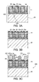
- FIG. 3a through 3c and FIGs. 4a and 4b Each sectional view shown in FIG. 3 and FIG. 4 corresponds to a sectional view along the line A-A in FIG. 1.
- the lyophilic control layer 25 made of the insulating layer is formed on the picture electrode 23 and the second interlayer insulation layer 18 as shown in FIG. 3b.
- a black matrix layer (not shown in the figures) is formed in a concave portion formed between two different picture electrodes 23 in the lyophilic control layer 25.
- the black matrix layer is formed by sputtering, for example, chromium metal in the concave portion of the lyophilic control layer 25.
- the organic bank layer 221 is formed on a predetermined position of the lyophilic control layer 25, more particularly, so as to cover the black matrix layer as shown in FIG. 3c.
- the organic bank layer is formed by forming an organic layer.
- the organic layer may be formed by, for example, applying a solution in which resist such as acrylic resin and polyimide resin is dissolved.
- the solution can be applied by a spin-coat method, a dip-coat method and the like. Any material can be adopted to form the organic layer as long as it will not dissolve in a solvent of the later-described liquid material and it is easily patterned by etching and the like.
- the organic layer is patterned by a photolithography technique or an etching technique and the opening 221a is formed in the organic layer. In this way, the organic bank layer 221 is formed.
- a lyophilic area and a lyophobic area are formed by a plasma treatment.
- the plasma treatment includes a preheating process, a lyophilic process, a lyophobic process and a cooling process.
- the lyophilic process an upper face of the organic bank layer 221, a wall surface of the opening 221a, an electrode face 23c of the picture electrode 23 and an upper face of the lyophilic control layer 25 are made to be lyophilic.
- the upper face of the organic bank layer 221 and the wall surface of the opening 221 a are made to be lyophobic.
- a treated body (a layered body composed of the picture electrode 23 and the organic bank layer 221 and the like provided on the base body 100) is heated to a predetermined temperature, for example, about 70-80 °C. Subsequently, the treated body is treated in atmosphere with the plasma treatment (the oxygen plasma treatment) by using oxygen as a reactive gas. This is the lyophilic process. Then, as the lyophobic process, another plasma treatment (CF 4 plasma treatment) using tetrafluoromethane as the reactive gas is performed. Then, the treated body that was heated in the plasma treatment is cooled down to the room temperature. In this way, the lyophilic area and the lyophobic area are respectively formed in predetermined positions.
- the plasma treatment the oxygen plasma treatment
- CF 4 plasma treatment tetrafluoromethane
- the electrode face 23c of the picture electrode 23 and the lyophilic control layer 25 will be also affected to some extent.
- ITO that is used to form the picture electrode 23, silicon oxide, titanium oxide and the like used to form the lyophilic control layer 25 have a weak affinity for fluorine. Therefore, hydroxyl given in the lyophilic process will not be replaced by fluorine group and the lyophilic area is maintained.
- the hole injection layer 70 is formed as shown in FIG. 3c.
- a thin film having a thickness of from a few nanometers to a few hundreds nanometers is formed by a liquid-phase process.
- the liquid-phase process is a method of forming a thin film by dissolving or dispersing a desired film material in a liquid and applying the liquid with the spin-coat method, the dip-method or a droplet discharging method (an ink-jet method) and the like.
- the spin-coat method and the dip-method are ideal for applying the whole surface.
- the thin film can be patterned in a desired position with the droplet discharging method.
- Such liquid-phase process is also adopted in the later-descirbed film forming processes to form the light emitting functional part, the electron injection layer, the cathode and the like.
- the hole injection layer 70 can be formed in a predetermined position without patterning by etching and the like because an electron hole transport layer forming material is applied on the electrode face 23c by the droplet discharging method.
- the hole injection layer forming material is selectively applied by the droplet discharging method (the ink-jet method).
- the hole injection layer forming material is filled in a droplet discharge head (not shown in the figures).
- a discharge nozzle of the droplet discharge head is opposed to the electrode face 23c placed in the opening 25a that is formed in the lyophilic control layer 25.
- a droplet whose volume is controlled is discharged to the electrode face 23c from the discharge nozzle while the droplet discharge head and the substrate are relatively moved.
- the droplet discharged from the discharge nozzle spreads on the electrode face 23c which is treated with the lyophilic treatment and the droplet is then filled in the opening 25a of the lyophilic control layer 25. While, the droplet is shed and will not be adhered to the upper face of the organic bank layer 221 which is treated with the lyophobic (ink) treatment. Therefore, even if the droplet is discharged afied from the predetermined position and to the upper surface of the organic bank layer 221, the upper surface will not be wet with the droplet and the shed droplet will fall into the opening 25a of the lyophilic control layer 25. In this way, the droplet is easily and precisely provided on the predetermined position.
- the hole injection layer 70 As described above, for example, PEDOT and PSS can be used as the electron hole transfer material. Furthermore, the hole injection layer 70 is not indispensable. In the above-described way, a layered body 400 including at least the anode (picture electrode) 23, the hole injection layer 70 and the organic bank layer 221 formed on the base body 100 is obtained.
- the light emitting functional part 60 is formed on the hole injection layer 70 as shown in FIG. 4a.
- the manufacturing process of the light emitting functional part 60 is the same as that of the hole injection layer 70.
- the material is discharged to a predetermined position of the hole injection layer 70 by the droplet discharging method. Then, a drying process is performed. In this way, the light emitting functional part 60 can be formed in the opening 221 a that is formed in the organic bank layer 221.
- organic substances 65 as polyvinyl carbazole, polyfluorene-based polymer derivatives, (poly)paraphenyleneVinylene derivatives, polyphenylene derivatives, polythiophene derivatives and triallylamine derivatives, such metal complex 80 as a three-coordinate iridium metal complex having 2,2'- bipyridine-4,4'-dicarboxylic acid as its ligand and such metallic compound particles 90 as zirconium oxide, titanium oxide and silicon carbide can be used.
- the polyvinyl carbazole and ADS254BE are dissolved in a nonpolar solvent such as xylene, toluene, cyclo hexyl benzene and dihydrobenzofuran. Then, the above-described zirconium oxide is added to the solution of the polyvinyl carbazole and ADS254BE. After the zirconium oxide is sufficiently dispersed, this solution is applied to the hole injection layer 70 or an anode 23 made of, for example, ITO by the liquid-phase process.
- a nonpolar solvent such as xylene, toluene, cyclo hexyl benzene and dihydrobenzofuran.
- the liquid-phase process means the method of forming a thin film by applying the liquid with the spin-coat method, the dip-method or a droplet discharging method (an ink-jet method) and the like.
- the above-described process may be performed in such way that the zirconium oxide is applied and fixed on the anode 23 made of, for example, ITO in an appropriate manner, and this is soaked in the above-described complex solution.
- the light-emitting functional part is completed by applying a polyvinyl carbazole dissolved in the above-mentioned nonpolar solvent after the soaking.
- a frame format of the light-emitting functional part is shown in FIG. 5.
- a layered body 500 including at least the anode (picture electrode) 23, the hole injection layer 70 and the light emitting functional part 60 formed on the base body 100 is obtained.
- the electron injection layer which is not shown in the figures, is formed according to need.
- an electron injection layer forming material is applied to the light emitting functional part 60 by the droplet discharging method.
- the cathode 50 is formed on the light emitting functional part 60 as shown in FIG. 4b.
- a film of a cathode material such as aluminum is formed by, for example, deposition, sputtering and the like.
- a sealing substrate 30 is formed in a sealing process.
- a film 45 having a drying capability is adhered to the inside of the sealing substrate 30.
- the sealing substrate 30 and the substrate 20 are sealed with a sealant resin (not shown in the figures) in order to prevent water and oxygen from entering into the inside of the completed organic electroluminescence element.
- a sealant resin a heat-hardening resin and an ultraviolet curing resin are used.
- this sealing process is performed in an inactive gas atmosphere such as nitrogen, argon and helium.
- the organic electroluminescence device 1 obtained through the above-described processes finely emits light from the picture electrode 23 side when a voltage of, for example, smaller than 10 V, is applied between the both electrodes.
- the cathode 50 is formed by a vapor process such as deposition, sputtering and the like in the above-described embodiment, the cathode may be formed by the liquid-phase process of using a solution or dispersion liquid containing a conductive material.
- the cathode 50 may be composed of a main cathode that is adjacent to the light emitting functional part 60 and a supplementary cathode that is put on the top of the main cathode.
- the main cathode and the supplementary cathode may be both formed of the conductive material.
- the main cathode and the supplementary cathode are both formed by the liquid-phase process such as the droplet discharging method.
- a conductive polymer material that consists of a polymer compound including, for example, ethylene dioxythiophene
- a dispersion liquid of 3,4-ethylene dioxythiophene/ polystyrene sulfonate can be used.
- the metal particle may be used instead of the conductive polymer material, or the metal particle may be used together with the conductive polymer material.
- the main cathode when the main cathode is made of the mixture material of the conductive polymer material and the metal particle, the main cathode can be calcined in relatively low temperature while the conductivity of the main cathode 50 is maintained.
- the metal particle gold, silver, aluminum and the like can be used.
- carbon paste may also be used.
- the supplementary cathode 223 is provided on the main cathode in order to enhance the conductivity of the whole cathode 50.
- the supplementary cathode 223 also protects the main cathode from oxygen and moisture by covering it and it can be made of the conductive metal particles.
- the metal particles are not especially limited as long as they are chemically stable conductive material, for example, metal and alloyed metal can be used to form them. To be more specific, aluminum, gold, silver and the like may be used.
- the cathode 50 when the cathode 50 is formed by the liquid-phase process, a vacuum environment is not necessary unlike the vapor process. Furthermore, the cathode 50 can be consecutively formed subsequently to the formation of the light emitting functional part 60. Therefore, the manufacturing process can be simplified and the productivity is raised. Furthermore, when the picture electrode (anode) is also formed by the liquid-phase process, the whole organic electroluminescence element including the anode, a functional layer (the hole injection layer, the light-emitting layer) and the cathode can be formed by the liquid-phase process. Therefore, the manufacturing process can be simplified and the productivity is raised.
- the present invention is not limited to this and can also be applied to the top-emission type and a type in which light is emitted from both top and bottom.
- the functional organic layer for example, all the hole injection layer, the organic light-emitting layer and the electron injection layer are formed by the liquid-phase process. Therefore, each layer can be more easily formed compared with a case where the each layer is formed by the vapor process.
- the electronic equipment of the present invention has the above-described organic electroluminescence device 1 as a display part.
- a cellular phone shown in FIG. 6 can be taken as an example.
- reference numeral 1000 designates a body of the cellular phone and reference numeral 1001 designates the display part which is the organic electroluminescence device I of the present embodiment. Because the cellular phone shown in FIG. 6 has the display part 1001 made of the organic electroluminescence device of the present embodiment, the cellular phone has a fine display properties.
- the electronic equipment of the preset embodiment includes a mobile information processor such as a word processor and a personal computer, a wristwatch type electronic equipment, a flat panel display (for example, television) and the like.
- the present invention is not limited to the above-described embodiments but may also be applied to a small-molecular type organic electroluminescence element.
- the present invention is not limited to this.
- the present invention may also be applied to a head of an ink-jet printer and the like.
Landscapes
- Chemical & Material Sciences (AREA)
- Engineering & Computer Science (AREA)
- Materials Engineering (AREA)
- Organic Chemistry (AREA)
- Crystallography & Structural Chemistry (AREA)
- Inorganic Chemistry (AREA)
- Electroluminescent Light Sources (AREA)
Applications Claiming Priority (2)
| Application Number | Priority Date | Filing Date | Title |
|---|---|---|---|
| JP2004109358 | 2004-04-01 | ||
| JP2004109358A JP2005294124A (ja) | 2004-04-01 | 2004-04-01 | 有機エレクトロルミネッセンス装置及び有機エレクトロルミネッセンス装置の製造方法ならびに電子機器 |
Publications (2)
| Publication Number | Publication Date |
|---|---|
| EP1583166A2 true EP1583166A2 (de) | 2005-10-05 |
| EP1583166A3 EP1583166A3 (de) | 2009-10-14 |
Family
ID=34880126
Family Applications (1)
| Application Number | Title | Priority Date | Filing Date |
|---|---|---|---|
| EP05006873A Withdrawn EP1583166A3 (de) | 2004-04-01 | 2005-03-30 | Organische Leuchtdiode mit auf ZrO2 imobilisierten Ir-Komplexen |
Country Status (6)
| Country | Link |
|---|---|
| US (1) | US20050221122A1 (de) |
| EP (1) | EP1583166A3 (de) |
| JP (1) | JP2005294124A (de) |
| KR (1) | KR100692461B1 (de) |
| CN (1) | CN1678152A (de) |
| TW (1) | TWI303534B (de) |
Cited By (1)
| Publication number | Priority date | Publication date | Assignee | Title |
|---|---|---|---|---|
| EP1696017A1 (de) * | 2005-02-25 | 2006-08-30 | Seiko Epson Corporation | Lichtemittierendes Material, Vorrichtung und elektronischer Apparat |
Families Citing this family (7)
| Publication number | Priority date | Publication date | Assignee | Title |
|---|---|---|---|---|
| WO2006132128A1 (ja) * | 2005-06-06 | 2006-12-14 | Sharp Kabushiki Kaisha | 正孔注入輸送層用塗液、正孔注入輸送層の製造方法、有機エレクトロルミネセンス素子、及び、その製造方法 |
| US7476603B2 (en) * | 2005-06-07 | 2009-01-13 | Hewlett-Packard Development Company, L.P. | Printing conductive patterns using LEP |
| JP4923610B2 (ja) * | 2006-02-16 | 2012-04-25 | コニカミノルタホールディングス株式会社 | 有機エレクトロルミネッセンス素子、表示装置及び照明装置 |
| CN101919082B (zh) * | 2007-12-28 | 2012-05-30 | 夏普株式会社 | 有机电致发光元件 |
| US20100283045A1 (en) * | 2007-12-28 | 2010-11-11 | Hideki Uchida | Organic electroluminescent element |
| JP5761199B2 (ja) * | 2010-10-22 | 2015-08-12 | コニカミノルタ株式会社 | 有機エレクトロルミネッセンス素子 |
| EP2666829B1 (de) * | 2011-01-19 | 2019-07-10 | Sumitomo Osaka Cement Co., Ltd. | Organisch-anorganische verbindung und zusammensetzung sowie tinte mit der organisch-anorganischen verbindung |
Family Cites Families (48)
| Publication number | Priority date | Publication date | Assignee | Title |
|---|---|---|---|---|
| US1756361A (en) * | 1926-09-11 | 1930-04-29 | Jefferson Electric Co | Outlet-box mounting |
| JPS5641291A (en) | 1979-09-14 | 1981-04-17 | Hitachi Ltd | El panel and production thereof |
| SE506019C2 (sv) * | 1994-05-17 | 1997-11-03 | Forskarpatent I Linkoeping Ab | Ljuskälla av konjugerade polymerer med spänningsstyrd färg samt metod för tillverkning av ljuskällan |
| US5623789A (en) * | 1994-09-12 | 1997-04-29 | Kidwell; Steven A. | Pitch stabilizing, positionable eaves-overhang light support assembly |
| US5873556A (en) * | 1995-03-13 | 1999-02-23 | Reiker; Kenneth H. | Adjustable drop ceiling fixture support |
| US5678799A (en) * | 1995-06-07 | 1997-10-21 | Hubbell Incorporated | Adjustable hanger assembly |
| US5690423A (en) * | 1996-03-04 | 1997-11-25 | Nsi Enterprises, Inc. | Wire frame pan assembly for mounting recessed lighting in ceilings and the like |
| CA2250945C (en) * | 1996-04-12 | 2005-02-15 | Powerwall, Inc. | Integrally powered modular furniture |
| US5662414A (en) * | 1996-05-03 | 1997-09-02 | Nsi Enterprises, Inc. | Thermoplastic pan assembly for mounting recessed lighting fixtures in ceilings and the like |
| US5758959A (en) * | 1996-05-17 | 1998-06-02 | Progress Lighting, Inc. | Recessed lamp fixture |
| JP3631845B2 (ja) * | 1996-06-11 | 2005-03-23 | セイコープレシジョン株式会社 | 有機el素子 |
| DE19625993A1 (de) * | 1996-06-28 | 1998-01-02 | Philips Patentverwaltung | Organisches elektrolumineszentes Bauteil mit Ladungstransportschicht |
| US5845886A (en) * | 1996-07-26 | 1998-12-08 | Mccormick; Henry | Adjustable ceiling fan support assembly |
| US5934631A (en) * | 1996-08-19 | 1999-08-10 | Thomas & Betts Corporation | Hanger bar assembly |
| US6296211B1 (en) * | 1996-10-15 | 2001-10-02 | Snyder National Corporation | Duct and pipe bracket for use between joists |
| US5954304A (en) * | 1996-10-25 | 1999-09-21 | Hubbell Incorporated | Adjustable hanger assembly |
| US5746507A (en) * | 1997-01-06 | 1998-05-05 | Thomas Industries, Inc. | Recessed lighting fixture for two light sizes |
| US5958573A (en) * | 1997-02-10 | 1999-09-28 | Quantum Energy Technologies | Electroluminescent device having a structured particle electron conductor |
| US6082878A (en) * | 1998-02-03 | 2000-07-04 | Cooper Industries, Inc. | Fully rotatable recessed light fixture with movable stop and adjustable length bar hanger |
| US6098945A (en) * | 1998-03-19 | 2000-08-08 | Hubbell Incorporated | Mounting bracket and supporting brace |
| US6105918A (en) * | 1998-04-24 | 2000-08-22 | Cooper Technologies Company | Single piece adjustable hanger bar for lighting fixtures |
| US6076788A (en) * | 1998-06-22 | 2000-06-20 | Cooper Industries | Reinforced hanger bar |
| GB9815271D0 (en) * | 1998-07-14 | 1998-09-09 | Cambridge Display Tech Ltd | Particles and devices comprising particles |
| US6231205B1 (en) * | 1998-10-23 | 2001-05-15 | Powerwall, Inc. | Illuminated shelving |
| JP4505067B2 (ja) | 1998-12-16 | 2010-07-14 | 淳二 城戸 | 有機エレクトロルミネッセント素子 |
| US6164802A (en) * | 1998-12-23 | 2000-12-26 | Cooper Technologies Company | Stackable housing |
| US6030102A (en) * | 1998-12-23 | 2000-02-29 | Cooper Technologies Company | Trim retention system for recessed lighting fixture |
| US6468676B1 (en) | 1999-01-02 | 2002-10-22 | Minolta Co., Ltd. | Organic electroluminescent display element, finder screen display device, finder and optical device |
| EP1729327B2 (de) * | 1999-05-13 | 2022-08-10 | The Trustees Of Princeton University | Verwendung einer phosphoreszierenden Iridiumverbindung als Emissionsmolekül in einer organischen lichtemittierenden Vorrichtung |
| US6286265B1 (en) * | 2000-02-01 | 2001-09-11 | Cooper Technologies Company | Recessed lighting fixture mounting |
| US6565994B2 (en) * | 2000-02-10 | 2003-05-20 | Fuji Photo Film Co., Ltd. | Light emitting device material comprising iridium complex and light emitting device using same material |
| US6431723B1 (en) * | 2000-04-28 | 2002-08-13 | Cooper Technologies, Company | Recessed lighting fixture |
| EP1297060B2 (de) * | 2000-06-12 | 2012-04-04 | Sumitomo Chemical Company Limited | Elektrolumineszierende materialien und gegenstände aus einer polymermatrix |
| US6471374B1 (en) * | 2000-06-30 | 2002-10-29 | Genlyte Thomas Group Llc | Accent light adjustable assembly |
| US6484980B2 (en) * | 2000-07-21 | 2002-11-26 | Lewis B. Medlin, Sr. | Field bendable tab for electrical box support |
| US6688069B2 (en) * | 2000-07-24 | 2004-02-10 | Unimast Incorporated | Vertical slide clip |
| US6461016B1 (en) * | 2000-10-25 | 2002-10-08 | Hubbell Incorporated | Adjustable recessed downlight |
| US6515314B1 (en) * | 2000-11-16 | 2003-02-04 | General Electric Company | Light-emitting device with organic layer doped with photoluminescent material |
| US6805916B2 (en) * | 2001-01-17 | 2004-10-19 | Research Foundation Of The City University Of New York | Method for making films utilizing a pulsed laser for ion injection and deposition |
| US6787063B2 (en) * | 2001-03-12 | 2004-09-07 | Seiko Epson Corporation | Compositions, methods for producing films, functional elements, methods for producing functional elements, methods for producing electro-optical devices and methods for producing electronic apparatus |
| US6505960B2 (en) * | 2001-03-19 | 2003-01-14 | Cooper Industries, Inc. | Recessed lighting fixture locking assembly |
| US6519791B2 (en) * | 2001-07-03 | 2003-02-18 | Securus, Inc. | Stub-out bar |
| JP4217013B2 (ja) * | 2001-11-13 | 2009-01-28 | 株式会社林原生物化学研究所 | 吸光組成物 |
| US6609690B1 (en) * | 2001-12-05 | 2003-08-26 | Terabeam Corporation | Apparatus for mounting free space optical system equipment to a window |
| US6637705B2 (en) * | 2002-01-22 | 2003-10-28 | The United States Of America As Represented By The Secretary Of The Navy | Flow meter strut |
| JP2003257671A (ja) * | 2002-02-28 | 2003-09-12 | Fuji Photo Film Co Ltd | 発光素子及びその製造方法 |
| US6691968B1 (en) * | 2002-09-03 | 2004-02-17 | L & C Lighting Enterprise Co., Ltd. | Bracket for a recessed light |
| WO2004112440A1 (ja) * | 2003-06-13 | 2004-12-23 | Matsushita Electric Industrial Co., Ltd. | 発光素子及びその製造方法、表示装置 |
-
2004
- 2004-04-01 JP JP2004109358A patent/JP2005294124A/ja not_active Withdrawn
-
2005
- 2005-03-03 KR KR1020050017587A patent/KR100692461B1/ko not_active Expired - Fee Related
- 2005-03-15 TW TW094107902A patent/TWI303534B/zh not_active IP Right Cessation
- 2005-03-16 CN CNA2005100548002A patent/CN1678152A/zh active Pending
- 2005-03-28 US US11/090,854 patent/US20050221122A1/en not_active Abandoned
- 2005-03-30 EP EP05006873A patent/EP1583166A3/de not_active Withdrawn
Cited By (2)
| Publication number | Priority date | Publication date | Assignee | Title |
|---|---|---|---|---|
| EP1696017A1 (de) * | 2005-02-25 | 2006-08-30 | Seiko Epson Corporation | Lichtemittierendes Material, Vorrichtung und elektronischer Apparat |
| US7737454B2 (en) | 2005-02-25 | 2010-06-15 | Seiko Epson Corporation | Organic light-emitting element, organic light-emitting device, and electronic apparatus |
Also Published As
| Publication number | Publication date |
|---|---|
| US20050221122A1 (en) | 2005-10-06 |
| JP2005294124A (ja) | 2005-10-20 |
| CN1678152A (zh) | 2005-10-05 |
| EP1583166A3 (de) | 2009-10-14 |
| KR20060043359A (ko) | 2006-05-15 |
| KR100692461B1 (ko) | 2007-03-09 |
| TW200541389A (en) | 2005-12-16 |
| TWI303534B (en) | 2008-11-21 |
Similar Documents
| Publication | Publication Date | Title |
|---|---|---|
| US7301277B2 (en) | Electro-optical apparatus, manufacturing method thereof, and electronic instrument | |
| US8197295B2 (en) | Production apparatus and method of producing a light-emitting device by using the same apparatus | |
| TWI338186B (de) | ||
| US7115904B2 (en) | Method of manufacturing organic electroluminescent device, organic electroluminescent device, substrate for organic electroluminescent device, and electronic apparatus | |
| CN100447983C (zh) | 显示装置的制造方法 | |
| US8624233B2 (en) | Organic electroluminescence display device and electronic apparatus | |
| WO2017098758A1 (ja) | 光学式指紋認証装置 | |
| US7514115B2 (en) | Method of forming thin film of organometallic compound, thin film of organometallic compound, method of manufacturing organoelectronic device equipped with the same, organoelectronic device, method of manufacturing organic electroluminescence, organic electroluminescence, and electronic apparatus | |
| JP2006093123A (ja) | 発光素子用の基板、その製造方法、発光素子用の電極、及びこれを備えた発光素子 | |
| EP1583166A2 (de) | Organische Leuchtdiode mit auf ZrO2 imobilisierten Ir-Komplexen | |
| KR100662835B1 (ko) | 일렉트로루미네선스 장치 및 일렉트로루미네선스 장치의제조 방법 및 전자 기기 | |
| JP4345267B2 (ja) | 電気光学装置及びその製造方法、並びに電子機器 | |
| JP4240017B2 (ja) | 発光装置及び電子機器 | |
| JP4411828B2 (ja) | 電気光学装置及びその製造方法、並びに電子機器 | |
| KR100706853B1 (ko) | 유기 일렉트로루미네선스 장치 및 이의 제조 방법 | |
| JP2004171943A (ja) | 発光装置の作製方法 | |
| JP2004171941A (ja) | 発光装置の作製方法 | |
| JP2004071395A (ja) | 電気光学装置及びその製造方法、並びに電子機器 | |
| JP4622357B2 (ja) | 有機el装置および電子機器 | |
| JP4770523B2 (ja) | 発光装置の製造方法 | |
| JP2005158489A (ja) | 有機el装置とその製造方法及び電子機器 | |
| JP2004063138A (ja) | 電気光学装置及びその製造方法、並びに電子機器 |
Legal Events
| Date | Code | Title | Description |
|---|---|---|---|
| PUAI | Public reference made under article 153(3) epc to a published international application that has entered the european phase |
Free format text: ORIGINAL CODE: 0009012 |
|
| AK | Designated contracting states |
Kind code of ref document: A2 Designated state(s): AT BE BG CH CY CZ DE DK EE ES FI FR GB GR HU IE IS IT LI LT LU MC NL PL PT RO SE SI SK TR |
|
| AX | Request for extension of the european patent |
Extension state: AL BA HR LV MK YU |
|
| PUAL | Search report despatched |
Free format text: ORIGINAL CODE: 0009013 |
|
| AK | Designated contracting states |
Kind code of ref document: A3 Designated state(s): AT BE BG CH CY CZ DE DK EE ES FI FR GB GR HU IE IS IT LI LT LU MC NL PL PT RO SE SI SK TR |
|
| AX | Request for extension of the european patent |
Extension state: AL BA HR LV MK YU |
|
| AKX | Designation fees paid | ||
| STAA | Information on the status of an ep patent application or granted ep patent |
Free format text: STATUS: THE APPLICATION IS DEEMED TO BE WITHDRAWN |
|
| 18D | Application deemed to be withdrawn |
Effective date: 20100415 |
|
| REG | Reference to a national code |
Ref country code: DE Ref legal event code: 8566 |