EP1581076B1 - System und verfahren zur herstellung eines anpassbaren künstlichen fingernagels mit einer kontaktlosen optischen messvorrichtung - Google Patents
System und verfahren zur herstellung eines anpassbaren künstlichen fingernagels mit einer kontaktlosen optischen messvorrichtung Download PDFInfo
- Publication number
- EP1581076B1 EP1581076B1 EP03783459A EP03783459A EP1581076B1 EP 1581076 B1 EP1581076 B1 EP 1581076B1 EP 03783459 A EP03783459 A EP 03783459A EP 03783459 A EP03783459 A EP 03783459A EP 1581076 B1 EP1581076 B1 EP 1581076B1
- Authority
- EP
- European Patent Office
- Prior art keywords
- fingernail
- artificial
- artificial fingernail
- dimensional
- natural
- Prior art date
- Legal status (The legal status is an assumption and is not a legal conclusion. Google has not performed a legal analysis and makes no representation as to the accuracy of the status listed.)
- Expired - Lifetime
Links
- 210000004905 finger nail Anatomy 0.000 title claims abstract description 233
- 238000000034 method Methods 0.000 title claims abstract description 43
- 230000003287 optical effect Effects 0.000 title claims abstract description 12
- 238000013461 design Methods 0.000 claims abstract description 27
- 238000003754 machining Methods 0.000 claims abstract description 24
- 238000012876 topography Methods 0.000 claims abstract description 23
- 239000000463 material Substances 0.000 claims description 21
- 238000005520 cutting process Methods 0.000 claims description 6
- 238000004364 calculation method Methods 0.000 claims description 3
- 238000003801 milling Methods 0.000 claims 1
- 238000012634 optical imaging Methods 0.000 claims 1
- 210000000282 nail Anatomy 0.000 abstract description 54
- 239000002994 raw material Substances 0.000 abstract description 2
- 238000004590 computer program Methods 0.000 abstract 1
- 238000004519 manufacturing process Methods 0.000 description 10
- 239000011248 coating agent Substances 0.000 description 9
- 238000000576 coating method Methods 0.000 description 9
- 238000007641 inkjet printing Methods 0.000 description 7
- 238000005259 measurement Methods 0.000 description 5
- 238000010586 diagram Methods 0.000 description 4
- 239000000853 adhesive Substances 0.000 description 2
- 230000001070 adhesive effect Effects 0.000 description 2
- 239000004744 fabric Substances 0.000 description 2
- 238000003384 imaging method Methods 0.000 description 2
- 230000002093 peripheral effect Effects 0.000 description 2
- 238000003860 storage Methods 0.000 description 2
- 229920001187 thermosetting polymer Polymers 0.000 description 2
- 229920002799 BoPET Polymers 0.000 description 1
- 239000005041 Mylar™ Substances 0.000 description 1
- NIXOWILDQLNWCW-UHFFFAOYSA-N acrylic acid group Chemical group C(C=C)(=O)O NIXOWILDQLNWCW-UHFFFAOYSA-N 0.000 description 1
- 239000012790 adhesive layer Substances 0.000 description 1
- 238000005266 casting Methods 0.000 description 1
- 239000003795 chemical substances by application Substances 0.000 description 1
- 239000003086 colorant Substances 0.000 description 1
- 238000012790 confirmation Methods 0.000 description 1
- 238000012938 design process Methods 0.000 description 1
- 238000000605 extraction Methods 0.000 description 1
- 239000000945 filler Substances 0.000 description 1
- 239000003517 fume Substances 0.000 description 1
- 238000001746 injection moulding Methods 0.000 description 1
- 238000007689 inspection Methods 0.000 description 1
- 239000010410 layer Substances 0.000 description 1
- 239000007788 liquid Substances 0.000 description 1
- 230000007257 malfunction Effects 0.000 description 1
- 239000002184 metal Substances 0.000 description 1
- 238000012986 modification Methods 0.000 description 1
- 230000004048 modification Effects 0.000 description 1
- 239000003973 paint Substances 0.000 description 1
- 239000011505 plaster Substances 0.000 description 1
- 239000004033 plastic Substances 0.000 description 1
- 229920003023 plastic Polymers 0.000 description 1
- 230000000241 respiratory effect Effects 0.000 description 1
- 238000007493 shaping process Methods 0.000 description 1
- 239000000126 substance Substances 0.000 description 1
- 238000004441 surface measurement Methods 0.000 description 1
- 210000004906 toe nail Anatomy 0.000 description 1
- 230000001131 transforming effect Effects 0.000 description 1
- 238000013519 translation Methods 0.000 description 1
- 125000000391 vinyl group Chemical group [H]C([*])=C([H])[H] 0.000 description 1
- 229920002554 vinyl polymer Polymers 0.000 description 1
Images


Classifications
-
- A—HUMAN NECESSITIES
- A45—HAND OR TRAVELLING ARTICLES
- A45D—HAIRDRESSING OR SHAVING EQUIPMENT; EQUIPMENT FOR COSMETICS OR COSMETIC TREATMENTS, e.g. FOR MANICURING OR PEDICURING
- A45D31/00—Artificial nails
Definitions
- the present invention generally relates to creating custom fit artificial fingernails and specifically to a process and system for creating custom fit artificial fingernails using a non-contact measuring device for measuring a fingernail for custom fitting an artificial fingernail.
- Artificial fingernail tips a desirable fashion (if not also functional) accessory, exist in various forms.
- a customized artificial fingernail can be made to fit the exact contour and dimensions of a natural fingernail. This offers considerable advantages in comfort, appearance, and durability over non-custom fit fingernails commonly available.
- custom fitting an artificial fingernail poses special challenges and problems. Commonly used methods for production of artificial fingernails are very labor intensive, time consuming and require significant skill.
- thermoset material mainly acrylic type
- This process is repeated for each finger.
- intensive and abrasive filing is applied to create a desired shape for each fingernail. Since this method builds up an artificial fingernail by adding material little by little manually, it gained the name of "nail sculpture.” The last step of this process is to paint the top surface of the artificial fingernails with nail polish to display the desired color or pattern.
- nail wrapping Another method to create artificial fingernails is called "nail wrapping.”
- fabric pieces are cut off and glued onto a natural fingernail. After a few layers of fabric are glued and dried, coats of filler material are applied to create a continuous uniform surface. After intensive filing to the desired shape, the nail can be polished. This process has to be repeated on each finger.
- Both nail sculpturing and nail wrapping expose the user and nail technicians to fumes, chemical liquids, and filing debris, which can present health and respiratory problems.
- the growth of a natural nail will create a gap between its cuticle and applied artificial fingernail since the artificial fingernail, once applied, is bonded onto the natural nail surface. This gap needs to be filled regularly, and this process requires a great deal of time and money.
- a less expensive alternative to the nail sculpturing and nail wrapping methods is the pre-made artificial fingernail tips with nail art already in place that are capable of being pasted onto the natural fingernail.
- mass-produced artificial fingernail tips have limited choices in their shapes, lengths, styles and fit.
- a person's fingernail is different from another person's in its cuticle, width, length, and three-dimensional (3D) shape. Therefore, mass-produced artificial fingernail tips cannot fit exactly to a user's natural fingernail.
- such an artificial fingernail tip is forced onto a natural fingernail surface, and glued on with an adhesive. This poses the problem that such an artificial fingernail tip can be peeled easily.
- this type of artificial fingernail tip is usually recognized as false due to the unfitted shape at the margins.
- Another option that solves the problems encountered in the existing pre-made artificial fingernail tips and the nail sculpturing and nail wrapping methods as described above, is to custom manufacture every artificial fingernail tip.
- This process may consist of creating a plaster mold from a series of precise impressions of a natural fingernail, then the mold can be used to create an artificial fingernail by either injection molding or casting.
- the creation of artificial nails by using this process is still time consuming, costly and requires considerable work to turn the rough cast into the finished product. It is also impractical to perform this process in a nail salon environment.
- EP 0 577 515 discloses a system using information taken from a sensing device sensing the dimensions of an existing fingernail structure and inputting this sensed information into a controller in machine usable form. The data is used by the controller to drive a variety of peripheral devices to cut a desired nail pattern in a material so that at least a part of the material snugly fits over the existing nail structure. The system is further capable of cutting a sheet of decorative material to the shape of a natural nail or one that is artificially placed on a nail.
- the decorative sheet may be formed of vinyl or mylar and has an adhesive layer which binds it to the involved nail.
- US 6,035,860 discloses a system for applying artwork to fingernails having a computer controller, a hand mold to securely hold the user's fingernails, a device for determining the size and location of the fingernails, and an applicator for applying the artwork.
- a method for applying artwork to fingernails provides color and/or design choices selected from a computer media catalogue of colors and designs. A user views these choices on a video monitor, which also displays messages to guide the user through the application process. Prior to application of the artwork, the fingernails are coated with a light reactive base coat.
- the user's hands are inserted into a hand mold in which a height sensor and height gauge aid in positioning the fingernails at a preferred height position.
- the hand mold is retracted into a main system module in which an optical sensor detects the light reactive base coating for determining the size, peripheral shape, and location of the fingernails.
- a color applicator in the main system module applies the user selected artwork directly to the user's fingernails.
- US 6,328,949 discloses a method for making nail coverings comprising the steps of scanning a persons fingernail to produce a digitized nail image of the nail top surface and shaping a nail covering material using the digitized nail image such that the nail covering material conforms to the nail top surface thereby producing a nail cover sized to cover substantially the entire nail top surface.
- the method preferably includes the step of adhering the nail cover to the nail top surface thereby covering substantially the entire nail top surface with the nail cover.
- the method preferably includes the further step of producing a three dimensional digital nail image of the nail top surface.
- a preferred embodiment provides an artificial fingernail production system for creating custom fit artificial fingernails.
- the system comprises a non-contact measuring system for measuring dimensions of a fingernail wherein the non-contact measuring system comprises a non-contact measuring device for measuring a three-dimensional topography of a fingernail.
- a further aspect of the present invention employs a machining device for creating an artificial fingernail using the three-dimensional topography of the fingernail wherein the resulting artificial fingernail custom fits the fingernail.
- Yet another aspect of the present invention provides a light source for emitting a white light onto the fingernail and a camera for recording an image of the fingernail.
- the light source may project a grid onto the fingernail and take a picture of the grid for calculating the three-dimensional topography.
- a laser can be used as the light source for scanning the surface of the fingernail. Data from either the white light embodiment or the laser embodiment of the light source is converted into a three-dimensional topographical data structure for the fingernail.
- a preferred embodiment provides a process for custom designing an artificial fingernail comprising the steps of measuring a three-dimensional topography of a fingernail with a non-contact measuring system, selecting parameters for the artificial fingernail wherein the parameters include thickness, length and style of the artificial fingernail, and then calculating a three-dimensional shape of the artificial fingernail from the three-dimensional topography of the fingernail and the parameters for the artificial fingernail.
- this process also includes machining the artificial fingernail for custom fitting the fingernail.
- a system user for one aspect of the present invention presents a finger or fingers for custom measuring where a non-contact measuring device measures the topography of the fingernail for each finger. This can then be repeated for each other finger or fingers as desired.
- the resulting data from the measurement is converted into a three-dimensional image for viewing by the user together with a proposed artificial fingernail.
- the user is then allowed to select options for designing a customized artificial fingernail. Once the desired options are selected the three-dimensional data for the artificial fingernail is converted into a machine code and transferred to a machine such as a computer numerically controlled machine for cutting the artificial fingernail from a raw material into the desired shape that provides a custom fit to the system user.
- a system and process for quickly and accurately measuring and custom fitting artificial fingernails.
- the system offers the opportunity of measuring for, designing, and producing custom fingernails within a short period of time.
- the system is advantageously small and suitable for use in a salon where custom fingernail design is already offered.
- an advantage of the present invention is to provide a system and process for creating custom crafted artificial fingernail tips by using an automated system with a non-contact measuring system.
- a further advantage of the invention is to provide a safe, convenient, accurate, and rapid system for measuring the topographical shape and dimensions of a natural fingernail and producing a custom fit artificial fingernail. It is yet a further advantage of the present invention to provide a method to digitally design an artificial fingernail incorporating the digitized three-dimensional shape of a natural fingernail.
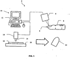
- Figure 1 is a diagrammatic view schematically illustrating the preferred embodiment of the artificial fingernail production system of the present invention
- Figure 2 is a diagrammatic view illustrating components of a measuring system of the present invention system
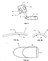
- Figure 3A is a cross sectional view along the nail length direction of an artificial fingernail of the present invention system
- Figure 3B is a cross sectional view along the nail width direction of the artificial fingernail of the present invention system
- Figure 3C is a top elevational view of the artificial fingernail of the present invention system
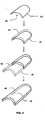
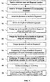
- Figure 4 is a diagrammatic view illustrating the steps employed in the process of the present invention system for digitally creating artificial fingernails
- Figure 5 is a diagrammatic view illustrating the steps of creating CNC machine usable codes in the present invention system
- Figure 6 is a flow diagram of the measurement process of the present invention system for measuring a natural fingernail
- Figure 7 is a flow diagram of the computer logic employed in the present invention system for how to design the shape of the artificial fingernail;
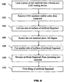
- Figure 8 is a flow diagram of the machining process of the present invention system for the artificial fingernails.
- Figure 9 is a flow diagram of applying nail polish or creating nail art onto the artificial fingernail of the present invention system.
- an artificial fingernail production system 2 of the present invention comprises an optical measuring device 4 for measuring the topography and dimensions of a fingernail 6 of a finger 8.
- the optical measuring device 4 is of the type known by those skilled in the relevant art.
- the optical measuring device may be the type as disclosed in U.S. Patent No. 5,175,601 , entitled High-Speed 3-D Surface Measurement Surface Inspection and Reverse-CAD System.
- the optical measuring device 4 is connected to a measuring and design system 10 comprising a computer system 12.
- the measuring and design system 10 is connected to a machining device 14 with a machining tool 16 for machining a material 18 that is mounted on a base 20 into an artificial fingernail 22.
- the machining device 14 in an embodiment, is a computer-numerically-controlled (CNC) device such as known by those skilled in the relevant art.
- the machining device 14 may be of the type that is disclosed in U.S. Patent No. 5,493,502 , entitled Numerical Control Unit for Controlling a Machine Tool to Machine a Workpiece at an Instructed Along Linear and Rotational Axes.
- the computer system 12 comprises a microprocessor based computer attached to a monitor, keyboard and pointing device, for example, a mouse.
- the computer has storage devices for example a hard drive and RAM for storing and reading application programs and data.
- the optical measuring device 4 of the artificial fingernail production system 2 comprises a camera 24, a light source 26 and a projection lens 28.
- the camera 24 is either an analog or digital video camera with an imaging capability as an area type or line type imager.
- the light source 26 is a white light for projecting a grid (not shown) onto the fingernail 6. While the grid is projected onto the fingernail 6, the camera 24 is used to take a picture or pictures of the grid. The picture or pictures are then transferred to the measuring and design system 10 for calculating the three-dimensional topography of the fingernail 6.
- the light source 26 is a laser used to measure the three-dimensional topography of the fingernail 6.
- the laser light source 26 scans a stripe across the fingernail 6 and the camera 24 records the image.
- a laser triangulation algorithm is then used to determine the three-dimensional topography of the fingernail 6.
- the laser scanning can be achieved by translating the light source 26 or by shifting the fingernail 6.
- Other ways of scanning the fingernail 6 with a laser light source 26 can alternately be used including by rotating a mirror (not shown) for rotatably scanning the laser across the fingernail 6 without movement of the light source 26.
- the imaging and scanning process are advantageously brief, allowing a user of the artificial fingernail production system 2 to quickly scan and measure the three-dimensional topography of a plurality of fingernails.
- the grid that is projected onto the fingernail 6 will deform in accordance with the topography of the fingernail 6.
- the deformations of the grid of the fingernail 6 are recorded by the camera 24 as a two-dimensional grid image.
- Different algorithms can be used to decode this two-dimensional deformed grid image into a three-dimensional topography of the fingernail 6.
- Algorithms for decoding the two-dimensional deformed grid image include: phase shifting; Fourier transforming; spatial coding; and Sinusoidal fitting. These algorithms will provide a phase map at the end of the calculation which is converted into three-dimensional coordinates for each pixel of the grid image. These calculations are performed by the measuring and design system 10.
- Both the laser scanning and white light grid methods will generate a set of points with known x, y, and z axis coordinates to represent the three-dimensional topography of the fingernail 6.
- the x, y, and z coordinates also define the boundary between the finger 8 and the fingernail 6.
- the x, y, and z axis coordinates are saved in the computer system's 12 storage capacity in a digital format.
- the boundary of the fingernail 6 can be determined by one of the following ways: (1) drawing an outline of the fingernail 6 of the finger 8 on the screen of the computer monitor by using the pointing device; or (2) automatically determining the boundary of the fingernail 6 by a boundary extraction algorithm. Both methods are well known to those skilled in the relevant art.
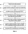
- the process for creating a custom fit artificial fingernail with a non-contact measuring device starts in step 60 with the treatment of the fingernail 6 to allow a more accurate measurement of the fingernail 6. This involves removing excess cuticle and cutting the fingernail 6 to an appropriate length.
- the fingernail 6 is covered with a coating.
- the coating is applied to create an optically diffusive surface on the fingernail 6.
- Any suitable coating can be used.
- a suitable coating is SKD-S2 from MagnaFluxTM. Step 62 of applying the coating on the fingernail 6 is not required and can be omitted.
- step 63 the fingernail 6 is placed in the optical measuring device 4 for measuring the three-dimensional topography of the fingernail 6.
- the optical measuring device 4 is then activated in step 64 and in step 65 the optical measuring device 4 takes an image of the fingernail 6 with the camera 24 while a grid or laser beam is projected onto the fingernail 6.
- step 66 the measuring and design system 10 calculates x, y, and z coordinates for the fingernail 6.
- step 67 the calculated coordinates are saved to the computer system 12 of the measuring and design system 10.
- the artificial fingernail 22 will have at least a portion of its undersurface that matches at least a portion of the corresponding fingernail 6.
- the artificial fingernail 22 has an underside 30 (with a solid line representing the portion that conforms to the topographical surface of the fingernail 6).
- a top side 32 of the artificial fingernail 22 (shown in broken line) corresponds to the portion of the artificial fingernail 22 that is custom designed as part of the processes of the invention.
- a back 34 and side 36 of the artificial fingernail 22 match the outer boundary of the fingernail 6 on the finger 8. Since only the underside 30 of the artificial fingernail 22 matches the three-dimensional topography of the fingernail 6 the remaining portion may be advantageously designed in whatever shape is desired.
- a design process is used to carry out the digital design of the artificial fingernail 22.
- This includes a first step 70 of inputting a customer name and fingernail number into the measuring and design system 10 for matching to and uniquely identifying the three-dimensional topographical measurement of the fingernail 6.
- step 72 the three-dimensional topographical information of the fingernail 6 is then selected.
- a desired thickness in step 74 and a length in step 76 of the artificial fingernail 22 are selected.
- the design profiles for the top side 32 of the artificial fingernail 22 in both nail length, in step 78, and width, in step 80, directions are selected.
- the style in step 82 of the artificial fingernail 22 is selected. With the information selected pursuant to steps 74-82 the artificial fingernail shape can be calculated in step 84 based on the input parameters and the three-dimensional topographical data for the fingernail 6.
- Figure 4 illustrates the steps for creating a three-dimensional data structure for the artificial fingernail 22. Illustrated first is a representation of the three-dimensional topographical data 42 that defines the topography of the fingernail 6. A top surface 44 is created from this based on the selected thickness and the chosen top surface profiles in both nail length and width directions. Next, the top surface 44 and the underside 30 formed from the three-dimensional topographical data 42 are used to define an extended top surface 46 and an extended undersurface 48. This step completes the process to create an artificial fingernail 22 which now has an integral extended top surface 46.
- the design system 40 will use the three-dimensional data structure of the resulting three-dimensional model of the artificial fingernail 22 to generate machine usable codes for machining an artificial fingernail as indicated in step 90.
- a machining process of the artificial fingernail production system 2 starts with providing a material 18 for machining.
- a series of cross-sectional lines 50 are generated along either the intended nail width or nail length direction at a predetermined spacing.
- the best position of the machining tool 16 is calculated at certain step sizes to create a three-dimensional cutter path 52.
- the three-dimensional cutter path 52 data is saved as a series of codes in a form readable by a machining device 14 such as a CNC machine.
- the material 18 for making the artificial fingernail 22 can advantageously be any desirable and suitable plastic, metal or other material.
- the machining device 14 will have at least three motor-driven translation axes perpendicular to each other.
- the machining tool 16 is capable of being controllably positioned along at least two perpendicular directions.
- the material 18 is provided in a rectangular shape with a length, width and height sufficient to accommodate the finished artificial fingernail 22. Referring to Figure 8 , in a first step 100 of the machining process, the material 18 is loaded into the machine device 14 (the CNC machine). Next, in step 102, machine usable codes created in step 90 are received by the machining device 14. Next, in step 104, one side of the surface of the material 18 for the artificial fingernail 22 is cut.
- step 106 This is followed in step 106 by rotating the material 18, 180 degrees for cutting, in step 108, the other side of the artificial fingernail 22.
- step 104 and step 108 two dimensional or three dimensional decorative designs or indicia, e.g. numbers, letters, etc., can be machined.
- the artificial fingernail 22 is next released from any remaining material 18 in step 110.
- step 112 any necessary finish filing of the artificial fingernail 22 is performed.
- an artificial fingernail 22 of the artificial fingernail production system 2 is produced.
- the artificial fingernail can next be coated with a design using an inkjet printing apparatus.
- the inkjet printing apparatus can be for example an inkjet printer by ImagiNailTM Corporation.
- a base coat is applied on the top surface of the artificial fingernail 22 before any nail art can be printed by using an inkjet printing apparatus.
- the base coating is used as a color-receiving agent to prevent ink from smearing.
- the artificial fingernail can be loaded into the inkjet printing apparatus.
- Desired nail art has to be chosen from a digital nail art collection saved on the computer system 12. Alternatively, nail art can be provided in a digital picture format in step 126.
- the inkjet printing apparatus will sense the size and position of the loaded artificial fingernail in step 124, and will resize the chosen nail art to match the size of the artificial fingernail in step 128. After confirmation, the nail art can be printed out onto the artificial fingernail surface in step 130.
- the inkjet printing apparatus has at least two motor-driven axes, and multiple color ink tanks. After removing the artificial fingernail from the inkjet printing apparatus in step 132, the final step is to apply a clear coating on the artificial fingernail to protect the nail art in step 134.
Claims (14)
- System (2) zum Schaffen eines maßgeschneiderten, dreidimensionalen, künstlichen Fingernagels (22), wobei ein Teil des künstlichen Fingernagels (22) eine Form behält, die im Wesentlichen der oberen Fläche eines natürlichen Fingernagels (6) entspricht, wobei das System (2) umfasst:ein berührungsloses Messsystem (4) zum Messen einer dreidimensionalen Topografie des natürlichen Fingernagels (6), wobei das Messsystem (4) eine Lichtquelle (26) und eine Kamera (24) umfasst;ein Entwurfsystem (10) zum Entwerfen der dreidimensionalen Form des künstlichen Fingernagels (22) durch Anbieten einer Auswahl von Parametern, umfassend die Länge und die dreidimensionale Ausführung des künstlichen Fingernagels (22);ein Rechenmodul (12) als Teil des Entwurfsystems (10) zum Berechnen eines dreidimensionalen Entwurfs des künstlichen Fingernagels (22) auf der Grundlage der dreidimensionalen Topografie des natürlichen Fingernagels (6) und der ausgewählten Parameter; undeine Bearbeitungsvorrichtung (14) zum Schaffen des künstlichen Fingernagels (22) unter Verwendung des dreidimensionalen Entwurfs des künstlichen Fingernagels (22), wobei der künstliche Fingernagel (22) die Form behält, die im Wesentlichen der oberen Fläche des natürlichen Fingernagels (6) entspricht.
- System (2) nach Anspruch 1, wobei die Lichtquelle (26) ein weißes Licht ist und das berührungslose Messsystem (4) mindestens ein zweidimensionales Bild des natürlichen Fingernagels (6) erhält und die dreidimensionale Topografie des natürlichen Fingernagels (6) berechnet.
- System nach Anspruch 1, wobei die Lichtquelle (26) ein Laser ist und das berührungslose Messsystem den natürlichen Fingernagel (6) abtastet und die dreidimensionale Topografie des natürlichen Fingernagels (6) berechnet.
- System nach Anspruch 1, wobei das berührungslose Messsystem (4) die dreidimensionale Topografie des natürlichen Fingernagels (6) in einem Maschinencode für die Bearbeitungsvorrichtung (14) umwandelt.
- System nach Anspruch 1, wobei die Bearbeitungsvorrichtung (14) eine CNC-Vorrichtung zum Empfangen von Maschinendaten zum Fräsen eines Materials zu dem künstlichen Fingernagel (22) ist.
- Verfahren zum individuellen Entwerfen eines künstlichen Fingernagels (22) zur Verwendung mit einem natürlichen Fingernagel (6), wobei das Verfahren umfasst:Berechnen von x, y und z Datenpunkten des natürlichen Fingernagels (6) mit einem berührungslosen Messsystem (4);Auswählen der Parameter des künstlichen Fingernagels (22), wobei die ausgewählten Parameter Länge und Ausführung umfassen;Berechnen einer dreidimensionalen Form des künstlichen Fingernagels (22) auf der Grundlage der x, y, und z Datenpunkte des natürlichen Fingernagels (6) und der Parameter des künstlichen Fingernagels (22); undBearbeiten des künstlichen Fingernagels (22), wobei der künstliche Fingernagel (22) maßgeschneidert für den natürlichen Fingernagel (6) ist.
- Verfahren nach Anspruch 6, weiterhin umfassend:Umwandeln der dreidimensionalen Form des künstlichen Fingernagels (22) in Maschinendaten zur Bearbeitung des künstlichen Fingernagels (22).
- Verfahren nach Anspruch 6, wobei die Maschinendaten Maschinencodes sind.
- Verfahren nach Anspruch 6, weiterhin umfassend:Anzeigen der dreidimensionalen Form des künstlichen Fingernagels (22) vor der Bearbeitung des künstlichen Fingernagels (22).
- Computerlesbares Medium zum Entwerfen eines individuellen künstlichen Fingernagels (22) passend für eine natürliche Fingernagel (6) auf der Grundlage eines optischen Bilds des natürlichen Fingernagels (6), umfassend einen Satz ausführbare Befehle, die dazu beschaffen sind, ein System (2) wie folgt zu handhaben:Empfangen von Bilddaten von einer optischen bildgebenden Vorrichtung (4), die die Fläche eines Fingers (8) umfassend eine Fläche eines natürlichen Fingernagels (6) festlegt;Extrahieren eines Teils der Bilddateien aus den Bilddateien, der die x, y und z Datenpunkte auf der Fläche des natürlichen Fingernagels (6) festlegen;Auswählen eines Entwurfes für den künstlichen Fingernagel (22);Schaffen einer dreidimensionalen Datenstruktur des künstlichen Fingernagels (22), wobei die Datenstruktur die x, y, und z Datenpunkte, die die Fläche des natürlichen Fingernagels (6) festlegen, und den Entwurf des künstlichen Fingernagels (22) umfasst; undUmwandeln der dreidimensionalen Datenstruktur in Maschinendaten zum Ausschneiden des künstlichen Fingernagels (22) aus einem Material.
- Computerlesbares Medium nach Anspruch 10, wobei die Bilddaten eine Fläche einer Mehrzahl von Fingern (8) umfassend eine Mehrzahl von Flächen von natürlichen Fingernägeln (6) umfassen.
- Computerlesbares Medium nach Anspruch 10, wobei das Schaffen der dreidimensionalen Datenstruktur weiterhin umfasst:Festlegen einer oberen Fläche des künstlichen Fingernagels (22), wobei ein Teil der oberen Fläche der Grenze der Fläche des natürlichen Fingernagels (6) entspricht;Festlegen einer Länge des künstlichen Fingernagels (22);Festlegen einer Dicke des künstlichen Fingernagels (22);Festlegen einer Ausführung des künstlichen Fingernagels (22);
- Computerlesbares Medium nach Anspruch 10, wobei die dreidimensionale Datenstruktur in Maschinencodes umgewandelt wird, die von einer CNC-Vorrichtung zum Ausschneiden des künstlichen Fingernagels (22) aus dem Material lesbar sind.
- Computerlesbares Medium nach Anspruch 10, wobei die Maschinendaten Maschinencodes sind, die für eine CNC-Vorrichtung geeignet sind.
Applications Claiming Priority (3)
| Application Number | Priority Date | Filing Date | Title |
|---|---|---|---|
| US42595202P | 2002-11-13 | 2002-11-13 | |
| US425952P | 2002-11-13 | ||
| PCT/US2003/036380 WO2004043200A1 (en) | 2002-11-13 | 2003-11-13 | A system and process for creating custom fit artificial fingernails using a non-contact optical measuring device |
Publications (2)
| Publication Number | Publication Date |
|---|---|
| EP1581076A1 EP1581076A1 (de) | 2005-10-05 |
| EP1581076B1 true EP1581076B1 (de) | 2012-04-25 |
Family
ID=32313084
Family Applications (1)
| Application Number | Title | Priority Date | Filing Date |
|---|---|---|---|
| EP03783459A Expired - Lifetime EP1581076B1 (de) | 2002-11-13 | 2003-11-13 | System und verfahren zur herstellung eines anpassbaren künstlichen fingernagels mit einer kontaktlosen optischen messvorrichtung |
Country Status (5)
| Country | Link |
|---|---|
| US (1) | US7123983B2 (de) |
| EP (1) | EP1581076B1 (de) |
| JP (1) | JP4610341B2 (de) |
| AT (1) | ATE554675T1 (de) |
| WO (1) | WO2004043200A1 (de) |
Families Citing this family (59)
| Publication number | Priority date | Publication date | Assignee | Title |
|---|---|---|---|---|
| EP1535739A4 (de) * | 2002-09-03 | 2009-07-22 | Mastermind Co Ltd | Einen tintenstrahldrucker verwendendes drucksystem |
| US20090092310A1 (en) * | 2004-02-06 | 2009-04-09 | Gifford Craig P | System and method for precision fit artificial fingernails |
| WO2005076997A2 (en) * | 2004-02-06 | 2005-08-25 | Nielson Scott L | Distinguishing a nail surface from surrounding tissue |
| US7526416B2 (en) * | 2004-08-15 | 2009-04-28 | American Equities Management, Llc | Method, process and computer program to automatically create a customized three-dimensional nail object by welding |
| US7536286B2 (en) * | 2004-08-14 | 2009-05-19 | American Equities Management, Llc | Method, process and computer program to automatically create a customized three-dimensional nail object |
| US20060034507A1 (en) * | 2004-08-16 | 2006-02-16 | Nielson Scott L | A method, process and computer program to automatically create a customized three-dimensional nail object by library reference |
| US20060033758A1 (en) * | 2004-08-15 | 2006-02-16 | Nielson Scott L | A method, process and computer program to automatically create a customized three-dimensional nail object by morphing |
| CN100412904C (zh) * | 2006-09-30 | 2008-08-20 | 吴宁 | 一种实时变化美甲图案的方法 |
| WO2007076683A1 (fr) * | 2005-12-30 | 2007-07-12 | Ning Wu | Procede de selection et de modification en temps reel d'un motif d'ornement d'ongle |
| US7861730B2 (en) * | 2006-09-29 | 2011-01-04 | Janice Jordan | Methods and devices for applying solid nail coatings to mammalian and artificial nails |
| CN102281796A (zh) * | 2009-01-16 | 2011-12-14 | 宝洁公司 | 改变角质表面的设备和方法 |
| US8757171B2 (en) * | 2009-10-06 | 2014-06-24 | Mattel, Inc. | Finger positioning device for a printer |
| US20110087351A1 (en) * | 2009-10-09 | 2011-04-14 | Rohit Sachdeva | Customized artificial nail |
| FR2964305B1 (fr) | 2010-09-06 | 2019-06-28 | L'oreal | Procede de fabrication d'articles cosmetiques personnalises, notamment de faux ongles et articles ainsi realises |
| TW201212852A (en) * | 2010-09-21 | 2012-04-01 | Zong Jing Investment Inc | Facial cosmetic machine |
| US8590543B2 (en) | 2010-11-17 | 2013-11-26 | Mattel, Inc. | Hair extension kit |
| JP5732840B2 (ja) * | 2010-12-14 | 2015-06-10 | カシオ計算機株式会社 | ネイルプリント装置および印刷制御方法 |
| JP5803096B2 (ja) * | 2010-12-14 | 2015-11-04 | カシオ計算機株式会社 | ネイルプリント装置および印刷制御方法 |
| JP5732916B2 (ja) * | 2011-03-03 | 2015-06-10 | カシオ計算機株式会社 | ネイルプリント装置および印刷制御方法 |
| JP5494562B2 (ja) * | 2011-04-28 | 2014-05-14 | カシオ計算機株式会社 | 曲面印刷装置及び曲面印刷装置の印刷制御方法 |
| JP5402980B2 (ja) * | 2011-05-09 | 2014-01-29 | カシオ計算機株式会社 | ネイルプリント装置及びネイルプリント装置の印刷制御方法 |
| JP5338848B2 (ja) * | 2011-05-09 | 2013-11-13 | カシオ計算機株式会社 | ネイルプリント装置及びネイルプリント装置の印刷制御方法 |
| DE102011114674C5 (de) * | 2011-09-30 | 2020-05-28 | Steinbichler Optotechnik Gmbh | Verfahren und Vorrichtung zum Bestimmen der 3D-Koordinaten eines Objekts |
| JP2013094184A (ja) * | 2011-10-28 | 2013-05-20 | Casio Computer Co Ltd | ネイルプリント装置 |
| TWI463955B (zh) * | 2012-02-20 | 2014-12-11 | Zong Jing Investment Inc | Eye makeup device |
| WO2013145040A1 (ja) * | 2012-03-30 | 2013-10-03 | パナソニック株式会社 | ネイルチップ製造システム、ネイルチップ製造方法 |
| KR101572009B1 (ko) | 2012-09-05 | 2015-11-25 | 아프레시아 파마슈티칼스 컴퍼니 | 3차원 인쇄 시스템 및 장비 어셈블리 |
| US9398797B2 (en) * | 2012-12-31 | 2016-07-26 | Yong Li | Nail gauge measuring nail shape and nail arc length |
| US9227359B2 (en) * | 2012-12-31 | 2016-01-05 | Yong Li | System and method for manufacturing custom-fit three-dimensional artificial nails |
| EP2968994B1 (de) | 2013-03-15 | 2018-08-15 | Aprecia Pharmaceuticals LLC | Schnell dispergierende darreichungsform mit levetiracetam |
| US9687059B2 (en) | 2013-08-23 | 2017-06-27 | Preemadonna Inc. | Nail decorating apparatus |
| US11265444B2 (en) | 2013-08-23 | 2022-03-01 | Preemadonna Inc. | Apparatus for applying coating to nails |
| US9189186B2 (en) | 2013-09-18 | 2015-11-17 | Jamberry Nails, LLC | Method and system for custom designing nail wraps |
| RU2668193C2 (ru) | 2013-12-31 | 2018-09-26 | Финэйлс Ой | Система и способ обработки ногтей |
| JP6439342B2 (ja) * | 2014-09-22 | 2018-12-19 | カシオ計算機株式会社 | 爪情報検出装置、描画装置及び爪情報検出方法 |
| JP6435749B2 (ja) * | 2014-09-26 | 2018-12-12 | カシオ計算機株式会社 | ネイルデザイン表示制御装置、ネイルプリント装置、ネイルデザイン表示制御方法及びネイルデザイン表示制御プログラム |
| CN104382327A (zh) * | 2014-12-03 | 2015-03-04 | 曹乃承 | 美甲装置和美甲、健康管理、信息推送方法 |
| JP6561462B2 (ja) | 2014-12-19 | 2019-08-21 | カシオ計算機株式会社 | ネイルプリント装置及びネイルプリント装置の描画方法 |
| JP6428411B2 (ja) * | 2015-03-18 | 2018-11-28 | カシオ計算機株式会社 | 描画装置及び爪傾き検出方法 |
| JP6428415B2 (ja) * | 2015-03-20 | 2018-11-28 | カシオ計算機株式会社 | 描画装置及び爪形状検出方法 |
| AU2016310470A1 (en) | 2015-08-21 | 2018-02-22 | Aprecia Pharmaceuticals LLC | Three-dimensional printing system and equipment assembly |
| JP6529902B2 (ja) * | 2015-12-22 | 2019-06-12 | 株式会社東芝 | 付け爪および付け爪の製造方法 |
| WO2017174703A2 (en) | 2016-04-08 | 2017-10-12 | L'oreal | Process for manufacturing a false nail |
| US10765658B2 (en) | 2016-06-22 | 2020-09-08 | Mastix LLC | Oral compositions delivering therapeutically effective amounts of cannabinoids |
| JP6790513B2 (ja) * | 2016-07-05 | 2020-11-25 | カシオ計算機株式会社 | 描画装置及び描画装置の描画方法 |
| JPWO2018016206A1 (ja) * | 2016-07-20 | 2019-05-09 | ソニー株式会社 | 注文受付装置および注文受付方法 |
| JPWO2018016205A1 (ja) * | 2016-07-20 | 2019-05-09 | ソニー株式会社 | ネイル製作システムおよびネイル製作方法 |
| CN106239052B (zh) * | 2016-08-25 | 2019-02-22 | 黄世咸 | 一种汽车保险杠改装制造工艺 |
| EP3576568B1 (de) | 2017-01-31 | 2023-06-07 | Nailomatic Ltd. | Nagellack zur verwendung durch eine automatisierte nagellackiervorrichtung |
| US10806231B2 (en) * | 2017-07-18 | 2020-10-20 | Casio Computer Co., Ltd. | Drawing apparatus, drawing method, and recording medium storing program |
| CN109259411A (zh) * | 2017-07-18 | 2019-01-25 | 曹可瀚 | 美甲机和美甲方法 |
| JP7020020B2 (ja) * | 2017-09-20 | 2022-02-16 | カシオ計算機株式会社 | 描画データ生成装置、描画データ生成方法及びプログラム |
| WO2019070886A1 (en) | 2017-10-04 | 2019-04-11 | Preemadonna Inc. | SYSTEMS AND METHODS FOR ADAPTIVE NAILS PRINTING AND COLLABORATIVE BEAUTY PLATFORM HOSTING |
| JP7124419B2 (ja) * | 2018-04-25 | 2022-08-24 | カシオ計算機株式会社 | ネイルプリント装置 |
| US20200105007A1 (en) * | 2018-09-28 | 2020-04-02 | Mani.Me, Inc. | Apparatus and method for model reconstruction using photogrammetry |
| GB201913301D0 (en) | 2019-09-14 | 2019-10-30 | Hoang Kim | A method for obtaining and storing information suitable for production of artificial nails for an individual |
| KR20220106763A (ko) * | 2019-10-29 | 2022-07-29 | 네일프로, 인코포레이티드 | 자동화된 토탈 네일 케어 시스템, 장치 및 방법 |
| WO2021156995A1 (ja) * | 2020-02-06 | 2021-08-12 | ピー・シャイン株式会社 | ネイルチップ、その製造システム及び製造方法 |
| US20220322809A1 (en) * | 2021-04-07 | 2022-10-13 | Elham Al-Muslim | Artificial nail measurement system and method |
Family Cites Families (14)
| Publication number | Priority date | Publication date | Assignee | Title |
|---|---|---|---|---|
| US32654A (en) * | 1861-06-25 | Melodeon | ||
| US4645348A (en) * | 1983-09-01 | 1987-02-24 | Perceptron, Inc. | Sensor-illumination system for use in three-dimensional measurement of objects and assemblies of objects |
| US5172601A (en) * | 1991-08-12 | 1992-12-22 | Hoover Universal, Inc. | Drive nut and screw for seat adjuster |
| JP3036143B2 (ja) * | 1991-09-02 | 2000-04-24 | 三菱電機株式会社 | 数値制御装置 |
| US5175601A (en) | 1991-10-15 | 1992-12-29 | Electro-Optical Information Systems | High-speed 3-D surface measurement surface inspection and reverse-CAD system |
| US5309365A (en) * | 1992-07-02 | 1994-05-03 | Gerber Scientific Products, Inc. | System for cutting artificial nail tips and for decorating the same or existing nails using automated cutting processes |
| US5968302A (en) * | 1997-05-16 | 1999-10-19 | Ova Nail Products, Inc. | Methods for manufacturing precision fit fingernails |
| US6328949B1 (en) * | 1998-10-14 | 2001-12-11 | Dino Tessarolo | Nail covering system |
| JP3016147B1 (ja) * | 1998-12-25 | 2000-03-06 | 株式会社アトラス | ネイルア―ト装置 |
| US6035860A (en) * | 1999-01-14 | 2000-03-14 | Belquette Ltd. | System and method for applying fingernail art |
| JP3081598B1 (ja) * | 1999-02-15 | 2000-08-28 | 悟 馬場 | つけ爪チップの作製方法 |
| US6464496B1 (en) * | 1999-11-30 | 2002-10-15 | Orametrix, Inc. | Method and apparatus for determining and monitoring orthodontic treatment |
| AU2001249496A1 (en) * | 2000-03-31 | 2001-10-15 | Imx Labs, Inc. | Nail polish color selection system and method |
| US6382217B2 (en) * | 2000-04-06 | 2002-05-07 | Wade Coker | Process for fabricating custom fit removable and reusable metal fingernails |
-
2003
- 2003-11-13 US US10/712,547 patent/US7123983B2/en not_active Expired - Fee Related
- 2003-11-13 WO PCT/US2003/036380 patent/WO2004043200A1/en active Application Filing
- 2003-11-13 AT AT03783459T patent/ATE554675T1/de active
- 2003-11-13 EP EP03783459A patent/EP1581076B1/de not_active Expired - Lifetime
- 2003-11-13 JP JP2004552215A patent/JP4610341B2/ja not_active Expired - Fee Related
Also Published As
| Publication number | Publication date |
|---|---|
| JP4610341B2 (ja) | 2011-01-12 |
| EP1581076A1 (de) | 2005-10-05 |
| JP2006519030A (ja) | 2006-08-24 |
| US7123983B2 (en) | 2006-10-17 |
| WO2004043200A1 (en) | 2004-05-27 |
| US20040143359A1 (en) | 2004-07-22 |
| ATE554675T1 (de) | 2012-05-15 |
Similar Documents
| Publication | Publication Date | Title |
|---|---|---|
| EP1581076B1 (de) | System und verfahren zur herstellung eines anpassbaren künstlichen fingernagels mit einer kontaktlosen optischen messvorrichtung | |
| US20090092310A1 (en) | System and method for precision fit artificial fingernails | |
| US11903792B2 (en) | Automated production of dental restoration | |
| AU2013409568B2 (en) | System and method for a nail manipulation | |
| EP1151778B1 (de) | Vorrichtung zur formung realer 3d-modelle | |
| US20220295965A1 (en) | A method for obtaining and storing information suitable for production of artificial nails for an individual | |
| EP2227172B1 (de) | Herstellung von dentalgegenständen unter verwendung von digital kontrollierten reduktiven und digital kontrollierten additiven verfahren | |
| EP0577515A1 (de) | Vorrichtung zum Scheiden von künstlichen Nagelspitzen sowie zum Dekorieren derselben oder natürlicher Nägel mittels automatischer Schneideverfahren | |
| JP7210569B2 (ja) | 化粧組成物を塗布するための個人向けアプリケータを製造するための方法 | |
| US20160262860A1 (en) | System of a dental blank and an associated shade guide | |
| JP2006519030A5 (de) | ||
| JPH09103438A (ja) | 人工歯及び人工歯を形成するための金型 | |
| US6328949B1 (en) | Nail covering system | |
| WO2005076992A2 (en) | Creating a customized artificial nail object | |
| JP2011152317A (ja) | 眉描き補助ツールおよびその作製方法 | |
| JP6901705B2 (ja) | ネイル施術のためのシステムおよび方法 | |
| CN111080793B (zh) | 一种数字化美甲甲片制作方法及其制作的甲片 | |
| US20060109481A1 (en) | Method and apparatus for creating cavities in packaging materials for artifacts, art objects and fragile or other valuable items | |
| JP7341671B2 (ja) | 物品および物品の製造方法 | |
| ZA200703864B (en) | Method for the production of a substrate having a holographic appearance |
Legal Events
| Date | Code | Title | Description |
|---|---|---|---|
| PUAI | Public reference made under article 153(3) epc to a published international application that has entered the european phase |
Free format text: ORIGINAL CODE: 0009012 |
|
| 17P | Request for examination filed |
Effective date: 20050531 |
|
| AK | Designated contracting states |
Kind code of ref document: A1 Designated state(s): AT BE BG CH CY CZ DE DK EE ES FI FR GB GR HU IE IT LI LU MC NL PT RO SE SI SK TR |
|
| 17Q | First examination report despatched |
Effective date: 20080728 |
|
| GRAP | Despatch of communication of intention to grant a patent |
Free format text: ORIGINAL CODE: EPIDOSNIGR1 |
|
| GRAS | Grant fee paid |
Free format text: ORIGINAL CODE: EPIDOSNIGR3 |
|
| GRAA | (expected) grant |
Free format text: ORIGINAL CODE: 0009210 |
|
| RAP1 | Party data changed (applicant data changed or rights of an application transferred) |
Owner name: MIIC AMERICA, INC. |
|
| RIN1 | Information on inventor provided before grant (corrected) |
Inventor name: HOKI, KAZUHIRO Inventor name: LI, YONG Inventor name: YOGO, TERUAKI |
|
| AK | Designated contracting states |
Kind code of ref document: B1 Designated state(s): AT BE BG CH CY CZ DE DK EE ES FI FR GB GR HU IE IT LI LU MC NL PT RO SE SI SK TR |
|
| REG | Reference to a national code |
Ref country code: GB Ref legal event code: FG4D |
|
| REG | Reference to a national code |
Ref country code: CH Ref legal event code: EP |
|
| REG | Reference to a national code |
Ref country code: AT Ref legal event code: REF Ref document number: 554675 Country of ref document: AT Kind code of ref document: T Effective date: 20120515 |
|
| REG | Reference to a national code |
Ref country code: IE Ref legal event code: FG4D |
|
| REG | Reference to a national code |
Ref country code: DE Ref legal event code: R096 Ref document number: 60340746 Country of ref document: DE Effective date: 20120705 |
|
| REG | Reference to a national code |
Ref country code: NL Ref legal event code: VDEP Effective date: 20120425 |
|
| REG | Reference to a national code |
Ref country code: AT Ref legal event code: MK05 Ref document number: 554675 Country of ref document: AT Kind code of ref document: T Effective date: 20120425 |
|
| PG25 | Lapsed in a contracting state [announced via postgrant information from national office to epo] |
Ref country code: CY Free format text: LAPSE BECAUSE OF FAILURE TO SUBMIT A TRANSLATION OF THE DESCRIPTION OR TO PAY THE FEE WITHIN THE PRESCRIBED TIME-LIMIT Effective date: 20120425 Ref country code: FI Free format text: LAPSE BECAUSE OF FAILURE TO SUBMIT A TRANSLATION OF THE DESCRIPTION OR TO PAY THE FEE WITHIN THE PRESCRIBED TIME-LIMIT Effective date: 20120425 Ref country code: SE Free format text: LAPSE BECAUSE OF FAILURE TO SUBMIT A TRANSLATION OF THE DESCRIPTION OR TO PAY THE FEE WITHIN THE PRESCRIBED TIME-LIMIT Effective date: 20120425 |
|
| PG25 | Lapsed in a contracting state [announced via postgrant information from national office to epo] |
Ref country code: PT Free format text: LAPSE BECAUSE OF FAILURE TO SUBMIT A TRANSLATION OF THE DESCRIPTION OR TO PAY THE FEE WITHIN THE PRESCRIBED TIME-LIMIT Effective date: 20120827 Ref country code: SI Free format text: LAPSE BECAUSE OF FAILURE TO SUBMIT A TRANSLATION OF THE DESCRIPTION OR TO PAY THE FEE WITHIN THE PRESCRIBED TIME-LIMIT Effective date: 20120425 Ref country code: GR Free format text: LAPSE BECAUSE OF FAILURE TO SUBMIT A TRANSLATION OF THE DESCRIPTION OR TO PAY THE FEE WITHIN THE PRESCRIBED TIME-LIMIT Effective date: 20120726 |
|
| PG25 | Lapsed in a contracting state [announced via postgrant information from national office to epo] |
Ref country code: BE Free format text: LAPSE BECAUSE OF FAILURE TO SUBMIT A TRANSLATION OF THE DESCRIPTION OR TO PAY THE FEE WITHIN THE PRESCRIBED TIME-LIMIT Effective date: 20120425 |
|
| PG25 | Lapsed in a contracting state [announced via postgrant information from national office to epo] |
Ref country code: EE Free format text: LAPSE BECAUSE OF FAILURE TO SUBMIT A TRANSLATION OF THE DESCRIPTION OR TO PAY THE FEE WITHIN THE PRESCRIBED TIME-LIMIT Effective date: 20120425 Ref country code: DK Free format text: LAPSE BECAUSE OF FAILURE TO SUBMIT A TRANSLATION OF THE DESCRIPTION OR TO PAY THE FEE WITHIN THE PRESCRIBED TIME-LIMIT Effective date: 20120425 Ref country code: AT Free format text: LAPSE BECAUSE OF FAILURE TO SUBMIT A TRANSLATION OF THE DESCRIPTION OR TO PAY THE FEE WITHIN THE PRESCRIBED TIME-LIMIT Effective date: 20120425 Ref country code: RO Free format text: LAPSE BECAUSE OF FAILURE TO SUBMIT A TRANSLATION OF THE DESCRIPTION OR TO PAY THE FEE WITHIN THE PRESCRIBED TIME-LIMIT Effective date: 20120425 Ref country code: NL Free format text: LAPSE BECAUSE OF FAILURE TO SUBMIT A TRANSLATION OF THE DESCRIPTION OR TO PAY THE FEE WITHIN THE PRESCRIBED TIME-LIMIT Effective date: 20120425 Ref country code: SK Free format text: LAPSE BECAUSE OF FAILURE TO SUBMIT A TRANSLATION OF THE DESCRIPTION OR TO PAY THE FEE WITHIN THE PRESCRIBED TIME-LIMIT Effective date: 20120425 Ref country code: CZ Free format text: LAPSE BECAUSE OF FAILURE TO SUBMIT A TRANSLATION OF THE DESCRIPTION OR TO PAY THE FEE WITHIN THE PRESCRIBED TIME-LIMIT Effective date: 20120425 |
|
| PGFP | Annual fee paid to national office [announced via postgrant information from national office to epo] |
Ref country code: DE Payment date: 20121107 Year of fee payment: 10 Ref country code: FR Payment date: 20121130 Year of fee payment: 10 |
|
| PG25 | Lapsed in a contracting state [announced via postgrant information from national office to epo] |
Ref country code: IT Free format text: LAPSE BECAUSE OF FAILURE TO SUBMIT A TRANSLATION OF THE DESCRIPTION OR TO PAY THE FEE WITHIN THE PRESCRIBED TIME-LIMIT Effective date: 20120425 |
|
| PLBE | No opposition filed within time limit |
Free format text: ORIGINAL CODE: 0009261 |
|
| STAA | Information on the status of an ep patent application or granted ep patent |
Free format text: STATUS: NO OPPOSITION FILED WITHIN TIME LIMIT |
|
| 26N | No opposition filed |
Effective date: 20130128 |
|
| PG25 | Lapsed in a contracting state [announced via postgrant information from national office to epo] |
Ref country code: ES Free format text: LAPSE BECAUSE OF FAILURE TO SUBMIT A TRANSLATION OF THE DESCRIPTION OR TO PAY THE FEE WITHIN THE PRESCRIBED TIME-LIMIT Effective date: 20120805 |
|
| REG | Reference to a national code |
Ref country code: DE Ref legal event code: R097 Ref document number: 60340746 Country of ref document: DE Effective date: 20130128 |
|
| REG | Reference to a national code |
Ref country code: CH Ref legal event code: PL |
|
| GBPC | Gb: european patent ceased through non-payment of renewal fee |
Effective date: 20121113 |
|
| PG25 | Lapsed in a contracting state [announced via postgrant information from national office to epo] |
Ref country code: LI Free format text: LAPSE BECAUSE OF NON-PAYMENT OF DUE FEES Effective date: 20121130 Ref country code: CH Free format text: LAPSE BECAUSE OF NON-PAYMENT OF DUE FEES Effective date: 20121130 Ref country code: BG Free format text: LAPSE BECAUSE OF FAILURE TO SUBMIT A TRANSLATION OF THE DESCRIPTION OR TO PAY THE FEE WITHIN THE PRESCRIBED TIME-LIMIT Effective date: 20120725 |
|
| REG | Reference to a national code |
Ref country code: IE Ref legal event code: MM4A |
|
| PG25 | Lapsed in a contracting state [announced via postgrant information from national office to epo] |
Ref country code: IE Free format text: LAPSE BECAUSE OF NON-PAYMENT OF DUE FEES Effective date: 20121113 |
|
| PG25 | Lapsed in a contracting state [announced via postgrant information from national office to epo] |
Ref country code: GB Free format text: LAPSE BECAUSE OF NON-PAYMENT OF DUE FEES Effective date: 20121113 |
|
| PG25 | Lapsed in a contracting state [announced via postgrant information from national office to epo] |
Ref country code: MC Free format text: LAPSE BECAUSE OF NON-PAYMENT OF DUE FEES Effective date: 20121130 Ref country code: TR Free format text: LAPSE BECAUSE OF FAILURE TO SUBMIT A TRANSLATION OF THE DESCRIPTION OR TO PAY THE FEE WITHIN THE PRESCRIBED TIME-LIMIT Effective date: 20120425 |
|
| PG25 | Lapsed in a contracting state [announced via postgrant information from national office to epo] |
Ref country code: LU Free format text: LAPSE BECAUSE OF NON-PAYMENT OF DUE FEES Effective date: 20121113 |
|
| PG25 | Lapsed in a contracting state [announced via postgrant information from national office to epo] |
Ref country code: HU Free format text: LAPSE BECAUSE OF FAILURE TO SUBMIT A TRANSLATION OF THE DESCRIPTION OR TO PAY THE FEE WITHIN THE PRESCRIBED TIME-LIMIT Effective date: 20031113 |
|
| REG | Reference to a national code |
Ref country code: FR Ref legal event code: ST Effective date: 20140731 |
|
| REG | Reference to a national code |
Ref country code: DE Ref legal event code: R119 Ref document number: 60340746 Country of ref document: DE Effective date: 20140603 |
|
| PG25 | Lapsed in a contracting state [announced via postgrant information from national office to epo] |
Ref country code: DE Free format text: LAPSE BECAUSE OF NON-PAYMENT OF DUE FEES Effective date: 20140603 |
|
| PG25 | Lapsed in a contracting state [announced via postgrant information from national office to epo] |
Ref country code: FR Free format text: LAPSE BECAUSE OF NON-PAYMENT OF DUE FEES Effective date: 20131202 |