EP1580379A2 - Ausstellvorrichtung für die Flügel von Fenstern, Türen od. dgl - Google Patents
Ausstellvorrichtung für die Flügel von Fenstern, Türen od. dgl Download PDFInfo
- Publication number
- EP1580379A2 EP1580379A2 EP05100856A EP05100856A EP1580379A2 EP 1580379 A2 EP1580379 A2 EP 1580379A2 EP 05100856 A EP05100856 A EP 05100856A EP 05100856 A EP05100856 A EP 05100856A EP 1580379 A2 EP1580379 A2 EP 1580379A2
- Authority
- EP
- European Patent Office
- Prior art keywords
- leg
- leaf spring
- fastening tab
- display device
- bore
- Prior art date
- Legal status (The legal status is an assumption and is not a legal conclusion. Google has not performed a legal analysis and makes no representation as to the accuracy of the status listed.)
- Granted
Links
Images


Classifications
-
- E—FIXED CONSTRUCTIONS
- E05—LOCKS; KEYS; WINDOW OR DOOR FITTINGS; SAFES
- E05D—HINGES OR SUSPENSION DEVICES FOR DOORS, WINDOWS OR WINGS
- E05D15/00—Suspension arrangements for wings
- E05D15/48—Suspension arrangements for wings allowing alternative movements
- E05D15/52—Suspension arrangements for wings allowing alternative movements for opening about a vertical as well as a horizontal axis
- E05D15/5205—Suspension arrangements for wings allowing alternative movements for opening about a vertical as well as a horizontal axis with horizontally-extending checks
-
- E—FIXED CONSTRUCTIONS
- E05—LOCKS; KEYS; WINDOW OR DOOR FITTINGS; SAFES
- E05D—HINGES OR SUSPENSION DEVICES FOR DOORS, WINDOWS OR WINGS
- E05D7/00—Hinges or pivots of special construction
- E05D7/02—Hinges or pivots of special construction for use on the right-hand as well as the left-hand side; Convertible right-hand or left-hand hinges
-
- E—FIXED CONSTRUCTIONS
- E05—LOCKS; KEYS; WINDOW OR DOOR FITTINGS; SAFES
- E05Y—INDEXING SCHEME ASSOCIATED WITH SUBCLASSES E05D AND E05F, RELATING TO CONSTRUCTION ELEMENTS, ELECTRIC CONTROL, POWER SUPPLY, POWER SIGNAL OR TRANSMISSION, USER INTERFACES, MOUNTING OR COUPLING, DETAILS, ACCESSORIES, AUXILIARY OPERATIONS NOT OTHERWISE PROVIDED FOR, APPLICATION THEREOF
- E05Y2600/00—Mounting or coupling arrangements for elements provided for in this subclass
- E05Y2600/50—Mounting methods; Positioning
- E05Y2600/52—Toolless
- E05Y2600/528—Hooking, e.g. using bayonets; Locking
-
- E—FIXED CONSTRUCTIONS
- E05—LOCKS; KEYS; WINDOW OR DOOR FITTINGS; SAFES
- E05Y—INDEXING SCHEME ASSOCIATED WITH SUBCLASSES E05D AND E05F, RELATING TO CONSTRUCTION ELEMENTS, ELECTRIC CONTROL, POWER SUPPLY, POWER SIGNAL OR TRANSMISSION, USER INTERFACES, MOUNTING OR COUPLING, DETAILS, ACCESSORIES, AUXILIARY OPERATIONS NOT OTHERWISE PROVIDED FOR, APPLICATION THEREOF
- E05Y2600/00—Mounting or coupling arrangements for elements provided for in this subclass
- E05Y2600/50—Mounting methods; Positioning
- E05Y2600/52—Toolless
- E05Y2600/53—Snapping
-
- E—FIXED CONSTRUCTIONS
- E05—LOCKS; KEYS; WINDOW OR DOOR FITTINGS; SAFES
- E05Y—INDEXING SCHEME ASSOCIATED WITH SUBCLASSES E05D AND E05F, RELATING TO CONSTRUCTION ELEMENTS, ELECTRIC CONTROL, POWER SUPPLY, POWER SIGNAL OR TRANSMISSION, USER INTERFACES, MOUNTING OR COUPLING, DETAILS, ACCESSORIES, AUXILIARY OPERATIONS NOT OTHERWISE PROVIDED FOR, APPLICATION THEREOF
- E05Y2900/00—Application of doors, windows, wings or fittings thereof
- E05Y2900/10—Application of doors, windows, wings or fittings thereof for buildings or parts thereof
- E05Y2900/13—Type of wing
- E05Y2900/132—Doors
-
- E—FIXED CONSTRUCTIONS
- E05—LOCKS; KEYS; WINDOW OR DOOR FITTINGS; SAFES
- E05Y—INDEXING SCHEME ASSOCIATED WITH SUBCLASSES E05D AND E05F, RELATING TO CONSTRUCTION ELEMENTS, ELECTRIC CONTROL, POWER SUPPLY, POWER SIGNAL OR TRANSMISSION, USER INTERFACES, MOUNTING OR COUPLING, DETAILS, ACCESSORIES, AUXILIARY OPERATIONS NOT OTHERWISE PROVIDED FOR, APPLICATION THEREOF
- E05Y2900/00—Application of doors, windows, wings or fittings thereof
- E05Y2900/10—Application of doors, windows, wings or fittings thereof for buildings or parts thereof
- E05Y2900/13—Type of wing
- E05Y2900/148—Windows
Definitions
- the invention relates to a display device according to the preamble of Claim 1.
- the hinge flap a groove into which the leg of the extension arm can be inserted so that this is received in a form-fitting manner in the longitudinal direction of the extension arm.
- the thigh of the Arm provided with a leaf spring, which is dimensioned so that they Fixing tabs at one end - in the groove - engages behind.
- a stay with a Hinge part to connect with each other via a Renktagen.
- the extension arm has two spaced apart mushroom pin, their location is matched with two keyhole-like recesses on the hinge part.
- the keyhole-shaped recesses can be the Insert mushroom pins, so that the widened heads after moving into the Functional position engage behind the edges of the narrow section recesses.
- an undesirable shift from the functional position to avoid a leaf spring is provided, which provided on the stay is and which in the assembly of the hinge part first by this is pushed away and after reaching the functional position a Querrien of the hinge part engages behind, allowing a movement in the opposite direction is locked to the mounting direction.
- the object of the invention is to provide the simplest possible connection of the stay and Bandlappens to achieve, which is a simple production of the involved Allows components.
- the bore is designed as a cylindrical recess on the fastening tab. This can be achieved, for example, by means of an end mill.
- leaf spring sections in the Bore is added and at least partially an approximate has circular and adapted to the bore circumference. This is the leaf spring already set in the longitudinal direction of the web.
- the attachment of the leaf spring can be further improved by the Leaf spring has an angled web, which laterally on the mounting tab is applied. This results in a mounting relief, since the leaf spring in This direction receives a defined orientation relative to the mounting tab.
- the fastening tabs a parallel to the pivot bearing axis extending paragraph has, on which the leaf spring rests at least partially.
- This paragraph can be deformed in sections, so that the deformed part of the leaf spring partially overlaps.
- the fastening tabs an open-edge and a closed Contains recess, wherein the open-edged recess is formed as a slot and the closed recess has a slot with an extension to the passage contains one of the T-shaped webs.
- the recesses is L-shaped and laterally open, so that the web can be inserted into the recess laterally on the leg and through is moved longitudinally displaced in its functional position.
- Fig. 1 shows slightly schematically a wing 1 of a tilt-and-turn window, which is around a lower horizontal and one lateral vertical axis is pivotable. This is the Wing 1 at its upper horizontal wing leg with the frame 2 over a display device 3 connected.
- the Ausstellvorraum 3 is with a Ausstellarm 4 provided pivoting at one end to the horizontal wing leg and is slidably mounted and the other end is associated with a pivot bearing 5.
- the pivot bearing 5 consists of a on the frame 2 to be fastened Bearing 6 and a wing part 7, with the bearing block 6 by means of a sleeve 8 of the wing portion 7 passing through hinge pin 9 is pivotally connected, such as a comparison with the Fig. 2 shows.
- the web 13 forms two positive locking elements (webs 13.1 and 13.2) by the web 13 is interrupted transversely to its axis of symmetry.
- the web 13.1 or 13.2 passes through in its illustrated functional position (FIG. 3) the leg 12 of the stay 4 in openings or recesses 14, 15, in 6 are recognizable.
- the recess 14 is as open edge slot formed while the recess 15 as a closed recess a Slot 16 with an extension 17 for the passage of one of the T-shaped webs 13.1 or 13.2 contains.
- the widened head of the web 13 (or the webs 13.1 and 13.2 engages behind the longitudinal edges of the recesses 14, 15 in the region of the narrower Sections.
- At least the recess 15 receives an L-shaped contour in which a leg on a longitudinal edge of the Schenkel 12 opens. This allows the bridge 13.1 or 13.2 with his foot in the Recess are introduced laterally on the leg and by moving longitudinally in its functional position be relocated. This embodiment reduces by the open-edged recess but the stability of the angled leg.
- the attachment of the wing part 7 on the leg 12 takes place in a known per se Way in that one of the webs-e.g. Bridge 13.1 in the extension 17 of Recess 15 is introduced, the dimensionally to the widened head of the Bridge 13 is adjusted.
- the portion lying between the recesses 14, 15 18 of the leg 12 is located between the webs 13.1 and 13.2, here a Have interruption 19.
- a longitudinal displacement of the web 13.1 is now in the narrow and matched to the foot of the web 13 slot 16 and the bridge 13.2 moved into the slot 14.
- the hinge flap 11 and the leg 12 in the direction 21 and opposite to each other fixed.
- the fuse element 22 consists of a Leaf spring 23, the middle acting between the two as positive locking elements Webs 13.1 and 13.2 in the region of the interruption 19 and the bore 20 is located.
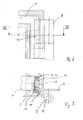
- FIG. 5 Of particular advantage is the embodiment of FIG. 5, wherein the leaf spring 23 is added in sections in the bore 20 and at least partially an approximately circular and adapted to the bore 20 circumference 24 has.
- the leaf spring 23 is already at least in the longitudinal direction of the web 13 fixed and does not wear on the mounting tabs 11. Otherwise it would be namely necessary, between the fastening tab 12 and the leg 11th to provide a corresponding space. So can the manufacture of the 19 interruption used hole 20 at the same time to accommodate the Leaf spring 23 create necessary space.
- tuned perimeter 24 also allow a certain amount of commitment the leaf spring 23 transversely to the web 13 - in the direction 25 (Fig. 5), since due to the Making the interruption 19, the edge 26 in this direction a small Undercut forms.
- the undercut through the edge 26 may, for example, during assembly of the Leaf spring 23 are used on the pivot bearing 5 to a short-term Fixation bring about.
- it is more advantageous for alignment if the Leaf spring 23 has an angled web 27, which on the lateral edge 28th of the fastening tab 11 is present. As a result, the leaf spring 23 receives an opposite the direction 25 acting defined orientation relative to the fastening tabs 11th and at the same time within the bore 20 at right angles to Attachment tabs 11 aligned.
- the function of the leaf spring 23 is easily seen: During assembly of the wing part 7th on the leg 12, the portion 18 within the interruption 19 and the Bore 20 arranged, as already described above. Section 18 works doing so on the spring tongue 29, which thereby in the direction 21 in the flat bore 20th is pivoted into it. During subsequent displacement of the wing part 7 is the Section 18 relative to the wing part 7 so far displaced that this between the edge 30 of the spring tongue 29 and the web 13.1 and 13.2 is located. Jumps the spring tongue 29 Now back, so it lies between the spring tongue 29 and the web 13.1 and 13.2, so that a pushing back only with simultaneous deformation of the leaf spring 23rd is possible.
- This can be done, for example, by means of a wing 34 (FIG. 5), which is laterally next to the engaging in the bore 20 circular arc-shaped section lies.
- the Wing 34 terminates at an edge parallel to the pivot bearing axis edge, which comes to rest near the paragraph 33.
- the heel 33 may be partially sectioned e.g. be deformed by means of a forming die, so that the deformed material section 35 - as indicated in Figure 7 - the leaf spring 23 partially overlapped.
- the paragraph 33 clearly next to the widened head of the ridge 13 is located so that the paragraph 33 with the molding stamp light is reachable.
- a production of the wing part 7 is made a drawn profile easily possible, as for the production of the function exclusively a post-processing is necessary.
Landscapes
- Engineering & Computer Science (AREA)
- Mechanical Engineering (AREA)
- Hinges (AREA)
- Closing And Opening Devices For Wings, And Checks For Wings (AREA)
- Dental Tools And Instruments Or Auxiliary Dental Instruments (AREA)
Abstract
Description
- Fig. 1
- ein Drehkippfenster mit einem gekippten Flügel,
- Fig. 2
- in einem größeren Maßstab den Lagerbock der Ausstellvorrichtung mit dem daran befestigten Ausstellarm,
- Fig. 3
- einen Schnitt entlang der Linie III-III in Fig. 2,
- Fig. 4
- einen Schnitt entlang der Linie IV-IV in Fig. 5 mit dem eingerasteten Sicherungselement,
- Fig. 5
- das Flügelteil mit dem Befestigungsteil in einer Draufsicht,
- Fig. 6
- den Schenkel des Ausstellarms und
- Fig. 7
- in einer vergrößerten Darstellung die Verbindung des Sicherungselementes mit dem Befestigungslappen.
- 1
- Flügel
- 2
- Rahmen
- 3
- Ausstellvorrichtung
- 4
- Ausstellarm
- 5
- Schwenklager
- 6
- Lagerbock
- 7
- Flügelteil
- 8
- Hülse
- 9
- Gelenkbolzen
- 10
- Bandlappen
- 11
- Befestigungslappen
- 12
- Schenkel
- 13
- Steg
- 13.1
- Steg
- 13.2
- Steg
- 14
- Ausnehmung
- 15
- Ausnehmung
- 16
- Schlitz
- 17
- Erweiterung
- 18
- Abschnitt
- 19
- Unterbrechung
- 20
- Bohrung
- 21
- Richtung
- 22
- Sicherungselement
- 23
- Blattfeder
- 24
- Umfang
- 25
- Richtung
- 26
- Kante
- 27
- Steg
- 28
- Rand
- 29
- Federzunge
- 30
- Rand
- 32
- Mittelachse
- 33
- Absatz
- 34
- Flügel
- 35
- Materialabschnitt
Claims (7)
- Ausstellvorrichtung für Fenster, Türen, insbesondere mit Drehkippflügel, mit mindestens einem Ausstellarm (4), der einerends am Flügel (1) schwenkbar und längsverschiebbar zu lagern und anderenends lösbar mit einem Schwenklager (5) kuppelbar ist, das aus einem am Blendrahmen (2) zu befestigenden Lagerbock (6) und einem Flügelteil (7) besteht, das mit dem Lagerbock (6) mittels eines eine Hülse (8) des Flügelteils (7) durchsetzenden Gelenkbolzens (9) schwenkbar verbunden ist wobei sich an die Hülse (8) ein abgewinkelter Bandlappen (10) anschließt, dessen Befestigungslappen (11) zur Kopplung mit einem abgewinkelten Schenkel (12) des Ausstellarms (4) oder mit einem Schenkels eines an dem Ausstellarm (4) angeschlossenen Winkelstücks vorgesehen ist, und wobei der Schenkel (12) mittels eines Sicherungselements (22) am Befestigungslappen (11) gehalten ist, dadurch gekennzeichnet, dass das Sicherungselement (22) aus einer Blattfeder (23) besteht, die mittig zwischen zwei Formschlusselementen (13.1, 13.2) liegt, dass die Formschlusselemente (13.1, 13.2) von einem unterbrochenen und im Querschnitt T-förmigen Steg (13) des Befestigungslappens (11) gebildet werden, und dass die Formschlusselemente (13.1, 13.2) in Öffnungen bzw. Ausnehmungen (14, 15) des Schenkels (12) einführbar sind und diese hintergreifen.
- Ausstellvorrichtung nach Anspruch 1, dadurch gekennzeichnet, dass der Steg (13) mittels einer Bohrung (20) durchbrochen wird.
- Ausstellvorrichtung nach Anspruch 2, dadurch gekennzeichnet, dass die Bohrung (20) als zylindrische Ausnehmung an dem Befestigungslappen (11) ausgeführt ist.
- Ausstellvorrichtung nach Anspruch 2 oder 3, dadurch gekennzeichnet, dass die Blattfeder (23) abschnittsweise in der Bohrung (20) aufgenommen ist und zumindest bereichsweise einen annähernd kreisförmigen und an die Bohrung (20) angepassten Umfang (24) hat.
- Ausstellvorrichtung nach einem der Ansprüche 1 bis 4, dadurch gekennzeichnet, dass die Blattfeder (23) einen abgewinkelten Steg (27) aufweist, der an dem Befestigungslappen (11) seitlich anliegt.
- Ausstellvorrichtung nach einem der Ansprüche 1 bis 5, dadurch gekennzeichnet, dass der Befestigungslappen (11) einen parallel zur Schwenklagerachse verlaufenden Absatz (33) aufweist, an dem die Blattfeder (23) zumindest bereichsweise anliegt.
- Ausstellvorrichtung nach einem der Ansprüche 1 bis 6, dadurch gekennzeichnet, dass der Befestigungslappen (11) eine randoffene und eine geschlossene Ausnehmung (14, 15) enthält, wobei die randoffene Ausnehmung (14) als Schlitz ausgebildet ist und die geschlossene Ausnehmung (15) einen Schlitz (16) mit einer Erweiterung (17) zum Durchtritt eines der T-förmigen Stege (13.1, 13.2) enthält.
Applications Claiming Priority (2)
| Application Number | Priority Date | Filing Date | Title |
|---|---|---|---|
| DE202004004927U | 2004-03-26 | ||
| DE202004004927U DE202004004927U1 (de) | 2004-03-26 | 2004-03-26 | Ausstellvorrichtung |
Publications (3)
| Publication Number | Publication Date |
|---|---|
| EP1580379A2 true EP1580379A2 (de) | 2005-09-28 |
| EP1580379A3 EP1580379A3 (de) | 2009-07-15 |
| EP1580379B1 EP1580379B1 (de) | 2010-06-02 |
Family
ID=34854235
Family Applications (1)
| Application Number | Title | Priority Date | Filing Date |
|---|---|---|---|
| EP05100856A Expired - Lifetime EP1580379B1 (de) | 2004-03-26 | 2005-02-08 | Ausstellvorrichtung für die Flügel von Fenstern, Türen od. dgl |
Country Status (4)
| Country | Link |
|---|---|
| EP (1) | EP1580379B1 (de) |
| AT (1) | ATE470039T1 (de) |
| DE (2) | DE202004004927U1 (de) |
| ES (1) | ES2343416T3 (de) |
Family Cites Families (3)
| Publication number | Priority date | Publication date | Assignee | Title |
|---|---|---|---|---|
| DE1923282U (de) * | 1965-06-30 | 1965-09-09 | Hans Bilstein | Ausstellstange fuer dreh-kipp-fenster od. dgl. |
| DE4040233C2 (de) * | 1990-12-15 | 1994-11-03 | Bilstein August Gmbh Co Kg | Schwenklager an einer Ausstellvorrichtung von Dreh-Kipp-Flügeln von Fenstern, Türen oder dergleichen |
| DE9401699U1 (de) * | 1994-02-02 | 1994-03-17 | Roto Frank Ag, 70771 Leinfelden-Echterdingen | Ausstellvorrichtung für Fenster, Türen o.dgl. |
-
2004
- 2004-03-26 DE DE202004004927U patent/DE202004004927U1/de not_active Expired - Lifetime
-
2005
- 2005-02-08 DE DE502005009662T patent/DE502005009662D1/de not_active Expired - Lifetime
- 2005-02-08 ES ES05100856T patent/ES2343416T3/es not_active Expired - Lifetime
- 2005-02-08 EP EP05100856A patent/EP1580379B1/de not_active Expired - Lifetime
- 2005-02-08 AT AT05100856T patent/ATE470039T1/de active
Also Published As
| Publication number | Publication date |
|---|---|
| DE502005009662D1 (de) | 2010-07-15 |
| EP1580379A3 (de) | 2009-07-15 |
| ATE470039T1 (de) | 2010-06-15 |
| EP1580379B1 (de) | 2010-06-02 |
| DE202004004927U1 (de) | 2005-08-11 |
| ES2343416T3 (es) | 2010-07-30 |
Similar Documents
| Publication | Publication Date | Title |
|---|---|---|
| EP4180601B1 (de) | Türband mit länglichem führungsschlitten | |
| EP1072745A1 (de) | Beschlag für die Verriegelung von Fenstern oder Türen | |
| WO1990015911A1 (de) | Scharnier | |
| EP1308590A1 (de) | Kantriegel für eine Tür | |
| DE8526659U1 (de) | Flügellager für ein Fenster, eine Tür od. dgl. | |
| EP0249682A2 (de) | Ausstellvorrichtung für die Flügel von Fenster, Türen od.dgl. mit Zuschlagsicherung für den geöffneten Flügel | |
| DE10050796C1 (de) | Scharnier | |
| EP1580379B1 (de) | Ausstellvorrichtung für die Flügel von Fenstern, Türen od. dgl | |
| DE19758907B4 (de) | Einen Überschlag aufweisender Flügel eines Fensters, einer Tür oder dergleichen, mit einem Scharnierbeschlag sowie Montageverfahren des Scharnierbeschlags | |
| EP0246431A2 (de) | Ausstellvorrichtung für Kippflügel, insbesondere Drehkipp- oder auch Schiebekippflügel, von Fenstern, Türen od. dgl. | |
| EP1759081B1 (de) | Ausstellvorrichtung | |
| EP3034727B1 (de) | Sperrbuegelschloss, mit einem sperrbuegel | |
| DE20012351U1 (de) | Fenster oder Tür mit Entlastungseinrichtung | |
| EP2811093B1 (de) | An einem Blendrahmen einer Tür oder eines Fensters festlegbares Trägerteil eines Schwenkbeschlages | |
| DE9301655U1 (de) | Scharnierbeschlag | |
| DE60115160T2 (de) | Zwischenbeschlag für Tür oder Fenster für nicht sichtbaren Scharnierbeschlag | |
| EP2374973B1 (de) | Band für Türen, Fenster oder dergleichen | |
| DE7112124U (de) | Ausstellvorrichtung fur Kipp Schwenkflügel von Fenstern, Türen od | |
| WO2007087945A1 (de) | Bandanordnung zur scharniergelenkigen verbindung eines flügels einer tür, eines fensters oder dergleichen, an einem rahmen | |
| DE602004006501T2 (de) | Teleskop-Fensterstrebe | |
| AT379648B (de) | Tuerbeschlag | |
| EP3205803B1 (de) | Vorrichtung zur dämpfung und begrenzung einer öffnungsbewegung | |
| CH562386A5 (de) | ||
| DE2551316A1 (de) | Ausstellvorrichtung, insbesondere fuer wahlweisen links- oder rechtsanschlag fuer fluegel von tueren, fenstern o.dgl. | |
| DE10306378A1 (de) | Beschlagteil |
Legal Events
| Date | Code | Title | Description |
|---|---|---|---|
| PUAI | Public reference made under article 153(3) epc to a published international application that has entered the european phase |
Free format text: ORIGINAL CODE: 0009012 |
|
| AK | Designated contracting states |
Kind code of ref document: A2 Designated state(s): AT BE BG CH CY CZ DE DK EE ES FI FR GB GR HU IE IS IT LI LT LU MC NL PL PT RO SE SI SK TR |
|
| AX | Request for extension of the european patent |
Extension state: AL BA HR LV MK YU |
|
| PUAL | Search report despatched |
Free format text: ORIGINAL CODE: 0009013 |
|
| AK | Designated contracting states |
Kind code of ref document: A3 Designated state(s): AT BE BG CH CY CZ DE DK EE ES FI FR GB GR HU IE IS IT LI LT LU MC NL PL PT RO SE SI SK TR |
|
| AX | Request for extension of the european patent |
Extension state: AL BA HR LV MK YU |
|
| 17P | Request for examination filed |
Effective date: 20090819 |
|
| GRAP | Despatch of communication of intention to grant a patent |
Free format text: ORIGINAL CODE: EPIDOSNIGR1 |
|
| AKX | Designation fees paid |
Designated state(s): AT BE BG CH CY CZ DE DK EE ES FI FR GB GR HU IE IS IT LI LT LU MC NL PL PT RO SE SI SK TR |
|
| GRAF | Information related to payment of grant fee modified |
Free format text: ORIGINAL CODE: EPIDOSCIGR3 |
|
| GRAS | Grant fee paid |
Free format text: ORIGINAL CODE: EPIDOSNIGR3 |
|
| GRAA | (expected) grant |
Free format text: ORIGINAL CODE: 0009210 |
|
| AK | Designated contracting states |
Kind code of ref document: B1 Designated state(s): AT BE BG CH CY CZ DE DK EE ES FI FR GB GR HU IE IS IT LI LT LU MC NL PL PT RO SE SI SK TR |
|
| REG | Reference to a national code |
Ref country code: GB Ref legal event code: FG4D Free format text: NOT ENGLISH |
|
| REG | Reference to a national code |
Ref country code: CH Ref legal event code: EP |
|
| REG | Reference to a national code |
Ref country code: IE Ref legal event code: FG4D Free format text: LANGUAGE OF EP DOCUMENT: GERMAN |
|
| REF | Corresponds to: |
Ref document number: 502005009662 Country of ref document: DE Date of ref document: 20100715 Kind code of ref document: P |
|
| REG | Reference to a national code |
Ref country code: ES Ref legal event code: FG2A Ref document number: 2343416 Country of ref document: ES Kind code of ref document: T3 |
|
| REG | Reference to a national code |
Ref country code: NL Ref legal event code: VDEP Effective date: 20100602 |
|
| PG25 | Lapsed in a contracting state [announced via postgrant information from national office to epo] |
Ref country code: LT Free format text: LAPSE BECAUSE OF FAILURE TO SUBMIT A TRANSLATION OF THE DESCRIPTION OR TO PAY THE FEE WITHIN THE PRESCRIBED TIME-LIMIT Effective date: 20100602 Ref country code: SE Free format text: LAPSE BECAUSE OF FAILURE TO SUBMIT A TRANSLATION OF THE DESCRIPTION OR TO PAY THE FEE WITHIN THE PRESCRIBED TIME-LIMIT Effective date: 20100602 |
|
| LTIE | Lt: invalidation of european patent or patent extension |
Effective date: 20100602 |
|
| PG25 | Lapsed in a contracting state [announced via postgrant information from national office to epo] |
Ref country code: FI Free format text: LAPSE BECAUSE OF FAILURE TO SUBMIT A TRANSLATION OF THE DESCRIPTION OR TO PAY THE FEE WITHIN THE PRESCRIBED TIME-LIMIT Effective date: 20100602 Ref country code: SI Free format text: LAPSE BECAUSE OF FAILURE TO SUBMIT A TRANSLATION OF THE DESCRIPTION OR TO PAY THE FEE WITHIN THE PRESCRIBED TIME-LIMIT Effective date: 20100602 |
|
| PG25 | Lapsed in a contracting state [announced via postgrant information from national office to epo] |
Ref country code: CY Free format text: LAPSE BECAUSE OF FAILURE TO SUBMIT A TRANSLATION OF THE DESCRIPTION OR TO PAY THE FEE WITHIN THE PRESCRIBED TIME-LIMIT Effective date: 20100602 Ref country code: PL Free format text: LAPSE BECAUSE OF FAILURE TO SUBMIT A TRANSLATION OF THE DESCRIPTION OR TO PAY THE FEE WITHIN THE PRESCRIBED TIME-LIMIT Effective date: 20100602 |
|
| REG | Reference to a national code |
Ref country code: IE Ref legal event code: FD4D |
|
| PG25 | Lapsed in a contracting state [announced via postgrant information from national office to epo] |
Ref country code: IE Free format text: LAPSE BECAUSE OF FAILURE TO SUBMIT A TRANSLATION OF THE DESCRIPTION OR TO PAY THE FEE WITHIN THE PRESCRIBED TIME-LIMIT Effective date: 20100602 Ref country code: NL Free format text: LAPSE BECAUSE OF FAILURE TO SUBMIT A TRANSLATION OF THE DESCRIPTION OR TO PAY THE FEE WITHIN THE PRESCRIBED TIME-LIMIT Effective date: 20100602 Ref country code: EE Free format text: LAPSE BECAUSE OF FAILURE TO SUBMIT A TRANSLATION OF THE DESCRIPTION OR TO PAY THE FEE WITHIN THE PRESCRIBED TIME-LIMIT Effective date: 20100602 |
|
| PG25 | Lapsed in a contracting state [announced via postgrant information from national office to epo] |
Ref country code: IS Free format text: LAPSE BECAUSE OF FAILURE TO SUBMIT A TRANSLATION OF THE DESCRIPTION OR TO PAY THE FEE WITHIN THE PRESCRIBED TIME-LIMIT Effective date: 20101002 Ref country code: SK Free format text: LAPSE BECAUSE OF FAILURE TO SUBMIT A TRANSLATION OF THE DESCRIPTION OR TO PAY THE FEE WITHIN THE PRESCRIBED TIME-LIMIT Effective date: 20100602 Ref country code: RO Free format text: LAPSE BECAUSE OF FAILURE TO SUBMIT A TRANSLATION OF THE DESCRIPTION OR TO PAY THE FEE WITHIN THE PRESCRIBED TIME-LIMIT Effective date: 20100602 Ref country code: CZ Free format text: LAPSE BECAUSE OF FAILURE TO SUBMIT A TRANSLATION OF THE DESCRIPTION OR TO PAY THE FEE WITHIN THE PRESCRIBED TIME-LIMIT Effective date: 20100602 Ref country code: PT Free format text: LAPSE BECAUSE OF FAILURE TO SUBMIT A TRANSLATION OF THE DESCRIPTION OR TO PAY THE FEE WITHIN THE PRESCRIBED TIME-LIMIT Effective date: 20101004 |
|
| PLBE | No opposition filed within time limit |
Free format text: ORIGINAL CODE: 0009261 |
|
| STAA | Information on the status of an ep patent application or granted ep patent |
Free format text: STATUS: NO OPPOSITION FILED WITHIN TIME LIMIT |
|
| PG25 | Lapsed in a contracting state [announced via postgrant information from national office to epo] |
Ref country code: DK Free format text: LAPSE BECAUSE OF FAILURE TO SUBMIT A TRANSLATION OF THE DESCRIPTION OR TO PAY THE FEE WITHIN THE PRESCRIBED TIME-LIMIT Effective date: 20100602 |
|
| 26N | No opposition filed |
Effective date: 20110303 |
|
| REG | Reference to a national code |
Ref country code: DE Ref legal event code: R097 Ref document number: 502005009662 Country of ref document: DE Effective date: 20110302 |
|
| PG25 | Lapsed in a contracting state [announced via postgrant information from national office to epo] |
Ref country code: MC Free format text: LAPSE BECAUSE OF NON-PAYMENT OF DUE FEES Effective date: 20110228 |
|
| REG | Reference to a national code |
Ref country code: CH Ref legal event code: PL |
|
| GBPC | Gb: european patent ceased through non-payment of renewal fee |
Effective date: 20110208 |
|
| PG25 | Lapsed in a contracting state [announced via postgrant information from national office to epo] |
Ref country code: CH Free format text: LAPSE BECAUSE OF NON-PAYMENT OF DUE FEES Effective date: 20110228 Ref country code: LI Free format text: LAPSE BECAUSE OF NON-PAYMENT OF DUE FEES Effective date: 20110228 |
|
| PG25 | Lapsed in a contracting state [announced via postgrant information from national office to epo] |
Ref country code: GB Free format text: LAPSE BECAUSE OF NON-PAYMENT OF DUE FEES Effective date: 20110208 |
|
| REG | Reference to a national code |
Ref country code: AT Ref legal event code: MM01 Ref document number: 470039 Country of ref document: AT Kind code of ref document: T Effective date: 20110208 |
|
| PG25 | Lapsed in a contracting state [announced via postgrant information from national office to epo] |
Ref country code: AT Free format text: LAPSE BECAUSE OF NON-PAYMENT OF DUE FEES Effective date: 20110208 |
|
| PG25 | Lapsed in a contracting state [announced via postgrant information from national office to epo] |
Ref country code: LU Free format text: LAPSE BECAUSE OF NON-PAYMENT OF DUE FEES Effective date: 20110208 |
|
| PG25 | Lapsed in a contracting state [announced via postgrant information from national office to epo] |
Ref country code: BG Free format text: LAPSE BECAUSE OF FAILURE TO SUBMIT A TRANSLATION OF THE DESCRIPTION OR TO PAY THE FEE WITHIN THE PRESCRIBED TIME-LIMIT Effective date: 20100902 Ref country code: TR Free format text: LAPSE BECAUSE OF FAILURE TO SUBMIT A TRANSLATION OF THE DESCRIPTION OR TO PAY THE FEE WITHIN THE PRESCRIBED TIME-LIMIT Effective date: 20100602 |
|
| PG25 | Lapsed in a contracting state [announced via postgrant information from national office to epo] |
Ref country code: HU Free format text: LAPSE BECAUSE OF FAILURE TO SUBMIT A TRANSLATION OF THE DESCRIPTION OR TO PAY THE FEE WITHIN THE PRESCRIBED TIME-LIMIT Effective date: 20100602 |
|
| PG25 | Lapsed in a contracting state [announced via postgrant information from national office to epo] |
Ref country code: GR Free format text: LAPSE BECAUSE OF FAILURE TO SUBMIT A TRANSLATION OF THE DESCRIPTION OR TO PAY THE FEE WITHIN THE PRESCRIBED TIME-LIMIT Effective date: 20100602 |
|
| REG | Reference to a national code |
Ref country code: FR Ref legal event code: PLFP Year of fee payment: 12 |
|
| REG | Reference to a national code |
Ref country code: FR Ref legal event code: PLFP Year of fee payment: 13 |
|
| REG | Reference to a national code |
Ref country code: FR Ref legal event code: PLFP Year of fee payment: 14 |
|
| PGFP | Annual fee paid to national office [announced via postgrant information from national office to epo] |
Ref country code: DE Payment date: 20220221 Year of fee payment: 18 |
|
| PGFP | Annual fee paid to national office [announced via postgrant information from national office to epo] |
Ref country code: IT Payment date: 20220228 Year of fee payment: 18 Ref country code: FR Payment date: 20220219 Year of fee payment: 18 Ref country code: ES Payment date: 20220301 Year of fee payment: 18 Ref country code: BE Payment date: 20220218 Year of fee payment: 18 |
|
| REG | Reference to a national code |
Ref country code: DE Ref legal event code: R119 Ref document number: 502005009662 Country of ref document: DE |
|
| REG | Reference to a national code |
Ref country code: BE Ref legal event code: MM Effective date: 20230228 |
|
| PG25 | Lapsed in a contracting state [announced via postgrant information from national office to epo] |
Ref country code: IT Free format text: LAPSE BECAUSE OF NON-PAYMENT OF DUE FEES Effective date: 20230208 Ref country code: FR Free format text: LAPSE BECAUSE OF NON-PAYMENT OF DUE FEES Effective date: 20230228 Ref country code: DE Free format text: LAPSE BECAUSE OF NON-PAYMENT OF DUE FEES Effective date: 20230901 |
|
| PG25 | Lapsed in a contracting state [announced via postgrant information from national office to epo] |
Ref country code: BE Free format text: LAPSE BECAUSE OF NON-PAYMENT OF DUE FEES Effective date: 20230228 |
|
| REG | Reference to a national code |
Ref country code: ES Ref legal event code: FD2A Effective date: 20240402 |
|
| PG25 | Lapsed in a contracting state [announced via postgrant information from national office to epo] |
Ref country code: ES Free format text: LAPSE BECAUSE OF NON-PAYMENT OF DUE FEES Effective date: 20230209 |
|
| PG25 | Lapsed in a contracting state [announced via postgrant information from national office to epo] |
Ref country code: ES Free format text: LAPSE BECAUSE OF NON-PAYMENT OF DUE FEES Effective date: 20230209 |